EP2988693B1 - Non-invasive device for treatment of the skin using laser light - Google Patents
Non-invasive device for treatment of the skin using laser light Download PDFInfo
- Publication number
- EP2988693B1 EP2988693B1 EP14719317.1A EP14719317A EP2988693B1 EP 2988693 B1 EP2988693 B1 EP 2988693B1 EP 14719317 A EP14719317 A EP 14719317A EP 2988693 B1 EP2988693 B1 EP 2988693B1
- Authority
- EP
- European Patent Office
- Prior art keywords
- laser pulse
- pulse
- laser
- plasma
- invasive device
- Prior art date
- Legal status (The legal status is an assumption and is not a legal conclusion. Google has not performed a legal analysis and makes no representation as to the accuracy of the status listed.)
- Active
Links
Images

Classifications
-
- A—HUMAN NECESSITIES
- A61—MEDICAL OR VETERINARY SCIENCE; HYGIENE
- A61B—DIAGNOSIS; SURGERY; IDENTIFICATION
- A61B18/00—Surgical instruments, devices or methods for transferring non-mechanical forms of energy to or from the body
- A61B18/18—Surgical instruments, devices or methods for transferring non-mechanical forms of energy to or from the body by applying electromagnetic radiation, e.g. microwaves
- A61B18/20—Surgical instruments, devices or methods for transferring non-mechanical forms of energy to or from the body by applying electromagnetic radiation, e.g. microwaves using laser
- A61B18/203—Surgical instruments, devices or methods for transferring non-mechanical forms of energy to or from the body by applying electromagnetic radiation, e.g. microwaves using laser applying laser energy to the outside of the body
-
- A—HUMAN NECESSITIES
- A61—MEDICAL OR VETERINARY SCIENCE; HYGIENE
- A61B—DIAGNOSIS; SURGERY; IDENTIFICATION
- A61B18/00—Surgical instruments, devices or methods for transferring non-mechanical forms of energy to or from the body
- A61B18/18—Surgical instruments, devices or methods for transferring non-mechanical forms of energy to or from the body by applying electromagnetic radiation, e.g. microwaves
- A61B18/20—Surgical instruments, devices or methods for transferring non-mechanical forms of energy to or from the body by applying electromagnetic radiation, e.g. microwaves using laser
-
- A—HUMAN NECESSITIES
- A61—MEDICAL OR VETERINARY SCIENCE; HYGIENE
- A61B—DIAGNOSIS; SURGERY; IDENTIFICATION
- A61B17/00—Surgical instruments, devices or methods, e.g. tourniquets
- A61B2017/00017—Electrical control of surgical instruments
- A61B2017/00137—Details of operation mode
- A61B2017/00154—Details of operation mode pulsed
- A61B2017/00172—Pulse trains, bursts, intermittent continuous operation
- A61B2017/00176—Two pulses, e.g. second pulse having an effect different from the first one
-
- A—HUMAN NECESSITIES
- A61—MEDICAL OR VETERINARY SCIENCE; HYGIENE
- A61B—DIAGNOSIS; SURGERY; IDENTIFICATION
- A61B18/00—Surgical instruments, devices or methods for transferring non-mechanical forms of energy to or from the body
- A61B2018/00315—Surgical instruments, devices or methods for transferring non-mechanical forms of energy to or from the body for treatment of particular body parts
- A61B2018/00452—Skin
- A61B2018/00458—Deeper parts of the skin, e.g. treatment of vascular disorders or port wine stains
-
- A—HUMAN NECESSITIES
- A61—MEDICAL OR VETERINARY SCIENCE; HYGIENE
- A61B—DIAGNOSIS; SURGERY; IDENTIFICATION
- A61B18/00—Surgical instruments, devices or methods for transferring non-mechanical forms of energy to or from the body
- A61B2018/00315—Surgical instruments, devices or methods for transferring non-mechanical forms of energy to or from the body for treatment of particular body parts
- A61B2018/00452—Skin
- A61B2018/0047—Upper parts of the skin, e.g. skin peeling or treatment of wrinkles
-
- A—HUMAN NECESSITIES
- A61—MEDICAL OR VETERINARY SCIENCE; HYGIENE
- A61B—DIAGNOSIS; SURGERY; IDENTIFICATION
- A61B18/00—Surgical instruments, devices or methods for transferring non-mechanical forms of energy to or from the body
- A61B2018/00636—Sensing and controlling the application of energy
- A61B2018/00642—Sensing and controlling the application of energy with feedback, i.e. closed loop control
-
- A—HUMAN NECESSITIES
- A61—MEDICAL OR VETERINARY SCIENCE; HYGIENE
- A61B—DIAGNOSIS; SURGERY; IDENTIFICATION
- A61B18/00—Surgical instruments, devices or methods for transferring non-mechanical forms of energy to or from the body
- A61B2018/00636—Sensing and controlling the application of energy
- A61B2018/00696—Controlled or regulated parameters
- A61B2018/00702—Power or energy
-
- A—HUMAN NECESSITIES
- A61—MEDICAL OR VETERINARY SCIENCE; HYGIENE
- A61B—DIAGNOSIS; SURGERY; IDENTIFICATION
- A61B18/00—Surgical instruments, devices or methods for transferring non-mechanical forms of energy to or from the body
- A61B2018/00636—Sensing and controlling the application of energy
- A61B2018/00696—Controlled or regulated parameters
- A61B2018/00761—Duration
-
- A—HUMAN NECESSITIES
- A61—MEDICAL OR VETERINARY SCIENCE; HYGIENE
- A61B—DIAGNOSIS; SURGERY; IDENTIFICATION
- A61B18/00—Surgical instruments, devices or methods for transferring non-mechanical forms of energy to or from the body
- A61B2018/00636—Sensing and controlling the application of energy
- A61B2018/00773—Sensed parameters
- A61B2018/0088—Vibration
Definitions
- This invention relates to a non-invasive device for treatment of skin tissue using laser light.
- Such non-invasive skin treatment device is, e.g., known from the published international patent application WO 2008/001284 A2 .
- Said application discloses a skin treatment device with a laser source and focusing optics. The device creates a focal spot in a dermis layer of the skin to be treated.
- the power of the laser is selected such that laser-induced optical breakdown (LIOB) affects the skin in order to stimulate re-growth of skin tissue and reduce wrinkles.
- LIOB laser-induced optical breakdown
- the device is able to provide a laser-induced optical breakdown (LIOB) phenomenon in the skin by providing sufficiently intense laser pulses.
- LIOB laser-induced optical breakdown
- This LIOB is based on strong non-linear absorption of the laser light by the skin tissue, which occurs above a certain threshold value for the power density of the laser light.
- This strong absorption causes a very localized plasma that is able to damage or even remove tissue at the location of said plasma. The effect is local, because below the threshold there is zero or very little linear and non-linear absorption, while above the threshold a plasma is generated.
- LIOB occurs inside the skin tissue when the light intensity is sufficiently high to produce a critical free-electron density, which is about 10 21 cm -3 . To generate such high intensity locally inside the skin, the requirements on the light source to create LIOB are relatively high.
- WO 2012/107830 discloses a system for treating a region of the epidermis, comprising at least one laser energy source, a time control device to generate a laser beam, and a laser energy focusing system arranged and produced to direct a laser beam on said region of the epidermis.
- the control device generates a laser beam comprising a plurality of composite pulses, emitted at a base frequency, each composite pulse comprising a sequence of sub-pulses at a higher frequency than said base frequency.
- each composite pulse comprises a pre-pulse of greater duration and a train of sub-pulses of lesser duration.
- the pre-pulse has an energy per unit of surface area such as to generate plasma to remove the epidermis but such as not to interact with the middle layers of the dermis.
- the sub-pulses have an energy per unit of surface area adapted to generate a cold ablation, i.e. without plasma or substantially without plasma.
- a first aspect of the invention provides a non-invasive device for treatment of skin using laser light.
- the non-invasive device for treatment of skin comprises a light emission system for generating a first laser pulse and a subsequent second laser pulse at a predefined time delay after the first laser pulse.
- the non-invasive device further comprises an optical system for focusing, in use, the first laser pulse and the second laser pulse into a focal spot at a treatment location inside the skin tissue.
- the first laser pulse has a first power density (W/cm 2 ) in the focal spot, a first pulse duration and a first pulse energy (mJ) for initiating a plasma in the skin tissue at the treatment location.
- the subsequent second laser pulse has a second power density in the focal spot being lower than the first power density, a second pulse duration and a second pulse energy.
- the first pulse duration is in a range between 1 and 1,000 picoseconds
- the second pulse duration is at least 10 times longer than the first pulse duration and is in a range between 1 and 1,000 nanoseconds
- the time delay is in a range between 1 nanosecond and 10 microseconds
- the first pulse energy is in a range between 0.1 and 2 mJ
- the second pulse energy is 10 to 100 times higher than the first pulse energy and is in a range between 1 and 200 mJ for sustaining or intensifying, by generating the second laser pulse at said predefined time delay after the first laser pulse, the plasma initiated by the first laser pulse by absorption of at least part of the energy of the second laser pulse by the plasma initiated by the first laser pulse to generate breakdown of the skin tissue in the treatment location. It is in this manner that, in use, the first laser pulse and the second laser pulse together generate Laser-Induced Optical Breakdown at the treatment location.
- the use of two laser pulses to generate Laser-Induced Optical Breakdown relaxes the boundary conditions of the light emission system significantly.
- the first laser pulse creates a plasma at the treatment location inside the skin tissue, and the second laser pulse sustains or even enhances (or feeds) this plasma created by the first laser pulse.
- This combination of the first laser pulse and the second laser pulse creates a sufficiently high electron density at the treatment location to generate LIOB.
- LIOB is usually produced using a single laser pulse.
- a laser source capable to produce this single laser pulse in the known LIOB system must be able to produce a relatively short laser pulse (pulse duration less than 1,000 picoseconds) having a relatively high energy (up to 10 mJ).
- This combination of requirements to generate the single laser pulse in the known non-invasive LIOB system causes the known laser source to be relatively bulky, such as an industrially used Nd:YAG laser source.
- Using such a laser source in the known non-invasive LIOB systems makes the known LIOB systems relatively expensive and causes the operation of such LIOB system to require specialists that know how to operate such a high-power laser source.
- the inventors have found that, by splitting up the LIOB generation between the first laser pulse and the second laser pulse, the boundary conditions of each of the first laser pulse and the second laser pulse may be relaxed significantly such that also the requirements on the light emission system may be relaxed significantly, thereby reducing the overall cost of the non-invasive skin treatment device significantly.
- the light emission system may comprise two different laser sources which produce, respectively, the first laser pulse and the subsequent second laser pulse.
- the first pulse duration (or first pulse width) of the first laser pulse may, for example, be 10 times shorter than the second pulse duration (or second pulse width), or even up to 500 to 1,000 times shorter than the second pulse duration (or second pulse width) of the second laser pulse.
- the first pulse duration or first pulse width and the second pulse duration or second pulse width are typically measured at the Full-Width-Half-Maximum (further also indicted as FWHM) of the first laser pulse and second laser pulse, respectively.
- the first power density of the first pulse is higher than the second power density of the second pulse, while the overall energy of the second laser pulse is 10 to 100 times higher than the energy of the first laser pulse. Because the requirements for the first laser pulse and the second laser pulse are so different, the two different laser sources may be specifically tuned to produce these first laser pulses and second laser pulses, which results in a more cost-effective solution. But, in addition to a reduction in costs, the non-invasive device may also become less bulky, which may also be an important aspect for the consumer market.
- the device may be able to be operated by non-specialists, because the individual laser power to produce the first laser pulse and the second laser pulse is significantly less than the laser power required for the single laser pulse LIOB generation, which is approximately a factor of 20 higher than the highest power of the first laser pulse or the second laser pulse.
- This reduction in individual laser power to produce the first laser pulse and the second laser pulse in the non-invasive device according to the invention has the further benefit that it reduces any possible damage to the skin tissue, which would be due to the treatment of the skin using such high power laser light, and that it reduces any possible damage of optical elements guiding the first laser pulse and the second laser pulse to the skin tissue.
- the second laser pulse is emitted at the predefined time delay after the first laser pulse, wherein the time delay is in a range between 1 nanosecond and10 microseconds.
- a benefit of delaying the second laser pulse after the first laser pulse is that the absorption efficiency of the second laser pulse by the plasma generated by the first laser pulse is improved. Because some time is required for the first laser pulse to generate the plasma at the treatment location, the delay of the second laser pulse will ensure that the second laser pulse arrives at the treatment location when the plasma is 'ready' to absorb the radiation of the second laser pulse. The exact time delay required to achieve the highest efficiency may be experimentally determined and may differ depending on the depth inside the skin where the treatment location is located.
- the time delay is typically measured from a maximum intensity of the first laser pulse to a maximum intensity of the second laser pulse. Therefore, the first laser pulse and the second laser pulse may partially overlap. As indicated before, the effect of the time delay is that the efficiency of the absorption of the light of the second light pulse by the plasma is enhanced due to the fact that some time is required for the first light pulse to generate the plasma inside the skin tissue. Again, the exact value of the time delay required to achieve the highest efficiency may be experimentally determined and may differ depending on the depth inside the skin where the treatment location is located.
- a wavelength of the second laser pulse is selected to generate off-resonance absorption of the energy of the second laser pulse by the plasma at the treatment location to sustain or intensify the plasma initiated by the first laser pulse.
- the non-invasive device according to the invention is configured for emitting a wavelength of the second laser pulse which is selected to be included in an absorption peak of Inverse Bremsstrahlung of the plasma created by the first laser pulse.
- the second laser pulse may even enhance (or feed) the plasma created by the first laser pulse - as already mentioned before.
- off-resonance absorption is different from the on-resonance absorption where the wavelength of the plasma feeding light is tuned to the peak resonance absorption of the excited target atoms used, for example, for ablation.
- On-resonance absorption requires critical pulse parameters matching the energy levels of the target atoms or molecules. The energy is transferred to the targeted atoms, not to the plasma itself.
- off-resonance absorption is used for which substantially the only restriction to the wavelength of the second laser pulse is that the laser pulse efficiently reaches the plasma inside the skin tissue, initiated by the first laser pulse.
- the first laser pulse comprises polarized light.
- polarized laser light may be used.
- the efficiency of the initiation of the plasma at the treatment location inside the skin tissue may be further improved - allowing the peak intensity or peak power density of the first laser pulse to be further reduced.
- the subsequent, second laser pulse is used for sustaining or feeding the initiated plasma and there is no real benefit when this second laser pulse is polarized.
- the wavelength of the first laser pulse is approximately 1064 nanometers.
- the wavelength of the second laser pulse may be any wavelength that reaches the plasma inside the skin.
- the light emission system comprises a first laser for emitting the first laser pulse and comprises a second laser for emitting the second laser pulse, the second laser being different from the first laser.
- the first laser pulse is different from the second laser pulse. Due to the use of the first laser pulse and the subsequent, second laser pulse, the individual requirements on each of the first laser pulse and the second laser pulse have already been reduced. As a result, the light emission system may already have relaxed boundary conditions in case the light is generated using a single laser. However, when using the first laser to generate the first laser pulse and the second laser to generate the second laser pulse, the first laser and the second laser may be specifically tuned to produce these first laser pulses and second laser pulses, respectively, which results in a more cost-effective solution.
- the treatment location is in a dermis layer of the skin, below the epidermis layer. Therefore, the wavelength used for the first laser pulse and the second laser pulse should reach this dermis layer inside the skin and should have sufficient intensity or power density at this dermis layer to ensure that the first laser pulse initiates the plasma and that the second laser pulse sustains or enhances (or feeds) the plasma sufficiently to generate enough critical free-electron density to achieve LIOB.
- the non-invasive device comprises a feedback system for determining a focusing depth of the first laser pulse and/or the second laser pulse at the treatment location.
- a feedback system may, for example, be configured for measuring a Second Harmonic Generated signal (further also indicated as SHG signal) reflected from the treatment location.
- SHG signal may be a measure of the collagen content present at the treatment location and so the SHG signal measured may be used to see whether the optical system focuses inside the dermis layer.
- Collagen strains present in the dermis layer have birefringent characteristics, such that when hit by light, they reflect part of the light as a SHG signal.
- the measuring of the SHG signal may be used to determine whether the optical system focuses at the correct depth inside the skin.
- the SHG signal may be created using a further light source in the non-invasive device according to the invention.
- the SHG signal may be created using, for example, part of the impinging second laser pulse.
- the focusing depth is determined using polarization-sensitive birefringent detection for detecting the collagen strains in the dermis layer.
- any other known feedback system for determining a focusing depth inside the skin may be used.
- the non-invasive device comprises a feedback system for detecting the plasma inside the skin tissue and/or for detecting an acoustic signal generated during the Laser-Induced Optical Breakdown at the treatment location.
- Detecting the plasma inside the skin tissue may, for example, be done by an optical detector, which detects light of a different wavelength than the wavelength of any of the first laser pulse and the second laser pulse, as the plasma will emit light in a very broad wavelength range. Detection of the presence of the plasma is an indicator of the efficiency of the LIOB.
- the feedback system may comprise an acoustic detector to detect the acoustic signal generated during LIOB. Due to the rapid initiation of the plasma and the creation of lesions, an acoustic wave will propagate through the skin tissue which may be detected using an acoustic detector and which may be used as a measure of the effectiveness of the LIOB process.
- the method of skin treatment using laser comprises the steps of:
- the first laser pulse has a first power density (W/cm 2 ) in the focal spot, a first pulse duration, and a first pulse energy for initiating a plasma in the skin tissue at the treatment location.
- the subsequent second laser pulse has a second power density in the focal spot being lower than the first power density, a second pulse duration and a second pulse energy.
- the first pulse duration is in a range between 1 and 1,000 picoseconds
- the second pulse duration is at least 10 times longer than the first pulse duration and is in a range between 1 and 1,000 nanoseconds
- the time delay is in a range between 1 nanosecond and 10 microseconds
- the first pulse energy is in a range between 0.1 and 2 mJ
- the second pulse energy is 10 to 100 times higher than the first pulse energy and is in a range between 1 and 200 mJ for sustaining or intensifying, by generating the second laser pulse at said predefined time delay after the first laser pulse, the plasma initiated by the first laser pulse by absorption of at least part of the energy of the second laser pulse by the plasma initiated by the first laser pulse to generate breakdown of the skin tissue in the treatment location.
- the first laser pulse and the second laser pulse together generate Laser-Induced Optical Breakdown at the treatment location.
- the second laser pulse may also enhance or feed the plasma generated by the first laser pulse.
- the first laser pulse is generated by a first laser and the second laser pulse is generated by a second laser different from the first laser.
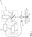
- FIG. 1 schematically shows a non-invasive device 100 according to the invention.
- the non-invasive device 100 comprises a light emission system 110 for generating a first laser pulse 130 and a subsequent second laser pulse 150.
- the non-invasive device 100 further comprises an optical system 160, for example, a microscope objective 10 or any other lens element 160 for focusing the first laser pulse 130 and the second laser pulse 150 into a focal spot at a treatment location 210 inside the skin tissue 200.
- the first laser pulse 130 has a relatively high first power density (W/cm 2 ) in the focal spot, a relatively short first pulse duration (illustrated by means of the pulse shape indicated by reference number 130) and a first pulse energy.
- the first laser pulse 130 is configured such that a plasma is initiated in the skin tissue 200 in the focal spot at the treatment location 210.
- the second laser pulse 150 has a relatively low power density (W/cm 2 ) in the focal spot, a relatively long second pulse duration (illustrated by means of the pulse shape indicated by reference number 150), and a relatively high pulse energy.
- the second laser pulse 150 is configured for sustaining or feeding (or enhancing) the plasma initiated at the same treatment location by the first laser pulse 130 to create a sufficiently high free-electron density at the treatment location 210 to generate Laser-Induced Optical Breakdown (further also indicated as LIOB).
- the second laser pulse 150 is generated at a sufficiently short predefined time delay after the first laser pulse, such that after said time delay the plasma initiated by the first laser pulse 130 is still present and able to absorp the energy of the second laser pulse 150.
- the use of the first laser pulse 130 together with the subsequent second laser pulse 150 to generate LIOB relaxes the boundary conditions of the light emission system 110 significantly.
- LIOB is usually produced using a single laser pulse. This single laser pulse in the known LIOB system has a relatively short laser pulse duration (pulse duration less than 1,000 picoseconds) while having a relatively high energy (up to 10 milli-Joules).
- This combination of requirements to generate the single laser pulse in the known non-invasive LIOB system causes the known laser source to be relatively bulky and expensive (applicable laser source may, for example, be an Nd:YAG laser source). Furthermore, such a high-power laser source in the known non-invasive LIOB system typically requires a specialist who knows how to operate such a laser source. The inventor has found that when the LIOB generation is split up between the first laser pulse 130 and the second laser pulse 150, the boundary conditions of each of the first laser pulse 130 and the second laser pulse 150 may be relaxed significantly such that also the requirements on the light emission system 110 may be relaxed significantly.
- This relaxation of the requirements on the light emission system 110 also reduces the cost of the non-invasive device 100 and may enable the non-invasive device 100 according to the invention to be operated bynon-specialists.
- a specific range of requirements on the first laser pulse 130 and the second laser pulse 150 such that LIOB may be efficiently induced inside the Dermis layer 230 may be found in Table 1 hereinbelow.
- Table 1 overview of requirements on the single laser pulse LIOB and the LIOB solution using the first laser pulse 130 and the second laser pulse 150.
- the pulse duration range of the first laser pulse is relatively broad compared to the single laser pulse LIOB, while the overall pulse energy is relatively low compared to the single laser pulse LIOB.
- the correct combination of first laser pulse duration and overall pulse energy must be chosen to ensure that a plasma 205 will be initiated.
- the inventors have found in experiments that the use of a first laser pulse having a pulse duration of, for example, 1,000 picoseconds with an overall pulse energy of 0.1 milliJoule will initiate a plasma 205, however this initiated plasma 205 may be a relatively low-density plasma without associated breakdown and lesion formation inside the skin tissue.
- the second laser pulse is required to enhance and feed the plasma 205 to ensure that LIOB occurs at the treatment location 210 inside the skin tissue 200.
- the light emission system 110 may, for example, comprise a first laser source 120 emitting the first laser pulse 130 and may, for example, comprise a second laser source 140 emitting the second laser pulse 150.
- the first pulse duration (or first pulse width) of the first laser pulse 130 for example, is 10 times shorter, or even much more shorter, such as 500 to 1,000 times shorter, compared to the second pulse duration (or second pulse width) of the second laser pulse 150, while the overall pulse energy of the second laser pulse 150 is 10 to 100 times higher than the overall pulse energy of the first laser pulse 130.
- An example of a possible first laser pulse 130 and a second laser pulse 150 is shown in Figure 3 in which LIOB is demonstrated in water using two pulses. Because the requirements for the first laser pulse 130 and the second laser pulse 150 are so different, the first laser source 120 and the second laser source 140 may be specifically tuned to produce these first laser pulses 130 and second laser pulses 150, which results in a more cost-effective solution.
- the light emission system 110 by using the light emission system 110 according to the invention, a reduction will be achieved of the maximum power and power density of the individual first laser pulse 130 and second laser pulse 150 necessary to generate the LIOB, compared to the laser pulse in the known non-invasive LIOB system.
- This reduction in individual laser power and power density also reduces any possible damage of the upper layers of the skin 200 (for example, the epidermis 220 layer - see Figure 2 ) due to the treatment of the skin 200.
- the reduction of the maximum power and power density of the first laser pulse 130 and the second laser pulse 150 reduces any possible damage of optical elements 170, 160 guiding the first laser pulse 130 and the second laser pulse 150 to the skin 200.
- the wavelength ⁇ f of the first laser pulse 130 may, for example, be 1064 nanometer, as light of this wavelength penetrates deeply into the skin 200.
- the wavelength ⁇ s of the second laser pulse 150 may comprise any wavelength that reaches the plasma 205 generated by the first laser pulse 130 and that sustains or feeds the plasma 205 to create the LIOB. This sustaining or feeding of the plasma 205 by the second laser pulse 150 may be done via off-resonance absorption or by tuning the second laser pulse 150 to emit light having a wavelength which is selected to be included in an absorption peak of Inverse Bremsstrahlung of the plasma 205 initiated by the first laser pulse 130.
- the second laser pulse 150 is emitted at the predefined time delay ⁇ T after the first laser pulse 130. Due to this time delay ⁇ T, the efficiency of the absorption of the second laser pulse 150 by the plasma 205 initiated by the first laser pulse 130 is improved.
- the time delay ⁇ T of the second laser pulse 150 relative to the first laser pulse 130 ensures that the second laser pulse 150 arrives at the treatment location 210 when the plasma 205 is 'ready' to absorb the radiation of the second laser pulse 150.
- the exact time delay ⁇ T required to achieve the highest efficiency may be experimentally established and may differ depending on skin type and depth inside the skin tissue where the treatment location 210 is located.
- the non-invasive device 100 as shown in Figure 1 also comprises optical elements 170, 160 to guide the first laser pulse 130 and the second laser pulse 150 to the treatment location 210.
- one of the optical elements 170, 160 may be an optical system 160 for focusing the first laser pulse 130 and the second laser pulse 150 into the skin tissue 200.
- Such optical system 160 may be, for example, a microscope objective 160.
- a further optical element may be, for example, a semi-transparent mirror element 170 to combine the first laser pulse 130 emitted by the first laser 120 with the second laser pulse 150 emitted by the second laser 140, such that they may use the same optical system 160.
- the non-invasive device 100 may comprise other optical elements to shape and guide the first laser pulse 130 and the second laser pulse 150 to the treatment location 210 inside the skin tissue 200.
- the non-invasive device 100 as shown in Figure 1 further comprises a controller 180 for controlling the light emission system 110, for example, comprising the first laser 120 and the second laser 140, and it further comprises a feedback system 190 for providing some feedback signal to the controller 180 (indicated in Figure 1 by means of the curved arrow going from the feedback system 190 to the controller 180).
- the controller 180 may, for example, determine the first pulse duration and the first power density of the first laser pulse 130 and the second pulse duration and the second power density of the second laser pulse 150, for example, to prevent damage to the upper layers of the skin tissue 200 during the non-invasive skin treatment.
- the controller 180 may also determine the time delay ⁇ T between the first laser pulse 130 and the second laser pulse 150 to further increase the efficiency of the generation of the LIOB by timing the time delay ⁇ T such that substantially all of the second laser pulse 150 is absorbed by the plasma 205.
- the controller 180 may also use the feedback signal of the feedback system 190 to determine, for example, the efficiency of the LIOB, initial damage to the upper layers of the skin tissue 200, and increased temperature of the upper layer of the skin tissue 200 or any other parameter useful to control the non-invasive device 100 according to the invention.
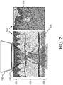
- FIG 2 shows some detail of the LIOB treatment in the Dermis layer 230.
- LIOB treatment targets the Dermis layer 230 such that it affects the skin tissue 200 in order to stimulate re-growth of skin tissue and reduce wrinkles.
- the non-invasive device 100 is able to generate the LIOB phenomenon inside the skin 200 by providing a sequence of the first laser pulse 130 and the second laser pulse 150.
- part of the optical system 160 is shown from which the first laser pulse 130 and the second laser pulse 150 are focused inside the skin 200.
- an optical fluid 165 which typically is used to improve the optical coupling between the optical system 160 and the skin 200.
- Such optical fluid 165 typically has an index of refraction close to that of the skin 200 and a light exit window (not indicated) of the optical system 160 (see Figure 1 ). It has a property whereby it overcomes the microscopic refractive index variations occurring at the skin surface due to vertically stacked corneocytes (not indicated).
- the refractive index of stratum corneum depends strongly on environmental conditions and recent history of the skin tissue 200 as well as on the age and skin care routine of an individual.
- a typical range of stratum corneum refractive index is from 1.47 to 1.5 under normal conditions, which is in the range of natural vegetable oils but slightly higher than that of mineral oils.
- the optical fluid 165 comprises oil 165, water 165 or any other fluid able to improve the optical coupling between the optical system 160 and the skin tissue 200.
- the first light pulse 130 and the subsequent second light pulse 150 are sequentially focused by the optical system 160 into the treatment location 210 in the Dermis layer 230.
- the first laser pulse 130 is configured for initiating a plasma 205 and the subsequent second laser pulse 150 is used to sustain or enhance the plasma 205 to generate LIOB at the treatment location 210.
- the surrounding tissue being the Epidermis layer 220 and the Sub-cutis layer 240 typically is not damaged, as the converging and diverging properties of the focused first light pulse 130 and second light pulse 150 typically have too low an intensity level.
- the right-hand side image in Figure 2 shows part of the skin tissue 200 in which a lesion 235 is shown created using the non-invasive device 100 according to the invention.
- a lesion 235 activates the skin 200 to stimulate re-growth of skin tissue, which will subsequently reduce wrinkles.
- Figure 3 shows the first laser pulse 130 and second laser pulse 150 configured for jointly generating LIOB.
- the example shown in Figure 3 is an oscilloscope reading showing the parameters of the first laser pulse 130 and the second laser pulse 150 used to demonstrate the proof of the principle by creating optical breakdown in water.
- the wavelength ⁇ f of the light of the first laser pulse 130 and the wavelength ⁇ s of the second laser pulse 150 in this case are identical, being 1064 nanometers.
- the first pulse duration of the first laser pulse 130 is between 30 and 100 picoseconds at an overall pulse energy of 0.2 milliJoule for initiating the plasma inside water.
- the second pulse duration of the second laser pulse 150 is 10 to 20 nanoseconds at an overall pulse energy of 5 to 10 milliJoule for feeding the plasma 205 initiated by the first laser pulse 130.
- the time delay ⁇ T between the peak intensity of the first laser pulse 130 and the peak intensity of the second laser pulse 150 is approximately 30 nanoseconds.
- the exact requirements (pulse duration, power density, overall pulse energy and time delay) to generate LIOB using the first laser pulse 130 and the second laser pulse 150 in skin tissue 200 may be different, depending on the depth inside the skin tissue 200 where the LIOB should occur.
- a table (not shown) indicating preferred settings in different situations or treatment depths may be generated, for example, experimentally. Such a table may, for example, be stored in the controller 180 (see Figure 1 ) and used for selecting the preferred settings during operation.
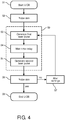
- FIG 4 shows a flow diagram indicating the method and a computer program product configured to perform the method.
- the LIOB process is started.
- the skin tissue 200 may be probed by a feedback system 190 (see Figure 1 ).
- This probing step S2 may be a step during which the skin tissue 200 is analyzed before the skin treatment is started. During such probing step S2, the type of skin tissue 200 may be determined or the depth of wrinkles present in the skin tissue 200 may be determined before the Laser treatment is actually initiated.
- the probing step S2 is an optional step, it may enhance the overall quality of the skin treatment, as it enables the non-invasive device 100 to determine, for example, the characteristics of the first laser pulse 130 and the subsequent second laser pulse 150 to ensure that the LIOB treatment will be effective without, for example, damaging the upper dermis layer 220 (see Figure 2 ).
- the first laser pulse 130 is generated after which the controller 180 waits for a predetermined time delay ⁇ T in step S4, after which, in step S5, the second laser pulse 150 is generated.
- This generation of the first laser pulse 130 may, for example, be done using the first laser 120 and the generation of the second laser pulse 150 may, for example, be done using the second laser 140.
- steps S3, S4 and S5 cover LIOB step S9 covering the initiation of the plasma 205 (see Figure 1 ), and the sustainment or enhancement of the plasma 205 to create the LIOB.
- the skin tissue 200 may again be probed.
- this probing of the skin tissue 200 may again be an optional step S6, for example, to determine an efficiency of the overall LIOB treatment and to determine whether or not to continue with the LIOB treatment.
- the settings of the non-invasive device 100 may be altered in step S7 and the first laser pulse 130 may again be initiated in step S3 to redo the LIOB treatment at different settings.
- the LIOB treatment may be redone without changing the settings of the non-invasive device 100 - so the sequence may be re-initiated in step S3 without different settings being applied in step S7.
- the LIOB process may be ended at step S8.
- the disclosure also extends to computer programs, particularly computer programs on or in a carrier, adapted for putting the invention into practice.
- the program may be in the form of source code, object code, a code intermediate source and object code such as a partially compiled form, or in any other form suitable for use in the implementation of the described method.
- a program may have many different architectural designs.
- a program code implementing the functionality of the method or system may be subdivided into one or more subroutines. Many different ways to distribute the functionality among these subroutines will be apparent to the skilled person.
- the subroutines may be stored together in one executable file to form a self-contained program.
- Such an executable file may comprise computer-executable instructions, for example processor instructions and/or interpreter instructions (e.g. Java interpreter instructions).
- one or more or all of the subroutines may be stored in at least one external library file and linked with a main program either statically or dynamically, e.g. at run-time.
- the main program contains at least one call to at least one of the subroutines.
- the subroutines may comprise function calls to each other.
- An embodiment relating to a computer program product comprises computer-executable instructions corresponding to each of the processing steps of at least one of the methods set forth. These instructions may be subdivided into subroutines and/or stored in one or more files that may be linked statically or dynamically.
- Another embodiment relating to a computer program product comprises computer-executable instructions corresponding to each of the means of at least one of the systems and/or products set forth. These instructions may be subdivided into subroutines and/or stored in one or more files that may be linked statically or dynamically.
- the carrier of a computer program may be any entity or device capable of carrying the program.
- the carrier may include a storage medium, such as a ROM, for example a CD ROM or a semiconductor ROM, or a magnetic recording medium, for example a floppy disc or hard disk.
- the carrier may be a transmissible carrier such as an electrical or optical signal, which may be conveyed via electrical or optical cable or by radio or other means.
- the carrier may be constituted by such a cable or other device or means.
- the carrier may be an integrated circuit in which the program is embedded, the integrated circuit being adapted for performing, or for use in the performance of, the relevant method.
Description
- This invention relates to a non-invasive device for treatment of skin tissue using laser light.
- Such non-invasive skin treatment device is, e.g., known from the published international patent application
WO 2008/001284 A2 . Said application discloses a skin treatment device with a laser source and focusing optics. The device creates a focal spot in a dermis layer of the skin to be treated. The power of the laser is selected such that laser-induced optical breakdown (LIOB) affects the skin in order to stimulate re-growth of skin tissue and reduce wrinkles. - The device is able to provide a laser-induced optical breakdown (LIOB) phenomenon in the skin by providing sufficiently intense laser pulses. This LIOB is based on strong non-linear absorption of the laser light by the skin tissue, which occurs above a certain threshold value for the power density of the laser light. This strong absorption causes a very localized plasma that is able to damage or even remove tissue at the location of said plasma. The effect is local, because below the threshold there is zero or very little linear and non-linear absorption, while above the threshold a plasma is generated.
- LIOB occurs inside the skin tissue when the light intensity is sufficiently high to produce a critical free-electron density, which is about 1021cm-3. To generate such high intensity locally inside the skin, the requirements on the light source to create LIOB are relatively high.
-
WO 2012/107830 discloses a system for treating a region of the epidermis, comprising at least one laser energy source, a time control device to generate a laser beam, and a laser energy focusing system arranged and produced to direct a laser beam on said region of the epidermis. The control device generates a laser beam comprising a plurality of composite pulses, emitted at a base frequency, each composite pulse comprising a sequence of sub-pulses at a higher frequency than said base frequency. In an embodiment each composite pulse comprises a pre-pulse of greater duration and a train of sub-pulses of lesser duration. The pre-pulse has an energy per unit of surface area such as to generate plasma to remove the epidermis but such as not to interact with the middle layers of the dermis. The sub-pulses have an energy per unit of surface area adapted to generate a cold ablation, i.e. without plasma or substantially without plasma. - It is an object of the invention to provide a device for light-based skin treatment in which the requirements on the light source are reduced.
- A first aspect of the invention provides a non-invasive device for treatment of skin using laser light.
- The non-invasive device for treatment of skin according to the first aspect of the invention comprises a light emission system for generating a first laser pulse and a subsequent second laser pulse at a predefined time delay after the first laser pulse. The non-invasive device further comprises an optical system for focusing, in use, the first laser pulse and the second laser pulse into a focal spot at a treatment location inside the skin tissue. The first laser pulse has a first power density (W/cm2) in the focal spot, a first pulse duration and a first pulse energy (mJ) for initiating a plasma in the skin tissue at the treatment location. The subsequent second laser pulse has a second power density in the focal spot being lower than the first power density, a second pulse duration and a second pulse energy. According to the invention the first pulse duration is in a range between 1 and 1,000 picoseconds, the second pulse duration is at least 10 times longer than the first pulse duration and is in a range between 1 and 1,000 nanoseconds, the time delay is in a range between 1 nanosecond and 10 microseconds, the first pulse energy is in a range between 0.1 and 2 mJ, the second pulse energy is 10 to 100 times higher than the first pulse energy and is in a range between 1 and 200 mJ for sustaining or intensifying, by generating the second laser pulse at said predefined time delay after the first laser pulse, the plasma initiated by the first laser pulse by absorption of at least part of the energy of the second laser pulse by the plasma initiated by the first laser pulse to generate breakdown of the skin tissue in the treatment location. It is in this manner that, in use, the first laser pulse and the second laser pulse together generate Laser-Induced Optical Breakdown at the treatment location.
- The use of two laser pulses to generate Laser-Induced Optical Breakdown (further also indicated as LIOB) relaxes the boundary conditions of the light emission system significantly. The first laser pulse creates a plasma at the treatment location inside the skin tissue, and the second laser pulse sustains or even enhances (or feeds) this plasma created by the first laser pulse. This combination of the first laser pulse and the second laser pulse creates a sufficiently high electron density at the treatment location to generate LIOB. In the known non-invasive LIOB system, LIOB is usually produced using a single laser pulse. A laser source capable to produce this single laser pulse in the known LIOB system must be able to produce a relatively short laser pulse (pulse duration less than 1,000 picoseconds) having a relatively high energy (up to 10 mJ). This combination of requirements to generate the single laser pulse in the known non-invasive LIOB system causes the known laser source to be relatively bulky, such as an industrially used Nd:YAG laser source. Using such a laser source in the known non-invasive LIOB systems makes the known LIOB systems relatively expensive and causes the operation of such LIOB system to require specialists that know how to operate such a high-power laser source. The inventors have found that, by splitting up the LIOB generation between the first laser pulse and the second laser pulse, the boundary conditions of each of the first laser pulse and the second laser pulse may be relaxed significantly such that also the requirements on the light emission system may be relaxed significantly, thereby reducing the overall cost of the non-invasive skin treatment device significantly. For example, the light emission system may comprise two different laser sources which produce, respectively, the first laser pulse and the subsequent second laser pulse. The first pulse duration (or first pulse width) of the first laser pulse may, for example, be 10 times shorter than the second pulse duration (or second pulse width), or even up to 500 to 1,000 times shorter than the second pulse duration (or second pulse width) of the second laser pulse. The first pulse duration or first pulse width and the second pulse duration or second pulse width are typically measured at the Full-Width-Half-Maximum (further also indicted as FWHM) of the first laser pulse and second laser pulse, respectively. The first power density of the first pulse is higher than the second power density of the second pulse, while the overall energy of the second laser pulse is 10 to 100 times higher than the energy of the first laser pulse. Because the requirements for the first laser pulse and the second laser pulse are so different, the two different laser sources may be specifically tuned to produce these first laser pulses and second laser pulses, which results in a more cost-effective solution. But, in addition to a reduction in costs, the non-invasive device may also become less bulky, which may also be an important aspect for the consumer market. Furthermore, the device may be able to be operated by non-specialists, because the individual laser power to produce the first laser pulse and the second laser pulse is significantly less than the laser power required for the single laser pulse LIOB generation, which is approximately a factor of 20 higher than the highest power of the first laser pulse or the second laser pulse.
- This reduction in individual laser power to produce the first laser pulse and the second laser pulse in the non-invasive device according to the invention has the further benefit that it reduces any possible damage to the skin tissue, which would be due to the treatment of the skin using such high power laser light, and that it reduces any possible damage of optical elements guiding the first laser pulse and the second laser pulse to the skin tissue.
- In the non-invasive device according to the invention, the second laser pulse is emitted at the predefined time delay after the first laser pulse, wherein the time delay is in a range between 1 nanosecond and10 microseconds. A benefit of delaying the second laser pulse after the first laser pulse is that the absorption efficiency of the second laser pulse by the plasma generated by the first laser pulse is improved. Because some time is required for the first laser pulse to generate the plasma at the treatment location, the delay of the second laser pulse will ensure that the second laser pulse arrives at the treatment location when the plasma is 'ready' to absorb the radiation of the second laser pulse. The exact time delay required to achieve the highest efficiency may be experimentally determined and may differ depending on the depth inside the skin where the treatment location is located.
- The time delay is typically measured from a maximum intensity of the first laser pulse to a maximum intensity of the second laser pulse. Therefore, the first laser pulse and the second laser pulse may partially overlap. As indicated before, the effect of the time delay is that the efficiency of the absorption of the light of the second light pulse by the plasma is enhanced due to the fact that some time is required for the first light pulse to generate the plasma inside the skin tissue. Again, the exact value of the time delay required to achieve the highest efficiency may be experimentally determined and may differ depending on the depth inside the skin where the treatment location is located.
- In an embodiment of the non-invasive device according to the invention, a wavelength of the second laser pulse is selected to generate off-resonance absorption of the energy of the second laser pulse by the plasma at the treatment location to sustain or intensify the plasma initiated by the first laser pulse. Or, put differently, the non-invasive device according to the invention is configured for emitting a wavelength of the second laser pulse which is selected to be included in an absorption peak of Inverse Bremsstrahlung of the plasma created by the first laser pulse. The second laser pulse may even enhance (or feed) the plasma created by the first laser pulse - as already mentioned before. Such off-resonance absorption is different from the on-resonance absorption where the wavelength of the plasma feeding light is tuned to the peak resonance absorption of the excited target atoms used, for example, for ablation. On-resonance absorption requires critical pulse parameters matching the energy levels of the target atoms or molecules. The energy is transferred to the targeted atoms, not to the plasma itself. In the current embodiment, off-resonance absorption is used for which substantially the only restriction to the wavelength of the second laser pulse is that the laser pulse efficiently reaches the plasma inside the skin tissue, initiated by the first laser pulse.
- In an embodiment of the non-invasive device, the first laser pulse comprises polarized light. To be able to efficiently initiate a plasma at the treatment location inside the skin tissue, polarized laser light may be used. By choosing the first laser pulse to be a polarized first laser pulse, the efficiency of the initiation of the plasma at the treatment location inside the skin tissue may be further improved - allowing the peak intensity or peak power density of the first laser pulse to be further reduced. The subsequent, second laser pulse is used for sustaining or feeding the initiated plasma and there is no real benefit when this second laser pulse is polarized. In an embodiment of the non-invasive device, the wavelength of the first laser pulse is approximately 1064 nanometers. The wavelength of the second laser pulse may be any wavelength that reaches the plasma inside the skin.
- In an embodiment of the non-invasive device, the light emission system comprises a first laser for emitting the first laser pulse and comprises a second laser for emitting the second laser pulse, the second laser being different from the first laser. As indicated before, the first laser pulse is different from the second laser pulse. Due to the use of the first laser pulse and the subsequent, second laser pulse, the individual requirements on each of the first laser pulse and the second laser pulse have already been reduced. As a result, the light emission system may already have relaxed boundary conditions in case the light is generated using a single laser. However, when using the first laser to generate the first laser pulse and the second laser to generate the second laser pulse, the first laser and the second laser may be specifically tuned to produce these first laser pulses and second laser pulses, respectively, which results in a more cost-effective solution.
- In an embodiment of the non-invasive device, the treatment location is in a dermis layer of the skin, below the epidermis layer. Therefore, the wavelength used for the first laser pulse and the second laser pulse should reach this dermis layer inside the skin and should have sufficient intensity or power density at this dermis layer to ensure that the first laser pulse initiates the plasma and that the second laser pulse sustains or enhances (or feeds) the plasma sufficiently to generate enough critical free-electron density to achieve LIOB.
- In an embodiment of the non-invasive device, the non-invasive device comprises a feedback system for determining a focusing depth of the first laser pulse and/or the second laser pulse at the treatment location. Such a feedback system may, for example, be configured for measuring a Second Harmonic Generated signal (further also indicated as SHG signal) reflected from the treatment location. This SHG signal may be a measure of the collagen content present at the treatment location and so the SHG signal measured may be used to see whether the optical system focuses inside the dermis layer. Collagen strains present in the dermis layer have birefringent characteristics, such that when hit by light, they reflect part of the light as a SHG signal. So, the measuring of the SHG signal may be used to determine whether the optical system focuses at the correct depth inside the skin. The SHG signal may be created using a further light source in the non-invasive device according to the invention. Alternatively, the SHG signal may be created using, for example, part of the impinging second laser pulse. According to an alternative method, the focusing depth is determined using polarization-sensitive birefringent detection for detecting the collagen strains in the dermis layer. Of course any other known feedback system for determining a focusing depth inside the skin may be used.
- In an embodiment of the non-invasive device, the non-invasive device comprises a feedback system for detecting the plasma inside the skin tissue and/or for detecting an acoustic signal generated during the Laser-Induced Optical Breakdown at the treatment location. Detecting the plasma inside the skin tissue may, for example, be done by an optical detector, which detects light of a different wavelength than the wavelength of any of the first laser pulse and the second laser pulse, as the plasma will emit light in a very broad wavelength range. Detection of the presence of the plasma is an indicator of the efficiency of the LIOB. Alternatively, the feedback system may comprise an acoustic detector to detect the acoustic signal generated during LIOB. Due to the rapid initiation of the plasma and the creation of lesions, an acoustic wave will propagate through the skin tissue which may be detected using an acoustic detector and which may be used as a measure of the effectiveness of the LIOB process.
- The method of skin treatment using laser, not being part of the invention, comprises the steps of:
- generating a first laser pulse,
- generating a subsequent, second laser pulse different from the first laser pulse and at a predefined time delay after the first laser pulse, and
- focusing the first laser pulse and the second laser pulse into a focal spot at a treatment location inside skin tissue.
- The first laser pulse has a first power density (W/cm2) in the focal spot, a first pulse duration, and a first pulse energy for initiating a plasma in the skin tissue at the treatment location. The subsequent second laser pulse has a second power density in the focal spot being lower than the first power density, a second pulse duration and a second pulse energy. According to the invention the first pulse duration is in a range between 1 and 1,000 picoseconds, the second pulse duration is at least 10 times longer than the first pulse duration and is in a range between 1 and 1,000 nanoseconds, the time delay is in a range between 1 nanosecond and 10 microseconds, the first pulse energy is in a range between 0.1 and 2 mJ, the second pulse energy is 10 to 100 times higher than the first pulse energy and is in a range between 1 and 200 mJ for sustaining or intensifying, by generating the second laser pulse at said predefined time delay after the first laser pulse, the plasma initiated by the first laser pulse by absorption of at least part of the energy of the second laser pulse by the plasma initiated by the first laser pulse to generate breakdown of the skin tissue in the treatment location.
- Thus, in use, the first laser pulse and the second laser pulse together generate Laser-Induced Optical Breakdown at the treatment location. As mentioned already hereinabove, the second laser pulse may also enhance or feed the plasma generated by the first laser pulse.
- In the method, the first laser pulse is generated by a first laser and the second laser pulse is generated by a second laser different from the first laser.
- These and other aspects of the invention are apparent from and will be elucidated with reference to the embodiments described hereinafter.
- In the drawings:
-
Figure 1 schematically shows a non-invasive device according to the invention, -
Figure 2 shows some detail of the LIOB treatment in the Dermis layer, -
Figure 3 shows the first laser pulse and the second laser pulse configured for jointly generating LIOB, and -
Figure 4 shows a flow diagram indicating the method not being part of the invention and a computer program product configured to perform the method. -
Figure 1 schematically shows anon-invasive device 100 according to the invention. Thenon-invasive device 100 comprises alight emission system 110 for generating afirst laser pulse 130 and a subsequentsecond laser pulse 150. Thenon-invasive device 100 further comprises anoptical system 160, for example, a microscope objective 10 or anyother lens element 160 for focusing thefirst laser pulse 130 and thesecond laser pulse 150 into a focal spot at atreatment location 210 inside theskin tissue 200. Thefirst laser pulse 130 has a relatively high first power density (W/cm2) in the focal spot, a relatively short first pulse duration (illustrated by means of the pulse shape indicated by reference number 130) and a first pulse energy. Thefirst laser pulse 130 is configured such that a plasma is initiated in theskin tissue 200 in the focal spot at thetreatment location 210. Thesecond laser pulse 150 has a relatively low power density (W/cm2) in the focal spot, a relatively long second pulse duration (illustrated by means of the pulse shape indicated by reference number 150), and a relatively high pulse energy. Thesecond laser pulse 150 is configured for sustaining or feeding (or enhancing) the plasma initiated at the same treatment location by thefirst laser pulse 130 to create a sufficiently high free-electron density at thetreatment location 210 to generate Laser-Induced Optical Breakdown (further also indicated as LIOB). For this purpose, thesecond laser pulse 150 is generated at a sufficiently short predefined time delay after the first laser pulse, such that after said time delay the plasma initiated by thefirst laser pulse 130 is still present and able to absorp the energy of thesecond laser pulse 150. The use of thefirst laser pulse 130 together with the subsequentsecond laser pulse 150 to generate LIOB relaxes the boundary conditions of thelight emission system 110 significantly. In a known non-invasive LIOB system, LIOB is usually produced using a single laser pulse. This single laser pulse in the known LIOB system has a relatively short laser pulse duration (pulse duration less than 1,000 picoseconds) while having a relatively high energy (up to 10 milli-Joules). This combination of requirements to generate the single laser pulse in the known non-invasive LIOB system causes the known laser source to be relatively bulky and expensive (applicable laser source may, for example, be an Nd:YAG laser source). Furthermore, such a high-power laser source in the known non-invasive LIOB system typically requires a specialist who knows how to operate such a laser source. The inventor has found that when the LIOB generation is split up between thefirst laser pulse 130 and thesecond laser pulse 150, the boundary conditions of each of thefirst laser pulse 130 and thesecond laser pulse 150 may be relaxed significantly such that also the requirements on thelight emission system 110 may be relaxed significantly. This relaxation of the requirements on thelight emission system 110 also reduces the cost of thenon-invasive device 100 and may enable thenon-invasive device 100 according to the invention to be operated bynon-specialists. A specific range of requirements on thefirst laser pulse 130 and thesecond laser pulse 150 such that LIOB may be efficiently induced inside the Dermis layer 230 (seeFigure 2 ) may be found in Table 1 hereinbelow.Table 1: overview of requirements on the single laser pulse LIOB and the LIOB solution using the first laser pulse 130 and thesecond laser pulse 150.Single laser pulse LIOB LIOB using the first laser pulse and the second laser pulse Laser pulse First laser pulse (Plasma ignition) Second laser pulse (Plasma feeding) Wavelength 1064 nm 1064 nm Any wavelengths that could reach the plasma source generated inside the skin Pulse duration 1-200 ps 1-1000 ps 1-1000 ns Pulse energy 1-20 mJ 0.1-2 mJ 1-200 mJ Mode profile Single mode Single mode / Multi-mode Single mode / Multi mode - In Table 1, the pulse duration range of the first laser pulse is relatively broad compared to the single laser pulse LIOB, while the overall pulse energy is relatively low compared to the single laser pulse LIOB. The correct combination of first laser pulse duration and overall pulse energy must be chosen to ensure that a
plasma 205 will be initiated. For example, the inventors have found in experiments that the use of a first laser pulse having a pulse duration of, for example, 1,000 picoseconds with an overall pulse energy of 0.1 milliJoule will initiate aplasma 205, however this initiatedplasma 205 may be a relatively low-density plasma without associated breakdown and lesion formation inside the skin tissue. The second laser pulse is required to enhance and feed theplasma 205 to ensure that LIOB occurs at thetreatment location 210 inside theskin tissue 200. - The
light emission system 110 may, for example, comprise afirst laser source 120 emitting thefirst laser pulse 130 and may, for example, comprise asecond laser source 140 emitting thesecond laser pulse 150. The first pulse duration (or first pulse width) of thefirst laser pulse 130, for example, is 10 times shorter, or even much more shorter, such as 500 to 1,000 times shorter, compared to the second pulse duration (or second pulse width) of thesecond laser pulse 150, while the overall pulse energy of thesecond laser pulse 150 is 10 to 100 times higher than the overall pulse energy of thefirst laser pulse 130. An example of a possiblefirst laser pulse 130 and asecond laser pulse 150 is shown inFigure 3 in which LIOB is demonstrated in water using two pulses. Because the requirements for thefirst laser pulse 130 and thesecond laser pulse 150 are so different, thefirst laser source 120 and thesecond laser source 140 may be specifically tuned to produce thesefirst laser pulses 130 andsecond laser pulses 150, which results in a more cost-effective solution. - So, by using the
light emission system 110 according to the invention, a reduction will be achieved of the maximum power and power density of the individualfirst laser pulse 130 andsecond laser pulse 150 necessary to generate the LIOB, compared to the laser pulse in the known non-invasive LIOB system. This reduction in individual laser power and power density also reduces any possible damage of the upper layers of the skin 200 (for example, theepidermis 220 layer - seeFigure 2 ) due to the treatment of theskin 200. Furthermore, the reduction of the maximum power and power density of thefirst laser pulse 130 and thesecond laser pulse 150 reduces any possible damage ofoptical elements first laser pulse 130 and thesecond laser pulse 150 to theskin 200. - The wavelength λf of the
first laser pulse 130 may, for example, be 1064 nanometer, as light of this wavelength penetrates deeply into theskin 200. The wavelength λs of thesecond laser pulse 150 may comprise any wavelength that reaches theplasma 205 generated by thefirst laser pulse 130 and that sustains or feeds theplasma 205 to create the LIOB. This sustaining or feeding of theplasma 205 by thesecond laser pulse 150 may be done via off-resonance absorption or by tuning thesecond laser pulse 150 to emit light having a wavelength which is selected to be included in an absorption peak of Inverse Bremsstrahlung of theplasma 205 initiated by thefirst laser pulse 130. - In the
non-invasive device 100 according to the invention, thesecond laser pulse 150 is emitted at the predefined time delay ΔT after thefirst laser pulse 130. Due to this time delay ΔT, the efficiency of the absorption of thesecond laser pulse 150 by theplasma 205 initiated by thefirst laser pulse 130 is improved. When thefirst laser pulse 130 impinges on thetreatment location 210, some time is required for theplasma 205 to be initiated at thetreatment location 210. The time delay ΔT of thesecond laser pulse 150 relative to thefirst laser pulse 130 ensures that thesecond laser pulse 150 arrives at thetreatment location 210 when theplasma 205 is 'ready' to absorb the radiation of thesecond laser pulse 150. The exact time delay ΔT required to achieve the highest efficiency may be experimentally established and may differ depending on skin type and depth inside the skin tissue where thetreatment location 210 is located. - The
non-invasive device 100 as shown inFigure 1 also comprisesoptical elements first laser pulse 130 and thesecond laser pulse 150 to thetreatment location 210. As indicated before, one of theoptical elements optical system 160 for focusing thefirst laser pulse 130 and thesecond laser pulse 150 into theskin tissue 200. Suchoptical system 160 may be, for example, amicroscope objective 160. A further optical element may be, for example, asemi-transparent mirror element 170 to combine thefirst laser pulse 130 emitted by thefirst laser 120 with thesecond laser pulse 150 emitted by thesecond laser 140, such that they may use the sameoptical system 160. In addition to the two indicatedoptical elements non-invasive device 100 may comprise other optical elements to shape and guide thefirst laser pulse 130 and thesecond laser pulse 150 to thetreatment location 210 inside theskin tissue 200. - The
non-invasive device 100 as shown inFigure 1 further comprises acontroller 180 for controlling thelight emission system 110, for example, comprising thefirst laser 120 and thesecond laser 140, and it further comprises afeedback system 190 for providing some feedback signal to the controller 180 (indicated inFigure 1 by means of the curved arrow going from thefeedback system 190 to the controller 180). Thecontroller 180 may, for example, determine the first pulse duration and the first power density of thefirst laser pulse 130 and the second pulse duration and the second power density of thesecond laser pulse 150, for example, to prevent damage to the upper layers of theskin tissue 200 during the non-invasive skin treatment. Thecontroller 180 may also determine the time delay ΔT between thefirst laser pulse 130 and thesecond laser pulse 150 to further increase the efficiency of the generation of the LIOB by timing the time delay ΔT such that substantially all of thesecond laser pulse 150 is absorbed by theplasma 205. Thecontroller 180 may also use the feedback signal of thefeedback system 190 to determine, for example, the efficiency of the LIOB, initial damage to the upper layers of theskin tissue 200, and increased temperature of the upper layer of theskin tissue 200 or any other parameter useful to control thenon-invasive device 100 according to the invention. -
Figure 2 shows some detail of the LIOB treatment in theDermis layer 230. LIOB treatment targets theDermis layer 230 such that it affects theskin tissue 200 in order to stimulate re-growth of skin tissue and reduce wrinkles. Thenon-invasive device 100 is able to generate the LIOB phenomenon inside theskin 200 by providing a sequence of thefirst laser pulse 130 and thesecond laser pulse 150. InFigure 2 , part of theoptical system 160 is shown from which thefirst laser pulse 130 and thesecond laser pulse 150 are focused inside theskin 200. Also indicated inFigure 2 is anoptical fluid 165 which typically is used to improve the optical coupling between theoptical system 160 and theskin 200. Suchoptical fluid 165 typically has an index of refraction close to that of theskin 200 and a light exit window (not indicated) of the optical system 160 (seeFigure 1 ). It has a property whereby it overcomes the microscopic refractive index variations occurring at the skin surface due to vertically stacked corneocytes (not indicated). The refractive index of stratum corneum depends strongly on environmental conditions and recent history of theskin tissue 200 as well as on the age and skin care routine of an individual. A typical range of stratum corneum refractive index is from 1.47 to 1.5 under normal conditions, which is in the range of natural vegetable oils but slightly higher than that of mineral oils. So, theoptical fluid 165 comprisesoil 165,water 165 or any other fluid able to improve the optical coupling between theoptical system 160 and theskin tissue 200. Thefirst light pulse 130 and the subsequent secondlight pulse 150 are sequentially focused by theoptical system 160 into thetreatment location 210 in theDermis layer 230. Thefirst laser pulse 130 is configured for initiating aplasma 205 and the subsequentsecond laser pulse 150 is used to sustain or enhance theplasma 205 to generate LIOB at thetreatment location 210. When the light is focused inside theDermis layer 230, the surrounding tissue being theEpidermis layer 220 and theSub-cutis layer 240 typically is not damaged, as the converging and diverging properties of the focusedfirst light pulse 130 and secondlight pulse 150 typically have too low an intensity level. - The right-hand side image in
Figure 2 shows part of theskin tissue 200 in which alesion 235 is shown created using thenon-invasive device 100 according to the invention. Such alesion 235 activates theskin 200 to stimulate re-growth of skin tissue, which will subsequently reduce wrinkles. -
Figure 3 shows thefirst laser pulse 130 andsecond laser pulse 150 configured for jointly generating LIOB. The example shown inFigure 3 is an oscilloscope reading showing the parameters of thefirst laser pulse 130 and thesecond laser pulse 150 used to demonstrate the proof of the principle by creating optical breakdown in water. The wavelength λf of the light of thefirst laser pulse 130 and the wavelength λs of thesecond laser pulse 150 in this case are identical, being 1064 nanometers. The first pulse duration of thefirst laser pulse 130 is between 30 and 100 picoseconds at an overall pulse energy of 0.2 milliJoule for initiating the plasma inside water. The second pulse duration of thesecond laser pulse 150 is 10 to 20 nanoseconds at an overall pulse energy of 5 to 10 milliJoule for feeding theplasma 205 initiated by thefirst laser pulse 130. As can be seen fromFigure 3 , the time delay ΔT between the peak intensity of thefirst laser pulse 130 and the peak intensity of thesecond laser pulse 150 is approximately 30 nanoseconds. As indicated before, the exact requirements (pulse duration, power density, overall pulse energy and time delay) to generate LIOB using thefirst laser pulse 130 and thesecond laser pulse 150 inskin tissue 200 may be different, depending on the depth inside theskin tissue 200 where the LIOB should occur. A table (not shown) indicating preferred settings in different situations or treatment depths may be generated, for example, experimentally. Such a table may, for example, be stored in the controller 180 (seeFigure 1 ) and used for selecting the preferred settings during operation. -
Figure 4 shows a flow diagram indicating the method and a computer program product configured to perform the method. At a first step S1, the LIOB process is started. Next, at step S2 theskin tissue 200 may be probed by a feedback system 190 (seeFigure 1 ). This probing step S2 may be a step during which theskin tissue 200 is analyzed before the skin treatment is started. During such probing step S2, the type ofskin tissue 200 may be determined or the depth of wrinkles present in theskin tissue 200 may be determined before the Laser treatment is actually initiated. Although the probing step S2 is an optional step, it may enhance the overall quality of the skin treatment, as it enables thenon-invasive device 100 to determine, for example, the characteristics of thefirst laser pulse 130 and the subsequentsecond laser pulse 150 to ensure that the LIOB treatment will be effective without, for example, damaging the upper dermis layer 220 (seeFigure 2 ). Next, in step S3, thefirst laser pulse 130 is generated after which thecontroller 180 waits for a predetermined time delay ΔT in step S4, after which, in step S5, thesecond laser pulse 150 is generated. This generation of thefirst laser pulse 130 may, for example, be done using thefirst laser 120 and the generation of thesecond laser pulse 150 may, for example, be done using thesecond laser 140. Together, steps S3, S4 and S5 cover LIOB step S9 covering the initiation of the plasma 205 (seeFigure 1 ), and the sustainment or enhancement of theplasma 205 to create the LIOB. Subsequently, in step S6 theskin tissue 200 may again be probed. Also, this probing of theskin tissue 200 may again be an optional step S6, for example, to determine an efficiency of the overall LIOB treatment and to determine whether or not to continue with the LIOB treatment. For example, when the LIOB treatment was not sufficient or when the LIOB treatment was not effective (indicated by the arrow comprising 'N'), the settings of the
non-invasive device 100 may be altered in step S7 and thefirst laser pulse 130 may again be initiated in step S3 to redo the LIOB treatment at different settings. If the LIOB treatment was not sufficient, the LIOB treatment may be redone without changing the settings of the non-invasive device 100 - so the sequence may be re-initiated in step S3 without different settings being applied in step S7. Alternatively, when the LIOB treatment was sufficient and effective (indicated by the arrow comprising 'Y'), the LIOB process may be ended at step S8. - It will be appreciated that the disclosure also extends to computer programs, particularly computer programs on or in a carrier, adapted for putting the invention into practice. The program may be in the form of source code, object code, a code intermediate source and object code such as a partially compiled form, or in any other form suitable for use in the implementation of the described method. It will also be appreciated that such a program may have many different architectural designs. For example, a program code implementing the functionality of the method or system may be subdivided into one or more subroutines. Many different ways to distribute the functionality among these subroutines will be apparent to the skilled person. The subroutines may be stored together in one executable file to form a self-contained program. Such an executable file may comprise computer-executable instructions, for example processor instructions and/or interpreter instructions (e.g. Java interpreter instructions). Alternatively, one or more or all of the subroutines may be stored in at least one external library file and linked with a main program either statically or dynamically, e.g. at run-time. The main program contains at least one call to at least one of the subroutines. Also, the subroutines may comprise function calls to each other. An embodiment relating to a computer program product comprises computer-executable instructions corresponding to each of the processing steps of at least one of the methods set forth. These instructions may be subdivided into subroutines and/or stored in one or more files that may be linked statically or dynamically. Another embodiment relating to a computer program product comprises computer-executable instructions corresponding to each of the means of at least one of the systems and/or products set forth. These instructions may be subdivided into subroutines and/or stored in one or more files that may be linked statically or dynamically.
- The carrier of a computer program may be any entity or device capable of carrying the program. For example, the carrier may include a storage medium, such as a ROM, for example a CD ROM or a semiconductor ROM, or a magnetic recording medium, for example a floppy disc or hard disk. Further, the carrier may be a transmissible carrier such as an electrical or optical signal, which may be conveyed via electrical or optical cable or by radio or other means. When the program is embodied in such a signal, the carrier may be constituted by such a cable or other device or means. Alternatively, the carrier may be an integrated circuit in which the program is embedded, the integrated circuit being adapted for performing, or for use in the performance of, the relevant method.
- It should be noted that the above-mentioned embodiments illustrate rather than limit the invention, and that those skilled in the art will be able to design many alternative embodiments without departing from the scope of the appended claims. In the claims, any reference signs placed between parentheses shall not be construed as limiting the claim. Use of the verb "comprise" and its conjugations does not exclude the presence of elements or steps other than those stated in a claim. The article "a" or "an" preceding an element does not exclude the presence of a plurality of such elements. The invention may be implemented by means of hardware comprising several distinct elements, and by means of a suitably programmed computer. In the device claim enumerating several means, several of these means may be embodied by one and the same item of hardware. The mere fact that certain measures are recited in mutually different dependent claims does not indicate that a combination of these measures cannot be used to advantage.
Claims (7)
- A non-invasive device (100) for treatment of skin tissue (200) using laser light, the device comprising:a light emission system (110) for generating a first laser pulse (130) and a subsequent second laser pulse (150) at a predefined time delay (ΔT) after the first laser pulse (130),an optical system (160) for focusing the first laser pulse (130) and the second laser pulse (150) into a focal spot at a treatment location (210) inside the skin tissue (200), the first laser pulse (130) having a first power density (W/cm2) in the focal spot, a first pulse duration (ms) and a first pulse energy (mJ) for initiating a plasma (205) in the skin tissue at the treatment location (210), the subsequent, second laser pulse (150) having a second power density in the focal spot being lower than the first power density, a second pulse duration and a second pulse energy,characterized in that the first pulse duration is in a range between 1 and 1,000 picoseconds, the second pulse duration is at least 10 times longer than the first pulse duration and is in a range between 1 and 1,000 nanoseconds, the time delay (ΔT) is in a range between 1 nanosecond and 10 microseconds, the first pulse energy is in a range between 0.1 and 2 mJ, the second pulse energy is 10 to 100 times higher than the first pulse energy and is in a range between 1 and 200 mJ for sustaining or intensifying, by generating the second laser pulse at said predefined time delay after the first laser pulse, the plasma (205) initiated by the first laser pulse (130) by absorption of at least part of the energy of the second laser pulse (150) by the plasma initiated by the first laser pulse (130) to generate breakdown of the skin tissue (200) in the treatment location, whereby the first laser pulse (130) and the second laser pulse (150) together generate Laser Induced Optical Breakdown at the treatment location (210).
- The non-invasive device (100) as claimed in claim 1, wherein a wavelength (λs) of the second laser pulse (150) is selected to be included in an absorption peak of Inverse Bremsstrahlung of the plasma (205) initiated by the first laser pulse (130) at the treatment location (210) to sustain or intensify the plasma (205) initiated by the first laser pulse (130).
- The non-invasive device (100) as claimed in claim 1, wherein the first laser pulse (130) comprises polarized light.
- The non-invasive device (100) as claimed in claim 1, wherein the light emission system (110) comprises a first laser (120) for emitting the first laser pulse (130) and comprises a second laser (140) for emitting the second laser pulse (150), the second laser (140) being different from the first laser (120).
- The non-invasive device (100) as claimed in claim 1, wherein the treatment location (210) is in a dermis layer (230) of skin.
- The non-invasive device (100) as claimed in claim 1, wherein the non-invasive device (100) comprises a feedback system (190) for determining a focusing depth of the first laser pulse (130) and/or the second laser pulse (150) at the treatment location (210).
- The non-invasive device (100) as claimed in claim 1, wherein the non-invasive device (100) comprises a feedback system (190) for detecting the plasma (205) inside the skin tissue (200) and/or for detecting an acoustic signal generated during the Laser Induced Optical Breakdown at the treatment location (210).
Priority Applications (1)
| Application Number | Priority Date | Filing Date | Title |
|---|---|---|---|
| EP14719317.1A EP2988693B1 (en) | 2013-04-25 | 2014-04-24 | Non-invasive device for treatment of the skin using laser light |
Applications Claiming Priority (3)
| Application Number | Priority Date | Filing Date | Title |
|---|---|---|---|
| EP13165305 | 2013-04-25 | ||
| PCT/EP2014/058335 WO2014174010A1 (en) | 2013-04-25 | 2014-04-24 | Non-invasive device for treatment of the skin using laser light |
| EP14719317.1A EP2988693B1 (en) | 2013-04-25 | 2014-04-24 | Non-invasive device for treatment of the skin using laser light |
Publications (2)
| Publication Number | Publication Date |
|---|---|
| EP2988693A1 EP2988693A1 (en) | 2016-03-02 |
| EP2988693B1 true EP2988693B1 (en) | 2019-06-12 |
Family
ID=48190742
Family Applications (1)
| Application Number | Title | Priority Date | Filing Date |
|---|---|---|---|
| EP14719317.1A Active EP2988693B1 (en) | 2013-04-25 | 2014-04-24 | Non-invasive device for treatment of the skin using laser light |
Country Status (7)
| Country | Link |
|---|---|
| US (1) | US11129675B2 (en) |
| EP (1) | EP2988693B1 (en) |
| JP (1) | JP6396994B2 (en) |
| CN (1) | CN105142559B (en) |
| BR (1) | BR112015026692A2 (en) |
| RU (1) | RU2652746C2 (en) |
| WO (1) | WO2014174010A1 (en) |
Families Citing this family (8)
| Publication number | Priority date | Publication date | Assignee | Title |
|---|---|---|---|---|
| CN105536151B (en) * | 2015-12-15 | 2018-09-14 | 重庆云帆医疗设备有限公司 | A kind of safe eyeshield therapy and system |
| US11039886B2 (en) * | 2016-12-28 | 2021-06-22 | Koninklijke Philips N.V. | Light based skin treatment device |
| KR101843693B1 (en) * | 2017-10-16 | 2018-03-30 | 서석배 | Laser apparatus for skin treatment using multiple irradiation of a different pulse duration |
| US11344358B2 (en) | 2018-06-22 | 2022-05-31 | Avava, Inc. | Apparatus for selective treatment of tissue |
| EP3810006A4 (en) * | 2018-06-22 | 2022-05-04 | Avava, Inc. | Optical array for tissue treatment |
| CN112584896B (en) | 2018-06-22 | 2022-11-08 | 阿瓦瓦公司 | Feedback detection for therapeutic devices |
| CN112714636B (en) * | 2018-09-18 | 2022-12-13 | 国神光电科技(上海)有限公司 | Medical treatment system and method using a series of pulsed lasers |
| IT201800009253A1 (en) * | 2018-10-08 | 2020-04-08 | Quanta System Spa | DEVICE FOR DERMATOLOGICAL TREATMENT WITH CONTROL OF THE VARIATIONS OF THE INTRINSIC PARAMETERS IN THE PROCESS |
Family Cites Families (20)
| Publication number | Priority date | Publication date | Assignee | Title |
|---|---|---|---|---|
| JPH0751124B2 (en) | 1985-09-18 | 1995-06-05 | 株式会社日立メディコ | NMR inspection device using chemical shift value |
| DE19521003C1 (en) * | 1995-06-08 | 1996-08-14 | Baasel Carl Lasertech | Pulsed light source for removing biological tissue |
| JPH09238918A (en) | 1996-03-12 | 1997-09-16 | Toshiba Corp | Magnetic resonance imaging apparatus |
| US5829448A (en) * | 1996-10-30 | 1998-11-03 | Photogen, Inc. | Method for improved selectivity in photo-activation of molecular agents |
| AU6949298A (en) | 1997-04-21 | 1998-11-13 | James W. Early | Laser ignition |
| US6193711B1 (en) | 1997-12-12 | 2001-02-27 | Coherent, Inc. | Rapid pulsed Er:YAG laser |
| US6165170A (en) * | 1998-01-29 | 2000-12-26 | International Business Machines Corporation | Laser dermablator and dermablation |
| US6008897A (en) * | 1999-01-19 | 1999-12-28 | National Research Council Of Canada | Method and apparatus for materials analysis by enhanced laser induced plasma spectroscopy |
| GB9905173D0 (en) * | 1999-03-05 | 1999-04-28 | Sls Biophile Limited | Wrinkle reduction |
| EP1223423A3 (en) | 2001-01-16 | 2004-01-28 | National Research Council of Canada | Method and apparatus for enhanced laser-induced plasma spectroscopy using mixed-wavelength laser pulses |
| ATE529064T1 (en) * | 2003-08-04 | 2011-11-15 | Koninkl Philips Electronics Nv | DEVICE FOR SHORTING HAIR USING LASER-INDUCED OPTICAL DEGRADATION EFFECTS |
| EP1693016A1 (en) * | 2005-02-16 | 2006-08-23 | Wavelight Laser Technologie AG | Medical and/or cosmetic radiation device |
| RU2286628C1 (en) * | 2005-06-01 | 2006-10-27 | Сергей Михайлович Никифоров | Pulsed-periodic gas later and surgical laser unit |
| IL300268A (en) * | 2006-04-12 | 2023-03-01 | Lumenis Be Ltd | System and method for microablation of tissue |
| CN101478928B (en) * | 2006-06-26 | 2013-04-24 | 皇家飞利浦电子股份有限公司 | Device and method for the treatment of skin, and use of the device |
| EP2111251B1 (en) * | 2007-01-19 | 2018-09-12 | Joseph Neev | Devices for generation of subsurface micro-disruptions for biomedical applications |
| ES2561777T3 (en) | 2008-12-02 | 2016-02-29 | Biolitec Unternehmensbeteilligung Ll Ag | Laser-induced steam / plasma mediated medical device |
| WO2010150175A1 (en) * | 2009-06-26 | 2010-12-29 | Koninklijke Philips Electronics N.V. | Radiation power profile, apparatus and method for phototherapy |
| IT1403871B1 (en) * | 2011-02-11 | 2013-11-08 | El En Spa | "DEVICE AND METHOD OF SKIN LASER TREATMENT" |
| EP4094876A1 (en) * | 2013-03-13 | 2022-11-30 | Cynosure, LLC | Controlled photomechanical and photothermal tissue treatment in the picosecond regime |
-
2014
- 2014-04-24 RU RU2015150165A patent/RU2652746C2/en active
- 2014-04-24 CN CN201480023336.8A patent/CN105142559B/en active Active
- 2014-04-24 JP JP2016509464A patent/JP6396994B2/en not_active Expired - Fee Related
- 2014-04-24 WO PCT/EP2014/058335 patent/WO2014174010A1/en active Application Filing
- 2014-04-24 US US14/786,208 patent/US11129675B2/en active Active
- 2014-04-24 EP EP14719317.1A patent/EP2988693B1/en active Active
- 2014-04-24 BR BR112015026692A patent/BR112015026692A2/en not_active Application Discontinuation
Non-Patent Citations (1)
| Title |
|---|
| None * |
Also Published As
| Publication number | Publication date |
|---|---|
| EP2988693A1 (en) | 2016-03-02 |
| RU2652746C2 (en) | 2018-04-28 |
| CN105142559A (en) | 2015-12-09 |
| US20160074116A1 (en) | 2016-03-17 |
| BR112015026692A2 (en) | 2017-07-25 |
| CN105142559B (en) | 2018-07-20 |
| JP6396994B2 (en) | 2018-09-26 |
| JP2016516516A (en) | 2016-06-09 |
| WO2014174010A1 (en) | 2014-10-30 |
| US11129675B2 (en) | 2021-09-28 |
| RU2015150165A (en) | 2017-05-31 |
Similar Documents
| Publication | Publication Date | Title |
|---|---|---|
| EP2988693B1 (en) | Non-invasive device for treatment of the skin using laser light | |
| US11446085B2 (en) | Skin treatment method and apparatus | |
| Loesel et al. | Non-thermal ablation of neural tissue with femtosecond laser pulses. | |
| JP6402184B2 (en) | Skin treatment device for skin treatment based on multiphoton ionization | |
| Karasik et al. | Suppression of laser nonuniformity imprinting using a thin high-Z coating | |
| EP2819747B1 (en) | Device for energy-based skin treatment | |
| JP6074115B2 (en) | Skin treatment device for multiphoton based skin treatment | |
| WO2010065645A3 (en) | Laser induced vapor/plasma mediated medical procedures and device | |
| US20150202007A1 (en) | Method and apparatus for dermatological treatment | |
| US20210052292A1 (en) | Laser shockwave system and method | |
| JP2016516516A5 (en) | ||
| US8074661B2 (en) | Method and apparatus for laser tissue ablation | |
| JP2021151567A (en) | Skin laser treatment device | |
| JP5914788B1 (en) | Apparatus for non-invasive treatment of skin using laser light | |
| JP5829776B2 (en) | LIOB-based skin treatment system | |
| Bille et al. | Non-thermal ablation of neural tissue with femtosecond laser pulses |
Legal Events
| Date | Code | Title | Description |
|---|---|---|---|
| PUAI | Public reference made under article 153(3) epc to a published international application that has entered the european phase |
Free format text: ORIGINAL CODE: 0009012 |
|
| 17P | Request for examination filed |
Effective date: 20151125 |
|
| AK | Designated contracting states |
Kind code of ref document: A1 Designated state(s): AL AT BE BG CH CY CZ DE DK EE ES FI FR GB GR HR HU IE IS IT LI LT LU LV MC MK MT NL NO PL PT RO RS SE SI SK SM TR |
|
| AX | Request for extension of the european patent |
Extension state: BA ME |
|
| DAX | Request for extension of the european patent (deleted) | ||
| GRAP | Despatch of communication of intention to grant a patent |
Free format text: ORIGINAL CODE: EPIDOSNIGR1 |
|
| STAA | Information on the status of an ep patent application or granted ep patent |
Free format text: STATUS: GRANT OF PATENT IS INTENDED |
|
| INTG | Intention to grant announced |
Effective date: 20181204 |
|
| GRAS | Grant fee paid |
Free format text: ORIGINAL CODE: EPIDOSNIGR3 |
|
| GRAA | (expected) grant |
Free format text: ORIGINAL CODE: 0009210 |
|
| STAA | Information on the status of an ep patent application or granted ep patent |
Free format text: STATUS: THE PATENT HAS BEEN GRANTED |
|
| AK | Designated contracting states |
Kind code of ref document: B1 Designated state(s): AL AT BE BG CH CY CZ DE DK EE ES FI FR GB GR HR HU IE IS IT LI LT LU LV MC MK MT NL NO PL PT RO RS SE SI SK SM TR |
|
| REG | Reference to a national code |
Ref country code: GB Ref legal event code: FG4D |
|
| REG | Reference to a national code |
Ref country code: CH Ref legal event code: EP |
|
| REG | Reference to a national code |
Ref country code: AT Ref legal event code: REF Ref document number: 1141582 Country of ref document: AT Kind code of ref document: T Effective date: 20190615 |
|
| REG | Reference to a national code |
Ref country code: DE Ref legal event code: R096 Ref document number: 602014048159 Country of ref document: DE |
|
| REG | Reference to a national code |
Ref country code: IE Ref legal event code: FG4D |
|
| REG | Reference to a national code |
Ref country code: NL Ref legal event code: MP Effective date: 20190612 |
|
| REG | Reference to a national code |
Ref country code: LT Ref legal event code: MG4D |
|
| PG25 | Lapsed in a contracting state [announced via postgrant information from national office to epo] |
Ref country code: SE Free format text: LAPSE BECAUSE OF FAILURE TO SUBMIT A TRANSLATION OF THE DESCRIPTION OR TO PAY THE FEE WITHIN THE PRESCRIBED TIME-LIMIT Effective date: 20190612 Ref country code: NO Free format text: LAPSE BECAUSE OF FAILURE TO SUBMIT A TRANSLATION OF THE DESCRIPTION OR TO PAY THE FEE WITHIN THE PRESCRIBED TIME-LIMIT Effective date: 20190912 Ref country code: FI Free format text: LAPSE BECAUSE OF FAILURE TO SUBMIT A TRANSLATION OF THE DESCRIPTION OR TO PAY THE FEE WITHIN THE PRESCRIBED TIME-LIMIT Effective date: 20190612 Ref country code: AL Free format text: LAPSE BECAUSE OF FAILURE TO SUBMIT A TRANSLATION OF THE DESCRIPTION OR TO PAY THE FEE WITHIN THE PRESCRIBED TIME-LIMIT Effective date: 20190612 Ref country code: LT Free format text: LAPSE BECAUSE OF FAILURE TO SUBMIT A TRANSLATION OF THE DESCRIPTION OR TO PAY THE FEE WITHIN THE PRESCRIBED TIME-LIMIT Effective date: 20190612 Ref country code: HR Free format text: LAPSE BECAUSE OF FAILURE TO SUBMIT A TRANSLATION OF THE DESCRIPTION OR TO PAY THE FEE WITHIN THE PRESCRIBED TIME-LIMIT Effective date: 20190612 |
|
| PG25 | Lapsed in a contracting state [announced via postgrant information from national office to epo] |
Ref country code: RS Free format text: LAPSE BECAUSE OF FAILURE TO SUBMIT A TRANSLATION OF THE DESCRIPTION OR TO PAY THE FEE WITHIN THE PRESCRIBED TIME-LIMIT Effective date: 20190612 Ref country code: LV Free format text: LAPSE BECAUSE OF FAILURE TO SUBMIT A TRANSLATION OF THE DESCRIPTION OR TO PAY THE FEE WITHIN THE PRESCRIBED TIME-LIMIT Effective date: 20190612 Ref country code: BG Free format text: LAPSE BECAUSE OF FAILURE TO SUBMIT A TRANSLATION OF THE DESCRIPTION OR TO PAY THE FEE WITHIN THE PRESCRIBED TIME-LIMIT Effective date: 20190912 Ref country code: GR Free format text: LAPSE BECAUSE OF FAILURE TO SUBMIT A TRANSLATION OF THE DESCRIPTION OR TO PAY THE FEE WITHIN THE PRESCRIBED TIME-LIMIT Effective date: 20190913 |
|
| REG | Reference to a national code |
Ref country code: AT Ref legal event code: MK05 Ref document number: 1141582 Country of ref document: AT Kind code of ref document: T Effective date: 20190612 |
|
| PG25 | Lapsed in a contracting state [announced via postgrant information from national office to epo] |
Ref country code: PT Free format text: LAPSE BECAUSE OF FAILURE TO SUBMIT A TRANSLATION OF THE DESCRIPTION OR TO PAY THE FEE WITHIN THE PRESCRIBED TIME-LIMIT Effective date: 20191014 Ref country code: AT Free format text: LAPSE BECAUSE OF FAILURE TO SUBMIT A TRANSLATION OF THE DESCRIPTION OR TO PAY THE FEE WITHIN THE PRESCRIBED TIME-LIMIT Effective date: 20190612 Ref country code: EE Free format text: LAPSE BECAUSE OF FAILURE TO SUBMIT A TRANSLATION OF THE DESCRIPTION OR TO PAY THE FEE WITHIN THE PRESCRIBED TIME-LIMIT Effective date: 20190612 Ref country code: RO Free format text: LAPSE BECAUSE OF FAILURE TO SUBMIT A TRANSLATION OF THE DESCRIPTION OR TO PAY THE FEE WITHIN THE PRESCRIBED TIME-LIMIT Effective date: 20190612 Ref country code: SK Free format text: LAPSE BECAUSE OF FAILURE TO SUBMIT A TRANSLATION OF THE DESCRIPTION OR TO PAY THE FEE WITHIN THE PRESCRIBED TIME-LIMIT Effective date: 20190612 Ref country code: CZ Free format text: LAPSE BECAUSE OF FAILURE TO SUBMIT A TRANSLATION OF THE DESCRIPTION OR TO PAY THE FEE WITHIN THE PRESCRIBED TIME-LIMIT Effective date: 20190612 Ref country code: NL Free format text: LAPSE BECAUSE OF FAILURE TO SUBMIT A TRANSLATION OF THE DESCRIPTION OR TO PAY THE FEE WITHIN THE PRESCRIBED TIME-LIMIT Effective date: 20190612 |
|
| PG25 | Lapsed in a contracting state [announced via postgrant information from national office to epo] |
Ref country code: ES Free format text: LAPSE BECAUSE OF FAILURE TO SUBMIT A TRANSLATION OF THE DESCRIPTION OR TO PAY THE FEE WITHIN THE PRESCRIBED TIME-LIMIT Effective date: 20190612 Ref country code: SM Free format text: LAPSE BECAUSE OF FAILURE TO SUBMIT A TRANSLATION OF THE DESCRIPTION OR TO PAY THE FEE WITHIN THE PRESCRIBED TIME-LIMIT Effective date: 20190612 Ref country code: IT Free format text: LAPSE BECAUSE OF FAILURE TO SUBMIT A TRANSLATION OF THE DESCRIPTION OR TO PAY THE FEE WITHIN THE PRESCRIBED TIME-LIMIT Effective date: 20190612 Ref country code: IS Free format text: LAPSE BECAUSE OF FAILURE TO SUBMIT A TRANSLATION OF THE DESCRIPTION OR TO PAY THE FEE WITHIN THE PRESCRIBED TIME-LIMIT Effective date: 20191012 |
|
| REG | Reference to a national code |
Ref country code: DE Ref legal event code: R097 Ref document number: 602014048159 Country of ref document: DE |
|
| RAP2 | Party data changed (patent owner data changed or rights of a patent transferred) |
Owner name: KONINKLIJKE PHILIPS N.V. |
|
| PG25 | Lapsed in a contracting state [announced via postgrant information from national office to epo] |
Ref country code: TR Free format text: LAPSE BECAUSE OF FAILURE TO SUBMIT A TRANSLATION OF THE DESCRIPTION OR TO PAY THE FEE WITHIN THE PRESCRIBED TIME-LIMIT Effective date: 20190612 |
|
| PLBE | No opposition filed within time limit |
Free format text: ORIGINAL CODE: 0009261 |
|
| STAA | Information on the status of an ep patent application or granted ep patent |
Free format text: STATUS: NO OPPOSITION FILED WITHIN TIME LIMIT |
|
| PG25 | Lapsed in a contracting state [announced via postgrant information from national office to epo] |
Ref country code: PL Free format text: LAPSE BECAUSE OF FAILURE TO SUBMIT A TRANSLATION OF THE DESCRIPTION OR TO PAY THE FEE WITHIN THE PRESCRIBED TIME-LIMIT Effective date: 20190612 Ref country code: DK Free format text: LAPSE BECAUSE OF FAILURE TO SUBMIT A TRANSLATION OF THE DESCRIPTION OR TO PAY THE FEE WITHIN THE PRESCRIBED TIME-LIMIT Effective date: 20190612 |
|
| 26N | No opposition filed |
Effective date: 20200313 |
|
| PG25 | Lapsed in a contracting state [announced via postgrant information from national office to epo] |
Ref country code: IS Free format text: LAPSE BECAUSE OF FAILURE TO SUBMIT A TRANSLATION OF THE DESCRIPTION OR TO PAY THE FEE WITHIN THE PRESCRIBED TIME-LIMIT Effective date: 20200224 Ref country code: SI Free format text: LAPSE BECAUSE OF FAILURE TO SUBMIT A TRANSLATION OF THE DESCRIPTION OR TO PAY THE FEE WITHIN THE PRESCRIBED TIME-LIMIT Effective date: 20190612 |
|
| PG2D | Information on lapse in contracting state deleted |
Ref country code: IS |
|
| PG25 | Lapsed in a contracting state [announced via postgrant information from national office to epo] |
Ref country code: MC Free format text: LAPSE BECAUSE OF FAILURE TO SUBMIT A TRANSLATION OF THE DESCRIPTION OR TO PAY THE FEE WITHIN THE PRESCRIBED TIME-LIMIT Effective date: 20190612 |
|
| REG | Reference to a national code |
Ref country code: CH Ref legal event code: PL |
|
| PG25 | Lapsed in a contracting state [announced via postgrant information from national office to epo] |
Ref country code: CH Free format text: LAPSE BECAUSE OF NON-PAYMENT OF DUE FEES Effective date: 20200430 Ref country code: LI Free format text: LAPSE BECAUSE OF NON-PAYMENT OF DUE FEES Effective date: 20200430 Ref country code: LU Free format text: LAPSE BECAUSE OF NON-PAYMENT OF DUE FEES Effective date: 20200424 |
|
| REG | Reference to a national code |
Ref country code: BE Ref legal event code: MM Effective date: 20200430 |
|
| PG25 | Lapsed in a contracting state [announced via postgrant information from national office to epo] |
Ref country code: BE Free format text: LAPSE BECAUSE OF NON-PAYMENT OF DUE FEES Effective date: 20200430 |
|
| PG25 | Lapsed in a contracting state [announced via postgrant information from national office to epo] |
Ref country code: IE Free format text: LAPSE BECAUSE OF NON-PAYMENT OF DUE FEES Effective date: 20200424 |
|
| PG25 | Lapsed in a contracting state [announced via postgrant information from national office to epo] |
Ref country code: MT Free format text: LAPSE BECAUSE OF FAILURE TO SUBMIT A TRANSLATION OF THE DESCRIPTION OR TO PAY THE FEE WITHIN THE PRESCRIBED TIME-LIMIT Effective date: 20190612 Ref country code: CY Free format text: LAPSE BECAUSE OF FAILURE TO SUBMIT A TRANSLATION OF THE DESCRIPTION OR TO PAY THE FEE WITHIN THE PRESCRIBED TIME-LIMIT Effective date: 20190612 |
|
| PG25 | Lapsed in a contracting state [announced via postgrant information from national office to epo] |
Ref country code: MK Free format text: LAPSE BECAUSE OF FAILURE TO SUBMIT A TRANSLATION OF THE DESCRIPTION OR TO PAY THE FEE WITHIN THE PRESCRIBED TIME-LIMIT Effective date: 20190612 |
|
| PGFP | Annual fee paid to national office [announced via postgrant information from national office to epo] |
Ref country code: FR Payment date: 20230421 Year of fee payment: 10 Ref country code: DE Payment date: 20220628 Year of fee payment: 10 |
|
| PGFP | Annual fee paid to national office [announced via postgrant information from national office to epo] |
Ref country code: GB Payment date: 20230418 Year of fee payment: 10 |