EP2988533A1 - Audio device, audio system, and method - Google Patents
Audio device, audio system, and method Download PDFInfo
- Publication number
- EP2988533A1 EP2988533A1 EP14785595.1A EP14785595A EP2988533A1 EP 2988533 A1 EP2988533 A1 EP 2988533A1 EP 14785595 A EP14785595 A EP 14785595A EP 2988533 A1 EP2988533 A1 EP 2988533A1
- Authority
- EP
- European Patent Office
- Prior art keywords
- loudspeaker
- unit
- terminal device
- audio
- loudspeakers
- Prior art date
- Legal status (The legal status is an assumption and is not a legal conclusion. Google has not performed a legal analysis and makes no representation as to the accuracy of the status listed.)
- Withdrawn
Links
Images


Classifications
-
- H—ELECTRICITY
- H04—ELECTRIC COMMUNICATION TECHNIQUE
- H04R—LOUDSPEAKERS, MICROPHONES, GRAMOPHONE PICK-UPS OR LIKE ACOUSTIC ELECTROMECHANICAL TRANSDUCERS; DEAF-AID SETS; PUBLIC ADDRESS SYSTEMS
- H04R5/00—Stereophonic arrangements
- H04R5/02—Spatial or constructional arrangements of loudspeakers
-
- H—ELECTRICITY
- H04—ELECTRIC COMMUNICATION TECHNIQUE
- H04R—LOUDSPEAKERS, MICROPHONES, GRAMOPHONE PICK-UPS OR LIKE ACOUSTIC ELECTROMECHANICAL TRANSDUCERS; DEAF-AID SETS; PUBLIC ADDRESS SYSTEMS
- H04R29/00—Monitoring arrangements; Testing arrangements
- H04R29/001—Monitoring arrangements; Testing arrangements for loudspeakers
-
- H—ELECTRICITY
- H04—ELECTRIC COMMUNICATION TECHNIQUE
- H04S—STEREOPHONIC SYSTEMS
- H04S7/00—Indicating arrangements; Control arrangements, e.g. balance control
- H04S7/30—Control circuits for electronic adaptation of the sound field
-
- H—ELECTRICITY
- H04—ELECTRIC COMMUNICATION TECHNIQUE
- H04R—LOUDSPEAKERS, MICROPHONES, GRAMOPHONE PICK-UPS OR LIKE ACOUSTIC ELECTROMECHANICAL TRANSDUCERS; DEAF-AID SETS; PUBLIC ADDRESS SYSTEMS
- H04R2205/00—Details of stereophonic arrangements covered by H04R5/00 but not provided for in any of its subgroups
- H04R2205/024—Positioning of loudspeaker enclosures for spatial sound reproduction
Definitions
- the present invention relates to a device that calculates a position of a loudspeaker.
- An audio device that forms an audio field by a synthetic sound image by using a plurality of loudspeakers has been known.
- an audio source in which multi-channel audio signals such as 5.1 channel signals are recorded, such as a DVD (Digital Versatile Disc).
- An audio device that reproduces such an audio source has been widely used even in general households. If each loudspeaker is arranged at a recommended position in a listening room, when the audio source is reproduced by using the audio device, a sound reproduction effect such as a surround effect can be acquired. On the other hand, if the arrangement of the loudspeakers is different from the recommended position, the localization of sound may be inadequate.
- a technique for forming a desired audio field by performing pickup of sound emitted from loudspeakers, by a microphone to calculate a position deviation of the loudspeakers and correcting the sound emitted from the loudspeakers based on the calculation result has been known (for example, refer to
- Patent Document 1 1)
- Patent Document 1 Japanese Unexamined Patent Application, First Publication No. 2000-354300
- the position of the loudspeaker can be specified by one microphone. However, in this case, time is required for the measurement. Moreover, in order to move the microphone accurately, a seat or the like is required.
- the present invention has been conceived in view of the above situation.
- An example of an object of the present invention is to specify the position of the loudspeaker with a simple configuration.
- An audio device includes: an acquisition unit that acquires first information indicating an arrangement direction of a first loudspeaker, the first information being measured by a terminal device in a state with the terminal device oriented toward the first loudspeaker; and a calculation unit that calculates a position of the first loudspeaker, at least based on a distance from a reference position to the first loudspeaker, and the first information.
- the calculation unit calculates the arrangement position of the loudspeaker based on two elements, that is, distance and direction. Therefore, in the case where the distance from the reference position to the loudspeaker is known, the position of the loudspeaker can be specified by only acquiring the arrangement direction of the loudspeaker. Moreover, an audio effect can be added based on a specified position of the loudspeaker. The distance to the loudspeaker can be measured with a simple configuration. Accordingly, even if the loudspeaker is deviated from an ideal position, a desired audio effect can be added with a simple configuration.
- the information indicating the arrangement direction of the loudspeaker acquired by the acquisition unit may indicate an arrangement direction as seen from the reference position, being a reference of the distance, or may indicate an arrangement direction as seen from an arbitrary position.
- the acquisition unit may acquire the arrangement direction of the loudspeaker as seen from the arbitrary position, and a relative position between the arbitrary position and the reference position.
- the calculation unit may calculate the position of the loudspeaker, based on a relative position, the arrangement direction of the loudspeaker as seen from an arbitrary position and the distance between the loudspeaker and the reference position.
- the calculation unit may convert the information indicating the arrangement direction of the loudspeaker as seen from an arbitrary position into information indicating the arrangement direction of the loudspeaker as seen from the reference position. Furthermore, the calculation unit may calculate the position of the loudspeaker based on a conversion result and the distance between the loudspeaker and the reference position.
- An audio system includes: a direction measurement unit that measures first information indicating an arrangement direction of a first loudspeaker in a state with a terminal device oriented toward the first loudspeaker; and a calculation unit that calculates a position of the first loudspeaker, at least based on a distance from a reference position to the first loudspeaker, and the first information.
- the distance to the loudspeaker can be measured with a simple configuration.
- the calculation unit calculates a position of the loudspeaker based on two elements, that is, distance and direction. Therefore, even if the loudspeaker is deviated from an ideal position, a desired audio effect can be added with a simple configuration.
- a method for an audio system includes: measuring first information indicating an arrangement direction of a first loudspeaker in a state with a terminal device oriented toward the first loudspeaker; and calculating a position of the first loudspeaker, at least based on a distance from a reference position to the first loudspeaker, and the first information.
- FIG. 1 shows a configuration example of an audio system 1A according to a first embodiment of the present invention.
- the audio system 1A includes a terminal device 10, an audio device 20, and a plurality of loudspeakers SP1 to SP5.
- the terminal device 10 may be a communication device, for example, a smartphone.
- the terminal device 10 is communicable with the audio device 20.
- the terminal device 10 and the audio device 20 can perform communication via a wireless or wired network.
- the terminal device 10 and the audio device 20 may communicate with each other via a wireless LAN (Local Area Network).
- the terminal device 10 can download an application program from a predetermined website on the Internet.
- the application program includes a program to be used for measuring respective directions of the loudspeakers SP1 to SP5.
- the audio device 20 may be a so-called multichannel amplifier.
- the audio device 20 generates output audio signals OUT1 to OUT5 in which an audio effect is added to input audio signals IN1 to IN5, and supplies the output audio signals OUT1 to OUT5 to the loudspeakers SP1 to SP5.
- the loudspeakers SP1 to SP5 are connected to the audio device 20 via a wired or wireless network.
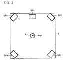
- FIG. 2 shows an arrangement example of the loudspeakers SP1 to SP5 in a listening room R of the audio system 1A.
- 5 loudspeakers SP1 to SP5 are arranged in the listening room R.
- the number of loudspeakers is not limited to 5, and may be 4 or less, or 6 or more.
- the number of the input audio signals may be 4 or less, or 6 or more.
- the audio system 1A may be a so-called 5.1 surround system including a subwoofer loudspeaker.
- a user A listens to the sound emitted from the loudspeakers SP1 to SP5 at a predetermined position (hereinafter, referred to as "reference position") Pref.
- the loudspeaker SP1 is arranged at the front of the user A.
- the loudspeaker SP2 is arranged diagonally right forward of the user A.
- the loudspeaker SP3 is arranged diagonally right rearward of the user A.
- the loudspeaker SP4 is arranged diagonally left rearward of the user A.
- the loudspeaker SP5 is arranged diagonally left forward of the user A.
- the user A simultaneously listens to the sounds emitted from the loudspeakers SP1 to SP5, thereby having a feeling that there is a sound source at a specific position.
- the audio device 20 generates the output audio signals OUT1 to OUT5 that sound as if the sound is coming from a desired position, based on the arrangement positions of the plurality of loudspeakers SP1 to SP5. The audio device 20 then outputs the generated output audio signals OUT1 to OUT5.
- the respective positions of the loudspeakers SP1 to SP5 are measured beforehand.
- FIG. 3 shows an example of a hardware configuration of the terminal device 10.
- the terminal device 10 includes a CPU 100, a memory 110, an operating unit 120, a display unit 130, a communication interface 140, a gyro sensor 151, an acceleration sensor 152, and an orientation sensor 153.
- the CPU 100 functions as a control center of the entire device.
- the memory 110 memorizes a program such as an application program, and functions as a work area of the CPU 100.
- the operating unit 120 receives an input of an instruction from a user.
- the display unit 130 displays operation details and the like.
- the communication interface 140 performs communication with outside.
- the X axis corresponds to a width direction of the terminal device 10.
- the Y axis corresponds to a height direction of the terminal device 10.
- the Z axis corresponds to a thickness direction of the terminal device 10.
- the X axis, the Y axis, and the Z axis are orthogonal to each other.
- a pitch angle (pitch), a roll angle (roll), and a yaw angle (yaw) are respectively rotation angles around the X axis, the Y axis, and the Z axis.
- the gyro sensor 151 detects and outputs the pitch angle, the roll angle, and the yaw angle of the terminal device 10.
- An orientation direction of the terminal device 10 can be specified based on these rotation angles.
- the acceleration sensor 152 measures an X-axis, a Y-axis, and a Z-axis direction component of acceleration added to the terminal device 10.
- acceleration measured by the acceleration sensor 152 is represented by three-dimensional vectors.
- the direction in which the terminal device 10 faces can be specified based on the three-dimensional vectors.
- the orientation sensor 153 detects, for example, geomagnetism to thereby measure the orientation in which the orientation sensor 153 faces.
- the direction in which the terminal device 10 faces can be specified based on this orientation.
- Signals output by the gyro sensor 151 and the acceleration sensor 152 are in a triaxial coordinate system provided in the terminal device 10, and are not in a coordinate system fixed to the listening room.
- the direction measured by the gyro sensor 151 and the acceleration sensor 152 is relative orientation. That is to say, when the gyro sensor 151 or the acceleration sensor 152 is used, an arbitrary target fixed in the listening room is used as a reference, and an angle with respect to the reference is acquired as a relative direction.
- the signal output by the orientation sensor 153 is the orientation on the earth, and indicates an absolute direction.
- the CPU 100 executes the application program to measure the direction in which the terminal device 10 faces by using at least one of outputs of the gyro sensor 151, the acceleration sensor 152, and the orientation sensor 153.
- the terminal device 10 includes the gyro sensor 151, the acceleration sensor 152, and the orientation sensor 153.
- the terminal device 10 may include only one of the gyro sensor 151, the acceleration sensor 152, and the orientation sensor 153.
- the gyro sensor 151 and the acceleration sensor 152 output angles. The angle is indicated by a value with respect to an arbitrary reference.
- a target to be the reference may be selected arbitrarily from objects in the listening room. As a specific example, a case where a loudspeaker whose direction is measured first, of the loudspeakers SP1 to SP5, is selected as the target will be described later.
- the orientation sensor 153 outputs a value indicating the absolute direction.
- the audio device 20 includes a CPU 210, a communication interface 220, a memory 230, an external interface 240, a reference signal generation circuit 250, a selection circuit 260, and m processing units U1 to Um.
- the CPU 210 functions as a control center of the entire device.
- the communication interface 220 executes communication with the outside.
- the memory 230 memorizes a program and data, or functions as a work area of the CPU 210.
- the external interface 240 receives an input of a signal from an external device such as a microphone, and supplies the signal to the CPU 210.
- the reference signal generation circuit 250 generates reference signals Sr1 to Sr5.
- the processing units U1 to Um and the CPU210 generate output audio signals OUT1 to OUT5, in which an audio effect is added to input audio signals IN1 to IN5, based on the respective positions of the loudspeakers SP1 to SP5.
- the output audio signals OUT1 to OUT5 are respectively supplied to the loudspeakers SP1 to SP5.
- the j-th processing unit Uj includes a virtual sound source generation unit (hereinafter, simply referred to as "conversion unit") 300, a frequency correction unit 310, a gain distribution unit 320, and adders 331 to 335 ("j" is an arbitrary natural number satisfying 1 ⁇ j ⁇ m).
- conversion unit virtual sound source generation unit
- frequency correction unit a frequency correction unit
- gain distribution unit a gain distribution unit
- adders 331 to 335 (“j" is an arbitrary natural number satisfying 1 ⁇ j ⁇ m).
- the processing units U1, U2, and so forth, Uj-1, Uj+1, and so forth, and Um are configured to be the same as the processing unit Uj.
- the conversion unit 300 generates an audio signal of a virtual sound source, based on the input audio signals IN1 to IN5.
- the conversion unit 300 includes 5 switches SW1 to SW5, and a mixer 301.
- the CPU 210 controls the conversion unit 300. More specifically, the CPU 210 memorizes a virtual sound source management table for managing m virtual sound sources in the memory 230, and controls the conversion unit 300, by referring to the virtual sound source management table. Reference data representing which input audio signals IN1 to IN5 need to be mixed for the respective virtual sound sources, is stored in the virtual sound source management table.
- the reference data may be, for example, a channel identifier indicating a channel to be mixed, or a logical value representing whether to perform mixing for each channel.
- the CPU 210 refers to the virtual sound source management table to sequentially turn on the switches corresponding to the input audio signal to be mixed, of the input audio signals IN1 to IN5, and fetches the input audio signals to be mixed.
- the input audio signals to be mixed are the input audio signals IN1, IN2, and IN5 is described here. In this case, the CPU 210 switches on the switch SW1 corresponding to the input audio signal IN1, and switches off the other switches SW2 to SW5.
- the CPU 210 switches on the switch SW2 corresponding to the input audio signal IN2, and switches off the other switches SW1, and SW3 to SW5. Then, the CPU 210 switches on the switch SW5 corresponding to the input audio signal IN5, and switches off the other switches SW1 to SW4.
- the frequency correction unit 310 performs frequency correction on an output signal of the conversion unit 300. Specifically, under control of the CPU 210, the frequency correction unit 310 corrects a frequency characteristic of the output signal according to a distance from the position of the virtual sound source to the reference position Pref. More specifically, the CPU 210 corrects the frequency characteristic of the output signal such that high-pass frequency components are largely attenuated, as the distance from the position of the virtual sound source to the reference position Pref increases. This is for reproducing acoustic characteristics such that an attenuation amount of the high frequency components increases, as the distance from the virtual sound source to the reference position Pref increases.
- the memory 230 memorizes an attenuation amount table beforehand.
- the attenuation amount table data representing a relation between the distance from the virtual sound source to the reference position Pref, and the attenuation amount of the respective frequency components is stored.
- the virtual sound source management table data representing the positions of the respective virtual sound sources is stored.
- the position of the virtual sound source is represented by, for example, three-dimensional orthogonal coordinates, two-dimensional orthogonal coordinates, or polar coordinates, with the reference position Pref as the origin.
- the CPU 210 executes first to third processes described below.
- the CPU 210 reads a content of the virtual sound source management table memorized in the memory 230. Further, the CPU 210 calculates the distance from the respective virtual sound sources to the reference position Pref, based on the read content of the virtual sound source management table.
- the CPU 210 refers to the attenuation amount table to acquire the attenuation amounts of the respective frequencies according to the calculated distance to the reference position Pref.
- the CPU 210 controls the frequency correction unit 310 so that the frequency characteristic corresponding to the acquired attenuation amount can be acquired.
- the gain distribution unit 320 distributes the output signal of the frequency correction unit 310 to a plurality of audio signals Aj[1] to Aj [5] for the loudspeakers SP1 to SP5. At this time, the gain distribution unit 320 amplifies the output signal of the frequency correction unit 310 at a predetermined ratio for each of the audio signals Aj[1] to Aj[5]. The size of the gain of the audio signal with respect to the output signal decreases, as the distances between the respective loudspeakers SP1 to SP5 and the virtual sound source increases. According to such a process, a sound field as if sound is emitted from a place set as the position of the virtual sound source can be formed.
- the size of the gain of the respective audio signals Aj[1] to Aj[5] may be proportional to a reciprocal of the distances between the respective loudspeakers SP1 to SP5 and the virtual sound source.
- the size of the gain may be set so as to be proportional to a reciprocal of the square or the fourth power of the distances between the respective loudspeakers SP1 to SP5 and the virtual sound source. If the distance between any of the loudspeakers SP1 to SP5 and the virtual sound source is substantially 0, the gain of the audio signals Aj[1] to Aj[5] with respect to the other loudspeakers SP1 to SP5 may be set to 0.
- the memory 230 memorizes, for example, a loudspeaker management table.
- a loudspeaker management table data indicating the respective positions of the loudspeakers SP1 to SP5 and data indicating the distances between the respective loudspeakers SP1 to SP5 and the reference position Pref are stored in a state of being associated with identifiers of the respective loudspeakers SP1 to SP5.
- the positions of the loudspeakers SP1 to SP5 are represented by, for example, three-dimensional orthogonal coordinates or polar coordinates, with the reference position Pref as the origin.
- the CPU 210 refers to the virtual sound source management table and the loudspeaker management table stored in the memory 230, and calculates the distances between the respective loudspeakers SP1 to SP5 and the respective virtual sound sources.
- the CPU 210 calculates the gain of the audio signals Aj[1] to Aj [5] with respect to the respective loudspeakers SP1 to SP5 based on the calculated distance, and supplies a control signal designating the gain to the respective processing units U1 to Um.
- the adders 331 to 335 of the processing unit Uj add the audio signals Aj[1] to Aj[5] output from the gain distribution unit 320 and audio signals Oj-1[1] to Oj-1[5] supplied from the processing unit Uj-1 in the previous stage, and output audio signals Oj[1] to Oj[5].
- the reference signal generation circuit 250 Under control of the CPU 210, the reference signal generation circuit 250 generates the reference signals Sr1 to Sr5 to be used for the measurement of the distances between the loudspeakers SP1 to SP5 and the reference position Pref (a microphone M), and outputs the reference signals to the selection circuit 260.
- the CPU 210 causes the reference signal generation circuit 250 to generate the reference signals Sr1 to Sr5.
- the CPU 210 controls the selection circuit 260 to select the reference signals Sr1 to Sr5, and supply them to the loudspeakers SP1 to SP5 respectively.
- the CPU 210 controls the selection circuit 260 to select the audio signals Om[1] to Om[5], and supply them to the loudspeakers SP1 to SP5 respectively.
- first to third processes are executed.
- the first process the distances between the respective loudspeakers SP1 to SP5 and the reference position Pref are measured.
- the second process the direction in which the respective loudspeakers SP1 to SP5 are arranged is measured.
- the third process the respective positions of the loudspeakers SP1 to SP5 are specified based on the measured distance and direction.
- FIG. 6 shows the microphone M in the measurement of the distance, as shown in FIG. 6 , the microphone M is arranged at the reference position Pref, and the microphone M is connected to the audio device 20.
- the output signal of the microphone M is supplied to the CPU 210 via the external interface 240.
- FIG. 7 shows the content of a measurement process for the distances between the loudspeakers SP1 to SP5 and the reference position Pref, to be executed by the CPU 210 of the audio device 20.
- the CPU 210 specifies one loudspeaker, for which measurement has not been finished, as the loudspeaker to be measured. For example, if measurement of the distance between the loudspeaker SP1 and the reference position Pref has not been performed, the CPU 210 specifies the loudspeaker SP1 as the loudspeaker to be measured.
- the CPU 210 controls the reference signal generation circuit 250 so as to generate the reference signal corresponding to the loudspeaker to be measured, of the reference signals Sr1 to Sr5. Moreover, the CPU 210 controls the selection circuit 260 so that the generated reference signal is supplied to the loudspeaker to be measured. At this time, the generated reference signal is output as one of the output audio signals OUT1 to OUT5 corresponding to the loudspeaker to be measured. For example, the CPU 210 controls the selection circuit 260 so that the generated reference signal Sr1 is output as the output audio signal OUT1 corresponding to the loudspeaker SP1 to be measured.
- the CPU 210 calculates the distance between the loudspeaker to be measured and the reference position Pref, based on the output signal of the microphone M. Moreover, the CPU 210 records the calculated distance in the loudspeaker management table, in association with the identifier of the loudspeaker to be measured.
- the CPU 210 determines whether measurement of all the loudspeakers is complete. If there is a loudspeaker whose measurement has not been finished (step S4: NO), the CPU 210 returns the process to step S1, and repeats the process from step S1 to step S4 until measurement of all the loudspeakers is complete. If measurement of all the loudspeakers is complete (step S4: YES), the CPU 210 finishes the process.
- the distances from the reference position Pref to loudspeakers SP1 to SP5 are measured.
- the distance from the reference position Pref to the loudspeaker SP1 is "L".
- the loudspeaker SP1 is on a circle having a radius L from the reference position Pref.
- the direction of the loudspeaker SP1 as seen from the reference position Pref is measured by using the terminal device 10 to specify the position of the loudspeaker SP1.
- FIG. 9 shows the content of a direction measurement process executed by the CPU 100 of the terminal device 10.
- the respective directions of loudspeakers SP1 to SP5 are specified by using at least one of the gyro sensor 151 and the acceleration sensor 152.
- the gyro sensor 151 and the acceleration sensor 152 output the angle.
- the reference of the angle is the loudspeaker whose arrangement direction is measured first.
- the CPU 100 Upon startup of the application of the direction measurement process, the CPU 100 causes the display unit 130 to display an image urging the user to perform a setup operation in a state with the terminal device 10 oriented toward the first loudspeaker. For example, if the arrangement direction of the loudspeaker SP1 is set first, as shown in FIG. 10 , the CPU 100 displays an arrow a1 oriented toward the loudspeaker SP1 on the display unit 130.
- the CPU 100 determines whether the setup operation has been performed by the user. Specifically, the CPU 100 determines whether the user has pressed a setup button B (a part of the above-described operating unit 120) shown in FIG. 10 . If the setup operation has not been performed, the CPU 100 repeats determination until the setup operation is performed.
- the CPU 100 sets the measurement angle measured by the gyro sensor 151 or the acceleration sensor 152 at the time of operation as the angle to be the reference. That is to say, the CPU 100 sets the direction from the reference position Pref toward the loudspeaker SP1 to 0 degree.
- the CPU 100 causes the display unit 130 to display an image urging the user to perform the setup operation in a state with the terminal device 10 oriented toward the next loudspeaker. For example, if the arrangement direction of the loudspeaker SP2 is set in the second place, as shown in FIG. 11 , the CPU 100 displays an arrow a2 oriented toward the loudspeaker SP2 on the display unit 130.
- the CPU 100 determines whether the setup operation has been performed by the user. Specifically, the CPU 100 determines whether the user has pressed the setup button shown in FIG. 11 . If the setup operation has not been performed, the CPU 100 repeats determination until the setup operation is performed.
- the CPU 100 uses the output value of the gyro sensor 151 or the acceleration sensor 152 at the time of operation to memorize the angle of the loudspeaker to be measured with respect to the reference, in the memory 110.
- the CPU 100 determines whether measurement is complete for all the loudspeakers. If there is a loudspeaker whose measurement has not been finished (step S26: NO), the CPU 100 returns the process to step S23, and repeats the process from step S23 to step S26 until measurement is complete for all the loudspeakers.
- the CPU 100 transmits a measurement result to the audio device 20 by using the communication interface 140.
- the directions in which the loudspeakers SP1 to SP5 are respectively arranged are measured.
- the measurement results are collectively transmitted to the audio device 20.
- the transmission method is not limited to such a process.
- the CPU 100 may transmit the measurement result to the audio device 20 every time the arrangement direction of one loudspeaker is measured.
- the arrangement direction of the loudspeaker SP1 to be measured first is used as the reference of the angle of the other loudspeakers SP2 to SP5.
- the angle relating to the loudspeaker SP1 is 0 degree. Therefore, transmission of the measurement result relating to the loudspeaker SP1 may be omitted.
- the load on the user can be reduced by setting the reference to one of the loudspeakers SP1 to SP5.
- the reference of the angle does not correspond to any of the loudspeakers SP1 to SP5, and the reference of the angle is an arbitrary target arranged in the listening room will be described here.
- the user orients the terminal device 10 to the target, and performs setup of the reference angle by performing a predetermined operation in this state. Further, the user performs a predetermined operation in a state with the terminal device 10 oriented toward each of the loudspeakers SP1 to SP5, thereby designating the direction.
- the reference of the angle is the arbitrary target arranged in the listening room, an operation to be performed in the state with the terminal device 10 oriented toward the target is required additionally.
- the target is set to any one of the loudspeakers SP1 to SP5, the input operation can be simplified.
- the CPU 210 of the audio device 20 acquires the (information indicating) arrangement direction of each of the loudspeakers SP1 to SP5 by using the communication interface 220.
- the CPU 210 calculates the respective positions of the loudspeakers SP1 to SP5 based on the arrangement direction and the distance of each of the loudspeakers SP1 to SP5. That is to say, the CPU 210 and the communication interface 220 function as an acquisition unit that acquires the arrangement directions of the respective loudspeakers SP1 to SP5.
- the CPU 210 calculates the coordinates (x3, y3) of the loudspeaker SP3 according to equation (A) shown below.
- x 3 , y 3 L 3 sin ⁇ , L 3 cos ⁇
- the CPU 210 calculates the respective positions of the loudspeakers SP1 to SP5 based on the distance from the reference position Pref to the respective loudspeakers SP1 to SP5, and the arrangement direction of the respective loudspeakers SP1 to SP5.
- designation process for the position of the virtual sound source is described.
- designation of the position of the virtual sound source is performed by using the terminal device 10.
- FIG. 13 shows the content of the designation process for the position of the virtual sound source executed by the CPU 100 of the terminal device 10.
- the CPU 100 causes the display unit 130 to display an image urging the user to select a channel to be a virtual sound source, and acquires the number of the channel selected by the user.
- the CPU 100 causes the display unit 130 to display the screen shown in FIG. 14 .
- the number of virtual sound sources is 5. Numbers of "1" to "5" are allocated to each of the virtual sound sources.
- the channel can be selected by a pull-down menu. In FIG. 14 , the channel corresponding to virtual sound source number 5 is displayed in the pull-down menu.
- the channel includes center, right front, left front, right surround, and left surround.
- the CPU 100 causes the display unit 130 to display an image urging the user to perform the setup operation in a state with the terminal device oriented toward the target. It is desired that the target agrees with the target used as the reference of the angle of the loudspeaker in the specification process for the position of the loudspeaker. Specifically, it is desired to set the target to the loudspeaker SP1 to be set first. In this case, the CPU 100 causes the display unit 130 to display the screen shown in FIG. 10 to urge the user to perform the setup operation.
- the CPU 100 determines whether the setup operation has been performed by the user. Specifically, the CPU 100 determines whether the user has pressed the setup button B shown in FIG. 10 . If the setup operation has not been performed, the CPU 100 repeats the determination until the setup operation is performed.
- the CPU 100 sets the measurement angle measured by the gyro sensor 151 and the like at the time of operation, as the angle to be the reference. That is to say, the CPU 100 sets the direction from the reference position Pref toward the loudspeaker SP1 (target) to 0 degree.
- the CPU 100 causes the display unit 130 to display an image urging the user to perform the setup operation in a state with the terminal device oriented toward the direction in which the user desires to arrange the virtual sound source. For example, the CPU 100 displays the screen shown in FIG. 15A on the display unit 130.
- the CPU 100 determines whether the user has performed the setup operation. Specifically, the CPU 100 determines whether the user has pressed the setup button B shown in FIG. 15A . If the setup operation has not been performed, the CPU 100 repeats the determination until the setup operation is performed.
- the angle of the virtual sound source with respect to the reference is memorized in the memory 110 by using an output value of the gyro sensor 151 or the like at the time of operation.
- the CPU 100 receives an input of the distance from the virtual sound source to the reference position Pref. For example, the CPU 100 causes the display unit 130 to display the screen shown in FIG. 15B to urge the user to input the distance to the virtual sound source. If the user inputs the distance in an input box F and presses the setup button B, the CPU 100 acquires the distance input as the distance from the reference position Pref to the virtual sound source.
- the CPU 100 transmits to the audio device 20, the (information indicating) arrangement direction of the virtual sound source and the distance to the virtual sound source, as a setup result.
- the CPU 210 of the audio device 20 receives the setup result by using the communication interface 220.
- the CPU 210 calculates the position of the virtual sound source by using the same method as that for calculating the absolute position of the loudspeaker based on the direction and the distance of the loudspeaker.
- the CPU 210 controls the processing units U1 to Um based on the position of the virtual sound source and the positions of the loudspeakers SP1 to SP5, so that sound is heard from the position of the virtual sound source.
- the output audio signals OUT1 to OUT5 obtained by performing sound processing such that the sound of the designated channel is heard from the position of the virtual sound source, are generated by using the terminal device 10.
- the arrangement direction of the virtual sound source and the distance to the virtual sound source are transmitted from the terminal device 10 to the audio device 20 as a designated position indicating the position of the virtual sound source.
- the terminal device 10 may calculate a coordinate of the designated position based on the arrangement position of the virtual sound source and the distance to the virtual sound source, and transmit the coordinate to the audio device 20.
- information in any format may be transmitted from the terminal device 10 to audio device 20, so long as the designated position can be specified.
- the reference of the angle of the loudspeakers SP1 to SP5 is matched with the reference of the angle of the virtual sound source.
- specification of the arrangement direction of the virtual sound source can be executed by the same process as that for specifying the arrangement directions of the respective loudspeakers SP1 to SP5. Consequently, because two processes can be commonalized, specification of the position of the loudspeaker and specification of the position of the virtual sound source can be performed by using the same program module.
- the user uses the common target (in the example, the loudspeaker SP1) as the reference of the angle, the individual target need not be memorized.
- the audio system 1A includes the terminal device 10 and the audio device 20.
- the terminal device 10 and the audio device 20 share various types of functions.
- FIG. 16 shows functions to be shared by the terminal device 10 and the audio device 20 in the audio system 1A.
- the terminal device 10 includes an input unit F11, a direction measurement unit F12, a first communication unit F 13, and a first control unit F14.
- the input unit F11 receives an input of an instruction from the user.
- the direction measurement unit F12 measures the arrangement directions of the respective loudspeakers SP1 to SP5.
- the first communication unit F13 communicates with the audio device 20.
- the input unit F11 corresponds to the operating unit 120 described above.
- the first communication unit F13 corresponds to the communication interface 140 described above.
- the direction measurement unit F12 corresponds to the gyro sensor 151, the acceleration sensor 152, the orientation sensor 153, and the CPU 100 described above.
- the first control unit F 14 corresponds to the CPU 100.
- the first control unit F 14 controls the direction measurement unit F 12 to measure the arrangement direction of the loudspeaker (the above-described step S25). Moreover, the first control unit F14 controls the first communication unit F13 to transmit the arrangement directions of the respective loudspeakers SP1 to SP5 measured by the direction measurement unit F12, to the audio device 20 (the above-described step S27).
- the audio device 20 includes a second communication unit F23, a calculation unit F21, a signal generation unit F22, a storage unit F25, and a second control unit F24.
- the second communication unit F23 communicates with the terminal device 10.
- the calculation unit F21 calculates the respective positions of the loudspeakers SP1 to SP5 based on the distance from the reference position Pref to the respective loudspeakers SP1 to SP5 and the arrangement directions of the respective loudspeakers SP1 to SP5.
- the signal generation unit F22 generates the output audio signals OUT1 to OUT5 generated by adding the acoustic effect to the input audio signals for the loudspeakers SP1 to SP5 based on the respective positions of the loudspeakers SP1 to SP5.
- the storage unit F25 memorizes the distances from the reference position Pref to the respective loudspeakers SP1 to SP5.
- the second control unit F24 supplies the received arrangement directions of the respective loudspeakers SP1 to SP5 to the calculation unit F21, and supplies the distances from the reference position Pref to the respective loudspeakers SP1 to SP5 read from the storage unit F25, to the calculation unit F21.
- the second communication unit F23 corresponds to the communication interface 220 described above.
- the calculation unit F21 and the second control unit F24 correspond to the CPU 210.
- the signal generation unit F22 corresponds to the CPU 210 and the processing units U1 to Um.
- the storage unit F25 corresponds to the memory 230.
- the distances from the reference position Pref to the respective loudspeakers SP1 to SP5 are measured beforehand.
- the arrangement directions of the respective loudspeakers SP1 to SP5 are measured by using the terminal device 10, and the measurement results are transmitted to the audio device 20.
- the calculation unit F21 of the audio device 20 can calculate the respective positions of the loudspeakers SP1 to SP5.
- the signal generation unit F22 generates the output audio signals OUT1 to OUT5 added with the acoustic effect, based on the calculated respective positions of the loudspeakers SP1 to SP5. Consequently, even if the loudspeakers SP1 to SP5 are not arranged at the ideal positions, an acoustic effect such as the arrangement and surround effect of the virtual sound source can be realized, considering the actual positions.
- the respective positions of the loudspeakers SP1 to SP5 are calculated by the calculation unit F21 provided in the audio device 20.
- the terminal device 10 may calculate the respective positions of the loudspeakers SP1 to SP5.
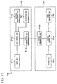
- FIG. 17 shows a configuration example of an audio system 1B according to a first modification example.
- the audio system 1B is configured in the same manner as the audio system 1A shown in FIG. 16 , except that the calculation unit F21 is deleted from the audio device 20, and the calculation unit F21 is provided in the terminal device 10.
- the second control unit F24 controls the second communication unit F23 so as to transmit the distance to each of the loudspeakers SP1 to SP5 read from the storage unit F25, to the terminal device 10. Moreover, the second control unit F24 supplies the respective positions of the loudspeakers SP1 to SP5 received by using the second communication unit F23, to the signal generation unit F22.
- the first control unit F14 controls the direction measurement unit F12 to measure the arrangement direction of the loudspeaker. Moreover, the first control unit F14 controls the calculation unit F21 to calculate the respective positions of the loudspeakers SP1 to SP5, based on the respective directions of the loudspeakers SP1 to SP5 measured by the direction measurement unit F12 and the respective distances of the loudspeakers SP1 to SP5 received by using the first communication unit F 13. Furthermore, the first control unit F 14 controls the first communication unit F13 so as to transmit the respective positions of the loudspeakers SP1 to SP5 calculated by the calculation unit F21, to the audio device 20.
- the terminal device 10 executes calculation of the respective positions of the loudspeakers SP1 to SP5.
- the processing load on the audio device 20 can be reduced.
- the audio device 20 can memorize the respective positions of the loudspeakers SP1 to SP5 received from the terminal device 10, and can use these positions to add the acoustic effect subsequently.
- the respective positions of the loudspeakers SP1 to SP5 are memorized in the storage unit F25 provided in the audio device 20.
- the terminal device 10 may include the storage unit F25.
- the terminal device 10 transmits the arrangement directions of the respective loudspeakers SP1 to SP5 measured by the direction measurement unit F12 and the distances of the respective loudspeakers SP1 to SP5 memorized in the storage unit F25, to the audio device 20.
- the calculation unit F21 of the audio device 20 calculates the respective positions of the loudspeakers SP1 to SP5 based on the arrangement directions of the respective loudspeakers SP1 to SP5 and the distances to the respective loudspeakers SP1 to SP5.
- the terminal device 10 may include the storage unit F25 and the calculation unit F21.
- the calculation unit F21 may transmit the calculated respective positions of the loudspeakers SP1 to SP5 to the audio device 20.
- the respective positions of the loudspeakers SP1 to SP5 may be memorized in the memory 230 of the audio device 20.
- the output audio signals OUT1 to OUT5 added with the acoustic effect may be generated based on the memorized respective positions of the loudspeakers SP1 to SP5.
- measurement of the arrangement directions of the respective loudspeakers SP1 to SP5 is performed at the reference position Pref, when the user A sets the listening position in the listening room to the reference position Pref.
- the arrangement directions of the loudspeakers SP1 to SP5 may be measured at an arbitrary position. In this case, the process described below is performed. That is to say, the terminal device 10 transmits a relative positional relation between the arbitrary position and the reference position to the audio device 20.
- the calculation unit F21 calculates the respective positions of the loudspeakers SP1 to SP5 based on the relative positional relation, the arrangement directions of the loudspeakers SP1 to SP5 as seen from the arbitrary position, and the distances between the respective loudspeakers SP1 to SP5 and the reference position Pref. More specifically, the calculation unit F21 converts the direction of the relative positional relation of the loudspeakers as seen from the arbitrary position into the directions of the loudspeakers SP1 to SP5 as seen from the reference position Pref, based on the relative positional relation. Moreover, the calculation unit F21 calculates the respective positions of the loudspeakers SP1 to SP5 based on the conversion result and the distances between the respective loudspeakers SP1 to SP5 and the reference position Pref.
- An arbitrary position P is set at a position shifted by ( ⁇ x, ⁇ y) from the reference position Pref.
- a distance from the reference position Pref to the loudspeaker SP1 is set as "L 1 ".
- a distance from the reference position Pref to the loudspeaker SP2 is set as "L 2 ".
- a distance from the reference position Pref to the predetermined position P is set as "L 3 ".
- a distance from the predetermined position P to the loudspeaker SP2 is set as "L 4 ".
- An angle of the loudspeaker SP2 with respect to the loudspeaker SP1 as a reference as seen from the reference position Pref is set as ⁇ .
- An angle of the loudspeaker SP2 with respect to the loudspeaker SP1 as the reference as seen from the predetermined position P is set as "0"'.
- Angles ⁇ b, ⁇ c, ⁇ d, and ⁇ e are set as shown in FIG. 18 .
- equation (6) is acquired.
- ⁇ d 90 ° - atan ⁇ y / ⁇ x - atan ⁇ x / L 1 + ⁇ y
- L 3 ⁇ x 2 + ⁇ y 2 1 / 2
- L 4 2 L 2 2 + L 3 3 + 2 L 2 L 3 cos ⁇ e
- " ⁇ x” and “ ⁇ y” are relative coordinates from the predetermined position P to the reference position Pref. Therefore, " ⁇ x” and “ ⁇ y” can be acquired by using an integration result of the output signal of the triaxial acceleration sensor 152 of the terminal device 10 and the output signal of the orientation sensor 153. Specifically, it is required that integration is started when the user inputs a start instruction by using the operating unit 120 at the arbitrary position P, and integration is finished when the user inputs an end instruction by using the operating unit 120 after the user has moved to the reference position Pref. Alternatively, the user may input " ⁇ x" and " ⁇ y” by using the operating unit 120.
- the direction measurement unit F12 sets the loudspeaker SP1 as the reference, and outputs the angle with respect to the reference, as the direction.
- the present invention is not limited to such a configuration.
- An arbitrary target arranged in the listening room may be set as the reference, and the angle with respect to the reference may be measured as the direction.
- the direction measurement unit F12 may set the television as a target and output the angle with respect to the television (target) as the reference, as the direction.
- the first control unit F 14 controls the direction measurement unit F12 so as to set the angle being the reference.
- the first control unit F14 controls the direction measurement unit F12 so as to measure the direction of that loudspeaker.
- the loudspeakers SP1 to SP5 may be arranged three-dimensionally.
- a loudspeaker SP6 is arranged diagonally upward forward left as seen from the reference position Pref.
- a loudspeaker SP6 is arranged diagonally upward forward right.
- the information indicating the arrangement directions of the loudspeakers measured by the terminal device is transmitted to the audio device. Consequently, when the distance to the loudspeaker is known, even if the position of the loudspeaker deviates from the ideal position, the audio device can calculate the actual positions of the plurality of loudspeakers, and can add the desired acoustic effect thereto. Moreover, in the measurement of the direction, the user only needs to operate the input unit by orienting the terminal device toward the target loudspeaker, thereby enabling to measure the arrangement direction of the loudspeaker easily.
- the distance to the loudspeaker is transmitted from the audio device to the terminal device.
- the terminal device calculates the position of the loudspeaker based on the measured arrangement direction of the loudspeaker and the received distance.
- the audio device need not include the calculation unit, and hence, the configuration of the audio device can be simplified.
- the target when the acceleration sensor and the gyro sensor that detect the relative direction are used as the direction measurement unit, the target can be set as the reference. Consequently, the angle formed by the arrangement direction of the target and the arrangement direction of the loudspeaker can be acquired.
- the designation direction in which the virtual sound source is positioned is input by using the terminal device
- the designation direction is input by using a target the same as the target which has been used as a reference in the measurement of the arrangement direction of the loudspeaker, as the reference.
- the angle of the virtual sound source with respect to the reference can be treated as the angle of the loudspeaker with respect to the reference.
- the arrangement process of the virtual sound source in the signal generation unit can be simplified.
- a relative angle error between the loudspeaker and the virtual sound source can be reduced by setting the same target as the reference.
- time and labor to input the reference can be simplified by setting a predetermined loudspeaker as the target.
- the order of designating the arrangement direction of the loudspeaker by the user by using the input unit may be preset.
- the target may be a loudspeaker to be designated first, of the plurality of loudspeakers.
- the information indicating the arrangement directions of the second loudspeaker and thereafter is provided as the angles with respect to the first loudspeaker as the reference.
- the predetermined loudspeaker may be a loudspeaker in an arbitrary order. In this case, it is appropriate to subtract the angle of the predetermined loudspeaker from the angle of other loudspeakers to specify the arrangement directions of the plurality of loudspeakers.
- the present invention is applicable to audio devices, audio systems, and methods.
Abstract
Description
- The present invention relates to a device that calculates a position of a loudspeaker.
- Priority is claimed on
Japanese Patent Application No. 2013-086875 filed on April 17, 2013 - An audio device that forms an audio field by a synthetic sound image by using a plurality of loudspeakers has been known. For example, there is an audio source in which multi-channel audio signals such as 5.1 channel signals are recorded, such as a DVD (Digital Versatile Disc). An audio device that reproduces such an audio source has been widely used even in general households. If each loudspeaker is arranged at a recommended position in a listening room, when the audio source is reproduced by using the audio device, a sound reproduction effect such as a surround effect can be acquired. On the other hand, if the arrangement of the loudspeakers is different from the recommended position, the localization of sound may be inadequate. A technique for forming a desired audio field by performing pickup of sound emitted from loudspeakers, by a microphone to calculate a position deviation of the loudspeakers and correcting the sound emitted from the loudspeakers based on the calculation result has been known (for example, refer to
- [Patent Document 1]
Japanese Unexamined Patent Application, First Publication No. 2000-354300 - However, in the conventional audio device, four microphones are required in order to specify a three-dimensional position of the loudspeaker. Even if a deviation in a height direction is ignored, in order to specify a two-dimensional position of the loudspeaker, three microphones are required. In either case, there is a problem in that the audio system becomes expensive.
- If one microphone is shifted to perform measurement four times or three times, the position of the loudspeaker can be specified by one microphone. However, in this case, time is required for the measurement. Moreover, in order to move the microphone accurately, a seat or the like is required.
- The present invention has been conceived in view of the above situation. An example of an object of the present invention is to specify the position of the loudspeaker with a simple configuration.
- An audio device according to an aspect of the present invention includes: an acquisition unit that acquires first information indicating an arrangement direction of a first loudspeaker, the first information being measured by a terminal device in a state with the terminal device oriented toward the first loudspeaker; and a calculation unit that calculates a position of the first loudspeaker, at least based on a distance from a reference position to the first loudspeaker, and the first information.
- According to the above audio device, the calculation unit calculates the arrangement position of the loudspeaker based on two elements, that is, distance and direction. Therefore, in the case where the distance from the reference position to the loudspeaker is known, the position of the loudspeaker can be specified by only acquiring the arrangement direction of the loudspeaker. Moreover, an audio effect can be added based on a specified position of the loudspeaker. The distance to the loudspeaker can be measured with a simple configuration. Accordingly, even if the loudspeaker is deviated from an ideal position, a desired audio effect can be added with a simple configuration.
- The information indicating the arrangement direction of the loudspeaker acquired by the acquisition unit may indicate an arrangement direction as seen from the reference position, being a reference of the distance, or may indicate an arrangement direction as seen from an arbitrary position. When the information indicates the arrangement direction as seen from an arbitrary position, the acquisition unit may acquire the arrangement direction of the loudspeaker as seen from the arbitrary position, and a relative position between the arbitrary position and the reference position. Moreover, the calculation unit may calculate the position of the loudspeaker, based on a relative position, the arrangement direction of the loudspeaker as seen from an arbitrary position and the distance between the loudspeaker and the reference position. More specifically, the calculation unit may convert the information indicating the arrangement direction of the loudspeaker as seen from an arbitrary position into information indicating the arrangement direction of the loudspeaker as seen from the reference position. Furthermore, the calculation unit may calculate the position of the loudspeaker based on a conversion result and the distance between the loudspeaker and the reference position.
- An audio system according to an aspect of the present invention includes: a direction measurement unit that measures first information indicating an arrangement direction of a first loudspeaker in a state with a terminal device oriented toward the first loudspeaker; and a calculation unit that calculates a position of the first loudspeaker, at least based on a distance from a reference position to the first loudspeaker, and the first information.
- The distance to the loudspeaker can be measured with a simple configuration. According to the above audio system, the calculation unit calculates a position of the loudspeaker based on two elements, that is, distance and direction. Therefore, even if the loudspeaker is deviated from an ideal position, a desired audio effect can be added with a simple configuration.
- A method for an audio system according to an aspect of the present invention includes: measuring first information indicating an arrangement direction of a first loudspeaker in a state with a terminal device oriented toward the first loudspeaker; and calculating a position of the first loudspeaker, at least based on a distance from a reference position to the first loudspeaker, and the first information.
-
-
FIG. 1 is a block diagram showing a configuration example of an audio system, according to an embodiment of the present invention. -
FIG. 2 is a plan view showing arrangement of loudspeakers in a listening room, in the present embodiment. -
FIG. 3 is a block diagram showing an example of a hardware configuration of a terminal device, according to the present embodiment. -
FIG. 4 is a diagram for explaining an angle measured by a gyro sensor, according to the present embodiment. -
FIG. 5 is a block diagram showing an example of a hardware configuration of an audio device, according to the present embodiment. -
FIG. 6 is a plan view showing an arrangement of a microphone at the time of measuring a distance to the loudspeaker, in the present embodiment. -
FIG. 7 is a flowchart showing the content of a measurement process of a distance between a plurality of loudspeakers and a reference position, in the present embodiment. -
FIG. 8 is a diagram for explaining a position of the loudspeaker determined by a measurement result of the distance, in the present embodiment. -
FIG. 9 is a flowchart showing processing details of a direction measurement process, in the present embodiment. -
FIG. 10 is a diagram for explaining an example of an image to be displayed on a display unit in the direction measurement process, in the present embodiment. -
FIG. 11 is a diagram for explaining an example of an image to be displayed on the display unit in the direction measurement process, in the present embodiment. -
FIG. 12 is a diagram for explaining an example of calculating a position of the loudspeaker, in the present embodiment. -
FIG. 13 is a flowchart showing the content of a designation process for a position of a virtual sound source, in the present embodiment. -
FIG. 14 is a diagram for explaining an example of an image to be displayed on the display unit in the designation process for the position of the virtual sound source, in the present embodiment. -
FIG. 15A is a diagram for explaining an example of an image to be displayed on the display unit in the designation process for the position of the virtual sound source, in the present embodiment. -
FIG. 15B is a diagram for explaining an example of an image to be displayed on the display unit in the designation process for the position of the virtual sound source, in the present embodiment. -
FIG. 16 is a functional block diagram showing a functional configuration of the audio system, according to the present embodiment. -
FIG. 17 is a functional block diagram showing a functional configuration of an audio system, according to a first modification example of the present embodiment. -
FIG. 18 is a diagram for explaining a method of converting an angle of the loudspeaker as seen from an arbitrary position into an angle as seen from the reference position, in a third modification example of the present embodiment. -
FIG. 19 is a perspective view showing an example in which loudspeakers are arranged three-dimensionally, in a fifth modification example of the present embodiment. - Hereunder, embodiments of the present invention will be described with reference to the drawings.
-
FIG. 1 shows a configuration example of an audio system 1A according to a first embodiment of the present invention. The audio system 1A includes aterminal device 10, anaudio device 20, and a plurality of loudspeakers SP1 to SP5. Theterminal device 10 may be a communication device, for example, a smartphone. Theterminal device 10 is communicable with theaudio device 20. Theterminal device 10 and theaudio device 20 can perform communication via a wireless or wired network. For example, theterminal device 10 and theaudio device 20 may communicate with each other via a wireless LAN (Local Area Network). Theterminal device 10 can download an application program from a predetermined website on the Internet. The application program includes a program to be used for measuring respective directions of the loudspeakers SP1 to SP5. - The
audio device 20 may be a so-called multichannel amplifier. Theaudio device 20 generates output audio signals OUT1 to OUT5 in which an audio effect is added to input audio signals IN1 to IN5, and supplies the output audio signals OUT1 to OUT5 to the loudspeakers SP1 to SP5. The loudspeakers SP1 to SP5 are connected to theaudio device 20 via a wired or wireless network. -
FIG. 2 shows an arrangement example of the loudspeakers SP1 to SP5 in a listening room R of the audio system 1A. In the example, 5 loudspeakers SP1 to SP5 are arranged in the listening room R. However, the number of loudspeakers is not limited to 5, and may be 4 or less, or 6 or more. Similarly, the number of the input audio signals may be 4 or less, or 6 or more. For example, the audio system 1A may be a so-called 5.1 surround system including a subwoofer loudspeaker. - A user A listens to the sound emitted from the loudspeakers SP1 to SP5 at a predetermined position (hereinafter, referred to as "reference position") Pref. In the example, the loudspeaker SP1 is arranged at the front of the user A. The loudspeaker SP2 is arranged diagonally right forward of the user A. The loudspeaker SP3 is arranged diagonally right rearward of the user A. The loudspeaker SP4 is arranged diagonally left rearward of the user A. The loudspeaker SP5 is arranged diagonally left forward of the user A. The user A simultaneously listens to the sounds emitted from the loudspeakers SP1 to SP5, thereby having a feeling that there is a sound source at a specific position.
- The
audio device 20 generates the output audio signals OUT1 to OUT5 that sound as if the sound is coming from a desired position, based on the arrangement positions of the plurality of loudspeakers SP1 to SP5. Theaudio device 20 then outputs the generated output audio signals OUT1 to OUT5. The respective positions of the loudspeakers SP1 to SP5 are measured beforehand. -
FIG. 3 shows an example of a hardware configuration of theterminal device 10. In the example shown inFIG. 3 , theterminal device 10 includes aCPU 100, amemory 110, anoperating unit 120, adisplay unit 130, acommunication interface 140, agyro sensor 151, anacceleration sensor 152, and anorientation sensor 153. TheCPU 100 functions as a control center of the entire device. Thememory 110 memorizes a program such as an application program, and functions as a work area of theCPU 100. Theoperating unit 120 receives an input of an instruction from a user. Thedisplay unit 130 displays operation details and the like. Thecommunication interface 140 performs communication with outside. - In the example shown in
FIG. 4 , the X axis corresponds to a width direction of theterminal device 10. The Y axis corresponds to a height direction of theterminal device 10. The Z axis corresponds to a thickness direction of theterminal device 10. The X axis, the Y axis, and the Z axis are orthogonal to each other. A pitch angle (pitch), a roll angle (roll), and a yaw angle (yaw) are respectively rotation angles around the X axis, the Y axis, and the Z axis. Thegyro sensor 151 detects and outputs the pitch angle, the roll angle, and the yaw angle of theterminal device 10. An orientation direction of theterminal device 10 can be specified based on these rotation angles. Theacceleration sensor 152 measures an X-axis, a Y-axis, and a Z-axis direction component of acceleration added to theterminal device 10. In this case, acceleration measured by theacceleration sensor 152 is represented by three-dimensional vectors. The direction in which theterminal device 10 faces can be specified based on the three-dimensional vectors. Theorientation sensor 153 detects, for example, geomagnetism to thereby measure the orientation in which theorientation sensor 153 faces. The direction in which theterminal device 10 faces can be specified based on this orientation. Signals output by thegyro sensor 151 and theacceleration sensor 152 are in a triaxial coordinate system provided in theterminal device 10, and are not in a coordinate system fixed to the listening room. As a result, the direction measured by thegyro sensor 151 and theacceleration sensor 152 is relative orientation. That is to say, when thegyro sensor 151 or theacceleration sensor 152 is used, an arbitrary target fixed in the listening room is used as a reference, and an angle with respect to the reference is acquired as a relative direction. On the other hand, the signal output by theorientation sensor 153 is the orientation on the earth, and indicates an absolute direction. - The
CPU 100 executes the application program to measure the direction in which theterminal device 10 faces by using at least one of outputs of thegyro sensor 151, theacceleration sensor 152, and theorientation sensor 153. In the example shown inFIG. 3 , theterminal device 10 includes thegyro sensor 151, theacceleration sensor 152, and theorientation sensor 153. However, it is not limited to such a configuration. Theterminal device 10 may include only one of thegyro sensor 151, theacceleration sensor 152, and theorientation sensor 153. Thegyro sensor 151 and theacceleration sensor 152 output angles. The angle is indicated by a value with respect to an arbitrary reference. A target to be the reference may be selected arbitrarily from objects in the listening room. As a specific example, a case where a loudspeaker whose direction is measured first, of the loudspeakers SP1 to SP5, is selected as the target will be described later. - On the other hand, in the case where the directions of the loudspeakers SP1 to SP5 are measured by using the
orientation sensor 153, an input of the reference direction is not required. The reason for this is that theorientation sensor 153 outputs a value indicating the absolute direction. - In the example shown in
FIG. 5 , theaudio device 20 includes aCPU 210, acommunication interface 220, amemory 230, anexternal interface 240, a referencesignal generation circuit 250, aselection circuit 260, and m processing units U1 to Um. TheCPU 210 functions as a control center of the entire device. Thecommunication interface 220 executes communication with the outside. Thememory 230 memorizes a program and data, or functions as a work area of theCPU 210. Theexternal interface 240 receives an input of a signal from an external device such as a microphone, and supplies the signal to theCPU 210. The referencesignal generation circuit 250 generates reference signals Sr1 to Sr5. The processing units U1 to Um and the CPU210 generate output audio signals OUT1 to OUT5, in which an audio effect is added to input audio signals IN1 to IN5, based on the respective positions of the loudspeakers SP1 to SP5. The output audio signals OUT1 to OUT5 are respectively supplied to the loudspeakers SP1 to SP5. - The j-th processing unit Uj includes a virtual sound source generation unit (hereinafter, simply referred to as "conversion unit") 300, a
frequency correction unit 310, again distribution unit 320, andadders 331 to 335 ("j" is an arbitrary natural number satisfying 1≤j≤m). The processing units U1, U2, and so forth, Uj-1, Uj+1, and so forth, and Um are configured to be the same as the processing unit Uj. - The
conversion unit 300 generates an audio signal of a virtual sound source, based on the input audio signals IN1 to IN5. In the example, because m processing units U1 to Um are provided, the output audio signals OUT1 to OUT5 corresponding to m virtual sound sources can be generated. Theconversion unit 300 includes 5 switches SW1 to SW5, and amixer 301. TheCPU 210 controls theconversion unit 300. More specifically, theCPU 210 memorizes a virtual sound source management table for managing m virtual sound sources in thememory 230, and controls theconversion unit 300, by referring to the virtual sound source management table. Reference data representing which input audio signals IN1 to IN5 need to be mixed for the respective virtual sound sources, is stored in the virtual sound source management table. The reference data may be, for example, a channel identifier indicating a channel to be mixed, or a logical value representing whether to perform mixing for each channel. TheCPU 210 refers to the virtual sound source management table to sequentially turn on the switches corresponding to the input audio signal to be mixed, of the input audio signals IN1 to IN5, and fetches the input audio signals to be mixed. As a specific example, a case where the input audio signals to be mixed are the input audio signals IN1, IN2, and IN5 is described here. In this case, theCPU 210 switches on the switch SW1 corresponding to the input audio signal IN1, and switches off the other switches SW2 to SW5. Next, theCPU 210 switches on the switch SW2 corresponding to the input audio signal IN2, and switches off the other switches SW1, and SW3 to SW5. Then, theCPU 210 switches on the switch SW5 corresponding to the input audio signal IN5, and switches off the other switches SW1 to SW4. - The
frequency correction unit 310 performs frequency correction on an output signal of theconversion unit 300. Specifically, under control of theCPU 210, thefrequency correction unit 310 corrects a frequency characteristic of the output signal according to a distance from the position of the virtual sound source to the reference position Pref. More specifically, theCPU 210 corrects the frequency characteristic of the output signal such that high-pass frequency components are largely attenuated, as the distance from the position of the virtual sound source to the reference position Pref increases. This is for reproducing acoustic characteristics such that an attenuation amount of the high frequency components increases, as the distance from the virtual sound source to the reference position Pref increases. - The
memory 230 memorizes an attenuation amount table beforehand. In the attenuation amount table, data representing a relation between the distance from the virtual sound source to the reference position Pref, and the attenuation amount of the respective frequency components is stored. In the virtual sound source management table, data representing the positions of the respective virtual sound sources is stored. The position of the virtual sound source is represented by, for example, three-dimensional orthogonal coordinates, two-dimensional orthogonal coordinates, or polar coordinates, with the reference position Pref as the origin. - The
CPU 210 executes first to third processes described below. As a first process, theCPU 210 reads a content of the virtual sound source management table memorized in thememory 230. Further, theCPU 210 calculates the distance from the respective virtual sound sources to the reference position Pref, based on the read content of the virtual sound source management table. As a second process, theCPU 210 refers to the attenuation amount table to acquire the attenuation amounts of the respective frequencies according to the calculated distance to the reference position Pref. As a third process, theCPU 210 controls thefrequency correction unit 310 so that the frequency characteristic corresponding to the acquired attenuation amount can be acquired. - Under control of the
CPU 210, thegain distribution unit 320 distributes the output signal of thefrequency correction unit 310 to a plurality of audio signals Aj[1] to Aj [5] for the loudspeakers SP1 to SP5. At this time, thegain distribution unit 320 amplifies the output signal of thefrequency correction unit 310 at a predetermined ratio for each of the audio signals Aj[1] to Aj[5]. The size of the gain of the audio signal with respect to the output signal decreases, as the distances between the respective loudspeakers SP1 to SP5 and the virtual sound source increases. According to such a process, a sound field as if sound is emitted from a place set as the position of the virtual sound source can be formed. For example, the size of the gain of the respective audio signals Aj[1] to Aj[5] may be proportional to a reciprocal of the distances between the respective loudspeakers SP1 to SP5 and the virtual sound source. As another method, the size of the gain may be set so as to be proportional to a reciprocal of the square or the fourth power of the distances between the respective loudspeakers SP1 to SP5 and the virtual sound source. If the distance between any of the loudspeakers SP1 to SP5 and the virtual sound source is substantially 0, the gain of the audio signals Aj[1] to Aj[5] with respect to the other loudspeakers SP1 to SP5 may be set to 0. - The
memory 230 memorizes, for example, a loudspeaker management table. In the loudspeaker management table, data indicating the respective positions of the loudspeakers SP1 to SP5 and data indicating the distances between the respective loudspeakers SP1 to SP5 and the reference position Pref are stored in a state of being associated with identifiers of the respective loudspeakers SP1 to SP5. The positions of the loudspeakers SP1 to SP5 are represented by, for example, three-dimensional orthogonal coordinates or polar coordinates, with the reference position Pref as the origin. - As the first process, the
CPU 210 refers to the virtual sound source management table and the loudspeaker management table stored in thememory 230, and calculates the distances between the respective loudspeakers SP1 to SP5 and the respective virtual sound sources. As the second process, theCPU 210 calculates the gain of the audio signals Aj[1] to Aj [5] with respect to the respective loudspeakers SP1 to SP5 based on the calculated distance, and supplies a control signal designating the gain to the respective processing units U1 to Um. - The
adders 331 to 335 of the processing unit Uj add the audio signals Aj[1] to Aj[5] output from thegain distribution unit 320 and audio signals Oj-1[1] to Oj-1[5] supplied from the processing unit Uj-1 in the previous stage, and output audio signals Oj[1] to Oj[5]. As a result, an audio signal Om[k] output from the processing unit Um becomes Om[k]=A1[k]+A2[k]+···+Aj[k]+···+Am[k] ("k" is an arbitrary natural number from 1 to 5). - Under control of the
CPU 210, the referencesignal generation circuit 250 generates the reference signals Sr1 to Sr5 to be used for the measurement of the distances between the loudspeakers SP1 to SP5 and the reference position Pref (a microphone M), and outputs the reference signals to theselection circuit 260. At the time of measurement of the distances between loudspeakers SP1 to SP5 and the position Pref, theCPU 210 causes the referencesignal generation circuit 250 to generate the reference signals Sr1 to Sr5. When the distances to the plurality of loudspeakers SP1 to SP5 are to be measured respectively, theCPU 210 controls theselection circuit 260 to select the reference signals Sr1 to Sr5, and supply them to the loudspeakers SP1 to SP5 respectively. At the time of adding the audio effect, theCPU 210 controls theselection circuit 260 to select the audio signals Om[1] to Om[5], and supply them to the loudspeakers SP1 to SP5 respectively. - Next, an operation of the audio system will be described by dividing the operation into specification of the position of the loudspeaker and designation of the position of the virtual sound source.
- At the time of specifying the position of the loudspeaker, first to third processes are executed. As the first process, the distances between the respective loudspeakers SP1 to SP5 and the reference position Pref are measured. As the second process, the direction in which the respective loudspeakers SP1 to SP5 are arranged is measured. As the third process, the respective positions of the loudspeakers SP1 to SP5 are specified based on the measured distance and direction.
- In the measurement of the distance, as shown in
FIG. 6 , the microphone M is arranged at the reference position Pref, and the microphone M is connected to theaudio device 20. The output signal of the microphone M is supplied to theCPU 210 via theexternal interface 240.FIG. 7 shows the content of a measurement process for the distances between the loudspeakers SP1 to SP5 and the reference position Pref, to be executed by theCPU 210 of theaudio device 20. - The
CPU 210 specifies one loudspeaker, for which measurement has not been finished, as the loudspeaker to be measured. For example, if measurement of the distance between the loudspeaker SP1 and the reference position Pref has not been performed, theCPU 210 specifies the loudspeaker SP1 as the loudspeaker to be measured. - The
CPU 210 controls the referencesignal generation circuit 250 so as to generate the reference signal corresponding to the loudspeaker to be measured, of the reference signals Sr1 to Sr5. Moreover, theCPU 210 controls theselection circuit 260 so that the generated reference signal is supplied to the loudspeaker to be measured. At this time, the generated reference signal is output as one of the output audio signals OUT1 to OUT5 corresponding to the loudspeaker to be measured. For example, theCPU 210 controls theselection circuit 260 so that the generated reference signal Sr1 is output as the output audio signal OUT1 corresponding to the loudspeaker SP1 to be measured. - The
CPU 210 calculates the distance between the loudspeaker to be measured and the reference position Pref, based on the output signal of the microphone M. Moreover, theCPU 210 records the calculated distance in the loudspeaker management table, in association with the identifier of the loudspeaker to be measured. - The
CPU 210 determines whether measurement of all the loudspeakers is complete. If there is a loudspeaker whose measurement has not been finished (step S4: NO), theCPU 210 returns the process to step S1, and repeats the process from step S1 to step S4 until measurement of all the loudspeakers is complete. If measurement of all the loudspeakers is complete (step S4: YES), theCPU 210 finishes the process. - According to the above process, the distances from the reference position Pref to loudspeakers SP1 to SP5 are measured.
- For example, it is assumed that the distance from the reference position Pref to the loudspeaker SP1 is "L". In this case, as shown in
FIG. 8 , it is seen that the loudspeaker SP1 is on a circle having a radius L from the reference position Pref. However, it is not specified at which position on the circle the loudspeaker SP1 is. Therefore, in the present embodiment the direction of the loudspeaker SP1 as seen from the reference position Pref is measured by using theterminal device 10 to specify the position of the loudspeaker SP1. -
FIG. 9 shows the content of a direction measurement process executed by theCPU 100 of theterminal device 10. In the example, the respective directions of loudspeakers SP1 to SP5 are specified by using at least one of thegyro sensor 151 and theacceleration sensor 152. As described above, thegyro sensor 151 and theacceleration sensor 152 output the angle. In the example, the reference of the angle is the loudspeaker whose arrangement direction is measured first. - Upon startup of the application of the direction measurement process, the
CPU 100 causes thedisplay unit 130 to display an image urging the user to perform a setup operation in a state with theterminal device 10 oriented toward the first loudspeaker. For example, if the arrangement direction of the loudspeaker SP1 is set first, as shown inFIG. 10 , theCPU 100 displays an arrow a1 oriented toward the loudspeaker SP1 on thedisplay unit 130. - The
CPU 100 determines whether the setup operation has been performed by the user. Specifically, theCPU 100 determines whether the user has pressed a setup button B (a part of the above-described operating unit 120) shown inFIG. 10 . If the setup operation has not been performed, theCPU 100 repeats determination until the setup operation is performed. - If the setup operation is performed, the
CPU 100 sets the measurement angle measured by thegyro sensor 151 or theacceleration sensor 152 at the time of operation as the angle to be the reference. That is to say, theCPU 100 sets the direction from the reference position Pref toward the loudspeaker SP1 to 0 degree. - The
CPU 100 causes thedisplay unit 130 to display an image urging the user to perform the setup operation in a state with theterminal device 10 oriented toward the next loudspeaker. For example, if the arrangement direction of the loudspeaker SP2 is set in the second place, as shown inFIG. 11 , theCPU 100 displays an arrow a2 oriented toward the loudspeaker SP2 on thedisplay unit 130. - The
CPU 100 determines whether the setup operation has been performed by the user. Specifically, theCPU 100 determines whether the user has pressed the setup button shown inFIG. 11 . If the setup operation has not been performed, theCPU 100 repeats determination until the setup operation is performed. - If the setup operation is performed, the
CPU 100 uses the output value of thegyro sensor 151 or theacceleration sensor 152 at the time of operation to memorize the angle of the loudspeaker to be measured with respect to the reference, in thememory 110. - The
CPU 100 determines whether measurement is complete for all the loudspeakers. If there is a loudspeaker whose measurement has not been finished (step S26: NO), theCPU 100 returns the process to step S23, and repeats the process from step S23 to step S26 until measurement is complete for all the loudspeakers. - If measurement of the direction is complete for all the loudspeakers, the
CPU 100 transmits a measurement result to theaudio device 20 by using thecommunication interface 140. - According to the above process, the directions in which the loudspeakers SP1 to SP5 are respectively arranged are measured. In the above-described example, the measurement results are collectively transmitted to the
audio device 20. However, the transmission method is not limited to such a process. TheCPU 100 may transmit the measurement result to theaudio device 20 every time the arrangement direction of one loudspeaker is measured. As described above, the arrangement direction of the loudspeaker SP1 to be measured first is used as the reference of the angle of the other loudspeakers SP2 to SP5. The angle relating to the loudspeaker SP1 is 0 degree. Therefore, transmission of the measurement result relating to the loudspeaker SP1 may be omitted. - Thus, in the case where the respective arrangement directions of the loudspeakers SP1 to SP5 are specified by using the angle with respect to the reference, the load on the user can be reduced by setting the reference to one of the loudspeakers SP1 to SP5.
- A case where the reference of the angle does not correspond to any of the loudspeakers SP1 to SP5, and the reference of the angle is an arbitrary target arranged in the listening room will be described here. In this case, the user orients the
terminal device 10 to the target, and performs setup of the reference angle by performing a predetermined operation in this state. Further, the user performs a predetermined operation in a state with theterminal device 10 oriented toward each of the loudspeakers SP1 to SP5, thereby designating the direction. - Accordingly, if the reference of the angle is the arbitrary target arranged in the listening room, an operation to be performed in the state with the
terminal device 10 oriented toward the target is required additionally. On the other hand, by setting the target to any one of the loudspeakers SP1 to SP5, the input operation can be simplified. - The
CPU 210 of theaudio device 20 acquires the (information indicating) arrangement direction of each of the loudspeakers SP1 to SP5 by using thecommunication interface 220. TheCPU 210 calculates the respective positions of the loudspeakers SP1 to SP5 based on the arrangement direction and the distance of each of the loudspeakers SP1 to SP5. That is to say, theCPU 210 and thecommunication interface 220 function as an acquisition unit that acquires the arrangement directions of the respective loudspeakers SP1 to SP5. - As a specific example, as shown in
FIG. 12 , a case where the arrangement direction of the loudspeaker SP3 is an angle θ, and the distance to the loudspeaker SP3 is L3 will be described. In this case, theCPU 210 calculates the coordinates (x3, y3) of the loudspeaker SP3 according to equation (A) shown below.
- It also calculates the coordinates (x, y) for the other loudspeakers SP1, SP2, SP4, and SP5 in a similar manner.
- The
CPU 210 calculates the respective positions of the loudspeakers SP1 to SP5 based on the distance from the reference position Pref to the respective loudspeakers SP1 to SP5, and the arrangement direction of the respective loudspeakers SP1 to SP5. - Next, the designation process for the position of the virtual sound source is described. In the present embodiment, designation of the position of the virtual sound source is performed by using the
terminal device 10. -
FIG. 13 shows the content of the designation process for the position of the virtual sound source executed by theCPU 100 of theterminal device 10. - The
CPU 100 causes thedisplay unit 130 to display an image urging the user to select a channel to be a virtual sound source, and acquires the number of the channel selected by the user. For example, theCPU 100 causes thedisplay unit 130 to display the screen shown inFIG. 14 . In the example, the number of virtual sound sources is 5. Numbers of "1" to "5" are allocated to each of the virtual sound sources. The channel can be selected by a pull-down menu. InFIG. 14 , the channel corresponding to virtualsound source number 5 is displayed in the pull-down menu. The channel includes center, right front, left front, right surround, and left surround. When the user selects an arbitrary channel from the pull-down menu, theCPU 100 acquires the selected channel. - The
CPU 100 causes thedisplay unit 130 to display an image urging the user to perform the setup operation in a state with the terminal device oriented toward the target. It is desired that the target agrees with the target used as the reference of the angle of the loudspeaker in the specification process for the position of the loudspeaker. Specifically, it is desired to set the target to the loudspeaker SP1 to be set first. In this case, theCPU 100 causes thedisplay unit 130 to display the screen shown inFIG. 10 to urge the user to perform the setup operation. - The
CPU 100 determines whether the setup operation has been performed by the user. Specifically, theCPU 100 determines whether the user has pressed the setup button B shown inFIG. 10 . If the setup operation has not been performed, theCPU 100 repeats the determination until the setup operation is performed. - If the setup operation is performed, the
CPU 100 sets the measurement angle measured by thegyro sensor 151 and the like at the time of operation, as the angle to be the reference. That is to say, theCPU 100 sets the direction from the reference position Pref toward the loudspeaker SP1 (target) to 0 degree. - The
CPU 100 causes thedisplay unit 130 to display an image urging the user to perform the setup operation in a state with the terminal device oriented toward the direction in which the user desires to arrange the virtual sound source. For example, theCPU 100 displays the screen shown inFIG. 15A on thedisplay unit 130. - The
CPU 100 determines whether the user has performed the setup operation. Specifically, theCPU 100 determines whether the user has pressed the setup button B shown inFIG. 15A . If the setup operation has not been performed, theCPU 100 repeats the determination until the setup operation is performed. - If the setup operation is performed, the angle of the virtual sound source with respect to the reference is memorized in the
memory 110 by using an output value of thegyro sensor 151 or the like at the time of operation. - The
CPU 100 receives an input of the distance from the virtual sound source to the reference position Pref. For example, theCPU 100 causes thedisplay unit 130 to display the screen shown inFIG. 15B to urge the user to input the distance to the virtual sound source. If the user inputs the distance in an input box F and presses the setup button B, theCPU 100 acquires the distance input as the distance from the reference position Pref to the virtual sound source. - The
CPU 100 transmits to theaudio device 20, the (information indicating) arrangement direction of the virtual sound source and the distance to the virtual sound source, as a setup result. - The
CPU 210 of theaudio device 20 receives the setup result by using thecommunication interface 220. TheCPU 210 calculates the position of the virtual sound source by using the same method as that for calculating the absolute position of the loudspeaker based on the direction and the distance of the loudspeaker. TheCPU 210 controls the processing units U1 to Um based on the position of the virtual sound source and the positions of the loudspeakers SP1 to SP5, so that sound is heard from the position of the virtual sound source. As a result, the output audio signals OUT1 to OUT5 obtained by performing sound processing such that the sound of the designated channel is heard from the position of the virtual sound source, are generated by using theterminal device 10. In the example, the arrangement direction of the virtual sound source and the distance to the virtual sound source, are transmitted from theterminal device 10 to theaudio device 20 as a designated position indicating the position of the virtual sound source. However, the process is not limited to such a process. Theterminal device 10 may calculate a coordinate of the designated position based on the arrangement position of the virtual sound source and the distance to the virtual sound source, and transmit the coordinate to theaudio device 20. In other words, information in any format may be transmitted from theterminal device 10 toaudio device 20, so long as the designated position can be specified. - According to the above-described processes, the reference of the angle of the loudspeakers SP1 to SP5 is matched with the reference of the angle of the virtual sound source. As a result, specification of the arrangement direction of the virtual sound source can be executed by the same process as that for specifying the arrangement directions of the respective loudspeakers SP1 to SP5. Consequently, because two processes can be commonalized, specification of the position of the loudspeaker and specification of the position of the virtual sound source can be performed by using the same program module. Moreover, because the user uses the common target (in the example, the loudspeaker SP1) as the reference of the angle, the individual target need not be memorized.
- As described above, the audio system 1A includes the
terminal device 10 and theaudio device 20. Theterminal device 10 and theaudio device 20 share various types of functions.FIG. 16 shows functions to be shared by theterminal device 10 and theaudio device 20 in the audio system 1A. - The
terminal device 10 includes an input unit F11, a direction measurement unit F12, a first communication unit F 13, and a first control unit F14. The input unit F11 receives an input of an instruction from the user. The direction measurement unit F12 measures the arrangement directions of the respective loudspeakers SP1 to SP5. The first communication unit F13 communicates with theaudio device 20. The input unit F11 corresponds to theoperating unit 120 described above. The first communication unit F13 corresponds to thecommunication interface 140 described above. The direction measurement unit F12 corresponds to thegyro sensor 151, theacceleration sensor 152, theorientation sensor 153, and theCPU 100 described above. The first control unit F 14 corresponds to theCPU 100. When the user inputs that theterminal device 10 is oriented toward one of the loudspeakers SP1 to SP5 by using the input unit F11, the first control unit F 14 controls the direction measurement unit F 12 to measure the arrangement direction of the loudspeaker (the above-described step S25). Moreover, the first control unit F14 controls the first communication unit F13 to transmit the arrangement directions of the respective loudspeakers SP1 to SP5 measured by the direction measurement unit F12, to the audio device 20 (the above-described step S27). - The
audio device 20 includes a second communication unit F23, a calculation unit F21, a signal generation unit F22, a storage unit F25, and a second control unit F24. The second communication unit F23 communicates with theterminal device 10. The calculation unit F21 calculates the respective positions of the loudspeakers SP1 to SP5 based on the distance from the reference position Pref to the respective loudspeakers SP1 to SP5 and the arrangement directions of the respective loudspeakers SP1 to SP5. The signal generation unit F22 generates the output audio signals OUT1 to OUT5 generated by adding the acoustic effect to the input audio signals for the loudspeakers SP1 to SP5 based on the respective positions of the loudspeakers SP1 to SP5. The storage unit F25 memorizes the distances from the reference position Pref to the respective loudspeakers SP1 to SP5. When the second communication unit F23 receives the arrangement directions of the respective loudspeakers SP1 to SP5, the second control unit F24 supplies the received arrangement directions of the respective loudspeakers SP1 to SP5 to the calculation unit F21, and supplies the distances from the reference position Pref to the respective loudspeakers SP1 to SP5 read from the storage unit F25, to the calculation unit F21. - The second communication unit F23 corresponds to the
communication interface 220 described above. The calculation unit F21 and the second control unit F24 correspond to theCPU 210. The signal generation unit F22 corresponds to theCPU 210 and the processing units U1 to Um. The storage unit F25 corresponds to thememory 230. - As described above, according to the present embodiment, the distances from the reference position Pref to the respective loudspeakers SP1 to SP5 are measured beforehand. The arrangement directions of the respective loudspeakers SP1 to SP5 are measured by using the
terminal device 10, and the measurement results are transmitted to theaudio device 20. By performing the above process, the calculation unit F21 of theaudio device 20 can calculate the respective positions of the loudspeakers SP1 to SP5. Then the signal generation unit F22 generates the output audio signals OUT1 to OUT5 added with the acoustic effect, based on the calculated respective positions of the loudspeakers SP1 to SP5. Consequently, even if the loudspeakers SP1 to SP5 are not arranged at the ideal positions, an acoustic effect such as the arrangement and surround effect of the virtual sound source can be realized, considering the actual positions. - The present invention is not limited to the embodiment described above. Modification examples of the embodiment described above will be described below. The respective modification examples and the embodiment described above can be appropriately combined.
- In the embodiment described above, the respective positions of the loudspeakers SP1 to SP5 are calculated by the calculation unit F21 provided in the
audio device 20. However, the present invention is not limited to such a configuration. Theterminal device 10 may calculate the respective positions of the loudspeakers SP1 to SP5. -
FIG. 17 shows a configuration example of an audio system 1B according to a first modification example. The audio system 1B is configured in the same manner as the audio system 1A shown inFIG. 16 , except that the calculation unit F21 is deleted from theaudio device 20, and the calculation unit F21 is provided in theterminal device 10. - In the
audio device 20 of the audio system 1B, the second control unit F24 controls the second communication unit F23 so as to transmit the distance to each of the loudspeakers SP1 to SP5 read from the storage unit F25, to theterminal device 10. Moreover, the second control unit F24 supplies the respective positions of the loudspeakers SP1 to SP5 received by using the second communication unit F23, to the signal generation unit F22. - In the
terminal device 10, when a user A inputs that theterminal device 10 is oriented toward one of the loudspeakers SP1 to SP5 by using the input unit F11, the first control unit F14 controls the direction measurement unit F12 to measure the arrangement direction of the loudspeaker. Moreover, the first control unit F14 controls the calculation unit F21 to calculate the respective positions of the loudspeakers SP1 to SP5, based on the respective directions of the loudspeakers SP1 to SP5 measured by the direction measurement unit F12 and the respective distances of the loudspeakers SP1 to SP5 received by using the first communication unit F 13. Furthermore, the first control unit F 14 controls the first communication unit F13 so as to transmit the respective positions of the loudspeakers SP1 to SP5 calculated by the calculation unit F21, to theaudio device 20. - According to the first modification example, the
terminal device 10 executes calculation of the respective positions of the loudspeakers SP1 to SP5. As a result, the processing load on theaudio device 20 can be reduced. Theaudio device 20 can memorize the respective positions of the loudspeakers SP1 to SP5 received from theterminal device 10, and can use these positions to add the acoustic effect subsequently. - In the embodiment described above, the respective positions of the loudspeakers SP1 to SP5 are memorized in the storage unit F25 provided in the
audio device 20. However, the present invention is not limited to such a configuration. Theterminal device 10 may include the storage unit F25. In this case, theterminal device 10 transmits the arrangement directions of the respective loudspeakers SP1 to SP5 measured by the direction measurement unit F12 and the distances of the respective loudspeakers SP1 to SP5 memorized in the storage unit F25, to theaudio device 20. Then the calculation unit F21 of theaudio device 20 calculates the respective positions of the loudspeakers SP1 to SP5 based on the arrangement directions of the respective loudspeakers SP1 to SP5 and the distances to the respective loudspeakers SP1 to SP5. - The
terminal device 10 may include the storage unit F25 and the calculation unit F21. The calculation unit F21 may transmit the calculated respective positions of the loudspeakers SP1 to SP5 to theaudio device 20. In this case, the respective positions of the loudspeakers SP1 to SP5 may be memorized in thememory 230 of theaudio device 20. Moreover, the output audio signals OUT1 to OUT5 added with the acoustic effect may be generated based on the memorized respective positions of the loudspeakers SP1 to SP5. - In the embodiment described above, measurement of the arrangement directions of the respective loudspeakers SP1 to SP5 is performed at the reference position Pref, when the user A sets the listening position in the listening room to the reference position Pref. However, the present invention is not limited to such a configuration. The arrangement directions of the loudspeakers SP1 to SP5 may be measured at an arbitrary position. In this case, the process described below is performed. That is to say, the
terminal device 10 transmits a relative positional relation between the arbitrary position and the reference position to theaudio device 20. The calculation unit F21 calculates the respective positions of the loudspeakers SP1 to SP5 based on the relative positional relation, the arrangement directions of the loudspeakers SP1 to SP5 as seen from the arbitrary position, and the distances between the respective loudspeakers SP1 to SP5 and the reference position Pref. More specifically, the calculation unit F21 converts the direction of the relative positional relation of the loudspeakers as seen from the arbitrary position into the directions of the loudspeakers SP1 to SP5 as seen from the reference position Pref, based on the relative positional relation. Moreover, the calculation unit F21 calculates the respective positions of the loudspeakers SP1 to SP5 based on the conversion result and the distances between the respective loudspeakers SP1 to SP5 and the reference position Pref. - A conversion method for the angle will be described with reference to
FIG. 18 . An arbitrary position P is set at a position shifted by (Δx, Δy) from the reference position Pref. A distance from the reference position Pref to the loudspeaker SP1 is set as "L1". A distance from the reference position Pref to the loudspeaker SP2 is set as "L2". A distance from the reference position Pref to the predetermined position P is set as "L3". A distance from the predetermined position P to the loudspeaker SP2 is set as "L4". An angle of the loudspeaker SP2 with respect to the loudspeaker SP1 as a reference as seen from the reference position Pref is set as θ. An angle of the loudspeaker SP2 with respect to the loudspeaker SP1 as the reference as seen from the predetermined position P is set as "0"'. Angles θb, θc, θd, and θe are set as shown inFIG. 18 . - "θ" is provided by equation (1) described below. As a result, if "θe" and "θb" can be expressed by a known value, "θ"' can be converted to "θ".

- At first, "θa" and "θc" are provided by equations (2) and (3) described below.


- Moreover, θb=-90°-θc. If equation (3) is substituted, equation (4) is acquired.

- Moreover, θb+θc=90°, θa+θd+θc=90°. Therefore, equation (5) can be acquired.

- If equation (4) and equation (2) are substituted in equation (5), equation (6) is acquired.

- Moreover, "L3" is provided in equation (7) described below. Equation (8) is established for "L4".


- If equation (8) is transformed, "θe" can be expressed by equation (9).


- Furthermore, equation (10) is established for "L4".

- If equation (10) is solved for "L4", equation (11) is established.

- Here, a positive value is selected as "L4".
- In equation (11), "θ"' and "L2" are known. "L3" is also known from equation (7). "θd" is also known from equation (6). As a result, if equation (6) and equation (7) are substituted in equation (11), "L4" can be acquired. Moreover, if "L4" calculated by equation (11), "L3" calculated by equation (7), and the known "L2" are substituted in equation (9), "θe" can be calculated. By substituting "θe" and "θb" calculated by equation (4) in equation (1), "θ" can be acquired.
- "Δx" and "Δy" are relative coordinates from the predetermined position P to the reference position Pref. Therefore, "Δx" and "Δy" can be acquired by using an integration result of the output signal of the
triaxial acceleration sensor 152 of theterminal device 10 and the output signal of theorientation sensor 153. Specifically, it is required that integration is started when the user inputs a start instruction by using theoperating unit 120 at the arbitrary position P, and integration is finished when the user inputs an end instruction by using theoperating unit 120 after the user has moved to the reference position Pref. Alternatively, the user may input "Δx" and "Δy" by using theoperating unit 120. - In the embodiment described above, in the measurement of the arrangement directions of the respective loudspeakers SP1 to SP5, the direction measurement unit F12 sets the loudspeaker SP1 as the reference, and outputs the angle with respect to the reference, as the direction. However, the present invention is not limited to such a configuration. An arbitrary target arranged in the listening room may be set as the reference, and the angle with respect to the reference may be measured as the direction.
- For example, in the case where a television is arranged in the listening room, the direction measurement unit F12 may set the television as a target and output the angle with respect to the television (target) as the reference, as the direction. In this case, if the user inputs that the
terminal device 10 is oriented toward the television, which serves as the target being the reference, by using the input unit F 11, the first control unit F 14 controls the direction measurement unit F12 so as to set the angle being the reference. Then if the user operates the input unit F11 in a state with theterminal device 10 oriented toward each of the loudspeakers SP1 to SP5, the first control unit F14 controls the direction measurement unit F12 so as to measure the direction of that loudspeaker. - In the embodiment described above, the case where the loudspeakers SP1 to SP5 are arranged two-dimensionally has been described. However, as shown in
FIG. 19 , the loudspeakers SP1 to SP5 may be arranged three-dimensionally. In this example, a loudspeaker SP6 is arranged diagonally upward forward left as seen from the reference position Pref. A loudspeaker SP6 is arranged diagonally upward forward right. Thus, even if the loudspeakers SP1 to SP7 are arranged three-dimensionally in this way, the arrangement directions of the respective loudspeakers SP1 to SP7 may be measured by using the angle of the respective loudspeakers SP2 to SP7 with the loudspeaker SP1 as the reference. - According to the embodiment described above, the information indicating the arrangement directions of the loudspeakers measured by the terminal device is transmitted to the audio device. Consequently, when the distance to the loudspeaker is known, even if the position of the loudspeaker deviates from the ideal position, the audio device can calculate the actual positions of the plurality of loudspeakers, and can add the desired acoustic effect thereto. Moreover, in the measurement of the direction, the user only needs to operate the input unit by orienting the terminal device toward the target loudspeaker, thereby enabling to measure the arrangement direction of the loudspeaker easily.
- According to the first modification example of the above embodiment, the distance to the loudspeaker is transmitted from the audio device to the terminal device. The terminal device calculates the position of the loudspeaker based on the measured arrangement direction of the loudspeaker and the received distance. As a result, the audio device need not include the calculation unit, and hence, the configuration of the audio device can be simplified.
- According to the above embodiment, when the acceleration sensor and the gyro sensor that detect the relative direction are used as the direction measurement unit, the target can be set as the reference. Consequently, the angle formed by the arrangement direction of the target and the arrangement direction of the loudspeaker can be acquired.
- According to the embodiment described above, when the designation direction in which the virtual sound source is positioned is input by using the terminal device, the designation direction is input by using a target the same as the target which has been used as a reference in the measurement of the arrangement direction of the loudspeaker, as the reference. Accordingly, the angle of the virtual sound source with respect to the reference can be treated as the angle of the loudspeaker with respect to the reference. As a result, the arrangement process of the virtual sound source in the signal generation unit can be simplified. Moreover, a relative angle error between the loudspeaker and the virtual sound source can be reduced by setting the same target as the reference.
- According to the embodiment described above, time and labor to input the reference can be simplified by setting a predetermined loudspeaker as the target.
- The order of designating the arrangement direction of the loudspeaker by the user by using the input unit may be preset. Moreover, the target may be a loudspeaker to be designated first, of the plurality of loudspeakers. In this case, the information indicating the arrangement directions of the second loudspeaker and thereafter is provided as the angles with respect to the first loudspeaker as the reference. Furthermore, the predetermined loudspeaker may be a loudspeaker in an arbitrary order. In this case, it is appropriate to subtract the angle of the predetermined loudspeaker from the angle of other loudspeakers to specify the arrangement directions of the plurality of loudspeakers.
- The present invention is applicable to audio devices, audio systems, and methods.
-
- 1A, 1B
- Audio system
- 10
- Terminal device
- 20
- Audio device
- F11
- Input unit
- F12
- Direction measurement unit
- F13
- First communication unit
- F14
- First control unit
- F21
- Calculation unit
- F22
- Signal generation unit
- F23
- Second communication unit
- F24
- Second control unit
- F25
- Storage unit
Claims (10)
- An audio device comprising:an acquisition unit that acquires first information indicating an arrangement direction of a first loudspeaker, the first information being measured by a terminal device in a state with the terminal device oriented toward the first loudspeaker; anda calculation unit that calculates a position of the first loudspeaker, at least based on a distance from a reference position to the first loudspeaker, and the first information.
- An audio system comprising:a direction measurement unit that measures first information indicating an arrangement direction of a first loudspeaker in a state with a terminal device oriented toward the first loudspeaker; anda calculation unit that calculates a position of the first loudspeaker, at least based on a distance from a reference position to the first loudspeaker, and the first information.
- The audio system according to claim 2, further comprising the terminal device and an audio device, wherein
the terminal device includes:the direction measurement unit;an input unit that receives an input of an instruction from a user;a first communication unit that communicates with the audio device; anda first control unit that causes the direction measurement unit to measure the first information when the input unit receives the input from the user in a state with the terminal device oriented toward the first loudspeaker, the first control unit causing the first communication unit to transmit the first information to the audio device, andthe audio device includes:the calculation unit;a second communication unit that communicates with the terminal device; anda second control unit that supplies the first information to the calculation unit when the second communication unit receives the first information. - The audio system according to claim 2, further comprising a terminal device and an audio device, wherein
the terminal device includes:the direction measurement unit;the calculation unit;an input unit that receives an input of an instruction from a user;a first communication unit that communicates with the audio device; anda first control unit that causes the direction measurement unit to measure the first information when the input unit receives the input from the user in a state with the terminal device oriented toward the first loudspeaker, the first control unit causing the calculation unit to calculate a position of the first loudspeaker, the first control unit causing the first communication unit to transmit the first information to the audio device, andthe audio device includes:a storage unit that memorizes a distance to the first loudspeaker;a second communication unit that communicates with the terminal device; anda second control unit that causes the second communication unit to transmit, to the terminal device, the distance to the first loudspeaker read from the storage unit, the second communication unit supplying the position of the first loudspeaker received by the second communication unit, to the signal generation unit. - The audio system according to claim 3 or 4, wherein
the direction measurement unit measures second information indicating an arrangement direction of a target in a state with the terminal device oriented toward the target, and
the first control unit sets the arrangement direction of the target as a reference. - The audio system according to claim 5, wherein the direction measurement unit measures an angle formed between the arrangement direction of the target and the arrangement direction of the first loudspeaker, as the first information.
- The audio system according to claim 5, wherein
the target is a second loudspeaker different from the first loudspeaker, and
the first control unit causes the direction measurement unit to measure an angle formed between an arrangement direction of the second loudspeaker and an arrangement direction of the first loudspeaker, as the first information. - The audio system according to any one of claims 5 to 7, wherein the first control unit causes the direction measurement unit to measure an angle formed between the arrangement direction of the target and the arrangement direction of a virtual sound source when the input unit receives an input in a state with the terminal device oriented toward the arrangement direction of the virtual sound source.
- The audio system according to claim 5, wherein
the audio device further includes a signal generation unit,
the signal generation unit generates an output audio signal that sounds as if sound is coming from a designated position determined from a designation direction being an arrangement direction of a virtual sound source and a distance to the virtual sound source, at least based on the position of the first loudspeaker,
the first control unit causes the direction measurement unit to measure an angle formed between the arrangement direction of the target and the designation direction when the input unit receives the input from the user in a state with the terminal device oriented toward the designation direction,
the first control unit causes the first communication unit to transmit the designated position to the audio device, and
the second control unit supplies the designated position to the signal generation unit when the second communication unit receives the designated position. - A method for an audio system, comprising:measuring first information indicating an arrangement direction of a first loudspeaker in a state with a terminal device oriented toward the first loudspeaker; andcalculating a position of the first loudspeaker, at least based on a distance from a reference position to the first loudspeaker, and the first information.
Applications Claiming Priority (2)
| Application Number | Priority Date | Filing Date | Title |
|---|---|---|---|
| JP2013086875A JP6255703B2 (en) | 2013-04-17 | 2013-04-17 | Audio signal processing apparatus and audio signal processing system |
| PCT/JP2014/060598 WO2014171420A1 (en) | 2013-04-17 | 2014-04-14 | Audio device, audio system, and method |
Publications (2)
| Publication Number | Publication Date |
|---|---|
| EP2988533A1 true EP2988533A1 (en) | 2016-02-24 |
| EP2988533A4 EP2988533A4 (en) | 2016-12-21 |
Family
ID=51731361
Family Applications (1)
| Application Number | Title | Priority Date | Filing Date |
|---|---|---|---|
| EP14785595.1A Withdrawn EP2988533A4 (en) | 2013-04-17 | 2014-04-14 | Audio device, audio system, and method |
Country Status (4)
| Country | Link |
|---|---|
| US (1) | US20160066112A1 (en) |
| EP (1) | EP2988533A4 (en) |
| JP (1) | JP6255703B2 (en) |
| WO (1) | WO2014171420A1 (en) |
Families Citing this family (4)
| Publication number | Priority date | Publication date | Assignee | Title |
|---|---|---|---|---|
| JP2016100688A (en) * | 2014-11-19 | 2016-05-30 | ヤマハ株式会社 | Terminal device, audio signal processing system and program for terminal device |
| JP2016100689A (en) * | 2014-11-19 | 2016-05-30 | ヤマハ株式会社 | Terminal device and audio signal processing system |
| DE102016103209A1 (en) | 2016-02-24 | 2017-08-24 | Visteon Global Technologies, Inc. | System and method for detecting the position of loudspeakers and for reproducing audio signals as surround sound |
| US20220400352A1 (en) * | 2021-06-11 | 2022-12-15 | Sound Particles S.A. | System and method for 3d sound placement |
Family Cites Families (11)
| Publication number | Priority date | Publication date | Assignee | Title |
|---|---|---|---|---|
| JP2897627B2 (en) * | 1993-12-24 | 1999-05-31 | 日本電気株式会社 | Conference environment control device |
| JP2000354300A (en) | 1999-06-11 | 2000-12-19 | Accuphase Laboratory Inc | Multi-channel audio reproducing device |
| JP2007208778A (en) * | 2006-02-03 | 2007-08-16 | Sharp Corp | Audio system |
| US8620009B2 (en) * | 2008-06-17 | 2013-12-31 | Microsoft Corporation | Virtual sound source positioning |
| JP5401864B2 (en) * | 2008-08-01 | 2014-01-29 | ヤマハ株式会社 | Acoustic apparatus and program |
| JP5572701B2 (en) * | 2009-06-03 | 2014-08-13 | コーニンクレッカ フィリップス エヌ ヴェ | Estimation of loudspeaker position |
| US9094645B2 (en) * | 2009-07-17 | 2015-07-28 | Lg Electronics Inc. | Method for processing sound source in terminal and terminal using the same |
| US9377941B2 (en) * | 2010-11-09 | 2016-06-28 | Sony Corporation | Audio speaker selection for optimization of sound origin |
| US9609141B2 (en) * | 2012-10-26 | 2017-03-28 | Avago Technologies General Ip (Singapore) Pte. Ltd. | Loudspeaker localization with a microphone array |
| US9277321B2 (en) * | 2012-12-17 | 2016-03-01 | Nokia Technologies Oy | Device discovery and constellation selection |
| US9106821B1 (en) * | 2013-03-13 | 2015-08-11 | Amazon Technologies, Inc. | Cues for capturing images |
-
2013
- 2013-04-17 JP JP2013086875A patent/JP6255703B2/en not_active Expired - Fee Related
-
2014
- 2014-04-14 US US14/784,669 patent/US20160066112A1/en not_active Abandoned
- 2014-04-14 EP EP14785595.1A patent/EP2988533A4/en not_active Withdrawn
- 2014-04-14 WO PCT/JP2014/060598 patent/WO2014171420A1/en active Application Filing
Also Published As
| Publication number | Publication date |
|---|---|
| EP2988533A4 (en) | 2016-12-21 |
| JP2014212400A (en) | 2014-11-13 |
| US20160066112A1 (en) | 2016-03-03 |
| JP6255703B2 (en) | 2018-01-10 |
| WO2014171420A1 (en) | 2014-10-23 |
Similar Documents
| Publication | Publication Date | Title |
|---|---|---|
| EP2922313B1 (en) | Audio signal processing device and audio signal processing system | |
| US8041040B2 (en) | Sound image control apparatus and sound image control method | |
| US8989401B2 (en) | Audio zooming process within an audio scene | |
| US20190387344A1 (en) | Surround audio device and method of providing multi-channel surround audio signal to a plurality of electronic devices including a speaker | |
| JP5430242B2 (en) | Speaker position detection system and speaker position detection method | |
| WO2017064368A1 (en) | Distributed audio capture and mixing | |
| EP2988533A1 (en) | Audio device, audio system, and method | |
| US9769585B1 (en) | Positioning surround sound for virtual acoustic presence | |
| US11277709B2 (en) | Headphone | |
| CN109565629A (en) | Distributed audio capture and mixing control | |
| KR102606599B1 (en) | Audio processing device, method, and recording medium | |
| JP6111611B2 (en) | Audio amplifier | |
| US20190215632A1 (en) | Binaural audio signal processing method and apparatus for determining rendering method according to position of listener and object | |
| JP4450764B2 (en) | Speaker device | |
| CN106373582B (en) | Method and device for processing multi-channel audio | |
| EP3007468B1 (en) | Program used for terminal apparatus, sound apparatus, sound system, and method used for sound apparatus | |
| JP6111603B2 (en) | Sound reproduction system | |
| US10417105B2 (en) | Connection confirmation system, connection detection apparatus, and connection confirmation method | |
| JP3661622B2 (en) | Audio signal editing apparatus control method, audio signal editing apparatus, and program | |
| JP2015179986A (en) | Audio localization setting apparatus, method, and program | |
| JP2018067757A (en) | Sound processing device and method | |
| WO2016080507A1 (en) | Terminal device, movement trajectory acquisition method, and audio signal processing system | |
| JP2014107764A (en) | Position information acquisition apparatus and audio system | |
| JP2018148323A (en) | Sound image localization device and sound image localization method | |
| US11863955B1 (en) | System and methods for producing, mixing, and recording content |
Legal Events
| Date | Code | Title | Description |
|---|---|---|---|
| PUAI | Public reference made under article 153(3) epc to a published international application that has entered the european phase |
Free format text: ORIGINAL CODE: 0009012 |
|
| 17P | Request for examination filed |
Effective date: 20151021 |
|
| AK | Designated contracting states |
Kind code of ref document: A1 Designated state(s): AL AT BE BG CH CY CZ DE DK EE ES FI FR GB GR HR HU IE IS IT LI LT LU LV MC MK MT NL NO PL PT RO RS SE SI SK SM TR |
|
| AX | Request for extension of the european patent |
Extension state: BA ME |
|
| DAX | Request for extension of the european patent (deleted) | ||
| A4 | Supplementary search report drawn up and despatched |
Effective date: 20161118 |
|
| RIC1 | Information provided on ipc code assigned before grant |
Ipc: H04S 7/00 20060101AFI20161114BHEP Ipc: H04R 5/02 20060101ALI20161114BHEP |
|
| 17Q | First examination report despatched |
Effective date: 20170714 |
|
| STAA | Information on the status of an ep patent application or granted ep patent |
Free format text: STATUS: THE APPLICATION HAS BEEN WITHDRAWN |
|
| 18W | Application withdrawn |
Effective date: 20171108 |