EP2988395A1 - Magnetic plate used for rotor core of motor and method for manufacturing magnetic plate - Google Patents
Magnetic plate used for rotor core of motor and method for manufacturing magnetic plate Download PDFInfo
- Publication number
- EP2988395A1 EP2988395A1 EP14784870.9A EP14784870A EP2988395A1 EP 2988395 A1 EP2988395 A1 EP 2988395A1 EP 14784870 A EP14784870 A EP 14784870A EP 2988395 A1 EP2988395 A1 EP 2988395A1
- Authority
- EP
- European Patent Office
- Prior art keywords
- edge
- body portion
- higher hardness
- magnetic
- permanent magnet
- Prior art date
- Legal status (The legal status is an assumption and is not a legal conclusion. Google has not performed a legal analysis and makes no representation as to the accuracy of the status listed.)
- Withdrawn
Links
- 238000004519 manufacturing process Methods 0.000 title claims description 5
- 238000000034 method Methods 0.000 title description 3
- 230000002093 peripheral effect Effects 0.000 claims abstract description 52
- 230000004907 flux Effects 0.000 claims description 26
- 239000000463 material Substances 0.000 claims description 5
- 230000003213 activating effect Effects 0.000 abstract 1
- 230000006835 compression Effects 0.000 description 37
- 238000007906 compression Methods 0.000 description 37
- 230000000052 comparative effect Effects 0.000 description 29
- 230000006698 induction Effects 0.000 description 16
- XEEYBQQBJWHFJM-UHFFFAOYSA-N Iron Chemical compound [Fe] XEEYBQQBJWHFJM-UHFFFAOYSA-N 0.000 description 10
- 230000015572 biosynthetic process Effects 0.000 description 8
- 239000000853 adhesive Substances 0.000 description 5
- 230000001070 adhesive effect Effects 0.000 description 5
- 229910052742 iron Inorganic materials 0.000 description 5
- 229910000976 Electrical steel Inorganic materials 0.000 description 4
- 230000000694 effects Effects 0.000 description 4
- 238000010586 diagram Methods 0.000 description 3
- 238000011156 evaluation Methods 0.000 description 2
- 239000012535 impurity Substances 0.000 description 2
- 239000000203 mixture Substances 0.000 description 2
- 230000001629 suppression Effects 0.000 description 2
- 238000006073 displacement reaction Methods 0.000 description 1
- 238000005530 etching Methods 0.000 description 1
- 230000012447 hatching Effects 0.000 description 1
- 230000035699 permeability Effects 0.000 description 1
Images




Classifications
-
- H—ELECTRICITY
- H02—GENERATION; CONVERSION OR DISTRIBUTION OF ELECTRIC POWER
- H02K—DYNAMO-ELECTRIC MACHINES
- H02K1/00—Details of the magnetic circuit
- H02K1/06—Details of the magnetic circuit characterised by the shape, form or construction
- H02K1/22—Rotating parts of the magnetic circuit
- H02K1/27—Rotor cores with permanent magnets
- H02K1/2706—Inner rotors
- H02K1/272—Inner rotors the magnetisation axis of the magnets being perpendicular to the rotor axis
- H02K1/274—Inner rotors the magnetisation axis of the magnets being perpendicular to the rotor axis the rotor consisting of two or more circumferentially positioned magnets
- H02K1/2753—Inner rotors the magnetisation axis of the magnets being perpendicular to the rotor axis the rotor consisting of two or more circumferentially positioned magnets the rotor consisting of magnets or groups of magnets arranged with alternating polarity
- H02K1/276—Magnets embedded in the magnetic core, e.g. interior permanent magnets [IPM]
-
- H—ELECTRICITY
- H02—GENERATION; CONVERSION OR DISTRIBUTION OF ELECTRIC POWER
- H02K—DYNAMO-ELECTRIC MACHINES
- H02K15/00—Processes or apparatus specially adapted for manufacturing, assembling, maintaining or repairing of dynamo-electric machines
- H02K15/02—Processes or apparatus specially adapted for manufacturing, assembling, maintaining or repairing of dynamo-electric machines of stator or rotor bodies
- H02K15/03—Processes or apparatus specially adapted for manufacturing, assembling, maintaining or repairing of dynamo-electric machines of stator or rotor bodies having permanent magnets
-
- H—ELECTRICITY
- H02—GENERATION; CONVERSION OR DISTRIBUTION OF ELECTRIC POWER
- H02K—DYNAMO-ELECTRIC MACHINES
- H02K1/00—Details of the magnetic circuit
- H02K1/06—Details of the magnetic circuit characterised by the shape, form or construction
- H02K1/22—Rotating parts of the magnetic circuit
- H02K1/27—Rotor cores with permanent magnets
-
- H—ELECTRICITY
- H02—GENERATION; CONVERSION OR DISTRIBUTION OF ELECTRIC POWER
- H02K—DYNAMO-ELECTRIC MACHINES
- H02K1/00—Details of the magnetic circuit
- H02K1/06—Details of the magnetic circuit characterised by the shape, form or construction
- H02K1/22—Rotating parts of the magnetic circuit
- H02K1/27—Rotor cores with permanent magnets
- H02K1/2706—Inner rotors
- H02K1/272—Inner rotors the magnetisation axis of the magnets being perpendicular to the rotor axis
- H02K1/274—Inner rotors the magnetisation axis of the magnets being perpendicular to the rotor axis the rotor consisting of two or more circumferentially positioned magnets
- H02K1/2753—Inner rotors the magnetisation axis of the magnets being perpendicular to the rotor axis the rotor consisting of two or more circumferentially positioned magnets the rotor consisting of magnets or groups of magnets arranged with alternating polarity
- H02K1/276—Magnets embedded in the magnetic core, e.g. interior permanent magnets [IPM]
- H02K1/2766—Magnets embedded in the magnetic core, e.g. interior permanent magnets [IPM] having a flux concentration effect
-
- H—ELECTRICITY
- H02—GENERATION; CONVERSION OR DISTRIBUTION OF ELECTRIC POWER
- H02K—DYNAMO-ELECTRIC MACHINES
- H02K29/00—Motors or generators having non-mechanical commutating devices, e.g. discharge tubes or semiconductor devices
- H02K29/03—Motors or generators having non-mechanical commutating devices, e.g. discharge tubes or semiconductor devices with a magnetic circuit specially adapted for avoiding torque ripples or self-starting problems
Definitions
- the present invention relates to a magnetic plate used for a rotor core of a motor and a method for manufacturing the same.
- FIG. 20 is a perspective view illustrating the rotor
- FIG. 21 is a conceptual view illustrating magnetic flux distribution.
- the rotor 101 includes a rotor core 105 in which a plurality of magnetic plates 103 having a circular shape as an annular shape are stacked one on another and permanent magnets 109 (hatched parts in both drawings correspond to cross-sections of the magnets extending in a magnetic-plate-stacking direction) held in openings 107 of the rotor core.
- the rotor 101 is inserted into a stator (not illustrated) that forms a rotation magnetic field so that the rotation magnetic field in the stator according to supplied power interlinks with magnetic flux generated on an outer peripheral surface of the rotor core according to the permanent magnets 109 to rotate the rotor 101 according to repulsion and attraction.
- torque density In the rotor 101, if radial widths of magnetic pole portions 103b formed between the permanent magnets 109 and an outer peripheral edge 103a of the magnetic plate 103 are minimized, magnetic resistance with respect to the stator interlinking with the magnetic flux is reduced to increase a magnetic field that is effective in torque. This allows the torque to become higher or the rotor to be downsized if the torque is constant. That is, it is advantageous for increase in torque per motor volume (hereinafter referred to as torque density).
- the reduction in the radial width of the magnetic pole portion 103b is likely to cause plastic deformation at end corner portions etc. of the opening 107 due to stress concentration based on centrifugal force of the permanent magnet 109 etc. at the time of the rotation, reduces so-called centrifugal strength, and lowers the maximum number of rotation capable of resisting the centrifugal force.
- output density improvement of output per motor volume
- the magnetic flux distribution caused on the outer peripheral surface becomes a rectangular wave shape including many higher harmonic waves and there is also a problem of increase in higher harmonic iron loss.
- magnetic-flux-controlling portions 119a and 119b are provided at end corners of an opening 117 of a magnetic plate 115 holding a permanent magnet 113 and in a magnetic pole portion 115b so as to thin a thickness of the magnetic plate.
- the magnetic-flux-controlling portions 119a at the end corners of the opening 117 may be formed by hardening portions like Patent document 3.
- the shape of the magnetic-flux-controlling portions 119a of Patent document 2 is not preferred for higher torque density, higher output density and downsizing and there is a limit on downsizing due to the reduction of the width of the magnetic pole portion 115b.
- a problem to be solved is that: the reduction in the radial width of the magnetic pole portion for higher torque is likely to cause plastic deformation at the end corner portions of the opening on which the stress concentration is generated based on the centrifugal force of the permanent magnet at the time of the rotation, reduces the centrifugal strength, and lowers the maximum number of rotation capable of resisting the centrifugal force, and this results in a limit on improvement of the output density and on downsizing; in the vicinity of the end portion of the opening, ineffective magnetic flux is formed so as not to contribute to the rotation torque of the rotor; and in the rotor incorporating the permanent magnet having the rectangular cross-section, the magnetic flux distribution caused on the outer peripheral surface becomes the rectangular wave shape including the many higher harmonic waves to increase iron loss.
- the present invention in order to be able to contribute to higher torque density, higher output density, and downsizing and prevent ineffective magnetic field and higher harmonic waves, provides a magnetic plate used for a rotor core of a motor, the magnetic plate having a body portion formed into an annular shape, the rotor core in which a plurality of the magnetic plates are stacked one on another and permanent magnets whose cross-section is approximately rectangular and is elongated in a circumferential direction of the body portion are held by a plurality of openings being formed so as to be elongated in the circumferential direction inside an outer peripheral edge and being arranged at a predetermined interval in the circumferential direction.
- the magnetic plate includes a magnetic pole portion being set between the outer peripheral edge of the body portion and the opening and having a radial width being set so as to be smaller than a rotor radial width (length of a short side.
- a radial sectional width of the permanent magnet a rotor radial width (length of a short side.
- a higher hardness portion being set to be formed into a hook shape along an end corner of the opening and have a radial maximum width being a smaller width than the radial sectional width of the permanent magnet.
- the magnetic plate of the present invention because of the aforementioned configuration, allows a width of a portion spanning from the higher hardness portion being formed into the hook shape along the end corner of the opening to the magnetic pole portion to be set to be smaller than the radial sectional width of the permanent magnet, thereby to reduce magnetic resistance at the magnetic pole portion.
- the higher hardness portion being formed into the hook shape along the end corner of the opening improves centrifugal strength (resistance to plastic deformation) of the opening, prevents and activates ineffective magnetic flux that does not contribute to rotor rotation torque around the end corner of the opening, and prevent higher harmonic waves included in magnetic flux distribution generated on an outer peripheral surface of the rotor by the permanent magnet having the rectangular cross section.
- the object that is to be able to contribute to higher torque, higher output, and downsizing and prevent ineffective magnetic field and higher harmonic waves is accomplished by a magnetic plate used for a rotor core of a motor, the magnetic plate having a body portion formed into an annular shape, the rotor core in which a plurality of the magnetic plates are stacked one on another and permanent magnets whose cross-section is approximately rectangular and is elongated in a circumferential direction of the body portion are held by a plurality of openings being formed so as to be elongated in the circumferential direction inside an outer peripheral edge and being arranged at a predetermined interval in the circumferential direction.
- the magnetic plate includes a magnetic pole portion being set between the outer peripheral edge of the body portion and the opening and having a rotor radial width being set so as to be smaller than a radial sectional width of the permanent magnet, and a higher hardness portion being set to be formed into a hook shape along an end corner of the opening and have a radial maximum width being a smaller width than the radial sectional width of the permanent magnet to have relatively-high yield stress.
- the higher hardness portion may be set in a region spanning from a first edge positioned along the circumferential direction on an outer peripheral side of the body portion at a circumferential end of the opening and a second edge positioned on an edge being continuous to the first edge on a circumferential end edge side of the permanent magnet to a third edge on the outer peripheral edge side of the body portion corresponding to the first edge and a fourth edge of a bridge portion between the openings or an interposition between the openings.
- the higher hardness portion may have an extent in the circumferential direction of the body portion, the extent being set up to a boundary that leads along an end edge of the permanent magnet to the outer peripheral edge side or set so as to exceed the boundary and enter a center of the magnetic pole portion.
- the higher hardness portion may have an end edge in the circumferential direction of the body portion, the edge being slanted from the opening side toward the outer peripheral edge of the body portion so as to gradually enter a center side of the magnetic pole portion.
- the outer peripheral edge of the body portion may be provided with a recessed portion in the form of being gradually cut in a portion between the magnetic pole portions.
- the slanted end edge of the higher hardness portion may reach the outer peripheral edge of the body portion at a starting point of the gradually-cut-in form of the recessed portion.
- a length of the higher hardness portion in a direction along the end edge of the permanent magnet between the openings may be set more than 1/2 of the radial sectional width of the permanent magnet, and a length of the higher hardness portion overlapping the permanent magnet on an edge along the opening in the circumferential direction of the body portion may be set between 1/6 or less of a length (hereinafter referred to as circumferential sectional length of the permanent magnet) of a long side, which contacts with the magnetic pole portion, of the cross section of the permanent magnet in the rotor circumferential direction and 0.
- the higher hardness portion may be 1.3 to 2.3 times higher than a general part of the body portion in Vickers hardness.
- the higher hardness portion may be subjected to compression working with a compression rate of 5 to 25% with respect to a thickness of the general part of the body portion.
- the higher hardness portion may be 0.4 to 0.8 times fewer than the general part of the body portion in density of magnetic flux in a magnetic field of 4000A/m.
- the body portion of which a plurality of sheets are laminated may be made of a silicon steel sheet.
- the silicon steel sheet of the body portion may have compositions (percentage by mass) of Si: 2 to 4 and the reminder: iron and unavoidable impurities.
- the higher hardness portion may have hardness of 250 to 390 Hv.
- the body portion may have a thickness of 0.1 to 0.5 mm.
- the body portion may have a plurality of divided bodies being connected together and arranged annularly.
- the higher hardness portion may be formed at each end of the opening in the circumferential direction of the body portion.
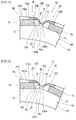
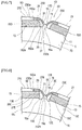
- FIG. 1 is a partial front view of a rotor (a front face with respect to a magnetic plate face),
- FIG. 2 is a partial front view of the rotor at a shifted rotational position, and
- FIG. 3 is a partial front view illustrating a dimensional relationship.
- FIG. 1 is also used for explanation of a method of evaluating centrifugal strength mentioned later and therefore also illustrates hatching of a fixed portion and an arrow of a loading direction.
- the rotor core 3 of the rotor 1 used for an electric motor is formed by stacking a plurality of the magnetic plates 5.
- Each magnetic plate 5 has the body portion 7 that is formed using material with high magnetic permeability such as silicon steel sheet in an annular shape such as disk or ring.
- the silicon steel sheet composing the body portion 7 has the compositions (percentage by mass) of Si: 2 to 4 and the reminder: iron and unavoidable impurities. Meanwhile, other materials may be used as the material of the magnetic plate 5.
- recessed portions 11 are formed on the circular outer peripheral edge 9 at a predetermined interval in the circumferential direction.
- the recessed portions 11 is formed into a shape which is gradually cut in a portion between the magnetic pole portions.
- a magnet slot 13 is formed inside the outer peripheral edge 9 as the opening in the circumferential direction to hold the magnet.
- a plurality of the magnet slots 13 are formed so as to be elongated in a tangential direction as the circumferential direction and are arranged at a predetermined interval in the circumferential direction.
- the permanent magnet 15 is held through an adhesive.
- a pair of permanent magnets may be held.
- the permanent magnet 15 extends in a magnetic-plate-stacking direction and has the cross-section that is formed into an approximately rectangular shape and that is elongated in the circumferential direction of the body portion 7. A plurality of the permanent magnets are held by the magnet slots 13, thereby to be arranged at a predetermined interval in the circumferential direction of the body portion 7.
- the magnet slot 13 is provided with an adhesive region 17 on each side of a region of the permanent magnet 15.
- the adhesive region 17 adjoins the bridge portion 19 and the bridge portion 19 is positioned between the magnet slot 13 and the recessed portion 11 of the outer peripheral edge 9 of the body portion 7.
- a pair of the bridge portions 19 have inner end sides in a radial direction of the body portion 7, the inner end sides being integrated with each other as a joint portion 19a.
- the radial width of the magnetic pole portion 21 between the outer peripheral edge 9 of the body portion 7 and the magnet slot 13 is set to be smaller than the radial sectional width of the permanent magnet 15.
- the comparison between the radial width of the magnetic pole portion 21 and the radial sectional width of the permanent magnet 15 is conducted using dimensions at the center of the magnetic pole as the position of the maximum width of the magnetic pole portion 21.
- the higher hardness portion 23 is provided to span from the bridge portion 19 to the magnetic pole portion 21.
- the higher hardness portion 23 is formed on each end of the magnet slot 13 in the circumferential direction of the body portion 7.
- the higher hardness portion 23 is formed into the hook shape along the end corner 13a of the opening 13 and has the radial maximum width being formed to be a smaller width than the radial sectional width of the permanent magnet 15. According to the embodiment, the maximum width in the whole higher hardness portion 23 is formed to be smaller than the radial sectional width of the permanent magnet 15. However, only the radial maximum width of the higher hardness portion 23 may be formed to be a smaller width than the radial sectional width of the permanent magnet 15 and the width of the higher hardness portion 23 between the magnet slots 13 may be formed to be larger than the radial sectional width of the permanent magnet 15.
- the higher hardness portion 23 is set by the compression working to have the higher hardness than the general portion of the body portion 7 other than the higher hardness portion 23.
- the higher hardness portion 23 is processed by the compression working with the compression rate of 5 to 25% relative to the thickness of the general portion of the body portion 7 that is, for example, 0.1 to 0.5mm.
- the higher hardness portion 23 is set to be 1.3 to 2.3 times higher than the hardness of the general part of the body portion 7 in Vickers hardness. In particular, the hardness of the higher hardness portion 23 is 250 to 390Hv.
- the higher hardness portion 23 is 0.4 to 0.8 times fewer than the general part of the body portion 7 in the density of the magnetic flux in the magnetic field of 4000A/m.
- the higher hardness portion 23 is set in the region spanning from the first edge 25 and the second edge 27 to the third edge 29 and the fourth edge 31.
- the first edge 25 is a part positioned along the circumferential direction on the outer peripheral side of the body portion 7 at the circumferential end of the magnet slot 13.
- the second edge 27 is a part of the bridge portion 19 positioned on the edge being continuous to the first edge 25 on the circumferential end edge 15a side of the permanent magnet 15.
- the third edge 29 is a part on the outer peripheral edge 9 side of the body portion 7 corresponding to the first edge 25.
- the fourth edge 31 is an outer part of the bridge portion 19 between the magnet slots 13.
- the higher hardness portion spans the width of the entire portion extending from the magnetic pole portion 21 to the bridge portion 19 in a formation range of the higher hardness portion 23.
- the formation range of the higher hardness portion 23 may be formed partly in the width direction from the magnetic pole portion 21 to the bridge portion 19.
- the formation range may be formed partly in the width direction only on one of the magnetic pole portion 21 and the bridge portion 19 and be formed entirely in the width direction on the other thereof.
- the formation range may be formed as a core portion with higher hardness only onto the midportion in the width direction in a case where the formation range is formed partly in the width direction on the magnetic pole portion 21 and/or the bridge portion 19.
- the higher hardness portion 23 has the extent in the circumferential direction of the body portion 7, the extent being set so as to exceed the boundary 33 ( FIG. 3 ) that leads along the end edge 15a of the permanent magnet 15 to the outer peripheral edge 9 side and enter the center side of the magnetic pole portion 21.
- the outer peripheral edge 9 side is the third edge 29 of the recessed portion 11 and is positioned inward relative to the outer peripheral edge 9 (for example, radially inward relative to the outer peripheral line of the rotor) in the radial direction of the body portion 7 as mentioned later.
- the higher hardness portion 23 has the end edge 23a ( FIG. 2 ) in the circumferential direction of the body portion 7, the end edge being slanted from the magnet slot 13 side toward the outer peripheral edge 9 of the body portion 7 so as to gradually enter the center side of the magnetic pole portion 21.
- the slanted end edge 23a of the hardness portion 23 reaches the outer peripheral edge 9 of the body portion 7 at the starting point 11 a of the recessed portion 11.
- the starting point 11 a is the point on the outer peripheral edge 9 from which the cut-in form starts so that the recessed portion 11 gradually deviates from the circular outer peripheral edge 9 (for example, the outer peripheral line of the rotor) toward the radial inside.
- the higher hardness portion 23 has the end edge 23b in the radial direction of the body portion 7 that is positioned onto a boundary between the higher hardness portion and the joint portion 19a.
- the end edges 23b slanted and facing each other are set so that a distance between the edges gradually expands toward the inside in the radial direction of the body portion 7.
- the higher hardness portion 23 has the length of L1 in the direction along the end edge 15a of the permanent magnet 15 between the magnet slots 13 and the length of L2 overlapping the permanent magnet 15 on the edge along the magnet slot 13 in the circumferential direction of the body portion 7.
- One end of L1 agrees with the edge of the permanent magnet 15 on the magnetic pole portion 21 side and the other end is the tip end of the end edge 23b in the direction along the end edge 15a.
- L1 is set more than 1/2 of the radial sectional width of the permanent magnet 15 and L2 is set to 1/6 or less of the circumferential sectional length of the permanent magnet 15.
- FIG. 4 is a partial front view of a rotor corresponding to FIGs. 2 and 3 .
- the same components as the shape example 1 are represented with the same reference numerals and corresponding components are represented with the same reference numerals with "A", to avoid repetition in a description.
- the extent of the higher hardness portion 23A in the circumferential direction of the body portion 7 is set up to the boundary 33A that straightly leads along the end edge 15a of the permanent magnet 15 to the outer peripheral edge 9A.
- the end edge 23Aa of the higher hardness portion 23A in the circumferential direction of the body portion 7A is positioned onto the boundary 33A.
- FIG. 5 is a partial front view of a rotor corresponding to FIGs. 2 and 3 .
- the same components as the shape example 1 are represented with the same reference numerals and corresponding components are represented with the same reference numerals with "B", to avoid repetition in a description.
- the extent of the higher hardness portion 23B in the circumferential direction of the body portion 7B is set so as to exceed the boundary 33B that leads along the end edge 15a of the permanent magnet 15 to the outer peripheral edge 9B and enter the center side of the magnetic pole portion 21.
- the end edge 23Ba of the higher hardness portion 23B in the circumferential direction of the body portion 7 is set in parallel with the boundary 33B.
- FIG. 6 is a partial front view of a rotor corresponding to FIGs. 2 and 3 .
- the same components as the shape example 1 are represented with the same reference numerals and corresponding components are represented with the same reference numerals with "C", to avoid repetition in a description.
- the setting of the end edge 23Cb of the higher hardness portion 23C is changed on the inner side in the radial direction of the body portion 7 with respect to the shape example 3.
- the end edge 23Cb is positioned away from the joint portion 19a in the radial direction of the body portion 7C, and the end edges 23Cb facing each other are approximately parallel with the end edge 15a of the permanent magnet 15.
- FIG. 7 is a partial front view of a rotor corresponding to FIGs. 2 and 3 .
- the same components as the shape example 1 are represented with the same reference numerals and corresponding components are represented with the same reference numerals with "D", to avoid repetition in a description.
- the higher hardness portion 23D is in common with the shape example 3 and the permanent magnet 15D has chamfered portions 15Db.
- FIG. 8 is a partial front view of a rotor corresponding to FIGs. 2 and 3 .
- the same components as the shape example 1 are represented with the same reference numerals and corresponding components are represented with the same reference numerals with "E", to avoid repetition in a description.
- the adhesive region 17E is enlarged so as to enclose the end portion 15c of the permanent magnet 15 compared with the shape example 3.
- FIG. 9 is a partial front view of a rotor corresponding to FIGs. 2 and 3 .
- the same components as the shape example 1 are represented with the same reference numerals and corresponding components are represented with the same reference numerals with "F", to avoid repetition in a description.
- the higher hardness portion 23F is set in the region spanning from the first edge 25F and the second edge 27F to the third edge 29F and the fourth edge 31 F.
- the first edge 25F is the part positioned along the circumferential direction at the circumferential end of the magnet slot 13F.
- the second edge 27F is the part of the bridge portion 19 positioned on the same border as the first edge 25F.
- the third edge 29F is the part on the outer peripheral edge 9F side of the body portion 7F corresponding to the first edge 25F.
- the fourth edge 31 F is the outer part of the bridge portion 19F between the magnet slots 13F.
- the third edge 29F is not the edge of the recessed portion unlike the shape example 1, but is the part of the outer peripheral edge 9F (on the outer peripheral line of the rotor).
- the magnetic plate 5F is not provided with adhesive regions in the magnet slot 13 and the sectional shape of the permanent magnet 15F is formed so as to match with the magnet slot 13F. Since the permanent magnet 15F is fitted to and held by the magnet slot 13F, the higher hardness portion 23F is set to have the hook shape in which the first edge 25 F and the second edge 27F are orthogonal with each other along the end 15Fc of the permanent magnet 15F.
- the end edge 23Fa of the higher hardness portion 23F in the circumferential direction has the same setting as the shape example 3 and the end edge 23Fb in the radial direction is set so as to enter the joint portion 19Fa.
- the end edge 23Fb is in the circumferential direction of the body portion 7F like the long side in the cross-section of the permanent magnet 15F.
- FIG. 10 is a partial front view of a rotor corresponding to FIGs. 2 and 3 .
- the same components as the shape example 1 are represented with the same reference numerals and corresponding components are represented with the same reference numerals with "G", to avoid repetition in a description.
- the body portion 7G has no recessed portion and the higher hardness portion 23G is set in the region spanning from the first edge 25G positioned along the circumferential direction at the circumferential end of the magnet slot 13G and the second edge 27G being the part of the bridge portion 19G on the same border as the first edge to the third edge 29G on the outer peripheral edge 9G side of the body portion 7G corresponding to the first edge 25G and the interposition between the magnet slots 13G.
- the higher hardness portion 23G has the T-shape.
- the third edges 29G are continuous to each other between the magnet slots 13G.
- the bridge portion 19G is not the whole central portion of the T-shape.
- the bridge portions 19G of a pair of the higher hardness portions 23G are integrated with each other to form the central portion of the T-shape.
- the circumferential width of the bridge portion 19G is 1/2 of the circumferential width of the T-shape.
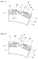
- FIG. 11 is a partial front view of a rotor corresponding to FIGs. 2 and 3 according to the comparative example 1.
- the comparative example has basically the same as the shape example 3 and only the representative numerals being the same as those of the shape example 3 are represented.
- the length L2 of the edge along the magnet slot 13 in the circumferential direction of the body portion 7B is set to be over 1/6 of the circumferential sectional length of the permanent magnet 15 in comparison with the shape example 3.
- FIG. 12 is a partial front view of a rotor corresponding to FIGs. 2 and 3 according to the comparative example 2.
- the comparative example has basically the same as the shape example 3 and only the representative numerals being the same as those of the shape example 3 are represented.
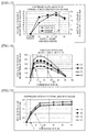
- FIG. 13 is a graph in which shape examples of the embodiment and shape example of the comparative example are compared with each other in rate of increase in magnet tensile yield load being a surrogate parameter for centrifugal strength and in rate of increase in voltage (hereinafter referred to as rotation induction voltage), which is a surrogate parameter for effective magnetic flux, induced by rotating the rotor with power of a different system from a stator in the stator to which no power is supplied.
- FIG. 14 is a graph in which the shape examples of the embodiment and the shape example of the comparative example are compared with each other in relationship between a compression rate at the time of processing to the higher hardness portion and the rate of increase in magnet tensile yield load.
- FIG. 15 is a graph in which the shape examples of the embodiment and the shape example of the comparative example are compared with each other in relationship between the compression rate and the rate of increase in rotation induction voltage.
- a relation with displacement load when radially outward displacing the jig as the arrow is represented with a diagram, a proportional limit of the diagram is defined as the yield load, and the size thereof is substituted for the evaluation of the centrifugal strength.
- the amount of the effective magnetic flux caused by generation torque of a motor is evaluated with the size of the rotation induction voltage as the surrogate parameter.
- the abscissa represents the shape examples (1) to (4) and the ordinate represents the rate % of increase in magnet tensile yield load and the rate % of increase in rotation induction voltage.
- (1): the shape example 2 of the embodiment 1, (2): the shape example 3 of the embodiment 1, (3): the shape example 1 of the embodiment 1, and (4): the shape example of the comparative example 1 are chosen.
- the compression rate of the higher hardness portion 23 is 14%.
- the areas of the higher hardness portions are set as (1) ⁇ (2) ⁇ (3) ⁇ (4) and the compression load becomes large as the area increases in the case of the same compression rate.
- the rate of increase becomes maximum at (3). If the area is larger than that, the rate of increase declines to cause inefficient in processing energy (high cost).
- the abscissa represents the compression rate and the ordinate represents the rate % of increase in magnet tensile yield load. Chosen examples are the same as FIG. 13 .
- the rate of increase more than 20% that is a market demand is satisfied from the compression rate of 5%.
- the bridge portion holding the permanent magnet 15 has a market demand for increasing the strength by at least approximate 20% as the arrow II in order to be as thin as possible and reduce leakage flux.
- the rate of increase in yield load is lower than that of the compression rate of 5% and causes inefficient in processing energy (production cost) of the compression working.
- the upper limit of the compression rate is set to 25% as mentioned above.
- the abscissa represents the compression rate and the ordinate represents the rate % of increase in rotation induction voltage. Chosen examples are the same as FIG. 13 .
- the comparative example 1 of (4) satisfies the demand for the magnet tensile yield load at the compression rate more than 5% of the arrow I. It, however, has the rate of increase in rotation induction voltage under required 1% (arrow II) that is out of the allowable range. It is not recognized as effective performance unless the rotation induction voltage as the surrogate parameter for the effective magnetic flux raises more than 1% by reducing the leakage flux.
- the shape examples 2, 3 and 1 of (1) to (3) of the embodiment are within the allowable range.
- the comparative example 1 of (4) is excluded and the setting is as 0 ⁇ L2 ⁇ 1/6 in view of the performance.
- L 1 > 1 / 2
- FIG. 16 is a graph in which the shape examples of the embodiment and a shape example of the comparative example are compared with each other in relationship between the compression rate and the rate of increase in magnet tensile yield load.
- FIG. 17 is a graph in which the shape examples and the comparative example are compared with each other in relationship between the compression rate and the rate of increase in rotation induction voltage.
- the abscissa represents the compression rate and the ordinate represents the rate % of increase in magnet tensile yield load.
- shape examples (5): the shape example of the comparative example 2, (6): the shape example 4 of the embodiment 1, and (2): the shape example 3 of the embodiment 1 are chosen.
- the rate of increase in yield load of the higher hardness portion 23B of the comparative example 2 does not reach 20% whereas the shape examples 4 and 3 of the embodiment 1 have the rate of increase of 20% or more.
- the abscissa represents the compression rate and the ordinate represents the rate % of increase in rotation induction voltage. Chosen examples are the same as FIG. 16 .
- the rate of increase in induction voltage of the higher hardness portion 23B of the comparative example 2 does not reach 1% in the compression rate 5% whereas the shape examples 4 and 3 of the embodiment 1 have the rate of increase of 1 % or more in the compression rate 5 to 25%.
- the comparative example 2 is excluded in the rate of increase in yield load and induction voltage, and the setting is as L1 ⁇ 1/2 in view of the performance.
- the rotation induction voltage includes higher harmonic waves and a higher harmonic voltage factor (hereinafter referred to as HVF) is introduced and evaluated as a parameter indicating percentage content of the higher harmonic waves.
- HVF is expressed by an expression 1.
- the abscissa represents the shape examples (1) to (4) and the ordinate represents the rate % of decrease in HVF.
- (1): the shape example 2 of the embodiment 1, (2): the shape example 3 of the embodiment 1, (3): the shape example 1 of the embodiment 1, and (4): the shape example of the comparative example 1 are chosen and the compression rate of the higher hardness portion 23 is 14% similar to the above.
- a relevant portion is compressed and compression load is required for that.
- the areas of the higher hardness portions are set as (1) ⁇ (2) ⁇ (3) ⁇ (4) and the compression load becomes large as the area increases in the case of the same compression rate.
- the higher harmonic voltage factor reduces as the area increases.
- the abscissa represents the compression rate and the ordinate represents the rate of decrease in HVF.
- Chosen shape examples are the same as the previous figure. In the same shape, if the higher hardness portion has the aforementioned compression rate range of 5 to 25%, the higher harmonic voltage factor is reduced relative to one without a higher hardness portion.
- the HVF varies according to the range of the higher hardness portion on the magnetic pole portion 21 side.
- the effect on the HVF is negligible in the range of the higher hardness portion on the bridge portion 19 side.
- the range of the present invention is enough for the higher hardness portion on the bridge portion 19 side. Therefore, in the shape examples 1 to 8, the higher harmonic waves included in magnetic flux distribution generated by the permanent magnet 15 on the outer peripheral surface of the rotor are reduced to prevent iron loss.
- the higher hardness portion 23 is formed from the bridge portion 19 toward the magnetic pole portion 21 to lower a magnetic property at this portion. Accordingly, the magnetic flux is mostly generated in a vertical direction relative to the long side in the cross-section of the permanent magnet 15 i.e. a circumferential direction of the rotor at the magnetic pole portion, to reduce the ineffective magnetic flux on the bridge portion 19 side and increase the effective magnetic flux for the rotation of the rotor.
- the higher hardness portion 23 to the body portion 7 is formed in advance by compressing a portion scheduled to be the higher hardness portion 23 before forming an outline of the body portion 7 from a plate material.
- the higher hardness portion 23 may be formed after forming the outline of the body portion 7.
- the body portion 7 may be applied to one having a plurality of divided bodies being connected together and arranged annularly.
- the magnetic plate 5 used for the rotor core of the motor the magnetic plate having the body portion 7 formed into the annular shape, the rotor core in which a plurality of the magnetic plates are stacked one on another and permanent magnets whose cross-section is approximately rectangular and is elongated in the circumferential direction of the body portion 7 are held by a plurality of the magnet slots 13 being formed so as to be elongated in the circumferential direction inside the outer peripheral edge 9 and being arranged at the predetermined interval in the circumferential direction.
- the magnet plate includes the magnetic pole portion 21 being set between the outer peripheral edge 9 of the body portion 7 and the magnet slot 13 and having the radial width being set so as to be smaller than the radial sectional width of the permanent magnet 15, and the higher hardness portion 23, relative to the general portion, being formed into the hook shape along the end corner of the magnet slot 13 and having the smaller width than the radial sectional width of the permanent magnet 15.
- the width of the magnetic pole portion 21 is set to be smaller than the radial sectional width of the permanent magnet 15, to reduce magnetic resistance of the magnetic pole portion 21 and increase the effective magnetic flux for the rotation of the rotor.
- the width of the higher hardness portion 23 is smaller than the radial sectional width of the permanent magnet 15 to further accurately prevent and activate ineffective magnetic flux.
- the magnet slot is not limited to the strict rectangular shape, and, for example, it may be a slight arc shape on a concentric circle with the rotor.
- the arrangement and the number of the magnetic slots are appropriately chosen according to a use of the electric motor.
Landscapes
- Engineering & Computer Science (AREA)
- Power Engineering (AREA)
- Manufacturing & Machinery (AREA)
- Permanent Field Magnets Of Synchronous Machinery (AREA)
Abstract
Description
- The present invention relates to a magnetic plate used for a rotor core of a motor and a method for manufacturing the same.
- In recent years, in accordance with advances in new technology for a wide variety of electrical equipment, electric vehicles, hybrid vehicles, robots and the like, performance required for motors or electric generators used for them becomes highly developed. For example, in industrial motors, electric vehicles, hybrid vehicles, or the like, there is a need for high torque, high output, space-saving and the like.
- Accordingly, there is a conventional rotor of a motor disclosed in
Patent document 1 as illustrated inFIGs. 20 and 21. FIG. 20 is a perspective view illustrating the rotor andFIG. 21 is a conceptual view illustrating magnetic flux distribution. - The
rotor 101 includes arotor core 105 in which a plurality ofmagnetic plates 103 having a circular shape as an annular shape are stacked one on another and permanent magnets 109 (hatched parts in both drawings correspond to cross-sections of the magnets extending in a magnetic-plate-stacking direction) held inopenings 107 of the rotor core. Therotor 101 is inserted into a stator (not illustrated) that forms a rotation magnetic field so that the rotation magnetic field in the stator according to supplied power interlinks with magnetic flux generated on an outer peripheral surface of the rotor core according to thepermanent magnets 109 to rotate therotor 101 according to repulsion and attraction. - In the
rotor 101, if radial widths ofmagnetic pole portions 103b formed between thepermanent magnets 109 and an outerperipheral edge 103a of themagnetic plate 103 are minimized, magnetic resistance with respect to the stator interlinking with the magnetic flux is reduced to increase a magnetic field that is effective in torque. This allows the torque to become higher or the rotor to be downsized if the torque is constant. That is, it is advantageous for increase in torque per motor volume (hereinafter referred to as torque density). - However, the reduction in the radial width of the
magnetic pole portion 103b is likely to cause plastic deformation at end corner portions etc. of theopening 107 due to stress concentration based on centrifugal force of thepermanent magnet 109 etc. at the time of the rotation, reduces so-called centrifugal strength, and lowers the maximum number of rotation capable of resisting the centrifugal force. As a result, there is a limit on improvement of output per motor volume (hereinafter referred to as output density) and on downsizing. - Further, in the vicinity of the
end portion 109a of thepermanent magnet 109, there is a problem of inefficient formation ofmagnetic flux 110 that is formed so as to make a short circuit in the rotor, not to interlink with the stator, and not to contribute to the rotation torque of the rotor. - Further, in the rotor incorporating the
permanent magnet 109 having a rectangular cross-section, the magnetic flux distribution caused on the outer peripheral surface becomes a rectangular wave shape including many higher harmonic waves and there is also a problem of increase in higher harmonic iron loss. - Contrary to this, a
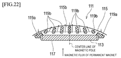
rotor 111 disclosed inPatent document 2 is proposed as illustrated inFIG. 22 . - In the
rotor 111, magnetic-flux-controllingportions opening 117 of amagnetic plate 115 holding apermanent magnet 113 and in amagnetic pole portion 115b so as to thin a thickness of the magnetic plate. - With this, magnetic flux distribution on a surface of the
rotor 111 is converted into a sine wave to prevent a torque pulsatory motion. - However, if the magnetic-flux-controlling
portions - On the other hand, the magnetic-flux-controlling
portions 119a at the end corners of theopening 117 may be formed by hardening portions likePatent document 3. - However, the shape of the magnetic-flux-controlling
portions 119a ofPatent document 2 is not preferred for higher torque density, higher output density and downsizing and there is a limit on downsizing due to the reduction of the width of themagnetic pole portion 115b. -
- PATENT DOCUMENT 1:
JP2003-304670A - PATENT DOCUMENT 2:
JP2012-105410A - PATENT DOCUMENT 3:
JP2004-7943A - A problem to be solved is that: the reduction in the radial width of the magnetic pole portion for higher torque is likely to cause plastic deformation at the end corner portions of the opening on which the stress concentration is generated based on the centrifugal force of the permanent magnet at the time of the rotation, reduces the centrifugal strength, and lowers the maximum number of rotation capable of resisting the centrifugal force, and this results in a limit on improvement of the output density and on downsizing; in the vicinity of the end portion of the opening, ineffective magnetic flux is formed so as not to contribute to the rotation torque of the rotor; and in the rotor incorporating the permanent magnet having the rectangular cross-section, the magnetic flux distribution caused on the outer peripheral surface becomes the rectangular wave shape including the many higher harmonic waves to increase iron loss.
- The present invention, in order to be able to contribute to higher torque density, higher output density, and downsizing and prevent ineffective magnetic field and higher harmonic waves, provides a magnetic plate used for a rotor core of a motor, the magnetic plate having a body portion formed into an annular shape, the rotor core in which a plurality of the magnetic plates are stacked one on another and permanent magnets whose cross-section is approximately rectangular and is elongated in a circumferential direction of the body portion are held by a plurality of openings being formed so as to be elongated in the circumferential direction inside an outer peripheral edge and being arranged at a predetermined interval in the circumferential direction. The magnetic plate includes a magnetic pole portion being set between the outer peripheral edge of the body portion and the opening and having a radial width being set so as to be smaller than a rotor radial width (length of a short side. Hereinafter referred to as a radial sectional width of the permanent magnet) in a cross-section of the permanent magnet, and a higher hardness portion being set to be formed into a hook shape along an end corner of the opening and have a radial maximum width being a smaller width than the radial sectional width of the permanent magnet.
- The magnetic plate of the present invention, because of the aforementioned configuration, allows a width of a portion spanning from the higher hardness portion being formed into the hook shape along the end corner of the opening to the magnetic pole portion to be set to be smaller than the radial sectional width of the permanent magnet, thereby to reduce magnetic resistance at the magnetic pole portion. The higher hardness portion being formed into the hook shape along the end corner of the opening improves centrifugal strength (resistance to plastic deformation) of the opening, prevents and activates ineffective magnetic flux that does not contribute to rotor rotation torque around the end corner of the opening, and prevent higher harmonic waves included in magnetic flux distribution generated on an outer peripheral surface of the rotor by the permanent magnet having the rectangular cross section.
- Therefore, it contributes to higher torque, higher output and downsizing etc. required for industrial motors, electric vehicles and hybrid vehicles etc.
-
- [
FIG. 1 ] It is a partial front view of a rotor. (Embodiment 1) - [
FIG. 2 ] It is a partial front view of the rotor at a shifted rotational position. (Embodiment 1) - [
FIG. 3 ] It is a partial front view illustrating a dimensional relationship. (Embodiment 1) - [
FIG. 4 ] It is a partial front view of a rotor. (Embodiment 1) - [
FIG. 5 ] It is a partial front view of a rotor. (Embodiment 1) - [
FIG. 6 ] It is a partial front view of a rotor. (Embodiment 1) - [
FIG. 7 ] It is a partial front view of a rotor. (Embodiment 1) - [
FIG. 8 ] It is a partial front view of a rotor. (Embodiment 1) - [
FIG. 9 ] It is a partial front view of a rotor. (Embodiment 1) - [
FIG. 10 ] It is a partial front view of a rotor. (Embodiment 1) - [
FIG. 11 ] It is a partial front view of a rotor. (Comparative example) - [
FIG. 12 ] It is a partial front view of a rotor. (Comparative example) - [
FIG. 13 ] It is a graph in which shape examples of the embodiment and a shape example of the comparative example are compared with each other in rate of increase in yield load and rotation induction voltage. - [
FIG. 14 ] It is a graph in which the shape examples of the embodiment and the shape example of the comparative example are compared with each other in relationship between a compression rate and a rate of increase in magnet tensile yield load. - [
FIG. 15 ] It is a graph in which the shape examples of the embodiment and the shape example of the comparative example are compared with each other in relationship between the compression rate and the rate of increase in rotation induction voltage. - [
FIG. 16 ] It is a graph in which shape examples of the embodiment and a shape example of the comparative example are compared with each other in relationship between a compression rate and a rate of increase in magnet tensile yield load. - [
FIG. 17 ] It is a graph in which the shape examples and the comparative example are compared with each other in relationship between the compression rate and a rate of increase in rotation induction voltage. - [
FIG. 18 ] It is a graph illustrating a compressed shape and a rate of decrease in higher harmonic voltage factor. - [
FIG. 19 ] It is a graph illustrating the compression rate and the rate of decrease in higher harmonic voltage factor. - [
FIG. 20 ] It is a perspective view of a rotor. (Related art) - [
FIG. 21 ] It is a conceptual diagram of formation of a magnetic field. (Related art) - [
FIG. 22 ] It is a partial front view of a rotor. (Related art) - The object that is to be able to contribute to higher torque, higher output, and downsizing and prevent ineffective magnetic field and higher harmonic waves is accomplished by a magnetic plate used for a rotor core of a motor, the magnetic plate having a body portion formed into an annular shape, the rotor core in which a plurality of the magnetic plates are stacked one on another and permanent magnets whose cross-section is approximately rectangular and is elongated in a circumferential direction of the body portion are held by a plurality of openings being formed so as to be elongated in the circumferential direction inside an outer peripheral edge and being arranged at a predetermined interval in the circumferential direction. The magnetic plate includes a magnetic pole portion being set between the outer peripheral edge of the body portion and the opening and having a rotor radial width being set so as to be smaller than a radial sectional width of the permanent magnet, and a higher hardness portion being set to be formed into a hook shape along an end corner of the opening and have a radial maximum width being a smaller width than the radial sectional width of the permanent magnet to have relatively-high yield stress.
- The higher hardness portion may be set in a region spanning from a first edge positioned along the circumferential direction on an outer peripheral side of the body portion at a circumferential end of the opening and a second edge positioned on an edge being continuous to the first edge on a circumferential end edge side of the permanent magnet to a third edge on the outer peripheral edge side of the body portion corresponding to the first edge and a fourth edge of a bridge portion between the openings or an interposition between the openings.
- The higher hardness portion may have an extent in the circumferential direction of the body portion, the extent being set up to a boundary that leads along an end edge of the permanent magnet to the outer peripheral edge side or set so as to exceed the boundary and enter a center of the magnetic pole portion.
- The higher hardness portion may have an end edge in the circumferential direction of the body portion, the edge being slanted from the opening side toward the outer peripheral edge of the body portion so as to gradually enter a center side of the magnetic pole portion.
- The outer peripheral edge of the body portion may be provided with a recessed portion in the form of being gradually cut in a portion between the magnetic pole portions. The slanted end edge of the higher hardness portion may reach the outer peripheral edge of the body portion at a starting point of the gradually-cut-in form of the recessed portion.
- A length of the higher hardness portion in a direction along the end edge of the permanent magnet between the openings may be set more than 1/2 of the radial sectional width of the permanent magnet, and a length of the higher hardness portion overlapping the permanent magnet on an edge along the opening in the circumferential direction of the body portion may be set between 1/6 or less of a length (hereinafter referred to as circumferential sectional length of the permanent magnet) of a long side, which contacts with the magnetic pole portion, of the cross section of the permanent magnet in the rotor circumferential direction and 0. The higher hardness portion may be 1.3 to 2.3 times higher than a general part of the body portion in Vickers hardness.
- The higher hardness portion may be subjected to compression working with a compression rate of 5 to 25% with respect to a thickness of the general part of the body portion.
- The higher hardness portion may be 0.4 to 0.8 times fewer than the general part of the body portion in density of magnetic flux in a magnetic field of 4000A/m.
- The body portion of which a plurality of sheets are laminated may be made of a silicon steel sheet.
- The silicon steel sheet of the body portion may have compositions (percentage by mass) of Si: 2 to 4 and the reminder: iron and unavoidable impurities.
- The higher hardness portion may have hardness of 250 to 390 Hv.
- The body portion may have a thickness of 0.1 to 0.5 mm.
- The body portion may have a plurality of divided bodies being connected together and arranged annularly.
- The higher hardness portion may be formed at each end of the opening in the circumferential direction of the body portion.
-
FIG. 1 is a partial front view of a rotor (a front face with respect to a magnetic plate face),FIG. 2 is a partial front view of the rotor at a shifted rotational position, andFIG. 3 is a partial front view illustrating a dimensional relationship. In addition,FIG. 1 is also used for explanation of a method of evaluating centrifugal strength mentioned later and therefore also illustrates hatching of a fixed portion and an arrow of a loading direction. - As illustrated in
FIGs. 1 and 2 , therotor core 3 of therotor 1 used for an electric motor is formed by stacking a plurality of themagnetic plates 5. Eachmagnetic plate 5 has thebody portion 7 that is formed using material with high magnetic permeability such as silicon steel sheet in an annular shape such as disk or ring. The silicon steel sheet composing thebody portion 7 has the compositions (percentage by mass) of Si: 2 to 4 and the reminder: iron and unavoidable impurities. Meanwhile, other materials may be used as the material of themagnetic plate 5. - To the
body portion 7, recessedportions 11 are formed on the circular outerperipheral edge 9 at a predetermined interval in the circumferential direction. The recessedportions 11 is formed into a shape which is gradually cut in a portion between the magnetic pole portions. In each circumferential interval between the recessedportions 11, amagnet slot 13 is formed inside the outerperipheral edge 9 as the opening in the circumferential direction to hold the magnet. A plurality of themagnet slots 13 are formed so as to be elongated in a tangential direction as the circumferential direction and are arranged at a predetermined interval in the circumferential direction. In eachmagnet slot 13, thepermanent magnet 15 is held through an adhesive. In eachmagnet slot 13, a pair of permanent magnets may be held. - The
permanent magnet 15 extends in a magnetic-plate-stacking direction and has the cross-section that is formed into an approximately rectangular shape and that is elongated in the circumferential direction of thebody portion 7. A plurality of the permanent magnets are held by themagnet slots 13, thereby to be arranged at a predetermined interval in the circumferential direction of thebody portion 7. - The
magnet slot 13 is provided with anadhesive region 17 on each side of a region of thepermanent magnet 15. Theadhesive region 17 adjoins thebridge portion 19 and thebridge portion 19 is positioned between themagnet slot 13 and the recessedportion 11 of the outerperipheral edge 9 of thebody portion 7. In each interposition between themagnet slots 13, a pair of thebridge portions 19 have inner end sides in a radial direction of thebody portion 7, the inner end sides being integrated with each other as ajoint portion 19a. - The radial width of the
magnetic pole portion 21 between the outerperipheral edge 9 of thebody portion 7 and themagnet slot 13 is set to be smaller than the radial sectional width of thepermanent magnet 15. In this case, the comparison between the radial width of themagnetic pole portion 21 and the radial sectional width of thepermanent magnet 15 is conducted using dimensions at the center of the magnetic pole as the position of the maximum width of themagnetic pole portion 21. To thebody portion 7, thehigher hardness portion 23 is provided to span from thebridge portion 19 to themagnetic pole portion 21. Thehigher hardness portion 23 is formed on each end of themagnet slot 13 in the circumferential direction of thebody portion 7. - The
higher hardness portion 23 is formed into the hook shape along theend corner 13a of theopening 13 and has the radial maximum width being formed to be a smaller width than the radial sectional width of thepermanent magnet 15. According to the embodiment, the maximum width in the wholehigher hardness portion 23 is formed to be smaller than the radial sectional width of thepermanent magnet 15. However, only the radial maximum width of thehigher hardness portion 23 may be formed to be a smaller width than the radial sectional width of thepermanent magnet 15 and the width of thehigher hardness portion 23 between themagnet slots 13 may be formed to be larger than the radial sectional width of thepermanent magnet 15. - The
higher hardness portion 23 is set by the compression working to have the higher hardness than the general portion of thebody portion 7 other than thehigher hardness portion 23. Thehigher hardness portion 23 is processed by the compression working with the compression rate of 5 to 25% relative to the thickness of the general portion of thebody portion 7 that is, for example, 0.1 to 0.5mm. Thehigher hardness portion 23 is set to be 1.3 to 2.3 times higher than the hardness of the general part of thebody portion 7 in Vickers hardness. In particular, the hardness of thehigher hardness portion 23 is 250 to 390Hv. - According to the setting, the
higher hardness portion 23 is 0.4 to 0.8 times fewer than the general part of thebody portion 7 in the density of the magnetic flux in the magnetic field of 4000A/m. - As illustrated in
FIG. 2 , thehigher hardness portion 23 is set in the region spanning from thefirst edge 25 and thesecond edge 27 to thethird edge 29 and thefourth edge 31. - The
first edge 25 is a part positioned along the circumferential direction on the outer peripheral side of thebody portion 7 at the circumferential end of themagnet slot 13. Thesecond edge 27 is a part of thebridge portion 19 positioned on the edge being continuous to thefirst edge 25 on thecircumferential end edge 15a side of thepermanent magnet 15. Thethird edge 29 is a part on the outerperipheral edge 9 side of thebody portion 7 corresponding to thefirst edge 25. Thefourth edge 31 is an outer part of thebridge portion 19 between themagnet slots 13. - According to the embodiment, therefore, the higher hardness portion spans the width of the entire portion extending from the
magnetic pole portion 21 to thebridge portion 19 in a formation range of thehigher hardness portion 23. - However, the formation range of the
higher hardness portion 23 may be formed partly in the width direction from themagnetic pole portion 21 to thebridge portion 19. The formation range may be formed partly in the width direction only on one of themagnetic pole portion 21 and thebridge portion 19 and be formed entirely in the width direction on the other thereof. Further, the formation range may be formed as a core portion with higher hardness only onto the midportion in the width direction in a case where the formation range is formed partly in the width direction on themagnetic pole portion 21 and/or thebridge portion 19. - The
higher hardness portion 23 has the extent in the circumferential direction of thebody portion 7, the extent being set so as to exceed the boundary 33 (FIG. 3 ) that leads along theend edge 15a of thepermanent magnet 15 to the outerperipheral edge 9 side and enter the center side of themagnetic pole portion 21. In this case, the outerperipheral edge 9 side is thethird edge 29 of the recessedportion 11 and is positioned inward relative to the outer peripheral edge 9 (for example, radially inward relative to the outer peripheral line of the rotor) in the radial direction of thebody portion 7 as mentioned later. - The
higher hardness portion 23 has theend edge 23a (FIG. 2 ) in the circumferential direction of thebody portion 7, the end edge being slanted from themagnet slot 13 side toward the outerperipheral edge 9 of thebody portion 7 so as to gradually enter the center side of themagnetic pole portion 21. Theslanted end edge 23a of thehardness portion 23 reaches the outerperipheral edge 9 of thebody portion 7 at thestarting point 11 a of the recessedportion 11. Namely, thestarting point 11 a is the point on the outerperipheral edge 9 from which the cut-in form starts so that the recessedportion 11 gradually deviates from the circular outer peripheral edge 9 (for example, the outer peripheral line of the rotor) toward the radial inside. - The
higher hardness portion 23 has theend edge 23b in the radial direction of thebody portion 7 that is positioned onto a boundary between the higher hardness portion and thejoint portion 19a. The end edges 23b slanted and facing each other are set so that a distance between the edges gradually expands toward the inside in the radial direction of thebody portion 7. - In
FIG. 3 , thehigher hardness portion 23 has the length of L1 in the direction along theend edge 15a of thepermanent magnet 15 between themagnet slots 13 and the length of L2 overlapping thepermanent magnet 15 on the edge along themagnet slot 13 in the circumferential direction of thebody portion 7. One end of L1 agrees with the edge of thepermanent magnet 15 on themagnetic pole portion 21 side and the other end is the tip end of theend edge 23b in the direction along theend edge 15a. - L1 is set more than 1/2 of the radial sectional width of the
permanent magnet 15 and L2 is set to 1/6 or less of the circumferential sectional length of thepermanent magnet 15. -
FIG. 4 is a partial front view of a rotor corresponding toFIGs. 2 and3 . The same components as the shape example 1 are represented with the same reference numerals and corresponding components are represented with the same reference numerals with "A", to avoid repetition in a description. - In the
magnetic plate 5A according to the shape example 2 of theembodiment 1, the extent of thehigher hardness portion 23A in the circumferential direction of thebody portion 7 is set up to theboundary 33A that straightly leads along theend edge 15a of thepermanent magnet 15 to the outerperipheral edge 9A. The end edge 23Aa of thehigher hardness portion 23A in the circumferential direction of thebody portion 7A is positioned onto theboundary 33A. In this shape example 2, the end edge 23Aa and thestarting point 11 Aa of the recessedportion 11 A are positioned onto theboundary 33A. L1=0 is concluded. - The others are the same as the shape example 1.
-
FIG. 5 is a partial front view of a rotor corresponding toFIGs. 2 and3 . The same components as the shape example 1 are represented with the same reference numerals and corresponding components are represented with the same reference numerals with "B", to avoid repetition in a description. - In the
magnetic plate 5B according to the shape example 3 of theembodiment 1, the extent of thehigher hardness portion 23B in the circumferential direction of thebody portion 7B is set so as to exceed theboundary 33B that leads along theend edge 15a of thepermanent magnet 15 to the outerperipheral edge 9B and enter the center side of themagnetic pole portion 21. The end edge 23Ba of thehigher hardness portion 23B in the circumferential direction of thebody portion 7 is set in parallel with theboundary 33B. - The others are the same as the shape example 1.
-
FIG. 6 is a partial front view of a rotor corresponding toFIGs. 2 and3 . The same components as the shape example 1 are represented with the same reference numerals and corresponding components are represented with the same reference numerals with "C", to avoid repetition in a description. - In the
magnetic plate 5C according to the shape example 4 of theembodiment 1, the setting of the end edge 23Cb of thehigher hardness portion 23C is changed on the inner side in the radial direction of thebody portion 7 with respect to the shape example 3. The end edge 23Cb is positioned away from thejoint portion 19a in the radial direction of thebody portion 7C, and the end edges 23Cb facing each other are approximately parallel with theend edge 15a of thepermanent magnet 15. - The others are the same as the shape example 1.
-
FIG. 7 is a partial front view of a rotor corresponding toFIGs. 2 and3 . The same components as the shape example 1 are represented with the same reference numerals and corresponding components are represented with the same reference numerals with "D", to avoid repetition in a description. - In the magnetic plate 5D according to the shape example 5 of the
embodiment 1, thehigher hardness portion 23D is in common with the shape example 3 and thepermanent magnet 15D has chamfered portions 15Db. - The others are the same as the shape example 1.
-
FIG. 8 is a partial front view of a rotor corresponding toFIGs. 2 and3 . The same components as the shape example 1 are represented with the same reference numerals and corresponding components are represented with the same reference numerals with "E", to avoid repetition in a description. - In the
magnetic plate 5E according to the shape example 6 of theembodiment 1, theadhesive region 17E is enlarged so as to enclose theend portion 15c of thepermanent magnet 15 compared with the shape example 3. - The others are the same as the shape example 1.
-
FIG. 9 is a partial front view of a rotor corresponding toFIGs. 2 and3 . The same components as the shape example 1 are represented with the same reference numerals and corresponding components are represented with the same reference numerals with "F", to avoid repetition in a description. - In the
magnetic plate 5F according to the shape example 7 of theembodiment 1, thehigher hardness portion 23F is set in the region spanning from thefirst edge 25F and thesecond edge 27F to thethird edge 29F and thefourth edge 31 F. - The
first edge 25F is the part positioned along the circumferential direction at the circumferential end of themagnet slot 13F. Thesecond edge 27F is the part of thebridge portion 19 positioned on the same border as thefirst edge 25F. Thethird edge 29F is the part on the outerperipheral edge 9F side of thebody portion 7F corresponding to thefirst edge 25F. Thefourth edge 31 F is the outer part of thebridge portion 19F between themagnet slots 13F. - The
third edge 29F is not the edge of the recessed portion unlike the shape example 1, but is the part of the outerperipheral edge 9F (on the outer peripheral line of the rotor). - The
magnetic plate 5F is not provided with adhesive regions in themagnet slot 13 and the sectional shape of thepermanent magnet 15F is formed so as to match with themagnet slot 13F. Since thepermanent magnet 15F is fitted to and held by themagnet slot 13F, thehigher hardness portion 23F is set to have the hook shape in which thefirst edge 25 F and thesecond edge 27F are orthogonal with each other along the end 15Fc of thepermanent magnet 15F. - The end edge 23Fa of the
higher hardness portion 23F in the circumferential direction has the same setting as the shape example 3 and the end edge 23Fb in the radial direction is set so as to enter the joint portion 19Fa. The end edge 23Fb is in the circumferential direction of thebody portion 7F like the long side in the cross-section of thepermanent magnet 15F. - The others are the same as the shape example 1.
-
FIG. 10 is a partial front view of a rotor corresponding toFIGs. 2 and3 . The same components as the shape example 1 are represented with the same reference numerals and corresponding components are represented with the same reference numerals with "G", to avoid repetition in a description. - In the
magnetic plate 5G according to the shape example 8 of theembodiment 1, thebody portion 7G has no recessed portion and thehigher hardness portion 23G is set in the region spanning from thefirst edge 25G positioned along the circumferential direction at the circumferential end of themagnet slot 13G and thesecond edge 27G being the part of thebridge portion 19G on the same border as the first edge to thethird edge 29G on the outerperipheral edge 9G side of thebody portion 7G corresponding to thefirst edge 25G and the interposition between themagnet slots 13G. Thehigher hardness portion 23G has the T-shape. The third edges 29G are continuous to each other between themagnet slots 13G. - In addition, the
bridge portion 19G is not the whole central portion of the T-shape. Thebridge portions 19G of a pair of thehigher hardness portions 23G are integrated with each other to form the central portion of the T-shape. Thus, the circumferential width of thebridge portion 19G is 1/2 of the circumferential width of the T-shape. -
FIG. 11 is a partial front view of a rotor corresponding toFIGs. 2 and3 according to the comparative example 1. The comparative example has basically the same as the shape example 3 and only the representative numerals being the same as those of the shape example 3 are represented. - In the comparative example 1, the length L2 of the edge along the
magnet slot 13 in the circumferential direction of thebody portion 7B is set to be over 1/6 of the circumferential sectional length of thepermanent magnet 15 in comparison with the shape example 3. - The others are the same as the shape example 3.
-
FIG. 12 is a partial front view of a rotor corresponding toFIGs. 2 and3 according to the comparative example 2. The comparative example has basically the same as the shape example 3 and only the representative numerals being the same as those of the shape example 3 are represented. - In the comparative example 2, the length L1 in the direction along the
end edge 15a of thepermanent magnet 15 between themagnet slots 13 is under 1/2 of the radial sectional width of thepermanent magnet 15 in comparison with the shape example 3 and, for example, is set to L1=0. - The others are the same as the shape example 3.
-

-
FIG. 13 is a graph in which shape examples of the embodiment and shape example of the comparative example are compared with each other in rate of increase in magnet tensile yield load being a surrogate parameter for centrifugal strength and in rate of increase in voltage (hereinafter referred to as rotation induction voltage), which is a surrogate parameter for effective magnetic flux, induced by rotating the rotor with power of a different system from a stator in the stator to which no power is supplied.FIG. 14 is a graph in which the shape examples of the embodiment and the shape example of the comparative example are compared with each other in relationship between a compression rate at the time of processing to the higher hardness portion and the rate of increase in magnet tensile yield load.FIG. 15 is a graph in which the shape examples of the embodiment and the shape example of the comparative example are compared with each other in relationship between the compression rate and the rate of increase in rotation induction voltage. - Evaluation of the centrifugal strength is conducted as illustrated in
FIG. 1 . For effects in improving the centrifugal strength, the hatched region of the yoke portion 7a positioned inside with respect to themagnet slot 13 ofFIG. 1 is fixed and a jig simulating thepermanent magnet 15 is inserted into the opening. - A relation with displacement load when radially outward displacing the jig as the arrow is represented with a diagram, a proportional limit of the diagram is defined as the yield load, and the size thereof is substituted for the evaluation of the centrifugal strength.
- The amount of the effective magnetic flux caused by generation torque of a motor is evaluated with the size of the rotation induction voltage as the surrogate parameter.
- In
FIG. 13 , the abscissa represents the shape examples (1) to (4) and the ordinate represents the rate % of increase in magnet tensile yield load and the rate % of increase in rotation induction voltage. As the shape examples, (1): the shape example 2 of theembodiment 1, (2): the shape example 3 of theembodiment 1, (3): the shape example 1 of theembodiment 1, and (4): the shape example of the comparative example 1 are chosen. The compression rate of thehigher hardness portion 23 is 14%. - To have higher hardness, a relevant portion is compressed and compression load is required for that. The areas of the higher hardness portions are set as (1)<(2)<(3)<(4) and the compression load becomes large as the area increases in the case of the same compression rate. In both the magnet tensile yield load and the rotation induction voltage, the rate of increase becomes maximum at (3). If the area is larger than that, the rate of increase declines to cause inefficient in processing energy (high cost).
- Namely, a boundary is set as the arrow I to exclude the comparative example 1 of (4) and the setting is as 0<=L2<=1/6 in view of the processing energy.
- In
FIG. 14 , the abscissa represents the compression rate and the ordinate represents the rate % of increase in magnet tensile yield load. Chosen examples are the same asFIG. 13 . - As the arrow I in
FIG. 14 , the rate of increase more than 20% that is a market demand is satisfied from the compression rate of 5%. The bridge portion holding thepermanent magnet 15 has a market demand for increasing the strength by at least approximate 20% as the arrow II in order to be as thin as possible and reduce leakage flux. In the compression rate more than 25% of the arrow III, the rate of increase in yield load is lower than that of the compression rate of 5% and causes inefficient in processing energy (production cost) of the compression working. For this, the upper limit of the compression rate is set to 25% as mentioned above. - In
FIG. 15 , the abscissa represents the compression rate and the ordinate represents the rate % of increase in rotation induction voltage. Chosen examples are the same asFIG. 13 . - The comparative example 1 of (4) satisfies the demand for the magnet tensile yield load at the compression rate more than 5% of the arrow I. It, however, has the rate of increase in rotation induction voltage under required 1% (arrow II) that is out of the allowable range. It is not recognized as effective performance unless the rotation induction voltage as the surrogate parameter for the effective magnetic flux raises more than 1% by reducing the leakage flux.
- The shape examples 2, 3 and 1 of (1) to (3) of the embodiment are within the allowable range.
- Namely, the comparative example 1 of (4) is excluded and the setting is as 0⇐L2⇐1/6 in view of the performance.

-
FIG. 16 is a graph in which the shape examples of the embodiment and a shape example of the comparative example are compared with each other in relationship between the compression rate and the rate of increase in magnet tensile yield load.FIG. 17 is a graph in which the shape examples and the comparative example are compared with each other in relationship between the compression rate and the rate of increase in rotation induction voltage. - In
FIG. 16 , the abscissa represents the compression rate and the ordinate represents the rate % of increase in magnet tensile yield load. As the shape examples, (5): the shape example of the comparative example 2, (6): the shape example 4 of theembodiment 1, and (2): the shape example 3 of theembodiment 1 are chosen. - In the
compression rate 5 to 25%, the rate of increase in yield load of thehigher hardness portion 23B of the comparative example 2 does not reach 20% whereas the shape examples 4 and 3 of theembodiment 1 have the rate of increase of 20% or more. - In
FIG. 17 , the abscissa represents the compression rate and the ordinate represents the rate % of increase in rotation induction voltage. Chosen examples are the same asFIG. 16 . - The rate of increase in induction voltage of the
higher hardness portion 23B of the comparative example 2 does not reach 1% in thecompression rate 5% whereas the shape examples 4 and 3 of theembodiment 1 have the rate of increase of 1 % or more in thecompression rate 5 to 25%. - Namely, the comparative example 2 is excluded in the rate of increase in yield load and induction voltage, and the setting is as L1⇒1/2 in view of the performance.
- The rotation induction voltage includes higher harmonic waves and a higher harmonic voltage factor (hereinafter referred to as HVF) is introduced and evaluated as a parameter indicating percentage content of the higher harmonic waves. HVF is expressed by an
expression 1.
- Where,
- Un: rate of the higher harmonic voltage of the n-th order relative to fundamental wave voltage
- n: degree
- In
FIG. 18 , the abscissa represents the shape examples (1) to (4) and the ordinate represents the rate % of decrease in HVF. As the shape examples, (1): the shape example 2 of theembodiment 1, (2): the shape example 3 of theembodiment 1, (3): the shape example 1 of theembodiment 1, and (4): the shape example of the comparative example 1 are chosen and the compression rate of thehigher hardness portion 23 is 14% similar to the above. To have higher hardness, a relevant portion is compressed and compression load is required for that. The areas of the higher hardness portions are set as (1)<(2)<(3)<(4) and the compression load becomes large as the area increases in the case of the same compression rate. The higher harmonic voltage factor reduces as the area increases. - In
FIG. 19 , the abscissa represents the compression rate and the ordinate represents the rate of decrease in HVF. Chosen shape examples are the same as the previous figure. In the same shape, if the higher hardness portion has the aforementioned compression rate range of 5 to 25%, the higher harmonic voltage factor is reduced relative to one without a higher hardness portion. - Further, since magnetomotive force of the
permanent magnet 15 is generated in the radial direction, the HVF varies according to the range of the higher hardness portion on themagnetic pole portion 21 side. However, the effect on the HVF is negligible in the range of the higher hardness portion on thebridge portion 19 side. The range of the present invention is enough for the higher hardness portion on thebridge portion 19 side. Therefore, in the shape examples 1 to 8, the higher harmonic waves included in magnetic flux distribution generated by thepermanent magnet 15 on the outer peripheral surface of the rotor are reduced to prevent iron loss. - In the shape example 1, if the
permanent magnet 15 in which the outer peripheral side of the long sides in the cross-section of thepermanent magnet 15 is the North pole and the inner peripheral side thereof is the south pole is buried as illustrated inFIG. 1 , thehigher hardness portion 23 is formed from thebridge portion 19 toward themagnetic pole portion 21 to lower a magnetic property at this portion. Accordingly, the magnetic flux is mostly generated in a vertical direction relative to the long side in the cross-section of thepermanent magnet 15 i.e. a circumferential direction of the rotor at the magnetic pole portion, to reduce the ineffective magnetic flux on thebridge portion 19 side and increase the effective magnetic flux for the rotation of the rotor. - The same holds for the shape examples 2 to 8.
- Regarding the shape example 1, as the formation of the
higher hardness portion 23 to thebody portion 7, the higher hardness portion is formed in advance by compressing a portion scheduled to be thehigher hardness portion 23 before forming an outline of thebody portion 7 from a plate material. - Meanwhile, the
higher hardness portion 23 may be formed after forming the outline of thebody portion 7. - The same holds for the shape examples 2 to 8.
- The
body portion 7 may be applied to one having a plurality of divided bodies being connected together and arranged annularly. - According to the
embodiment 1 of the present invention, themagnetic plate 5 used for the rotor core of the motor, the magnetic plate having thebody portion 7 formed into the annular shape, the rotor core in which a plurality of the magnetic plates are stacked one on another and permanent magnets whose cross-section is approximately rectangular and is elongated in the circumferential direction of thebody portion 7 are held by a plurality of themagnet slots 13 being formed so as to be elongated in the circumferential direction inside the outerperipheral edge 9 and being arranged at the predetermined interval in the circumferential direction. The magnet plate includes themagnetic pole portion 21 being set between the outerperipheral edge 9 of thebody portion 7 and themagnet slot 13 and having the radial width being set so as to be smaller than the radial sectional width of thepermanent magnet 15, and thehigher hardness portion 23, relative to the general portion, being formed into the hook shape along the end corner of themagnet slot 13 and having the smaller width than the radial sectional width of thepermanent magnet 15. - Accordingly, the width of the
magnetic pole portion 21 is set to be smaller than the radial sectional width of thepermanent magnet 15, to reduce magnetic resistance of themagnetic pole portion 21 and increase the effective magnetic flux for the rotation of the rotor. - The same holds for the other
magnetic plates 5A to 5G. - It prevents and activates ineffective magnetic flux that does not contribute to the rotor rotation torque at the
bridge portion 19 around the end corner of themagnet slot 13. Further, the width of thehigher hardness portion 23 is smaller than the radial sectional width of thepermanent magnet 15 to further accurately prevent and activate ineffective magnetic flux. - The same holds for the other
magnetic plates 5A to 5G. - In addition, the magnet slot is not limited to the strict rectangular shape, and, for example, it may be a slight arc shape on a concentric circle with the rotor. The arrangement and the number of the magnetic slots are appropriately chosen according to a use of the electric motor.
-
- 1, 1A, 1B, 1C, 1D, 1E, 1F, 1G Rotor
- 3, 3A, 3B, 3C, 3D, 3E, 3F, 3G Rotor core
- 5, 5A, 5B, 5C, 5D, 5E, 5F, 5G Magnetic plate
- 7, 7A, 7B, 7C, 7D, 7E, 7F, 7G Body portion
- 9, 9A, 9B, 9C, 9D, 9E, 9F, 9G Outer peripheral edge
- 11, 11 A, 11 B, 11 C, 11 D, 11 E, 11 F Recessed portion
- 13, 13E, 13F, 13G Magnet slot (Opening)
- 15, 15D, 15F, 15G Permanent magnet
- 15a, 15Da, 15Fa, 15Ga End edge
- 19, 19F, 19G Bridge portion
- 21, 21 A, 21 B, 21C, 21 D, 21 E, 21 F, 21 G Magnet pole portion
- 23, 23A, 23B, 23C, 23D, 23E, 23F, 23G Higher hardness portion
- 23a, 23Aa, 23Ba, 23Ca, 23Da, 23Ea, 23Fa, 23Ga End edge
- 23b, 23Ab, 23Bb, 23Cb, 23Db, 23Eb, 23Fb, 23Gb End edge
- 25, 25E, 25F, 25G First edge
- 27, 27E, 27F, 27G Second edge
- 29, 29F, 29G Third edge
- 31, 31F, 31G Fourth edge
- 33, 33A, 33B Boundary
Claims (11)
- A magnetic plate used for a rotor core of a motor, the magnetic plate having a body portion formed into an annular shape, the rotor core in which a plurality of the magnetic plates are stacked one on another and permanent magnets whose cross-section is approximately rectangular and is elongated in a circumferential direction of the body portion are held by a plurality of openings being formed so as to be elongated in the circumferential direction inside an outer peripheral edge and being arranged at a predetermined interval in the circumferential direction, characterized in that
a magnetic pole portion is set between the outer peripheral edge of the body portion and the opening and has a radial width being set so as to be smaller than a radial sectional width of the permanent magnet; and
a higher hardness portion is set to be formed into a hook shape along an end corner of the opening and have a radial maximum width being a smaller width than the radial sectional width of the permanent magnet. - The magnetic plate according to claim 1, characterized in that
the higher hardness portion is set in a region spanning from a first edge positioned along the circumferential direction on an outer peripheral side of the body portion at a circumferential end of the opening and a second edge positioned on an edge being continuous to the first edge and on a circumferential end edge side of the permanent magnet to a third edge on the outer peripheral edge side of the body portion corresponding to the first edge and a fourth edge of a bridge portion between the openings or an interposition between the openings. - The magnetic plate according to claim 1 or 2, characterized in that
the higher hardness portion has an extent in the circumferential direction of the body portion, the extent being set up to a boundary that leads along an end edge of the permanent magnet to the outer peripheral edge or set so as to exceed the boundary and enter a center side of the magnetic pole portion. - The magnetic plate according to any one of claims 1 to 3, characterized in that
the higher hardness portion has an end edge in the circumferential direction of the body portion, the edge being slanted from the opening side toward the outer peripheral edge of the body portion so as to gradually enter a center side of the magnetic pole portion. - The magnetic plate according to any one of claims 1 to 4, characterized in that
the outer peripheral edge of the body portion is provided with a recessed portion in the form of being gradually cut in a portion between the magnetic pole portions. - The magnetic plate according to of claim 5, characterized in that
the slanted end edge of the higher hardness portion reaches the outer peripheral edge of the body portion at the starting point of the gradually-cut-in form of the recessed portion. - The magnetic plate according to any one of claims 1 to 6, characterized in that
a length of the higher hardness portion in a direction along the end edge of the permanent magnet between the openings is set more than 1/2 of the radial sectional width of the permanent magnet, and
a length of a part of the higher hardness portion overlapping the permanent magnet on an edge along the opening in the circumferential direction of the body portion is set between 1/6 or less of a circumferential sectional length of the permanent magnet and 0. - The magnetic plate according to any one of claims 1 to 7, characterized in that
the higher hardness portion is 0.4 to 0.8 times fewer than a general part of the body portion in density of magnetic flux in a magnetic field of 4000A/m. - The magnetic plate according to any one of claims 1 to 8, characterized in that
a thickness of the body portion is 0.1 to 0.5 mm. - The magnetic plate according to any one of claims 1 to 9, characterized in that
the body portion has a plurality of divided bodies being connected together and arranged annularly. - A method of manufacturing the magnetic plate according to any one of claims 1 to 10, characterized in that
the higher hardness portion is formed in advance by compressing a portion scheduled to be the higher hardness portion before forming an outline of the body portion from a plate material.
Applications Claiming Priority (2)
| Application Number | Priority Date | Filing Date | Title |
|---|---|---|---|
| JP2013086140 | 2013-04-16 | ||
| PCT/JP2014/002135 WO2014171133A1 (en) | 2013-04-16 | 2014-04-15 | Magnetic plate used for rotor core of motor and method for manufacturing magnetic plate |
Publications (2)
| Publication Number | Publication Date |
|---|---|
| EP2988395A1 true EP2988395A1 (en) | 2016-02-24 |
| EP2988395A4 EP2988395A4 (en) | 2017-03-22 |
Family
ID=51731096
Family Applications (1)
| Application Number | Title | Priority Date | Filing Date |
|---|---|---|---|
| EP14784870.9A Withdrawn EP2988395A4 (en) | 2013-04-16 | 2014-04-15 | Magnetic plate used for rotor core of motor and method for manufacturing magnetic plate |
Country Status (5)
| Country | Link |
|---|---|
| US (1) | US9570948B2 (en) |
| EP (1) | EP2988395A4 (en) |
| JP (1) | JP5855792B2 (en) |
| CN (1) | CN105164896B (en) |
| WO (1) | WO2014171133A1 (en) |
Families Citing this family (11)
| Publication number | Priority date | Publication date | Assignee | Title |
|---|---|---|---|---|
| JP6147430B2 (en) * | 2014-06-11 | 2017-06-14 | 三菱電機株式会社 | Permanent magnet embedded motor |
| DE112017001847T5 (en) | 2016-06-03 | 2018-12-27 | Aisin Aw Co., Ltd. | rotor |
| DE102017103619A1 (en) * | 2017-02-22 | 2018-08-23 | Ebm-Papst St. Georgen Gmbh & Co. Kg | Electric motor, inner rotor and rotor plate |
| JP6858845B2 (en) * | 2017-05-01 | 2021-04-14 | 三菱電機株式会社 | Rotors, electric motors, compressors and air conditioners |
| JP7063916B2 (en) | 2017-12-07 | 2022-05-09 | 三菱電機株式会社 | How to manufacture rotors, motors, compressors, air conditioners, and rotors |
| US11177725B2 (en) * | 2018-06-19 | 2021-11-16 | Toyota Jidosha Kabushiki Kaisha | Interior permanent-magnet motor and method for manufacturing the same |
| JP7266495B2 (en) * | 2019-08-21 | 2023-04-28 | 日本製鉄株式会社 | motor |
| JP7348086B2 (en) * | 2020-01-14 | 2023-09-20 | 日立Astemo株式会社 | Rotating electric machines and on-vehicle electric motor systems |
| JP7283447B2 (en) * | 2020-06-11 | 2023-05-30 | トヨタ自動車株式会社 | ROTOR MANUFACTURING METHOD AND ROTOR MANUFACTURING APPARATUS |
| JP7338570B2 (en) * | 2020-07-01 | 2023-09-05 | トヨタ自動車株式会社 | ROTOR FOR ROTATING MACHINE AND MANUFACTURING METHOD THEREOF |
| JP7638434B2 (en) * | 2022-02-16 | 2025-03-03 | 三菱電機株式会社 | Permanent magnet rotor |
Family Cites Families (21)
| Publication number | Priority date | Publication date | Assignee | Title |
|---|---|---|---|---|
| US4434546A (en) * | 1979-09-21 | 1984-03-06 | General Electric Company | Method of making a core |
| US4570333A (en) * | 1983-10-28 | 1986-02-18 | General Electric Company | Method of making a permanent magnet rotor |
| JPH08331784A (en) * | 1995-03-24 | 1996-12-13 | Hitachi Metals Ltd | Permanent magnet field type rotary machine |
| JP3308828B2 (en) * | 1996-10-18 | 2002-07-29 | 株式会社日立製作所 | Permanent magnet rotating electric machine and electric vehicle using the same |
| US6332932B1 (en) * | 1999-04-20 | 2001-12-25 | Sumitomo Special Metals Co., Ltd. | Punch, powder pressing apparatus and powder pressing method |
| CN1102670C (en) * | 1999-06-16 | 2003-03-05 | 住友金属工业株式会社 | Non-directional electromagnetic steel sheet, and method for mfg. same |
| JP2001218400A (en) * | 2000-02-07 | 2001-08-10 | Shinko Electric Co Ltd | Permanent magnet type high-speed rotating machine |
| DE10108192A1 (en) * | 2001-02-21 | 2002-08-29 | Bosch Gmbh Robert | workpiece |
| JP2003304670A (en) | 2002-04-09 | 2003-10-24 | Toyota Motor Corp | Method of manufacturing rotor for rotating machine |
| JP3951905B2 (en) * | 2002-04-25 | 2007-08-01 | 日産自動車株式会社 | Magnetic steel sheet forming body for rotor core, rotor for built-in permanent magnet type rotating electric machine using the same, method for producing electromagnetic steel sheet forming body for rotor core, and permanent magnet built-in type rotating electric machine |
| WO2007080888A1 (en) * | 2006-01-10 | 2007-07-19 | Mitsuba Corporation | Rotating machine |
| JP4692428B2 (en) * | 2006-07-21 | 2011-06-01 | 株式会社デンソー | Rotor for rotating electrical machine for vehicle and manufacturing method thereof |
| JP2009268328A (en) * | 2008-04-30 | 2009-11-12 | Meidensha Corp | Magnet fixing structure of permanent magnet synchronous rotating electric machine |
| JP2010016961A (en) * | 2008-07-02 | 2010-01-21 | Mitsubishi Electric Corp | Rotor of permanent magnet embedded motor and its manufacturing method |
| JP5493675B2 (en) * | 2009-02-09 | 2014-05-14 | 株式会社ジェイテクト | Electric motor and rotor |
| JP5292271B2 (en) * | 2009-12-24 | 2013-09-18 | 株式会社日立製作所 | Permanent magnet rotating electric machine |
| JP5478461B2 (en) | 2010-11-09 | 2014-04-23 | 三菱電機株式会社 | Electric motor and compressor |
| JP5731251B2 (en) * | 2011-03-25 | 2015-06-10 | アスモ株式会社 | Rotor and motor |
| US8310126B1 (en) * | 2011-10-27 | 2012-11-13 | Motor Patent Licensors, LLC | Radial flux permanent magnet AC motor/generator |
| HUE054387T2 (en) * | 2011-11-29 | 2021-09-28 | Sumitomo Bakelite Co | Resin composition for fixing, rotor, automobile, and method for manufacturing rotor |
| JP2015012679A (en) * | 2013-06-28 | 2015-01-19 | 株式会社日立製作所 | Axial gap type rotating electrical machine |
-
2014
- 2014-04-15 EP EP14784870.9A patent/EP2988395A4/en not_active Withdrawn
- 2014-04-15 JP JP2015512308A patent/JP5855792B2/en not_active Expired - Fee Related
- 2014-04-15 US US14/785,168 patent/US9570948B2/en not_active Expired - Fee Related
- 2014-04-15 CN CN201480021179.7A patent/CN105164896B/en not_active Expired - Fee Related
- 2014-04-15 WO PCT/JP2014/002135 patent/WO2014171133A1/en not_active Ceased
Also Published As
| Publication number | Publication date |
|---|---|
| WO2014171133A1 (en) | 2014-10-23 |
| US20160065015A1 (en) | 2016-03-03 |
| JP5855792B2 (en) | 2016-02-09 |
| JPWO2014171133A1 (en) | 2017-02-16 |
| US9570948B2 (en) | 2017-02-14 |
| CN105164896A (en) | 2015-12-16 |
| CN105164896B (en) | 2017-08-18 |
| EP2988395A4 (en) | 2017-03-22 |
Similar Documents
| Publication | Publication Date | Title |
|---|---|---|
| US9570948B2 (en) | Magnetic plate used for rotor core of motor and method for manufacturing magnetic plate | |
| JP7568943B2 (en) | Laminated core and rotating electrical machine | |
| CN102754307B (en) | Permanent magnet, motor rotor or stator, dynamo-electric machine | |
| US10003228B2 (en) | Interior permanent magnet machine with axially varying permanent magnet size | |
| CN113169640A (en) | Laminated core and rotating electrical machine | |
| CN102347656B (en) | Permanent magnet type rotary machine | |
| CN203942428U (en) | Permanent magnet motor | |
| JP5665660B2 (en) | Permanent magnet rotating electric machine | |
| US9444292B2 (en) | Electric motor and compressor with same | |
| JP5012155B2 (en) | Laminated core and rotating electric machine | |
| JP4709132B2 (en) | Rotor of permanent magnet embedded motor, motor for blower and motor for compressor | |
| JPWO2013061427A1 (en) | Rotor and permanent magnet embedded motor | |
| JP6018940B2 (en) | Rotor and motor | |
| JP5242720B2 (en) | Rotor of permanent magnet embedded motor | |
| EP2953240B1 (en) | Rotor and motor | |
| CN111316537B (en) | Permanent magnet type rotating electrical machine | |
| JP2011097759A (en) | Stator of permanent magnet type rotary electric machine | |
| US11108289B2 (en) | Rotor and motor | |
| JP2010045870A (en) | Rotating machine | |
| EP3309931B1 (en) | Permanent magnet-embedded motor and compressor | |
| JP5360224B2 (en) | Method for manufacturing electric motor rotor | |
| JP5353804B2 (en) | Axial gap type rotating electrical machine and manufacturing method thereof | |
| CN110620451B (en) | Rotors, motors and compressors | |
| JP6627520B2 (en) | Method of manufacturing rotor and rotor | |
| JPWO2013121786A1 (en) | Motor stator core |
Legal Events
| Date | Code | Title | Description |
|---|---|---|---|
| PUAI | Public reference made under article 153(3) epc to a published international application that has entered the european phase |
Free format text: ORIGINAL CODE: 0009012 |
|
| 17P | Request for examination filed |
Effective date: 20151026 |
|
| AK | Designated contracting states |
Kind code of ref document: A1 Designated state(s): AL AT BE BG CH CY CZ DE DK EE ES FI FR GB GR HR HU IE IS IT LI LT LU LV MC MK MT NL NO PL PT RO RS SE SI SK SM TR |
|
| AX | Request for extension of the european patent |
Extension state: BA ME |
|
| DAX | Request for extension of the european patent (deleted) | ||
| A4 | Supplementary search report drawn up and despatched |
Effective date: 20170216 |
|
| RIC1 | Information provided on ipc code assigned before grant |
Ipc: H02K 1/27 20060101AFI20170210BHEP Ipc: H02K 1/22 20060101ALI20170210BHEP |
|
| STAA | Information on the status of an ep patent application or granted ep patent |
Free format text: STATUS: EXAMINATION IS IN PROGRESS |
|
| 17Q | First examination report despatched |
Effective date: 20171013 |
|
| RIC1 | Information provided on ipc code assigned before grant |
Ipc: H02K 29/03 20060101ALI20200113BHEP Ipc: H02K 1/27 20060101AFI20200113BHEP |
|
| GRAP | Despatch of communication of intention to grant a patent |
Free format text: ORIGINAL CODE: EPIDOSNIGR1 |
|
| STAA | Information on the status of an ep patent application or granted ep patent |
Free format text: STATUS: GRANT OF PATENT IS INTENDED |
|
| INTG | Intention to grant announced |
Effective date: 20200225 |
|
| STAA | Information on the status of an ep patent application or granted ep patent |
Free format text: STATUS: THE APPLICATION IS DEEMED TO BE WITHDRAWN |
|
| 18D | Application deemed to be withdrawn |
Effective date: 20200707 |