EP2988304A1 - Imaging apparatus - Google Patents
Imaging apparatus Download PDFInfo
- Publication number
- EP2988304A1 EP2988304A1 EP15180601.5A EP15180601A EP2988304A1 EP 2988304 A1 EP2988304 A1 EP 2988304A1 EP 15180601 A EP15180601 A EP 15180601A EP 2988304 A1 EP2988304 A1 EP 2988304A1
- Authority
- EP
- European Patent Office
- Prior art keywords
- image
- supplemental
- shooting mode
- main
- main image
- Prior art date
- Legal status (The legal status is an assumption and is not a legal conclusion. Google has not performed a legal analysis and makes no representation as to the accuracy of the status listed.)
- Granted
Links
- 238000003384 imaging method Methods 0.000 title claims abstract description 23
- 230000000153 supplemental effect Effects 0.000 claims abstract description 105
- 238000000034 method Methods 0.000 claims description 19
- 230000004044 response Effects 0.000 claims description 5
- 238000012544 monitoring process Methods 0.000 description 14
- 238000011156 evaluation Methods 0.000 description 9
- 101150053844 APP1 gene Proteins 0.000 description 8
- 101100189105 Homo sapiens PABPC4 gene Proteins 0.000 description 8
- 102100039424 Polyadenylate-binding protein 4 Human genes 0.000 description 8
- 238000005070 sampling Methods 0.000 description 8
- 239000007787 solid Substances 0.000 description 7
- 239000003550 marker Substances 0.000 description 4
- 238000010586 diagram Methods 0.000 description 3
- NJPPVKZQTLUDBO-UHFFFAOYSA-N novaluron Chemical compound C1=C(Cl)C(OC(F)(F)C(OC(F)(F)F)F)=CC=C1NC(=O)NC(=O)C1=C(F)C=CC=C1F NJPPVKZQTLUDBO-UHFFFAOYSA-N 0.000 description 3
- 239000013078 crystal Substances 0.000 description 2
- 239000011159 matrix material Substances 0.000 description 2
- 238000013139 quantization Methods 0.000 description 2
- 238000006243 chemical reaction Methods 0.000 description 1
- 230000009194 climbing Effects 0.000 description 1
- 230000000694 effects Effects 0.000 description 1
- 238000012854 evaluation process Methods 0.000 description 1
- 230000006870 function Effects 0.000 description 1
- 230000007704 transition Effects 0.000 description 1
Images



Classifications
-
- H—ELECTRICITY
- H04—ELECTRIC COMMUNICATION TECHNIQUE
- H04N—PICTORIAL COMMUNICATION, e.g. TELEVISION
- H04N5/00—Details of television systems
- H04N5/76—Television signal recording
- H04N5/91—Television signal processing therefor
-
- G—PHYSICS
- G11—INFORMATION STORAGE
- G11B—INFORMATION STORAGE BASED ON RELATIVE MOVEMENT BETWEEN RECORD CARRIER AND TRANSDUCER
- G11B27/00—Editing; Indexing; Addressing; Timing or synchronising; Monitoring; Measuring tape travel
- G11B27/02—Editing, e.g. varying the order of information signals recorded on, or reproduced from, record carriers
- G11B27/031—Electronic editing of digitised analogue information signals, e.g. audio or video signals
- G11B27/034—Electronic editing of digitised analogue information signals, e.g. audio or video signals on discs
-
- H—ELECTRICITY
- H04—ELECTRIC COMMUNICATION TECHNIQUE
- H04N—PICTORIAL COMMUNICATION, e.g. TELEVISION
- H04N23/00—Cameras or camera modules comprising electronic image sensors; Control thereof
- H04N23/60—Control of cameras or camera modules
- H04N23/63—Control of cameras or camera modules by using electronic viewfinders
- H04N23/631—Graphical user interfaces [GUI] specially adapted for controlling image capture or setting capture parameters
-
- H—ELECTRICITY
- H04—ELECTRIC COMMUNICATION TECHNIQUE
- H04N—PICTORIAL COMMUNICATION, e.g. TELEVISION
- H04N23/00—Cameras or camera modules comprising electronic image sensors; Control thereof
- H04N23/60—Control of cameras or camera modules
- H04N23/63—Control of cameras or camera modules by using electronic viewfinders
- H04N23/633—Control of cameras or camera modules by using electronic viewfinders for displaying additional information relating to control or operation of the camera
-
- H—ELECTRICITY
- H04—ELECTRIC COMMUNICATION TECHNIQUE
- H04N—PICTORIAL COMMUNICATION, e.g. TELEVISION
- H04N23/00—Cameras or camera modules comprising electronic image sensors; Control thereof
- H04N23/60—Control of cameras or camera modules
- H04N23/667—Camera operation mode switching, e.g. between still and video, sport and normal or high- and low-resolution modes
-
- H—ELECTRICITY
- H04—ELECTRIC COMMUNICATION TECHNIQUE
- H04N—PICTORIAL COMMUNICATION, e.g. TELEVISION
- H04N5/00—Details of television systems
- H04N5/76—Television signal recording
- H04N5/765—Interface circuits between an apparatus for recording and another apparatus
- H04N5/77—Interface circuits between an apparatus for recording and another apparatus between a recording apparatus and a television camera
- H04N5/772—Interface circuits between an apparatus for recording and another apparatus between a recording apparatus and a television camera the recording apparatus and the television camera being placed in the same enclosure
-
- H—ELECTRICITY
- H04—ELECTRIC COMMUNICATION TECHNIQUE
- H04N—PICTORIAL COMMUNICATION, e.g. TELEVISION
- H04N9/00—Details of colour television systems
- H04N9/79—Processing of colour television signals in connection with recording
- H04N9/80—Transformation of the television signal for recording, e.g. modulation, frequency changing; Inverse transformation for playback
- H04N9/804—Transformation of the television signal for recording, e.g. modulation, frequency changing; Inverse transformation for playback involving pulse code modulation of the colour picture signal components
- H04N9/8042—Transformation of the television signal for recording, e.g. modulation, frequency changing; Inverse transformation for playback involving pulse code modulation of the colour picture signal components involving data reduction
Definitions
- the present invention relates to an imaging apparatus that manages image data in association with each other.
- An apparatus that manages image files has been known by for example, Japanese Patent Publication No. 5141447 .
- This apparatus is configured to record two images of a main image and a sub-image recoded in an image file different from that of the main image in association with each other, and to display the main image and the sub-image in association with each other.
- This apparatus is also configured to determine the updating of the image when one of the images is updated.
- An object of the present invention is to provide an imaging apparatus that can manage two different image data of supplemental image data and main image data as one image file by adding the supplemental image data to an image file of the main image data.
- An imaging apparatus that records separately shot two images as one image file includes a clip image shooting mode that creates the one image file having one of the separately shot two images as a supplemental image of the other of the separately shot two images as a main image.
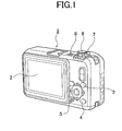
- FIG. 1 is a perspective view showing a back face of the digital still camera.
- a digital still camera 1 includes a back face and a top face.
- the back face of the digital still camera 1 includes a monitor screen 2 as a display screen, a shooting and reproduction switching button 3, a display button 4 as a reproduction section, a self-timer key 5, and various operation members.
- the top face of the digital still camera 1 includes a power source button 6, a mode setting dial 7, a shutter button 8, and various operation members.
- monitor screen 2 shooting and reproduction switching button 3
- display button 4 self-timer key 5
- power source button 6 shutter button 8
- the digital still camera 1 displays a through image on the monitor screen 2 by the after-described computer (CPU).
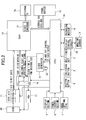
- the digital still camera 1 includes a solid state imaging element (CCD) 10 as illustrated in FIG. 2 .
- CCD solid state imaging element
- the solid state imaging element 10 photoelectrically converts the subject light into picture signals and outputs the picture signals to a sampling and analogue-digital convertor (CDS and A/D convertor) 11.
- CDS and A/D convertor analogue-digital convertor
- the sampling and analogue-digital convertor 11 correlatively double-samples the picture signals to eliminate noise signals, converts the signals into 10-bit image data, and outputs the image data to an image processor (DSP) 12.
- DSP image processor
- the image processor 12 executes known processes such as a white balance process, aperture emphasizing process, and interpolating process to the 10-bit image data sent from the sampling and analogue-digital convertor 11.
- the image processor 12 converts the 10-bit image data sent from the sampling and analogue-digital convertor 11 into a brightness signal Y and a color difference signal Cb and Cr, and temporally stores and accumulates the signals in a frame buffer memory 13.
- the image processor 12 includes a video encoder 14.
- the image data temporally stored and accumulated in the frame buffer memory 13 is sequentially read by the video encoder 14, is converted into video signals, and outputs to a display 15 such as an external TV.
- the solid state imaging element 10 is driven and scanned by a horizontal driving pulse output from a timing generator (TG) 16, a vertical driving pulse output from a vertical driver (VDr) 17, and an electric shutter pulse.
- TG timing generator
- VDr vertical driving pulse output from a vertical driver
- the digital still camera 1 is integrally controlled by a computer (CUP) 18.
- the shooting and reproduction switching button 3, the display button 4, the self-timer key 5, the other operation members, a recording medium 19, and a display control circuit 20 are connected to the computer 18.
- the computer 18 controls the timing generator 16, a clock generator 21, and the sampling and analogue-digital convertor 11 based on electric shutter pulses.
- the timing generator 16 outputs the vertical driving pulses to the vertical driver 17 and a predetermined clock to the sampling and analogue-digital convertor 11.
- the clock generator 21 is connected to a crystal oscillator 22 for driving a CCD.
- the clock generator 21 includes a not-shown frequency dividing circuit that divides a clock of an oscillating frequency of the crystal oscillator 22.
- the clock generator 21 outputs a driving pulse for driving the solid state imaging element to the timing generator 16.
- the timing generator 16 includes a frequency dividing circuit 23.
- the frequency dividing circuit 23 selectively divides the driving pulse for driving the solid state imaging element by one or two.
- the frequency dividing circuit 23 outputs a frequency divided clock to the image processor 12.
- the image processor 12 includes a not-shown internal counter. Since the operation and effect of the frequency dividing circuit 23 are irrelevant to the present invention, the detailed description thereof is omitted.
- the image processor 12 When the number of driving pulses by the counter reaches a predetermined count number, the image processor 12 outputs a horizontal reset signal and a vertical reset signal to the timing generator 16.
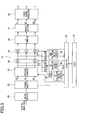
- the image processor 12 includes a color separator 25, signal interpolator 26, pedestal adjustor 27, white balance adjustor 28, digital gain adjustor 29, gamma convertor 30, matrix section 31, and video signal processor 32, as illustrated in FIG. 3 .
- the color separator 25 separates the 10-bit image data output from the sampling and analogue-digital convertor 11 into respective color components such as R, G, and B.
- the signal interpolator 26 executes a known interpolating process to the respective image data of R, G, and B.
- the pedestal adjustor 27 adjusts a black level of the respective image data of R, G, and B.
- the white balance adjustor 28 adjusts a white level of the respective image data of R, G, and B.
- the digital gain adjustor 29 adjusts a digital count value of the respective image data of R, G, and B by the gain set by the computer 18.
- the gamma convertor 30 executes ⁇ conversion of R, G, and B.
- the matrix section 31 separates the respective image data of R, G, and B into the color difference signal Cb and Cr and the brightness signal Y.
- the video signal processor 32 creates the video signal based on the color difference signal Cb and Cr and the brightness signal Y, and outputs the signals to the video encoder 14 and the display control circuit 20.
- the image processor 12 further includes a Y calculator 33, bypass filter (BPF) 34, AF evaluation value circuit 35, AE evaluation value circuit 36, Y calculator 37, AWB evaluation value circuit 38, and computer interface (CPU I/F) 39.
- BPF bypass filter
- the Y calculator 33 detects brightness data of the image data after the pedestal adjustment.
- the bypass filter 34 allows passage of only the brightness data of a predetermined frequency component in the brightness data detected by the Y calculator 33.
- the AF evaluation value circuit 35 outputs the integrated value of the brightness data passed through the bypass filter 34 as an AF evaluation value to the computer 18.
- the Y calculator 37 outputs the digital count value according to the brightness data detected by the Y calculator 33 as an AWB evaluation value to the computer 18.
- a focused position is detected by the solid state imaging element 10.
- the computer 18 detects a peak position of the AF evaluation values with a hill climbing servo method by sampling the focus evaluation values (AF evaluation value) showing the contrast of a subject. Since these automatic focusing process and exposure evaluation process are known processes, the detailed description thereof is omitted.
- the computer 18 executes the shooting mode that displays the through image on the monitor screen 2 for monitoring as illustrated in FIG. 4A .
- FIG. 4A shows that a vehicle 2A as a subject is displayed on the monitor screen 2 for monitoring.
- the digital still camera 1 includes a clip image shooting mode that creates one image file having one shot image as the supplemental image of the other shot image as the main image.
- the clip image shooting mode includes as shooting modes a supplemental image shooting mode that previously shoots an image as supplemental image data and a main image shooting mode that shoots an image as main image data after shooting the image as the supplemental image data.
- the supplemental image shooting mode (clip shooting mode) is set on the initial menu setting screen of the monitor screen 2.
- “Supplemental Image ON / OFF” is displayed on the initial menu setting screen along with various items.
- the computer 18 sets supplemental image shooting (clip image shooting) to an effective mode.
- the main image shooting mode and the supplemental image shooting mode are switched by the self-timer key 5.
- the self-timer key 5 operates as a switching key that switches the supplemental image shooting mode and the main image shooting mode. Note that in the main image shooting mode the shooting cannot be performed by the self-timer key 5 that presses a shutter after the elapse of a predetermined time.
- the computer 18 sets the shooting mode to a macro shooting mode that macro shoots the supplemental image illustrated in FIG. 4B .
- the computer 18 is set to a mode that shoots a subject image by enlarging the subject image.
- FIG. 4B shows that a number plate 2B of a vehicle as the supplemental image is displayed as a through image for monitoring.
- the computer 18 includes a determination part that determines the presence and absence of the supplemental image data.
- the computer 18 displays an icon 2C showing the presence of the supplemental image on the monitor screen 2 along with the vehicle 2A as the through image illustrated in FIG. 4C when the supplemental image is stored.
- the supplemental image data is temporarily accumulated and stored in the frame buffer memory 13 when the shutter button 8 is pressed under a predetermined condition before shooting the main image.
- the computer 18 reproduces and displays the number plate 2B as the supplemental image on the monitor screen 2 as illustrated in FIG. 4D when the self-timer key 5 is pressed while the icon 2C illustrated in FIG. 4C is displayed on the monitor screen 2.
- a user therefore can check a quality of the supplemental image to be added to the main image before shooting the main image.
- the display button 4 is used as a cancel button in the shooting mode.
- the supplemental image shooting mode in which the number plate 2B illustrated in FIG. 4B is displayed on the monitor screen 2 as a monitoring image
- the display button 4 when the display button 4 is pressed, the vehicle 2A illustrated in FIG. 4A is displayed as the through image (monitoring image).
- the shooting mode returns to the main image shooting mode in which the vehicle 2A is displayed as the through image as illustrated in FIG. 4C .
- the computer 18 changes the shooting mode to the supplemental image shooting mode from a state in which the supplemental image is reproduced and displayed on the monitor screen 2.
- the shooting mode is changed to the supplemental image shooting mode in which the supplemental image is displayed as a monitoring image illustrated in FIG. 4B from a state in which the number plate 2B is reproduced and displayed as the supplemental image as illustrated in FIG. 4D .
- the door mirror of the vehicle can be obtained as the supplemental image.
- a plurality of supplemental images to be added to the main image can be obtained.
- the computer 18 also directly changes the shooting mode from the main image shooting mode to the supplemental image shooting mode in response to the operation of the self-timer key 5 when the supplemental image is not stored.
- the computer 18 determines the presence and absence of the supplemental image, and selects a file structure of compressed data when shooting the main image.
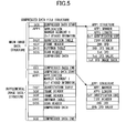
- FIG. 5 shows one example of the file structure of the compressed data.
- the file structure of the compressed data includes the main image data and the supplemental image data.
- the main image data includes SOI (compressed data start), APP1 (application and marker segment 1 (Exif attached information)), DQT (quantization table), SOF (frame header), DHT (Huffman table), SOS (scan header), compressed data, and EOI (compressed data end).
- the supplemental image data also includes SOI (compressed data start), APP1 (application and marker segment 1 (Exif attached information)), DQT (quantization table), SOFs (frame header), DHT (Huffman table), SOS (scan header), compressed data, and EOI (compressed data end).
- SOI compressed data start
- APP1 application and marker segment 1 (Exif attached information)
- DQT quantization table
- SOFs frame header
- DHT Huffman table
- SOS scan header
- compressed data and EOI (compressed data end).
- the structure of the APP1 of the main image data includes APP1 Marker, APP1 Length, Exif identification code, TIFF Header, 0th IFD, 0th IFD Value, 1st IFD, 1 st IFD Value, and 1 st IFD image data.
- the structure of the APP1 of the supplemental image data includes APP1 Marker, APP1 Length, Exif identification code, TIFE Header, 0th IFD, and 0th IFD Value.
- APP1 Marker APP1 Length
- Exif identification code TIFE Header
- TIFE Header 0th IFD
- IFD Value 0th IFD Value
- the computer 18 creates the compressed data of the supplemental image in addition to the compressed data of the main image after the shooting of the main image is completed when the supplemental image is stored.
- the computer creates only the compressed data of the main image in accordance with the file structure of the main image at the same time as the completion of the shooting of the main image when the supplemental image is not stored.
- FIG. 5 shows the file structure of the compressed data in which one supplemental image is added to one main image.
- a file structure in which a plurality of supplemental images is added to one main image is used, a plurality of supplemental images can be linked to one main image in one image file.
- the digital still camera 1 is set to the main image shooting mode in which the through image is displayed for monitoring as illustrated in FIG. 4A in S1.
- the computer 18 determines whether or not the self-timer key 5 is pressed in S2.
- the digital still camera 1 is changed to the supplemental image shooting mode from the main image shooting mode.
- the computer 18 determines the presence and absence of the supplemental image in S3.
- the main image shooting mode is maintained in S2 and S4 until the shutter button 8 is pressed in S4.
- the computer 18 displays the icon 2C on the monitor screen 2 on which the main image is displayed for monitoring as illustrated in FIG. 4C .
- the computer 18 executes the exposure process, obtains the image data after the exposure process is completed as the supplemental image data in S9, and temporary accumulates and stores the supplemental image data in the frame buffer memory 13 in S10.
- the computer 18 is changed to the main image shooting mode in S4.
- the icon 2C is displayed as illustrated in FIG. 4C .
- the supplemental image can be reliably obtained.
- the computer 18 determines whether or not the shutter button 8 is pressed. When the shutter button 8 is not pressed, the flow returns to S2 to determine whether or not the self-timer key 5 is pressed.
- the computer 18 executes the exposure process, and obtains the image data after the exposure process is completed as the main image data in S11. Next, the computer 18 determines the presence and absence of the supplemental image data in S12.
- the computer 18 compresses the main image data, creates the image file of Exif format, and records the file in the recording medium 19 in S 13.
- the computer 18 compresses the main image data, creates one image file by adding the supplemental image data to the main image data for creating the image file of Exif format, and records and stores the image file in the recording medium 19 in S14.
- the shooting mode is switched to the reproduction mode.
- the computer 18 reads the image file from the recording medium 19 in the reproduction mode.
- the reproduction mode as illustrated in FIG. 7A , the main image is reproduced and displayed on the monitor screen 2.
- the vehicle 2A is displayed as the main image.
- the supplemental image can be displayed on the monitor screen 2.
- the supplemental image data is stored, the supplemental image is reproduced and displayed as illustrated in FIG. 7B while the supplemental image is not reproduced and displayed on the monitor screen 2 when the supplemental image is not stored.
- the number plate 2B is displayed as the supplemental image as illustrated in FIG. 7B .
- size information 2D of the image file is displayed on the monitor screen 2 along with the main image as illustrated in FIG. 7C .
- the monitor screen 2 returns to the initial monitor screen 2 as illustrated in FIG. 7A .
- the main image, the main image with the camera memo, the supplemental image, the main image with the image size information, and the main image with the histogram information are toggled on the monitor screen 2 in order.
- a method of setting the camera memo on the initial menu setting screen in the monitor screen 2 is a known method, the detailed description thereof is omitted.
- a plurality of supplemental images and a main image can be linked in one file for creating and reproducing an image.
- the image can be easily managed.
- the digital still camera 1 is useful for creating an entire image and a detail image of a vehicle for selling used cars at an auction.
- the supplemental image and the main image can be reliably linked, and the supplemental image can be reproduced when reproducing the main image.
Landscapes
- Engineering & Computer Science (AREA)
- Multimedia (AREA)
- Signal Processing (AREA)
- Human Computer Interaction (AREA)
- Studio Devices (AREA)
- Television Signal Processing For Recording (AREA)
Abstract
Description
- The present invention relates to an imaging apparatus that manages image data in association with each other.
- An apparatus that manages image files has been known by for example, Japanese Patent Publication No.
5141447 - An object of the present invention is to provide an imaging apparatus that can manage two different image data of supplemental image data and main image data as one image file by adding the supplemental image data to an image file of the main image data.
- An imaging apparatus that records separately shot two images as one image file includes a clip image shooting mode that creates the one image file having one of the separately shot two images as a supplemental image of the other of the separately shot two images as a main image.
-
-
FIG. 1 is an external appearance view illustrating a digital still camera according to an embodiment of an imaging apparatus of the present invention, -
FIG. 2 is a block diagram for explaining the digital still camera illustrated inFIG. 1 , -
FIG. 3 is a block diagram showing main configurations of an image processor illustrated inFIG. 2 , -
FIGs 4A to 4D are views each showing one example of display of a monitor screen of the digital still camera illustrated inFIG. 1 , -
FIG. 4A shows that a vehicle as a main image is displayed as a through image for monitoring in a main image shooting mode, -
FIG. 4B shows that a number plate as a supplemental image is displayed for monitoring in a supplemental image shooting mode, -
FIG. 4C shows that an icon showing the presence of the shot supplemental image is displayed on the monitor screen on which the vehicle as the main image is displayed as the through image for monitoring in the main image shooting mode, -
FIG. 4D shows that the number plate as the supplemental image is reproduced and displayed in response to operation of a self-timer key when the supplemental image has been shot in a shooting mode, -
FIG. 5 is a view showing one example of a file structure of image data according to the embodiment of the present invention, -
FIG. 6 is a flowchart showing one example of a method of using a digital still camera according to the embodiment of the present invention, -
FIGs. 7A to 7C are views each showing one example of transition of the monitor screen by a display button illustrated inFIG. 1 in a reproduction mode switched by a shooting and reproduction switching button illustrated inFIG. 1 , -
FIG. 7A shows the monitor screen on which the main image is displayed, -
FIG. 7B shows the monitor screen on which the supplemental image is displayed, and -
FIG. 7C shows the monitor screen on which the main image is displayed along with an image size. - Hereinafter, an embodiment of a digital still camera (digital camera) as an imaging apparatus will be described with reference to the drawings.
- At first, an external appearance configuration of the digital still camera will be briefly described.
FIG. 1 is a perspective view showing a back face of the digital still camera. - Referring to
FIG. 1 , a digitalstill camera 1 includes a back face and a top face. The back face of thedigital still camera 1 includes amonitor screen 2 as a display screen, a shooting andreproduction switching button 3, adisplay button 4 as a reproduction section, a self-timer key 5, and various operation members. - The top face of the
digital still camera 1 includes apower source button 6, amode setting dial 7, ashutter button 8, and various operation members. - The functions of the
monitor screen 2, shooting andreproduction switching button 3,display button 4, self-timer key 5,power source button 6, andshutter button 8 will be described later. Since the other operation members are irrelevant to the present invention, the description thereof will be omitted. - When the
power source button 6 is turned on, the digitalstill camera 1 displays a through image on themonitor screen 2 by the after-described computer (CPU). - Next, the circuit block diagram of the digital
still camera 1 will be described. - The
digital still camera 1 includes a solid state imaging element (CCD) 10 as illustrated inFIG. 2 . - Light from a subject is imaged on the solid
state imaging element 10 through a not-shown lens. The solidstate imaging element 10 photoelectrically converts the subject light into picture signals and outputs the picture signals to a sampling and analogue-digital convertor (CDS and A/D convertor) 11. - The sampling and analogue-
digital convertor 11 correlatively double-samples the picture signals to eliminate noise signals, converts the signals into 10-bit image data, and outputs the image data to an image processor (DSP) 12. - The
image processor 12 executes known processes such as a white balance process, aperture emphasizing process, and interpolating process to the 10-bit image data sent from the sampling and analogue-digital convertor 11. - The
image processor 12 converts the 10-bit image data sent from the sampling and analogue-digital convertor 11 into a brightness signal Y and a color difference signal Cb and Cr, and temporally stores and accumulates the signals in aframe buffer memory 13. - While monitoring the digital still
camera 1, namely, while the through image is displayed on themonitor screen 2, these processes are repeated. Theimage processor 12 includes avideo encoder 14. - The image data temporally stored and accumulated in the
frame buffer memory 13 is sequentially read by thevideo encoder 14, is converted into video signals, and outputs to adisplay 15 such as an external TV. - The solid
state imaging element 10 is driven and scanned by a horizontal driving pulse output from a timing generator (TG) 16, a vertical driving pulse output from a vertical driver (VDr) 17, and an electric shutter pulse. - The
digital still camera 1 is integrally controlled by a computer (CUP) 18. The shooting andreproduction switching button 3, thedisplay button 4, the self-timer key 5, the other operation members, arecording medium 19, and adisplay control circuit 20 are connected to thecomputer 18. - The
computer 18 controls thetiming generator 16, aclock generator 21, and the sampling and analogue-digital convertor 11 based on electric shutter pulses. - The
timing generator 16 outputs the vertical driving pulses to thevertical driver 17 and a predetermined clock to the sampling and analogue-digital convertor 11. - The
clock generator 21 is connected to acrystal oscillator 22 for driving a CCD. Theclock generator 21 includes a not-shown frequency dividing circuit that divides a clock of an oscillating frequency of thecrystal oscillator 22. - The
clock generator 21 outputs a driving pulse for driving the solid state imaging element to thetiming generator 16. - The
timing generator 16 includes afrequency dividing circuit 23. The frequency dividingcircuit 23 selectively divides the driving pulse for driving the solid state imaging element by one or two. - The frequency dividing
circuit 23 outputs a frequency divided clock to theimage processor 12. Theimage processor 12 includes a not-shown internal counter. Since the operation and effect of thefrequency dividing circuit 23 are irrelevant to the present invention, the detailed description thereof is omitted. - When the number of driving pulses by the counter reaches a predetermined count number, the
image processor 12 outputs a horizontal reset signal and a vertical reset signal to thetiming generator 16. - The
image processor 12 includes acolor separator 25, signalinterpolator 26,pedestal adjustor 27,white balance adjustor 28,digital gain adjustor 29,gamma convertor 30,matrix section 31, andvideo signal processor 32, as illustrated inFIG. 3 . - The
color separator 25 separates the 10-bit image data output from the sampling and analogue-digital convertor 11 into respective color components such as R, G, and B. Thesignal interpolator 26 executes a known interpolating process to the respective image data of R, G, and B. - The
pedestal adjustor 27 adjusts a black level of the respective image data of R, G, and B. Thewhite balance adjustor 28 adjusts a white level of the respective image data of R, G, and B. Thedigital gain adjustor 29 adjusts a digital count value of the respective image data of R, G, and B by the gain set by thecomputer 18. - The
gamma convertor 30 executes γ conversion of R, G, and B. Thematrix section 31 separates the respective image data of R, G, and B into the color difference signal Cb and Cr and the brightness signal Y. Thevideo signal processor 32 creates the video signal based on the color difference signal Cb and Cr and the brightness signal Y, and outputs the signals to thevideo encoder 14 and thedisplay control circuit 20. - The
image processor 12 further includes aY calculator 33, bypass filter (BPF) 34, AFevaluation value circuit 35, AEevaluation value circuit 36,Y calculator 37, AWBevaluation value circuit 38, and computer interface (CPU I/F) 39. - The
Y calculator 33 detects brightness data of the image data after the pedestal adjustment. Thebypass filter 34 allows passage of only the brightness data of a predetermined frequency component in the brightness data detected by theY calculator 33. - The AF
evaluation value circuit 35 outputs the integrated value of the brightness data passed through thebypass filter 34 as an AF evaluation value to thecomputer 18. TheY calculator 37 outputs the digital count value according to the brightness data detected by theY calculator 33 as an AWB evaluation value to thecomputer 18. - A focused position is detected by the solid
state imaging element 10. Thecomputer 18 detects a peak position of the AF evaluation values with a hill climbing servo method by sampling the focus evaluation values (AF evaluation value) showing the contrast of a subject. Since these automatic focusing process and exposure evaluation process are known processes, the detailed description thereof is omitted. - Hereinafter, the details of the embodiment of the present invention will be described.
- When a power source of the digital
still camera 1 is turned on and a shooting mode is selected, thecomputer 18 executes the shooting mode that displays the through image on themonitor screen 2 for monitoring as illustrated inFIG. 4A . -
FIG. 4A shows that avehicle 2A as a subject is displayed on themonitor screen 2 for monitoring. - The digital
still camera 1 includes a clip image shooting mode that creates one image file having one shot image as the supplemental image of the other shot image as the main image. The clip image shooting mode includes as shooting modes a supplemental image shooting mode that previously shoots an image as supplemental image data and a main image shooting mode that shoots an image as main image data after shooting the image as the supplemental image data. - The supplemental image shooting mode (clip shooting mode) is set on the initial menu setting screen of the
monitor screen 2. - "Supplemental Image ON / OFF" is displayed on the initial menu setting screen along with various items. When "On" is selected in "Supplemental Image ON / OFF", the
computer 18 sets supplemental image shooting (clip image shooting) to an effective mode. - In this embodiment, the main image shooting mode and the supplemental image shooting mode are switched by the self-
timer key 5. Namely, the self-timer key 5 operates as a switching key that switches the supplemental image shooting mode and the main image shooting mode. Note that in the main image shooting mode the shooting cannot be performed by the self-timer key 5 that presses a shutter after the elapse of a predetermined time. - In the supplemental image shooting mode, the
computer 18 sets the shooting mode to a macro shooting mode that macro shoots the supplemental image illustrated inFIG. 4B . Namely, thecomputer 18 is set to a mode that shoots a subject image by enlarging the subject image.FIG. 4B shows that anumber plate 2B of a vehicle as the supplemental image is displayed as a through image for monitoring. - The
computer 18 includes a determination part that determines the presence and absence of the supplemental image data. In the main image shooting mode, thecomputer 18 displays anicon 2C showing the presence of the supplemental image on themonitor screen 2 along with thevehicle 2A as the through image illustrated inFIG. 4C when the supplemental image is stored. - The supplemental image data is temporarily accumulated and stored in the
frame buffer memory 13 when theshutter button 8 is pressed under a predetermined condition before shooting the main image. - The
computer 18 reproduces and displays thenumber plate 2B as the supplemental image on themonitor screen 2 as illustrated inFIG. 4D when the self-timer key 5 is pressed while theicon 2C illustrated inFIG. 4C is displayed on themonitor screen 2. A user therefore can check a quality of the supplemental image to be added to the main image before shooting the main image. - The
display button 4 is used as a cancel button in the shooting mode. In the supplemental image shooting mode in which thenumber plate 2B illustrated inFIG. 4B is displayed on themonitor screen 2 as a monitoring image, when thedisplay button 4 is pressed, thevehicle 2A illustrated inFIG. 4A is displayed as the through image (monitoring image). - When the
display button 4 is pressed while thenumber plate 2B is reproduced and displayed on themonitor screen 2 as illustrated inFIG. 4D , the shooting mode returns to the main image shooting mode in which thevehicle 2A is displayed as the through image as illustrated inFIG. 4C . - While the supplemental image is reproduced and displayed on the
monitor screen 2 as illustrated inFIG. 4D , when the self-timer key 5 as the switching key is pressed, thecomputer 18 changes the shooting mode to the supplemental image shooting mode from a state in which the supplemental image is reproduced and displayed on themonitor screen 2. - Namely, when the self-
timer key 5 is pressed while thenumber plate 2B as the supplemental image is displayed on themonitor screen 2 as illustrated inFIG. 4D , the shooting mode is changed to the supplemental image shooting mode in which the supplemental image is displayed as a monitoring image illustrated inFIG. 4B from a state in which thenumber plate 2B is reproduced and displayed as the supplemental image as illustrated inFIG. 4D . - In this case, when a subject for the supplemental image is changed from the
number plate 2B to a door mirror of a vehicle, the door mirror of the vehicle can be obtained as the supplemental image. In this embodiment, a plurality of supplemental images to be added to the main image can be obtained. - The
computer 18 also directly changes the shooting mode from the main image shooting mode to the supplemental image shooting mode in response to the operation of the self-timer key 5 when the supplemental image is not stored. - The
computer 18 determines the presence and absence of the supplemental image, and selects a file structure of compressed data when shooting the main image.FIG. 5 shows one example of the file structure of the compressed data. - The file structure of the compressed data includes the main image data and the supplemental image data. The main image data includes SOI (compressed data start), APP1 (application and marker segment 1 (Exif attached information)), DQT (quantization table), SOF (frame header), DHT (Huffman table), SOS (scan header), compressed data, and EOI (compressed data end).
- The supplemental image data also includes SOI (compressed data start), APP1 (application and marker segment 1 (Exif attached information)), DQT (quantization table), SOFs (frame header), DHT (Huffman table), SOS (scan header), compressed data, and EOI (compressed data end).
- The structure of the APP1 of the main image data includes APP1 Marker, APP1 Length, Exif identification code, TIFF Header, 0th IFD, 0th IFD Value, 1st IFD, 1 st IFD Value, and 1 st IFD image data.
- The structure of the APP1 of the supplemental image data includes APP1 Marker, APP1 Length, Exif identification code, TIFE Header, 0th IFD, and 0th IFD Value. In addition, since the respective items of the compressed data are known, the detailed description thereof is omitted.
- The
computer 18 creates the compressed data of the supplemental image in addition to the compressed data of the main image after the shooting of the main image is completed when the supplemental image is stored. The computer creates only the compressed data of the main image in accordance with the file structure of the main image at the same time as the completion of the shooting of the main image when the supplemental image is not stored. -
FIG. 5 shows the file structure of the compressed data in which one supplemental image is added to one main image. However, when a file structure in which a plurality of supplemental images is added to one main image is used, a plurality of supplemental images can be linked to one main image in one image file. - Hereinafter, the details of the shooting mode will be described with reference to the flowchart illustrated in
FIG. 6 . - When the
power source button 6 is turned on, the digitalstill camera 1 is set to the main image shooting mode in which the through image is displayed for monitoring as illustrated inFIG. 4A in S1. - Next, the
computer 18 determines whether or not the self-timer key 5 is pressed in S2. When the self-timer key 5 is pressed, the digitalstill camera 1 is changed to the supplemental image shooting mode from the main image shooting mode. Thecomputer 18 determines the presence and absence of the supplemental image in S3. When the self-timer key 5 is not pressed, the main image shooting mode is maintained in S2 and S4 until theshutter button 8 is pressed in S4. - When the supplemental image shot before shooting the main image is stored in S3, the
computer 18 displays theicon 2C on themonitor screen 2 on which the main image is displayed for monitoring as illustrated inFIG. 4C . - While the
icon 2C is displayed, when the self-timer key 5 is pressed in S2 and S3, the supplemental image is reproduced and displayed on themonitor screen 2 as illustrated inFIG. 4D in S5. The contents and the shooting quality of the supplemental image can be therefore reconfirmed before shooting the main image. - While the supplemental image is reproduced and displayed on the
monitor screen 2 as illustrated inFIG. 4D , when the self-timer key 5 is pressed in S6, themonitor screen 2 returns to themonitor screen 2 on which the supplemental image is displayed for monitoring as illustrated inFIG. 4B . Namely, thecomputer 18 determines whether or not theshutter button 8 is pressed in S8 after the reproduction display mode that reproduces and displays the supplemental image is switched to the supplemental image shooting mode that shoots the supplemental image in S7. - While the supplemental image is reproduced and displayed on the
monitor screen 2 as illustrated inFIG. 4D , when thedisplay button 4 is pressed, themonitor screen 2 returns to themonitor screen 2 for monitoring the main image as illustrated inFIG. 4C . Namely, while the supplemental image is reproduced and displayed as illustrated inFIG. 4D , when thedisplay button 4 is pressed, the flow proceeds to S2 and thecomputer 18 determines whether or not the self-timer key 5 is pressed in S2. - When the supplemental image is not stored in S3, the flow proceeds to S8. S8 is repeated until the
shutter button 8 is pressed. - When the
shutter button 8 is pressed in S8, thecomputer 18 executes the exposure process, obtains the image data after the exposure process is completed as the supplemental image data in S9, and temporary accumulates and stores the supplemental image data in theframe buffer memory 13 in S10. - Next, the flow returns to S1 and the
computer 18 executes the through image display process in S1. Then the flow proceeds to S2 and thecomputer 18 determines whether or not the self-timer key 5 is pressed in S2. - When the self-
timer key 5 is not pressed in S2, thecomputer 18 is changed to the main image shooting mode in S4. When the supplemental image is obtained, theicon 2C is displayed as illustrated inFIG. 4C . Thus, the supplemental image can be reliably obtained. - In the main image shooting mode in S4, the
computer 18 determines whether or not theshutter button 8 is pressed. When theshutter button 8 is not pressed, the flow returns to S2 to determine whether or not the self-timer key 5 is pressed. - When the
shutter button 8 is pressed in S4, thecomputer 18 executes the exposure process, and obtains the image data after the exposure process is completed as the main image data in S11. Next, thecomputer 18 determines the presence and absence of the supplemental image data in S12. - When the supplemental image data is not stored, the
computer 18 compresses the main image data, creates the image file of Exif format, and records the file in therecording medium 19 inS 13. - When the supplemental image data is stored, the
computer 18 compresses the main image data, creates one image file by adding the supplemental image data to the main image data for creating the image file of Exif format, and records and stores the image file in therecording medium 19 in S14. - After shooting, when the recording and
reproduction switching button 3 is pressed, the shooting mode is switched to the reproduction mode. Thecomputer 18 reads the image file from therecording medium 19 in the reproduction mode. In the reproduction mode, as illustrated inFIG. 7A , the main image is reproduced and displayed on themonitor screen 2. In this embodiment, thevehicle 2A is displayed as the main image. - While the main image is reproduced and displayed on the
monitor screen 2 and a camera memo is ON, when thedisplay button 4 as a reproducer is pressed, the camera memo and the main image are reproduced and displayed on themonitor screen 2. Namely, the text information is added to the main image. - While the camera memo and the main image are reproduced and displayed on the
monitor screen 2, when thedisplay button 4 is again pressed, the supplemental image can be displayed on themonitor screen 2. In this case, when the supplemental image data is stored, the supplemental image is reproduced and displayed as illustrated inFIG. 7B while the supplemental image is not reproduced and displayed on themonitor screen 2 when the supplemental image is not stored. In this embodiment, thenumber plate 2B is displayed as the supplemental image as illustrated inFIG. 7B . - While the supplemental image is displayed on the
monitor screen 2, when thedisplay button 4 is again pressed,size information 2D of the image file is displayed on themonitor screen 2 along with the main image as illustrated inFIG. 7C . - Next, when the
display button 4 is pressed, histogram is added, and the main image can be displayed on themonitor screen 2. In this case, when thedisplay button 4 is pressed, themonitor screen 2 returns to theinitial monitor screen 2 as illustrated inFIG. 7A . - Through the repetition of the pressing of the
display button 4, the main image, the main image with the camera memo, the supplemental image, the main image with the image size information, and the main image with the histogram information are toggled on themonitor screen 2 in order. In addition, since a method of setting the camera memo on the initial menu setting screen in themonitor screen 2 is a known method, the detailed description thereof is omitted. - According to the present invention, when both an entire image and a detail image are required, a plurality of supplemental images and a main image can be linked in one file for creating and reproducing an image. Thus, the image can be easily managed.
- The digital
still camera 1 according to the present embodiment is useful for creating an entire image and a detail image of a vehicle for selling used cars at an auction. - According to the embodiment of the present invention, the supplemental image and the main image can be reliably linked, and the supplemental image can be reproduced when reproducing the main image.
- Although the embodiment of the present invention has been described above, the present invention is not limited thereto. It should be appreciated that variations may be made in the embodiment described by persons skilled in the art without departing from the scope of the present invention.
Claims (10)
- An imaging apparatus (1) that records separately shot two images as one image file, the apparatus comprising a clip image shooting mode that creates the one image file having one of the separately shot two images as a supplemental image of the other of the separately shot two images as a main image.
- The imaging apparatus (1) according to claim 1, wherein
the clip image shooting mode includes a supplemental image shooting mode that obtains the image as supplemental image data and a main image shooting mode that obtains the image as main image data, and
wherein, in the main image shooting mode, the supplemental image data is added for creating an image file of the main image data, and the image file is recorded in a recording medium (19). - The imaging apparatus according to claim 2, wherein
the supplemental image is shot by macro shooting in the supplemental image shooting mode. - The imaging apparatus according to any one of claims 1 to 3 further comprising a determination part (18) that determines presence and absence of the supplemental image data,
wherein, in the main image shooting mode, when the supplemental image is stored, an icon showing the presence of the supplemental image is displayed on a display screen (2). - The imaging apparatus according to claim 4 further comprising a switching key (5) that switches the supplemental image shooting mode and the main image shooting mode,
wherein the determination part (18) reproduces and displays the supplemental image on the display screen (2) in response to operation of the switching key (5) while the icon is displayed on the display screen (2) in the main image shooting mode. - The imaging apparatus according to claim 5, wherein
the determination part (18) changes a shooting mode to the supplemental image shooting mode from a state in which the supplemental image is reproduced and displayed on the display screen (2) in response to the operation of the switching key (5) while the supplemental image is reproduced and displayed on the display screen (2). - The imaging apparatus according to any one of claims 4 to 6, wherein
the determination part (18) changes a shooting mode from the main image shooting mode to the supplemental image shooting mode in response to operation of a switching key (5) when the supplemental image is not stored. - The imaging apparatus according to any one of claims 1 to 7, wherein
the image file includes a plurality of supplemental images. - The imaging apparatus according to any one of claims 1 to 8 further comprising a reproduction section (4) that sequentially reproduces the supplemental image and the main image.
- A shooting method with a shooting mode that creates one image file having one of separately shot two images as a supplemental image of the other of the separately shot two images as a main image,
the shooting mode including:a step of obtaining the image as supplemental image data; anda step of obtaining the image as main image data,the method comprising adding the supplemental image data for creating an image file of the main image data, and recording the image file in a recording medium (19) in the main image shooting mode.
Applications Claiming Priority (1)
| Application Number | Priority Date | Filing Date | Title |
|---|---|---|---|
| JP2014166495A JP6451141B2 (en) | 2014-08-19 | 2014-08-19 | Imaging device |
Publications (2)
| Publication Number | Publication Date |
|---|---|
| EP2988304A1 true EP2988304A1 (en) | 2016-02-24 |
| EP2988304B1 EP2988304B1 (en) | 2020-05-06 |
Family
ID=53836457
Family Applications (1)
| Application Number | Title | Priority Date | Filing Date |
|---|---|---|---|
| EP15180601.5A Active EP2988304B1 (en) | 2014-08-19 | 2015-08-11 | Imaging apparatus |
Country Status (5)
| Country | Link |
|---|---|
| US (1) | US10122957B2 (en) |
| EP (1) | EP2988304B1 (en) |
| JP (1) | JP6451141B2 (en) |
| KR (1) | KR101680483B1 (en) |
| RU (1) | RU2604057C1 (en) |
Citations (7)
| Publication number | Priority date | Publication date | Assignee | Title |
|---|---|---|---|---|
| US20060072028A1 (en) * | 2004-10-01 | 2006-04-06 | Samsung Techwin Co., Ltd. | Method for operating a digital photographing apparatus using a touch screen and a digital photographing apparatus using the method |
| US20100134644A1 (en) * | 2008-11-28 | 2010-06-03 | Casio Computer Co., Ltd. | Image pick-up apparatus, method of producing file of obtained image, and recording medium |
| US20110018970A1 (en) * | 2009-07-21 | 2011-01-27 | Fujifilm Corporation | Compound-eye imaging apparatus |
| US20110018971A1 (en) * | 2009-07-21 | 2011-01-27 | Yuji Hasegawa | Compound-eye imaging apparatus |
| US20110234853A1 (en) * | 2010-03-26 | 2011-09-29 | Fujifilm Corporation | Imaging apparatus and display apparatus |
| US20110234881A1 (en) * | 2010-03-25 | 2011-09-29 | Fujifilm Corporation | Display apparatus |
| JP5141447B2 (en) | 2008-08-28 | 2013-02-13 | 株式会社ニコン | Image display device and image display program |
Family Cites Families (24)
| Publication number | Priority date | Publication date | Assignee | Title |
|---|---|---|---|---|
| JP3439804B2 (en) | 1993-01-28 | 2003-08-25 | 株式会社リコー | Telewriting terminal |
| JPH08298656A (en) | 1995-02-28 | 1996-11-12 | Ricoh Co Ltd | Telewriting system |
| JP2000029101A (en) * | 1998-07-10 | 2000-01-28 | Casio Comput Co Ltd | Photographing device |
| JP4238053B2 (en) | 2002-03-22 | 2009-03-11 | 株式会社リコー | Image file management system and image file management program |
| JP4105010B2 (en) | 2002-09-11 | 2008-06-18 | 株式会社リコー | Digital camera, digital camera image data transmission method, and image data transmission / reception system |
| JP2005039465A (en) | 2003-07-18 | 2005-02-10 | Ricoh Co Ltd | Digital camera |
| JP3833238B1 (en) | 2005-03-03 | 2006-10-11 | 株式会社リコー | Image printing control apparatus and image printing control method |
| JP4694421B2 (en) | 2005-07-29 | 2011-06-08 | 株式会社リコー | Image transfer system and image transfer method |
| JP4933156B2 (en) | 2005-07-29 | 2012-05-16 | 株式会社リコー | Image shooting device |
| JP2008147838A (en) * | 2006-12-07 | 2008-06-26 | Sony Corp | Image processing apparatus, image processing method, and program |
| CN102014265A (en) * | 2007-01-15 | 2011-04-13 | 松下电器产业株式会社 | Imaging device |
| WO2008129759A1 (en) | 2007-03-06 | 2008-10-30 | Panasonic Corporation | Imaging device, edition device, image processing method, and program |
| US7956904B2 (en) * | 2007-10-23 | 2011-06-07 | Panasonic Corporation | Image file reproduction device and image file reproduction method |
| JP4861302B2 (en) * | 2007-12-26 | 2012-01-25 | オリンパスイメージング株式会社 | Image file creation apparatus and image file creation method |
| JP5239881B2 (en) * | 2008-03-31 | 2013-07-17 | カシオ計算機株式会社 | Image display device, image display processing program, and image display method |
| KR101610705B1 (en) * | 2008-12-10 | 2016-04-11 | 삼성전자주식회사 | Terminal having camera and method for processing image thereof |
| JP5299912B2 (en) * | 2009-04-20 | 2013-09-25 | 株式会社ザクティ | Imaging device and data structure of image file |
| JP5418194B2 (en) | 2009-06-04 | 2014-02-19 | 株式会社リコー | Imaging system |
| JP2011120205A (en) | 2009-11-09 | 2011-06-16 | Ricoh Co Ltd | Camera system |
| JP2011223248A (en) | 2010-04-08 | 2011-11-04 | Sony Corp | Information processing device, information recording medium and information processing method, and program |
| JP2012065129A (en) * | 2010-09-16 | 2012-03-29 | Panasonic Corp | Imaging apparatus |
| CN103843331B (en) * | 2011-09-30 | 2016-03-02 | 富士胶片株式会社 | Image pick-up device and image pickup method |
| KR101969424B1 (en) * | 2012-11-26 | 2019-08-13 | 삼성전자주식회사 | Photographing device for displaying image and methods thereof |
| KR102072509B1 (en) * | 2013-06-03 | 2020-02-04 | 삼성전자주식회사 | Group recording method, machine-readable storage medium and electronic device |
-
2014
- 2014-08-19 JP JP2014166495A patent/JP6451141B2/en active Active
-
2015
- 2015-08-03 US US14/816,394 patent/US10122957B2/en active Active
- 2015-08-11 EP EP15180601.5A patent/EP2988304B1/en active Active
- 2015-08-17 RU RU2015134501/07A patent/RU2604057C1/en active
- 2015-08-18 KR KR1020150116085A patent/KR101680483B1/en not_active Expired - Fee Related
Patent Citations (7)
| Publication number | Priority date | Publication date | Assignee | Title |
|---|---|---|---|---|
| US20060072028A1 (en) * | 2004-10-01 | 2006-04-06 | Samsung Techwin Co., Ltd. | Method for operating a digital photographing apparatus using a touch screen and a digital photographing apparatus using the method |
| JP5141447B2 (en) | 2008-08-28 | 2013-02-13 | 株式会社ニコン | Image display device and image display program |
| US20100134644A1 (en) * | 2008-11-28 | 2010-06-03 | Casio Computer Co., Ltd. | Image pick-up apparatus, method of producing file of obtained image, and recording medium |
| US20110018970A1 (en) * | 2009-07-21 | 2011-01-27 | Fujifilm Corporation | Compound-eye imaging apparatus |
| US20110018971A1 (en) * | 2009-07-21 | 2011-01-27 | Yuji Hasegawa | Compound-eye imaging apparatus |
| US20110234881A1 (en) * | 2010-03-25 | 2011-09-29 | Fujifilm Corporation | Display apparatus |
| US20110234853A1 (en) * | 2010-03-26 | 2011-09-29 | Fujifilm Corporation | Imaging apparatus and display apparatus |
Also Published As
| Publication number | Publication date |
|---|---|
| KR101680483B1 (en) | 2016-11-28 |
| JP6451141B2 (en) | 2019-01-16 |
| EP2988304B1 (en) | 2020-05-06 |
| US20160057379A1 (en) | 2016-02-25 |
| US10122957B2 (en) | 2018-11-06 |
| JP2016042678A (en) | 2016-03-31 |
| RU2604057C1 (en) | 2016-12-10 |
| KR20160022270A (en) | 2016-02-29 |
Similar Documents
| Publication | Publication Date | Title |
|---|---|---|
| JP5387949B2 (en) | Imaging apparatus, reproduction display apparatus, imaging recording method, and reproduction display method | |
| US8633998B2 (en) | Imaging apparatus and display apparatus | |
| US20070230933A1 (en) | Device and method for controlling flash | |
| US8629921B2 (en) | Image recording apparatus and image recording method | |
| KR101700366B1 (en) | Digital photographing apparatus and control method thereof | |
| TW201041377A (en) | Display control apparatus, display control method, and program | |
| KR101737086B1 (en) | Digital photographing apparatus and control method thereof | |
| US11184551B2 (en) | Imaging apparatus and control method thereof | |
| JP2002305684A (en) | Imaging system and program | |
| JP2010087722A (en) | Photographing device, and method for editing moving picture | |
| JP3621684B2 (en) | Digital camera | |
| WO2011021445A1 (en) | Image processing apparatus and image processing method | |
| US10122957B2 (en) | Imaging apparatus | |
| JP2003219325A (en) | Imaging apparatus | |
| JP2008205953A (en) | Imaging device and image reproducing device | |
| KR20160023613A (en) | Imaging apparatus and imaging method | |
| US20050195294A1 (en) | Method of controlling digital photographing apparatus for adaptive image compositing, and digital photographing apparatus using the method | |
| JP6593515B2 (en) | IMAGING DEVICE, DEVICE CONTROL PROGRAM, AND IMAGING METHOD | |
| JP2010087723A (en) | Photographing device, and method for editing moving picture | |
| JP2007257465A (en) | Image display apparatus and method, and program | |
| JP2006094200A (en) | Imaging apparatus, focus display method, and program | |
| KR20110024525A (en) | Method for setting scene-aware image and digital photographing device for realizing same | |
| JP5206421B2 (en) | Digital camera, photographing recording method, and photographing control program | |
| JP6520566B2 (en) | Image recording device | |
| JP2005117370A (en) | Digital camera |
Legal Events
| Date | Code | Title | Description |
|---|---|---|---|
| PUAI | Public reference made under article 153(3) epc to a published international application that has entered the european phase |
Free format text: ORIGINAL CODE: 0009012 |
|
| 17P | Request for examination filed |
Effective date: 20150811 |
|
| AK | Designated contracting states |
Kind code of ref document: A1 Designated state(s): AL AT BE BG CH CY CZ DE DK EE ES FI FR GB GR HR HU IE IS IT LI LT LU LV MC MK MT NL NO PL PT RO RS SE SI SK SM TR |
|
| AX | Request for extension of the european patent |
Extension state: BA ME |
|
| STAA | Information on the status of an ep patent application or granted ep patent |
Free format text: STATUS: EXAMINATION IS IN PROGRESS |
|
| 17Q | First examination report despatched |
Effective date: 20180215 |
|
| GRAP | Despatch of communication of intention to grant a patent |
Free format text: ORIGINAL CODE: EPIDOSNIGR1 |
|
| STAA | Information on the status of an ep patent application or granted ep patent |
Free format text: STATUS: GRANT OF PATENT IS INTENDED |
|
| INTG | Intention to grant announced |
Effective date: 20191220 |
|
| GRAS | Grant fee paid |
Free format text: ORIGINAL CODE: EPIDOSNIGR3 |
|
| GRAA | (expected) grant |
Free format text: ORIGINAL CODE: 0009210 |
|
| STAA | Information on the status of an ep patent application or granted ep patent |
Free format text: STATUS: THE PATENT HAS BEEN GRANTED |
|
| AK | Designated contracting states |
Kind code of ref document: B1 Designated state(s): AL AT BE BG CH CY CZ DE DK EE ES FI FR GB GR HR HU IE IS IT LI LT LU LV MC MK MT NL NO PL PT RO RS SE SI SK SM TR |
|
| REG | Reference to a national code |
Ref country code: GB Ref legal event code: FG4D |
|
| REG | Reference to a national code |
Ref country code: CH Ref legal event code: EP Ref country code: AT Ref legal event code: REF Ref document number: 1268096 Country of ref document: AT Kind code of ref document: T Effective date: 20200515 |
|
| REG | Reference to a national code |
Ref country code: IE Ref legal event code: FG4D |
|
| REG | Reference to a national code |
Ref country code: DE Ref legal event code: R096 Ref document number: 602015052035 Country of ref document: DE |
|
| REG | Reference to a national code |
Ref country code: LT Ref legal event code: MG4D |
|
| REG | Reference to a national code |
Ref country code: NL Ref legal event code: MP Effective date: 20200506 |
|
| PG25 | Lapsed in a contracting state [announced via postgrant information from national office to epo] |
Ref country code: SE Free format text: LAPSE BECAUSE OF FAILURE TO SUBMIT A TRANSLATION OF THE DESCRIPTION OR TO PAY THE FEE WITHIN THE PRESCRIBED TIME-LIMIT Effective date: 20200506 Ref country code: NO Free format text: LAPSE BECAUSE OF FAILURE TO SUBMIT A TRANSLATION OF THE DESCRIPTION OR TO PAY THE FEE WITHIN THE PRESCRIBED TIME-LIMIT Effective date: 20200806 Ref country code: FI Free format text: LAPSE BECAUSE OF FAILURE TO SUBMIT A TRANSLATION OF THE DESCRIPTION OR TO PAY THE FEE WITHIN THE PRESCRIBED TIME-LIMIT Effective date: 20200506 Ref country code: IS Free format text: LAPSE BECAUSE OF FAILURE TO SUBMIT A TRANSLATION OF THE DESCRIPTION OR TO PAY THE FEE WITHIN THE PRESCRIBED TIME-LIMIT Effective date: 20200906 Ref country code: PT Free format text: LAPSE BECAUSE OF FAILURE TO SUBMIT A TRANSLATION OF THE DESCRIPTION OR TO PAY THE FEE WITHIN THE PRESCRIBED TIME-LIMIT Effective date: 20200907 Ref country code: GR Free format text: LAPSE BECAUSE OF FAILURE TO SUBMIT A TRANSLATION OF THE DESCRIPTION OR TO PAY THE FEE WITHIN THE PRESCRIBED TIME-LIMIT Effective date: 20200807 Ref country code: LT Free format text: LAPSE BECAUSE OF FAILURE TO SUBMIT A TRANSLATION OF THE DESCRIPTION OR TO PAY THE FEE WITHIN THE PRESCRIBED TIME-LIMIT Effective date: 20200506 |
|
| PG25 | Lapsed in a contracting state [announced via postgrant information from national office to epo] |
Ref country code: LV Free format text: LAPSE BECAUSE OF FAILURE TO SUBMIT A TRANSLATION OF THE DESCRIPTION OR TO PAY THE FEE WITHIN THE PRESCRIBED TIME-LIMIT Effective date: 20200506 Ref country code: HR Free format text: LAPSE BECAUSE OF FAILURE TO SUBMIT A TRANSLATION OF THE DESCRIPTION OR TO PAY THE FEE WITHIN THE PRESCRIBED TIME-LIMIT Effective date: 20200506 Ref country code: RS Free format text: LAPSE BECAUSE OF FAILURE TO SUBMIT A TRANSLATION OF THE DESCRIPTION OR TO PAY THE FEE WITHIN THE PRESCRIBED TIME-LIMIT Effective date: 20200506 Ref country code: BG Free format text: LAPSE BECAUSE OF FAILURE TO SUBMIT A TRANSLATION OF THE DESCRIPTION OR TO PAY THE FEE WITHIN THE PRESCRIBED TIME-LIMIT Effective date: 20200806 |
|
| REG | Reference to a national code |
Ref country code: AT Ref legal event code: MK05 Ref document number: 1268096 Country of ref document: AT Kind code of ref document: T Effective date: 20200506 |
|
| PG25 | Lapsed in a contracting state [announced via postgrant information from national office to epo] |
Ref country code: NL Free format text: LAPSE BECAUSE OF FAILURE TO SUBMIT A TRANSLATION OF THE DESCRIPTION OR TO PAY THE FEE WITHIN THE PRESCRIBED TIME-LIMIT Effective date: 20200506 Ref country code: AL Free format text: LAPSE BECAUSE OF FAILURE TO SUBMIT A TRANSLATION OF THE DESCRIPTION OR TO PAY THE FEE WITHIN THE PRESCRIBED TIME-LIMIT Effective date: 20200506 |
|
| PG25 | Lapsed in a contracting state [announced via postgrant information from national office to epo] |
Ref country code: CZ Free format text: LAPSE BECAUSE OF FAILURE TO SUBMIT A TRANSLATION OF THE DESCRIPTION OR TO PAY THE FEE WITHIN THE PRESCRIBED TIME-LIMIT Effective date: 20200506 Ref country code: RO Free format text: LAPSE BECAUSE OF FAILURE TO SUBMIT A TRANSLATION OF THE DESCRIPTION OR TO PAY THE FEE WITHIN THE PRESCRIBED TIME-LIMIT Effective date: 20200506 Ref country code: SM Free format text: LAPSE BECAUSE OF FAILURE TO SUBMIT A TRANSLATION OF THE DESCRIPTION OR TO PAY THE FEE WITHIN THE PRESCRIBED TIME-LIMIT Effective date: 20200506 Ref country code: IT Free format text: LAPSE BECAUSE OF FAILURE TO SUBMIT A TRANSLATION OF THE DESCRIPTION OR TO PAY THE FEE WITHIN THE PRESCRIBED TIME-LIMIT Effective date: 20200506 Ref country code: DK Free format text: LAPSE BECAUSE OF FAILURE TO SUBMIT A TRANSLATION OF THE DESCRIPTION OR TO PAY THE FEE WITHIN THE PRESCRIBED TIME-LIMIT Effective date: 20200506 Ref country code: AT Free format text: LAPSE BECAUSE OF FAILURE TO SUBMIT A TRANSLATION OF THE DESCRIPTION OR TO PAY THE FEE WITHIN THE PRESCRIBED TIME-LIMIT Effective date: 20200506 Ref country code: EE Free format text: LAPSE BECAUSE OF FAILURE TO SUBMIT A TRANSLATION OF THE DESCRIPTION OR TO PAY THE FEE WITHIN THE PRESCRIBED TIME-LIMIT Effective date: 20200506 Ref country code: ES Free format text: LAPSE BECAUSE OF FAILURE TO SUBMIT A TRANSLATION OF THE DESCRIPTION OR TO PAY THE FEE WITHIN THE PRESCRIBED TIME-LIMIT Effective date: 20200506 |
|
| REG | Reference to a national code |
Ref country code: DE Ref legal event code: R097 Ref document number: 602015052035 Country of ref document: DE |
|
| PG25 | Lapsed in a contracting state [announced via postgrant information from national office to epo] |
Ref country code: SK Free format text: LAPSE BECAUSE OF FAILURE TO SUBMIT A TRANSLATION OF THE DESCRIPTION OR TO PAY THE FEE WITHIN THE PRESCRIBED TIME-LIMIT Effective date: 20200506 Ref country code: PL Free format text: LAPSE BECAUSE OF FAILURE TO SUBMIT A TRANSLATION OF THE DESCRIPTION OR TO PAY THE FEE WITHIN THE PRESCRIBED TIME-LIMIT Effective date: 20200506 |
|
| PLBE | No opposition filed within time limit |
Free format text: ORIGINAL CODE: 0009261 |
|
| STAA | Information on the status of an ep patent application or granted ep patent |
Free format text: STATUS: NO OPPOSITION FILED WITHIN TIME LIMIT |
|
| PG25 | Lapsed in a contracting state [announced via postgrant information from national office to epo] |
Ref country code: MC Free format text: LAPSE BECAUSE OF FAILURE TO SUBMIT A TRANSLATION OF THE DESCRIPTION OR TO PAY THE FEE WITHIN THE PRESCRIBED TIME-LIMIT Effective date: 20200506 |
|
| REG | Reference to a national code |
Ref country code: CH Ref legal event code: PL |
|
| 26N | No opposition filed |
Effective date: 20210209 |
|
| PG25 | Lapsed in a contracting state [announced via postgrant information from national office to epo] |
Ref country code: CH Free format text: LAPSE BECAUSE OF NON-PAYMENT OF DUE FEES Effective date: 20200831 Ref country code: LU Free format text: LAPSE BECAUSE OF NON-PAYMENT OF DUE FEES Effective date: 20200811 Ref country code: LI Free format text: LAPSE BECAUSE OF NON-PAYMENT OF DUE FEES Effective date: 20200831 |
|
| REG | Reference to a national code |
Ref country code: BE Ref legal event code: MM Effective date: 20200831 |
|
| PG25 | Lapsed in a contracting state [announced via postgrant information from national office to epo] |
Ref country code: SI Free format text: LAPSE BECAUSE OF FAILURE TO SUBMIT A TRANSLATION OF THE DESCRIPTION OR TO PAY THE FEE WITHIN THE PRESCRIBED TIME-LIMIT Effective date: 20200506 |
|
| PG25 | Lapsed in a contracting state [announced via postgrant information from national office to epo] |
Ref country code: IE Free format text: LAPSE BECAUSE OF NON-PAYMENT OF DUE FEES Effective date: 20200811 Ref country code: BE Free format text: LAPSE BECAUSE OF NON-PAYMENT OF DUE FEES Effective date: 20200831 |
|
| PGFP | Annual fee paid to national office [announced via postgrant information from national office to epo] |
Ref country code: FR Payment date: 20210819 Year of fee payment: 7 |
|
| PGFP | Annual fee paid to national office [announced via postgrant information from national office to epo] |
Ref country code: DE Payment date: 20210819 Year of fee payment: 7 Ref country code: GB Payment date: 20210820 Year of fee payment: 7 |
|
| PG25 | Lapsed in a contracting state [announced via postgrant information from national office to epo] |
Ref country code: TR Free format text: LAPSE BECAUSE OF FAILURE TO SUBMIT A TRANSLATION OF THE DESCRIPTION OR TO PAY THE FEE WITHIN THE PRESCRIBED TIME-LIMIT Effective date: 20200506 Ref country code: MT Free format text: LAPSE BECAUSE OF FAILURE TO SUBMIT A TRANSLATION OF THE DESCRIPTION OR TO PAY THE FEE WITHIN THE PRESCRIBED TIME-LIMIT Effective date: 20200506 Ref country code: CY Free format text: LAPSE BECAUSE OF FAILURE TO SUBMIT A TRANSLATION OF THE DESCRIPTION OR TO PAY THE FEE WITHIN THE PRESCRIBED TIME-LIMIT Effective date: 20200506 |
|
| PG25 | Lapsed in a contracting state [announced via postgrant information from national office to epo] |
Ref country code: MK Free format text: LAPSE BECAUSE OF FAILURE TO SUBMIT A TRANSLATION OF THE DESCRIPTION OR TO PAY THE FEE WITHIN THE PRESCRIBED TIME-LIMIT Effective date: 20200506 |
|
| REG | Reference to a national code |
Ref country code: DE Ref legal event code: R119 Ref document number: 602015052035 Country of ref document: DE |
|
| GBPC | Gb: european patent ceased through non-payment of renewal fee |
Effective date: 20220811 |
|
| PG25 | Lapsed in a contracting state [announced via postgrant information from national office to epo] |
Ref country code: FR Free format text: LAPSE BECAUSE OF NON-PAYMENT OF DUE FEES Effective date: 20220831 Ref country code: DE Free format text: LAPSE BECAUSE OF NON-PAYMENT OF DUE FEES Effective date: 20230301 |
|
| PG25 | Lapsed in a contracting state [announced via postgrant information from national office to epo] |
Ref country code: GB Free format text: LAPSE BECAUSE OF NON-PAYMENT OF DUE FEES Effective date: 20220811 |