EP2988109A1 - Tire measuring tool and tire measuring method - Google Patents
Tire measuring tool and tire measuring method Download PDFInfo
- Publication number
- EP2988109A1 EP2988109A1 EP14785772.6A EP14785772A EP2988109A1 EP 2988109 A1 EP2988109 A1 EP 2988109A1 EP 14785772 A EP14785772 A EP 14785772A EP 2988109 A1 EP2988109 A1 EP 2988109A1
- Authority
- EP
- European Patent Office
- Prior art keywords
- tire
- measuring
- piercing member
- measuring tool
- piercing
- Prior art date
- Legal status (The legal status is an assumption and is not a legal conclusion. Google has not performed a legal analysis and makes no representation as to the accuracy of the status listed.)
- Withdrawn
Links
- 238000000034 method Methods 0.000 title claims description 15
- 229910000831 Steel Inorganic materials 0.000 claims description 7
- 239000010959 steel Substances 0.000 claims description 7
- 238000005553 drilling Methods 0.000 description 7
- 238000005259 measurement Methods 0.000 description 7
- 238000001746 injection moulding Methods 0.000 description 3
- 230000002093 peripheral effect Effects 0.000 description 3
- XEEYBQQBJWHFJM-UHFFFAOYSA-N Iron Chemical compound [Fe] XEEYBQQBJWHFJM-UHFFFAOYSA-N 0.000 description 2
- 239000000470 constituent Substances 0.000 description 2
- 238000009434 installation Methods 0.000 description 2
- RYGMFSIKBFXOCR-UHFFFAOYSA-N Copper Chemical compound [Cu] RYGMFSIKBFXOCR-UHFFFAOYSA-N 0.000 description 1
- BQCADISMDOOEFD-UHFFFAOYSA-N Silver Chemical compound [Ag] BQCADISMDOOEFD-UHFFFAOYSA-N 0.000 description 1
- 241000270338 Squamata Species 0.000 description 1
- 239000000956 alloy Substances 0.000 description 1
- 229910045601 alloy Inorganic materials 0.000 description 1
- 239000010949 copper Substances 0.000 description 1
- 229910052802 copper Inorganic materials 0.000 description 1
- 238000006073 displacement reaction Methods 0.000 description 1
- 230000000694 effects Effects 0.000 description 1
- 229910052742 iron Inorganic materials 0.000 description 1
- 239000000463 material Substances 0.000 description 1
- 238000012986 modification Methods 0.000 description 1
- 230000004048 modification Effects 0.000 description 1
- 229910052709 silver Inorganic materials 0.000 description 1
- 239000004332 silver Substances 0.000 description 1
- 125000006850 spacer group Chemical group 0.000 description 1
- 229920003002 synthetic resin Polymers 0.000 description 1
- 239000000057 synthetic resin Substances 0.000 description 1
Images


Classifications
-
- G—PHYSICS
- G01—MEASURING; TESTING
- G01M—TESTING STATIC OR DYNAMIC BALANCE OF MACHINES OR STRUCTURES; TESTING OF STRUCTURES OR APPARATUS, NOT OTHERWISE PROVIDED FOR
- G01M17/00—Testing of vehicles
- G01M17/007—Wheeled or endless-tracked vehicles
- G01M17/02—Tyres
-
- B—PERFORMING OPERATIONS; TRANSPORTING
- B29—WORKING OF PLASTICS; WORKING OF SUBSTANCES IN A PLASTIC STATE IN GENERAL
- B29D—PRODUCING PARTICULAR ARTICLES FROM PLASTICS OR FROM SUBSTANCES IN A PLASTIC STATE
- B29D30/00—Producing pneumatic or solid tyres or parts thereof
- B29D30/0061—Accessories, details or auxiliary operations not otherwise provided for
-
- B—PERFORMING OPERATIONS; TRANSPORTING
- B60—VEHICLES IN GENERAL
- B60C—VEHICLE TYRES; TYRE INFLATION; TYRE CHANGING; CONNECTING VALVES TO INFLATABLE ELASTIC BODIES IN GENERAL; DEVICES OR ARRANGEMENTS RELATED TO TYRES
- B60C23/00—Devices for measuring, signalling, controlling, or distributing tyre pressure or temperature, specially adapted for mounting on vehicles; Arrangement of tyre inflating devices on vehicles, e.g. of pumps or of tanks; Tyre cooling arrangements
- B60C23/20—Devices for measuring or signalling tyre temperature only
-
- B—PERFORMING OPERATIONS; TRANSPORTING
- B29—WORKING OF PLASTICS; WORKING OF SUBSTANCES IN A PLASTIC STATE IN GENERAL
- B29D—PRODUCING PARTICULAR ARTICLES FROM PLASTICS OR FROM SUBSTANCES IN A PLASTIC STATE
- B29D30/00—Producing pneumatic or solid tyres or parts thereof
- B29D30/0061—Accessories, details or auxiliary operations not otherwise provided for
- B29D2030/0072—Attaching fasteners to tyres, e.g. patches, in order to connect devices to tyres
-
- B—PERFORMING OPERATIONS; TRANSPORTING
- B60—VEHICLES IN GENERAL
- B60C—VEHICLE TYRES; TYRE INFLATION; TYRE CHANGING; CONNECTING VALVES TO INFLATABLE ELASTIC BODIES IN GENERAL; DEVICES OR ARRANGEMENTS RELATED TO TYRES
- B60C19/00—Tyre parts or constructions not otherwise provided for
- B60C2019/004—Tyre sensors other than for detecting tyre pressure
Definitions
- the present invention relates to a tire measuring tool and a tire measuring method.
- Patent Document 1 a method of measuring infrared rays radiated from the inside of a non-through hole formed in an outer surface of a tire with an infrared thermometer that is a non-contact-type thermometer, and measuring the temperature inside the tire is known.
- a method of attaching a measuring terminal, such as a thermocouple, to a tire, and measuring the state of the tire, such as a temperature is known.
- a method of forming a non-through hole in the outer surface of the tire with a drill and then inserting the measuring terminal into this hole, or of vulcanizing a non-vulcanized tire in which the measuring terminal is buried is known.
- Patent Document 1 Japanese Unexamined Patent Application, First Publication No. 2001-208618
- the invention has been made in consideration of such circumstances, and an object thereof is to provide a tire measuring tool and a tire measuring method that can easily attach a measuring terminal to a tire.
- a tire measuring tool of the invention includes a piercing member that pierces the surface of a tire; and a measuring terminal built into the piercing member.
- the measuring tool is used after the measuring terminal is connected to a main measuring tool body that receives an output signal from the measuring terminal.
- the piercing member has a first end having a pointed shape with a diameter which is gradually reduced toward the tip thereof, and a second end formed in a flange shape overhanging outward in a radial direction.
- the first end of the piercing member is formed in the pointed shape.
- the first end-side portion of the piercing member located closer to the first end side than the second end into the tire simply by piercing the surface of the tire with the first end of the piercing member.
- the first end-side portion can be easily buried within the tire not only from the outer surface side of the tire but also from the inner surface side.
- the piercing member may be formed with a mounting hole that opens on the second end side, is closed on the first end side, and allows the measuring terminal to be inserted thereinto.
- the mounting hole is formed in the piercing member.
- the type of the measuring terminal built into the piercing member for example, when performing measurement. Otherwise, it is possible to extract only the measuring terminal from the mounting hole with the surface of the tire being pierced with the piercing member after the end of measurement, and then to mount another measuring terminal on the mounting hole of the same piercing member. Therefore, handling becomes easier compared to a configuration in which both of the measuring terminal and the piercing member are integrally formed by, for example, casing or injection-molding the piercing member using the measuring terminal as an insert article.
- a tire measuring method of the invention includes using the tire measuring tool of the invention; piercing an inner surface of the surface of the tire that defines an internal space of the tire from the first end-side by the piercing member; and measuring the tire in a state where the main measuring tool body is disposed in the internal space of the tire.
- the piercing member pierces the inner surface of the tire from the first end-side portion and the main measuring tool body is disposed in the internal space of the tire.
- the measuring terminal when drilling is performed on the tire to form a non-through hole and the measuring terminal is arranged within this hole, drilling is performed on the outer surface of the tire.
- the measuring terminal since drilling cannot be performed on the inner surface of the tire, the measuring terminal cannot be inserted from the inner surface side of the tire, and can be inserted only from the outer surface side. Therefore, in this case, the main measuring tool body for connecting the measuring terminal is forced to be located outside the tire. Therefore, the tire that is traveling on a driveway in a state where the measuring device is mounted on a vehicle cannot be measured. Additionally, it also becomes difficult to limit the length of the aforementioned wiring line.
- a first end-side portion of the piercing member may measure the tire by piercing the surface of the tire in which the implanting interval of steel cords buried inside the tire is equal to or more than the external diameter of a maximum external diameter portion in the first end-side portion located closer to the first end side than the second end.
- the implanting interval of steel cords buried inside the wire to be measured becomes equal to or more than the external diameter of the maximum external diameter portion in the first end-side portion of the piercing member. Therefore, when the first end-side portion of the piercing member is advanced into the tire, it is possible to limit the first end-side portion from hitting the steel cords and this advance is hindered.
- the measuring terminal can be easily attached to the tire.
- a tire measuring tool 1 of the present embodiment includes a piercing member 11 that pierces the surface of a tire W, and a measuring terminal 12 built into the piercing member 11. The measuring tool 1 is used after the measuring terminal 12 is connected to a main measuring tool body 13 that receives output signals from the measuring terminal 12.
- the measuring terminal 12 includes sensors, such as a thermocouple, a strain gauge, and an accelerometer, which measure temperature, strain, vibration, displacement, force, and the like, and outputs the acquired data.
- sensors such as a thermocouple, a strain gauge, and an accelerometer, which measure temperature, strain, vibration, displacement, force, and the like, and outputs the acquired data.
- a first end 14 is formed in a pointed shape with a diameter which is gradually reduced toward the tip thereof. Additionally, a second end 15 is formed in a flange shape protruding outward in a radial direction.
- the piercing member 11 is integrally formed of, for example, iron, silver, copper, or alloys thereof, or synthetic resin materials.
- an engaging protrusion 18 is provided to protrude from an outer peripheral surface of a first end-side portion 17 that is located closer to the first end 14 side than the second end 15.
- the engaging protrusion 18 is engaged with the portion of the wire W adjacent to the engaging protrusion 18 in a direction opposite to a piercing direction A pointing from the second end 15 side toward the first end 14 side, in a state where the first end-side portion 17 pierces the surface of the tire W and is buried inside the tire W.
- the engaging protrusion 18 has an engaging surface 18a that points to the above opposite direction.
- the engaging protrusion 18 is formed integrally with the first end 14 of the piercing member 11, and is formed in a spindle shape with a diameter which is gradually reduced from the second end 15 side toward the first end 14 side, and the end surface, on the second end 15 side, of this outer surface pointing to the above opposite direction becomes an engaging surface 18a.
- an outer peripheral surface of an intermediate portion 19 that is located closer to the second end 15 side than the first end
- a maximum external diameter portion in the first end-side portion 17 of the piercing member 11 is a portion where the engaging surface 18a of the engaging protrusion 18 is located.
- the piercing member 11 is formed with a mounting hole 16 that opens on the second end 15 side and is closed on the first end 14 side.
- the measuring terminal 12 is inserted into and mounted on the mounting hole 16 from the opening on the second end side 15 of the piercing member 11 toward the first end 14 side.
- the piercing member 11 pierces an inner surface w1 in the surface of the tire W, which defines an internal space X of the tire W, from the first end 14 side.
- the implanting interval of steel cords buried inside the tire W becomes equal to or more than the external diameter of a portion where the engaging surface 18a of the first end-side portion 17 is located.
- a plurality of the piercing members 11 separately pierces the tire W in a plurality of places.
- a spacer 21 such as a washer, between the second end 15 of the piercing member 11 and the inner surface w1 of the tire W, the position of the measuring terminal 12 along the piercing direction A within the tire W is adjusted, for example, by lessening the amount of advance of the piercing member 11 into the tire W.
- an entire measuring device including the piercing member 11, the measuring terminal 12, the main measuring tool body 13, and a wiring line Y connecting the main measuring tool body 13 and the measuring terminal 12 is located in the internal space X of the tire W.
- the main measuring tool body 13 is arranged in the portion of the inner surface w1 of the tire W where a tread portion is located.
- the tire W is mounted on a vehicle together with the measuring device, the main measuring tool body 13 receives the output signals from the measuring terminal 12 while the vehicle is made to travel on a driveway, and the tire W is measured, storing required data serially while processing is performed if necessary.
- the first end 14 of the piercing member 11 is formed in the pointed shape. Therefore, for example, even if the outer surface of the tire W is not subjected to drilling or the like, it is possible to advance and bury the first end-side portion 17 into the tire W simply by piercing the surface of the tire W with the first end 14 of the piercing member 11.
- the engaging protrusion 18 is provided to protrude from the first end-side portion 17 of the piercing member 11.
- the engaging protrusion 18 is engaged with the portion of the tire W adjacent to the engaging protrusion 18 in the above opposite direction in a state where the first end-side portion 17 pierces the surface of the tire W and is buried within the tire W, it is possible to restrict the movement of the piercing member 11 in the above opposite direction, and it is possible to prevent the piercing member 11 from slipping out of the tire W.
- the first end-side portion 17 of the piercing member 11 can be easily buried within the tire W not only from the outer surface side of the tire W but from the inner surface w1 side.
- the engaging protrusion 18 has the engaging surface 18a, it is possible to cause the engaging protrusion 18 to cut toward the inside of the tire W in a direction intersecting the piercing direction A. Therefore, the piercing member 11 is strongly engaged with the tire W, so that and the piercing member 11 can be reliably inhibited from slipping out of the tire W.
- the mounting hole 16 is formed in the piercing member 11, it is possible to select the type of the measuring terminal 12 built into the piercing member 11, for example, when performing measurement. Otherwise, it is possible to extract only the measuring terminal 12 from the mounting hole 16 with the surface of the tire W being pierced with the piercing member 11 after the end of measurement, and then to mount another measuring terminal 12 on the mounting hole 16 of the same piercing member 11. Therefore, handling becomes easier compared to a configuration in which both of the measuring terminal 12 and the piercing member 11 are integrally formed, for example, by casing or injection-molding the piercing member 11 using the measuring terminal 12 as an insert article.
- the tire measuring method related to the present embodiment it is possible to pierce the inner surface w1 of the tire W from the first end 14 side with the piercing member 11.
- the tire W is measured in a state where the main measuring tool body 13 is disposed in the internal space X of the tire W, it is possible to locate the entire measuring device including the piercing member 11, the measuring terminal 12, the main measuring tool body 13, and the aforementioned wiring line Y in the internal space X of the tire W when performing measurement.
- the implanting interval of steel cords buried inside the wire W to be measured becomes equal to or more than the external diameter of the maximum external diameter portion in the first end-side portion 17 of the piercing member 11. Therefore, when the first end-side portion 17 of the piercing member 11 is advanced into the tire W, it is possible to limit the first end-side portion 17 from hitting the steel cords and this advance is hindered.
- the main measuring tool body 13 is arranged in the portion of the inner surface w1 of the tire W where a tread portion is located, it is possible to limit the main measuring tool body 13 from being separated from the tire W at the time of measurement.
- a measuring tool 2 may be adopted in which both of the measuring terminal 12 and the piercing member 11 are integrally formed as shown in FIG. 3 by casing or injection-molding the piercing member 11 using the measuring terminal 12 as an insert article.
- a measuring tool 3 may be adopted in which the engaging protrusion 18 having the engaging surface 18a is separated from the first end 14 to the second end 15 side and is disposed at the intermediate portion 19 of the first end-side portion 17.
- a measuring tool 4 may be adopted in which a plurality of the engaging protrusions 18 having the engaging surface 18a are continuously provided along the piercing direction A at the first end-side portion 17.
- a measuring tool 5 may be adopted in which the piercing member 11 is split into a plurality of pieces in the radial direction.
- the piercing member 11 includes an inner cylinder 11 a that is formed with the mounting hole 16 and has the measuring terminal 12 mounted on the mounting hole 16 and an outer cylinder 11b in which the inner cylinder 11a is built.
- a first end of the inner cylinder 11 a is formed in a pointed shape with a diameter which is gradually reduced toward the tip thereof.
- An outer peripheral surface of the portion of the inner cylinder 11 a located closer to the second end side than the first end extends in the direction A parallel thereto.
- the engaging protrusion 18 having the engaging surface 18a is provided to protrude from the first end of the outer cylinder 11b.
- the first end of the outer cylinder 11b opens in the piercing direction A, and the first end of the inner cylinder 11 a protrudes in the piercing direction A through this opening.
- a measuring tool 6 may be adopted in which one second end 15 and a plurality of the first end-side portions 17 are integrally formed, the mounting hole 16 is formed in each of the first end-side portions 17, and the measuring terminal 12 is mounted on each mounting hole 16.
- a measuring tool 7 may be adopted in which a plurality of the engaging protrusions 18 are continuously provided along both directions of the piercing direction A and a circumferential direction circling around a central axis of the piercing member 11 extending in the piercing direction A, and the amount of protrusion of each of the engaging protrusions 18 toward a radial outer side is made gradually larger from the first end 14 side toward the second end 15 side.
- the length of the engaging protrusion 18 in the circumferential direction becomes gradually shorter from the first end 14 side toward the second end 15 side, and the circumferential spacing between the engaging protrusions 18 adjacent to each other in the circumferential direction becomes gradually larger from the first end 14 side toward the second end 15 side.
- the engaging protrusions 18 allow the first end-side portion 17 to assume a squamate pattern as seen from the radial outer side.
- a measuring tool 8 may be adopted in which the engaging surface 18a is not provided, and the external diameter of the intermediate portion 19 of the first end-side portion 17 is made to have a diameter which is gradually increased from the second end 15 side toward the first end 14 side.
- the piercing member 11 may pierce the outer surface of the tire W.
- the engaging protrusion 18 is provided in the piercing member 11.
- the engaging protrusion 18 may not be provided.
- the measuring terminal can be easily attached to tires.
Landscapes
- Engineering & Computer Science (AREA)
- Mechanical Engineering (AREA)
- Physics & Mathematics (AREA)
- General Physics & Mathematics (AREA)
- Tires In General (AREA)
- Measuring Fluid Pressure (AREA)
Abstract
Description
- The present invention relates to a tire measuring tool and a tire measuring method.
- Priority is claimed on
Japanese Patent Application No. 2013-087586, filed April 18, 2013 - In the related art, as a method of measuring a tire, for example, as shown in the following
Patent Document 1, a method of measuring infrared rays radiated from the inside of a non-through hole formed in an outer surface of a tire with an infrared thermometer that is a non-contact-type thermometer, and measuring the temperature inside the tire is known. - Additionally, as another method, for example, a method of attaching a measuring terminal, such as a thermocouple, to a tire, and measuring the state of the tire, such as a temperature, is known. For the attachment of such a measuring terminal to the tire, a method of forming a non-through hole in the outer surface of the tire with a drill and then inserting the measuring terminal into this hole, or of vulcanizing a non-vulcanized tire in which the measuring terminal is buried is known.
- [Patent Document 1]
Japanese Unexamined Patent Application, First Publication No. 2001-208618 - In the above related-art tire measuring methods, there is a problem in that attachment of the measuring terminal to the tire takes a substantial amount of time and effort.
- The invention has been made in consideration of such circumstances, and an object thereof is to provide a tire measuring tool and a tire measuring method that can easily attach a measuring terminal to a tire.
- In order to solve the above problem and achieve such an object, a tire measuring tool of the invention includes a piercing member that pierces the surface of a tire; and a measuring terminal built into the piercing member. The measuring tool is used after the measuring terminal is connected to a main measuring tool body that receives an output signal from the measuring terminal. The piercing member has a first end having a pointed shape with a diameter which is gradually reduced toward the tip thereof, and a second end formed in a flange shape overhanging outward in a radial direction.
- According to this invention, the first end of the piercing member is formed in the pointed shape. For example, even if the outer surface of the tire is not subjected to drilling or the like, it is possible to advance and bury the first end-side portion of the piercing member located closer to the first end side than the second end into the tire simply by piercing the surface of the tire with the first end of the piercing member.
- Moreover, even if drilling is not performed, it is possible to bury the first end-side portion within the tire. Therefore, the first end-side portion can be easily buried within the tire not only from the outer surface side of the tire but also from the inner surface side.
- Additionally, the piercing member may be formed with a mounting hole that opens on the second end side, is closed on the first end side, and allows the measuring terminal to be inserted thereinto.
- In this case, the mounting hole is formed in the piercing member. Thus, it is possible to select the type of the measuring terminal built into the piercing member, for example, when performing measurement. Otherwise, it is possible to extract only the measuring terminal from the mounting hole with the surface of the tire being pierced with the piercing member after the end of measurement, and then to mount another measuring terminal on the mounting hole of the same piercing member. Therefore, handling becomes easier compared to a configuration in which both of the measuring terminal and the piercing member are integrally formed by, for example, casing or injection-molding the piercing member using the measuring terminal as an insert article.
- Moreover, a tire measuring method of the invention includes using the tire measuring tool of the invention; piercing an inner surface of the surface of the tire that defines an internal space of the tire from the first end-side by the piercing member; and measuring the tire in a state where the main measuring tool body is disposed in the internal space of the tire.
- According to this invention, it is possible to measure the tire in a state where the piercing member pierces the inner surface of the tire from the first end-side portion and the main measuring tool body is disposed in the internal space of the tire. Moreover, it is possible to locate an entire measuring device including the piercing member, the measuring terminal, the main measuring tool body, and a wiring line connecting the main measuring tool body and the measuring terminal in the internal space of the tire when performing measurement. Therefore, it becomes easy to measure, for example, a tire that is traveling on a driveway in a state where the measuring device is mounted on a vehicle. Additionally, it is also possible to limit the length of the aforementioned wiring line, and installation of this measuring device to the tire can be easily performed.
- In addition, when drilling is performed on the tire to form a non-through hole and the measuring terminal is arranged within this hole, drilling is performed on the outer surface of the tire. However, since drilling cannot be performed on the inner surface of the tire, the measuring terminal cannot be inserted from the inner surface side of the tire, and can be inserted only from the outer surface side. Therefore, in this case, the main measuring tool body for connecting the measuring terminal is forced to be located outside the tire. Therefore, the tire that is traveling on a driveway in a state where the measuring device is mounted on a vehicle cannot be measured. Additionally, it also becomes difficult to limit the length of the aforementioned wiring line.
- Here, a first end-side portion of the piercing member may measure the tire by piercing the surface of the tire in which the implanting interval of steel cords buried inside the tire is equal to or more than the external diameter of a maximum external diameter portion in the first end-side portion located closer to the first end side than the second end.
- In this case, the implanting interval of steel cords buried inside the wire to be measured becomes equal to or more than the external diameter of the maximum external diameter portion in the first end-side portion of the piercing member. Therefore, when the first end-side portion of the piercing member is advanced into the tire, it is possible to limit the first end-side portion from hitting the steel cords and this advance is hindered.
- According to the tire measuring tool and the tire measuring method related to the invention, the measuring terminal can be easily attached to the tire.
-
-
FIG. 1 is a longitudinal sectional view of a tire measuring tool shown as a first embodiment related to the invention. -
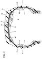
FIG. 2 is a schematic view showing a state where the tire measuring tool ofFIG. 1 is mounted on a tire. -
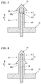
FIG. 3 is a longitudinal sectional view of a tire measuring tool shown as a second embodiment related to the invention. -
FIG. 4 is a longitudinal sectional view of a tire measuring tool shown as a third embodiment related to the invention. -
FIG. 5 is a longitudinal sectional view of a tire measuring tool shown as a fourth embodiment related to the invention. -
FIG. 6 is a longitudinal sectional view of a tire measuring tool shown as a fifth embodiment related to the invention. -
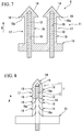
FIG. 7 is a longitudinal sectional view of a tire measuring tool shown as a sixth embodiment related to the invention. -
FIG. 8 is a partially longitudinal sectional view of a tire measuring tool shown as a seventh embodiment related to the invention. -
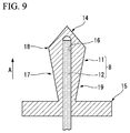
FIG. 9 is a longitudinal sectional view of a tire measuring tool shown as an eighth embodiment related to the invention. - Hereinafter, an embodiment of a tire measuring tool related to the invention will be described, with reference to
FIGS. 1 and2 . - A
tire measuring tool 1 of the present embodiment includes apiercing member 11 that pierces the surface of a tire W, and ameasuring terminal 12 built into thepiercing member 11. Themeasuring tool 1 is used after themeasuring terminal 12 is connected to a mainmeasuring tool body 13 that receives output signals from themeasuring terminal 12. - The
measuring terminal 12 includes sensors, such as a thermocouple, a strain gauge, and an accelerometer, which measure temperature, strain, vibration, displacement, force, and the like, and outputs the acquired data. - In the
piercing member 11, afirst end 14 is formed in a pointed shape with a diameter which is gradually reduced toward the tip thereof. Additionally, asecond end 15 is formed in a flange shape protruding outward in a radial direction. In addition, thepiercing member 11 is integrally formed of, for example, iron, silver, copper, or alloys thereof, or synthetic resin materials. - In the
piercing member 11, anengaging protrusion 18 is provided to protrude from an outer peripheral surface of a first end-side portion 17 that is located closer to thefirst end 14 side than thesecond end 15. Theengaging protrusion 18 is engaged with the portion of the wire W adjacent to theengaging protrusion 18 in a direction opposite to a piercing direction A pointing from thesecond end 15 side toward thefirst end 14 side, in a state where the first end-side portion 17 pierces the surface of the tire W and is buried inside the tire W. - Moreover, in the present embodiment, the
engaging protrusion 18 has anengaging surface 18a that points to the above opposite direction. In the shown example, theengaging protrusion 18 is formed integrally with thefirst end 14 of thepiercing member 11, and is formed in a spindle shape with a diameter which is gradually reduced from thesecond end 15 side toward thefirst end 14 side, and the end surface, on thesecond end 15 side, of this outer surface pointing to the above opposite direction becomes anengaging surface 18a. In addition, an outer peripheral surface of anintermediate portion 19 that is located closer to thesecond end 15 side than the first end - 14 in the first end-
side portion 17 of thepiercing member 11 extends in the piercing direction A parallel thereto. Accordingly, a maximum external diameter portion in the first end-side portion 17 of thepiercing member 11 is a portion where theengaging surface 18a of theengaging protrusion 18 is located. - Additionally, the piercing
member 11 is formed with a mountinghole 16 that opens on thesecond end 15 side and is closed on thefirst end 14 side. The measuringterminal 12 is inserted into and mounted on the mountinghole 16 from the opening on thesecond end side 15 of the piercingmember 11 toward thefirst end 14 side. - Next, a method of measuring the tire W using the
measuring tool 1 configured as above will be described. - First, the piercing
member 11 pierces an inner surface w1 in the surface of the tire W, which defines an internal space X of the tire W, from thefirst end 14 side. - In this case, the implanting interval of steel cords buried inside the tire W becomes equal to or more than the external diameter of a portion where the
engaging surface 18a of the first end-side portion 17 is located. - In addition, if necessary, as shown in
FIG. 2 , a plurality of the piercingmembers 11 separately pierces the tire W in a plurality of places. Additionally, if necessary, by interposing aspacer 21, such as a washer, between thesecond end 15 of the piercingmember 11 and the inner surface w1 of the tire W, the position of the measuringterminal 12 along the piercing direction A within the tire W is adjusted, for example, by lessening the amount of advance of the piercingmember 11 into the tire W. - Then, an entire measuring device including the piercing
member 11, the measuringterminal 12, the mainmeasuring tool body 13, and a wiring line Y connecting the mainmeasuring tool body 13 and the measuringterminal 12 is located in the internal space X of the tire W. In this case, in the shown example, the mainmeasuring tool body 13 is arranged in the portion of the inner surface w1 of the tire W where a tread portion is located. Thereafter, the tire W is mounted on a vehicle together with the measuring device, the mainmeasuring tool body 13 receives the output signals from the measuringterminal 12 while the vehicle is made to travel on a driveway, and the tire W is measured, storing required data serially while processing is performed if necessary. - As described above, according to the
tire measuring tool 1 related to the present embodiment, thefirst end 14 of the piercingmember 11 is formed in the pointed shape. Therefore, for example, even if the outer surface of the tire W is not subjected to drilling or the like, it is possible to advance and bury the first end-side portion 17 into the tire W simply by piercing the surface of the tire W with thefirst end 14 of the piercingmember 11. - Additionally, the engaging
protrusion 18 is provided to protrude from the first end-side portion 17 of the piercingmember 11. Thus, as the engagingprotrusion 18 is engaged with the portion of the tire W adjacent to the engagingprotrusion 18 in the above opposite direction in a state where the first end-side portion 17 pierces the surface of the tire W and is buried within the tire W, it is possible to restrict the movement of the piercingmember 11 in the above opposite direction, and it is possible to prevent the piercingmember 11 from slipping out of the tire W. - Additionally, even if drilling is not performed, it is possible to bury the first end-
side portion 17 of the piercingmember 11 within the tire W. Therefore, the first end-side portion 17 can be easily buried within the tire W not only from the outer surface side of the tire W but from the inner surface w1 side. - Moreover, since the engaging
protrusion 18 has theengaging surface 18a, it is possible to cause the engagingprotrusion 18 to cut toward the inside of the tire W in a direction intersecting the piercing direction A. Therefore, the piercingmember 11 is strongly engaged with the tire W, so that and the piercingmember 11 can be reliably inhibited from slipping out of the tire W. - Additionally, since the mounting
hole 16 is formed in the piercingmember 11, it is possible to select the type of the measuringterminal 12 built into the piercingmember 11, for example, when performing measurement. Otherwise, it is possible to extract only the measuringterminal 12 from the mountinghole 16 with the surface of the tire W being pierced with the piercingmember 11 after the end of measurement, and then to mount another measuringterminal 12 on the mountinghole 16 of the same piercingmember 11. Therefore, handling becomes easier compared to a configuration in which both of the measuringterminal 12 and the piercingmember 11 are integrally formed, for example, by casing or injection-molding the piercingmember 11 using the measuringterminal 12 as an insert article. - Moreover, according to the tire measuring method related to the present embodiment, it is possible to pierce the inner surface w1 of the tire W from the
first end 14 side with the piercingmember 11. In addition, since the tire W is measured in a state where the mainmeasuring tool body 13 is disposed in the internal space X of the tire W, it is possible to locate the entire measuring device including the piercingmember 11, the measuringterminal 12, the mainmeasuring tool body 13, and the aforementioned wiring line Y in the internal space X of the tire W when performing measurement. Therefore, it becomes easy to measure, for example, the tire W that is traveling on a driveway in a state where the measuring device is mounted on a vehicle, and it is also possible to limit the length of the aforementioned wiring line Y That is, installation of this measuring device to the tire W can be easily performed. - Additionally, the implanting interval of steel cords buried inside the wire W to be measured becomes equal to or more than the external diameter of the maximum external diameter portion in the first end-
side portion 17 of the piercingmember 11. Therefore, when the first end-side portion 17 of the piercingmember 11 is advanced into the tire W, it is possible to limit the first end-side portion 17 from hitting the steel cords and this advance is hindered. - Additionally, since the main
measuring tool body 13 is arranged in the portion of the inner surface w1 of the tire W where a tread portion is located, it is possible to limit the mainmeasuring tool body 13 from being separated from the tire W at the time of measurement. - In addition, the technical scope of the invention is not limited to the aforementioned embodiment, and various changes can be made without departing from the concept of the invention.
- For example, a configuration in which the mounting
hole 16 is formed in the piercingmember 11 and the measuringterminal 12 is inserted into the mountinghole 16 has been shown in the above embodiment. Therefore, ameasuring tool 2 may be adopted in which both of the measuringterminal 12 and the piercingmember 11 are integrally formed as shown inFIG. 3 by casing or injection-molding the piercingmember 11 using the measuringterminal 12 as an insert article. - Additionally, as shown in
FIG. 4 , ameasuring tool 3 may be adopted in which the engagingprotrusion 18 having theengaging surface 18a is separated from thefirst end 14 to thesecond end 15 side and is disposed at theintermediate portion 19 of the first end-side portion 17. - Moreover, as shown in
FIG. 5 , ameasuring tool 4 may be adopted in which a plurality of the engagingprotrusions 18 having theengaging surface 18a are continuously provided along the piercing direction A at the first end-side portion 17. - Additionally, as shown in
FIG. 6 , ameasuring tool 5 may be adopted in which the piercingmember 11 is split into a plurality of pieces in the radial direction. - In the shown example, the piercing
member 11 includes aninner cylinder 11 a that is formed with the mountinghole 16 and has the measuringterminal 12 mounted on the mountinghole 16 and anouter cylinder 11b in which theinner cylinder 11a is built. A first end of theinner cylinder 11 a is formed in a pointed shape with a diameter which is gradually reduced toward the tip thereof. An outer peripheral surface of the portion of theinner cylinder 11 a located closer to the second end side than the first end extends in the direction A parallel thereto. The engagingprotrusion 18 having theengaging surface 18a is provided to protrude from the first end of theouter cylinder 11b. The first end of theouter cylinder 11b opens in the piercing direction A, and the first end of theinner cylinder 11 a protrudes in the piercing direction A through this opening. - Moreover, as shown in
FIG. 7 , ameasuring tool 6 may be adopted in which onesecond end 15 and a plurality of the first end-side portions 17 are integrally formed, the mountinghole 16 is formed in each of the first end-side portions 17, and the measuringterminal 12 is mounted on each mountinghole 16. - Additionally, as shown in
FIG. 8 , ameasuring tool 7 may be adopted in which a plurality of the engagingprotrusions 18 are continuously provided along both directions of the piercing direction A and a circumferential direction circling around a central axis of the piercingmember 11 extending in the piercing direction A, and the amount of protrusion of each of the engagingprotrusions 18 toward a radial outer side is made gradually larger from thefirst end 14 side toward thesecond end 15 side. - In the shown example, the length of the engaging
protrusion 18 in the circumferential direction becomes gradually shorter from thefirst end 14 side toward thesecond end 15 side, and the circumferential spacing between the engagingprotrusions 18 adjacent to each other in the circumferential direction becomes gradually larger from thefirst end 14 side toward thesecond end 15 side. The engagingprotrusions 18 allow the first end-side portion 17 to assume a squamate pattern as seen from the radial outer side. - Moreover, as shown in
FIG. 9 , ameasuring tool 8 may be adopted in which theengaging surface 18a is not provided, and the external diameter of theintermediate portion 19 of the first end-side portion 17 is made to have a diameter which is gradually increased from thesecond end 15 side toward thefirst end 14 side. - The piercing
member 11 may pierce the outer surface of the tire W. - Additionally, in the above respective embodiments, the engaging
protrusion 18 is provided in the piercingmember 11. However, the engagingprotrusion 18 may not be provided. - In addition, the constituent elements in the above-described embodiments can be substituted with well-known constituent elements without departing from the scope of the invention. Additionally, the above-described modifications may be appropriately combined.
- The measuring terminal can be easily attached to tires.
-
- 1 TO 8:
- MEASURING TOOL
- 11:
- PIERCING MEMBER
- 12:
- MEASURING TERMINAL
- 13:
- MAIN MEASURING TOOL BODY
- 14:
- FIRST END
- 15:
- SECOND END
- 16:
- MOUNTING HOLE
- 17:
- FIRST END-SIDE PORTION
- 18:
- ENGAGING PROTRUSION
- 18a:
- ENGAGING SURFACE
- A:
- PIERCING DIRECTION
- X:
- INTERNAL SPACE
- W:
- TIRE
- w1:
- INNER SURFACE
Claims (4)
- A tire measuring tool comprising:a piercing member that pierces the surface of a tire; anda measuring terminal built into the piercing member,wherein the measuring tool is used after the measuring terminal is connected to a main measuring tool body that receives an output signal from the measuring terminal, andwherein the piercing member has a first end having a pointed shape with a diameter which is gradually reduced toward the tip thereof, and a second end formed in a flange shape overhanging outward in a radial direction.
- The tire measuring tool according to Claim 1,
wherein the piercing member is formed with a mounting hole that opens on the second end side, is closed on the first end side, and allows the measuring terminal to be inserted thereinto. - A tire measuring method comprising:using the tire measuring tool according to Claim 1;piercing an inner surface of the surface of the tire that defines an internal space of the tire from the first end-side by the piercing member; andmeasuring the tire in a state where the main measuring tool body is disposed in the internal space of the tire.
- The tire measuring method according to Claim 3,
wherein a first end-side portion of the piercing member measures the tire by piercing the surface of the tire in which the implanting interval of steel cords buried inside the tire is equal to or more than the external diameter of a maximum external diameter portion in the first end-side portion located closer to the first end side than the second end.
Applications Claiming Priority (2)
| Application Number | Priority Date | Filing Date | Title |
|---|---|---|---|
| JP2013087586A JP5466777B1 (en) | 2013-04-18 | 2013-04-18 | Tire measuring instrument and tire measuring method |
| PCT/JP2014/060112 WO2014171360A1 (en) | 2013-04-18 | 2014-04-07 | Tire measuring tool and tire measuring method |
Publications (2)
| Publication Number | Publication Date |
|---|---|
| EP2988109A1 true EP2988109A1 (en) | 2016-02-24 |
| EP2988109A4 EP2988109A4 (en) | 2016-03-09 |
Family
ID=50619479
Family Applications (1)
| Application Number | Title | Priority Date | Filing Date |
|---|---|---|---|
| EP14785772.6A Withdrawn EP2988109A4 (en) | 2013-04-18 | 2014-04-07 | Tire measuring tool and tire measuring method |
Country Status (5)
| Country | Link |
|---|---|
| US (1) | US20160076974A1 (en) |
| EP (1) | EP2988109A4 (en) |
| JP (1) | JP5466777B1 (en) |
| CN (1) | CN105122030B (en) |
| WO (1) | WO2014171360A1 (en) |
Cited By (4)
| Publication number | Priority date | Publication date | Assignee | Title |
|---|---|---|---|---|
| FR3120015A1 (en) * | 2021-02-25 | 2022-08-26 | Compagnie Generale Des Etablissements Michelin | Method of instrumenting a tire for measuring the internal temperature while driving |
| EP4010206A4 (en) * | 2019-08-05 | 2023-08-02 | Bridgestone Americas Tire Operations, LLC | Tire electronics assembly |
| EP4010208A4 (en) * | 2019-08-05 | 2023-08-09 | Bridgestone Americas Tire Operations, LLC | Tire electronics assembly |
| US12589619B2 (en) | 2021-02-25 | 2026-03-31 | Compagnie Generale Des Etablissements Michelin | System for measuring the internal temperature of a running tire |
Families Citing this family (3)
| Publication number | Priority date | Publication date | Assignee | Title |
|---|---|---|---|---|
| BR112017013826B1 (en) * | 2014-12-30 | 2021-06-22 | Bridgestone Americas Tire Operations, Llc | TIRE INCLUDING ELECTRONIC DEVICE FIXER |
| JP6507093B2 (en) * | 2015-12-21 | 2019-04-24 | 株式会社ブリヂストン | Rubber member measuring apparatus and measuring method |
| CN111458165A (en) * | 2020-05-28 | 2020-07-28 | 高铁检测仪器(东莞)有限公司 | Testing method of gantry type tire comprehensive strength testing machine |
Family Cites Families (16)
| Publication number | Priority date | Publication date | Assignee | Title |
|---|---|---|---|---|
| FR687236A (en) * | 1930-09-19 | 1930-08-06 | Warning device for monitoring and measuring the air pressure contained in automobile air chambers or the pressure of air or other gases, or fluids, enclosed in any receptacles | |
| GB9903114D0 (en) * | 1999-02-11 | 1999-04-07 | Five Engineers Rooting A Livin | Signal transmission |
| EP1222080B1 (en) * | 1999-10-01 | 2003-07-02 | The Goodyear Tire & Rubber Company | Method for monitoring a condition of a tyre |
| JP2001208618A (en) | 2000-01-27 | 2001-08-03 | Bridgestone Corp | Method and apparatus for measuring internal temperature of tire |
| JP2002264617A (en) * | 2001-03-07 | 2002-09-18 | Hanex Co Ltd | Installation structure of RFID tag on tire |
| US6854324B2 (en) * | 2002-12-20 | 2005-02-15 | The Goodyear Tire & Rubber Company | Tire monitoring apparatus |
| JP2005241438A (en) * | 2004-02-26 | 2005-09-08 | Denso Corp | A tire condition detection device, a tire condition monitoring system, and a method for attaching the tire condition detection device to a tire wheel. |
| US7325448B2 (en) * | 2004-03-02 | 2008-02-05 | Bridgestone Corporation | Pneumatic-tire-use electronic-device fixing system, and electronic-device housing apparatus |
| JPWO2005095127A1 (en) * | 2004-03-31 | 2008-02-21 | 株式会社ブリヂストン | Wireless IC tag mounting holder and tire with wireless IC tag |
| EP1721761A1 (en) * | 2005-05-12 | 2006-11-15 | Société de Technologie Michelin | Method of securing a tire-based unit of a tire condition sensing system to a rim and an associated apparatus |
| JP3933178B1 (en) * | 2005-12-14 | 2007-06-20 | 均 長岩 | Mechanical blind expansion board anchor |
| US20080175689A1 (en) * | 2007-01-22 | 2008-07-24 | Michael Vagedes | Vinyl siding fastener |
| BR112012007178A8 (en) * | 2009-09-30 | 2017-12-26 | Michelin Rech Tech | TIRE TEMPERATURE MEASURING DEVICE, METHOD FOR MEASURING THE TEMPERATURE OF A TIRE |
| FR2962936B1 (en) * | 2010-07-21 | 2012-07-27 | Michelin Soc Tech | METHOD AND DEVICE FOR MONITORING AND / OR ADJUSTING PRESSURE FOR A MONTE ASSEMBLY |
| KR20130030078A (en) * | 2011-09-16 | 2013-03-26 | 삼성전기주식회사 | Tire status monitoring apparatus |
| JP2013104758A (en) * | 2011-11-14 | 2013-05-30 | Sumitomo Rubber Ind Ltd | Tire displacement measurement instrument |
-
2013
- 2013-04-18 JP JP2013087586A patent/JP5466777B1/en not_active Expired - Fee Related
-
2014
- 2014-04-07 CN CN201480021777.4A patent/CN105122030B/en not_active Expired - Fee Related
- 2014-04-07 WO PCT/JP2014/060112 patent/WO2014171360A1/en not_active Ceased
- 2014-04-07 EP EP14785772.6A patent/EP2988109A4/en not_active Withdrawn
- 2014-04-07 US US14/783,657 patent/US20160076974A1/en not_active Abandoned
Cited By (8)
| Publication number | Priority date | Publication date | Assignee | Title |
|---|---|---|---|---|
| EP4010206A4 (en) * | 2019-08-05 | 2023-08-02 | Bridgestone Americas Tire Operations, LLC | Tire electronics assembly |
| EP4010208A4 (en) * | 2019-08-05 | 2023-08-09 | Bridgestone Americas Tire Operations, LLC | Tire electronics assembly |
| US12097729B2 (en) | 2019-08-05 | 2024-09-24 | Bridgestone Americas Tire Operations, Llc | Tire electronics assembly |
| US12636918B2 (en) | 2019-08-05 | 2026-05-26 | Bridgestone Americas Tire Operations, Llc | Tire electronics assembly |
| FR3120015A1 (en) * | 2021-02-25 | 2022-08-26 | Compagnie Generale Des Etablissements Michelin | Method of instrumenting a tire for measuring the internal temperature while driving |
| WO2022180320A1 (en) * | 2021-02-25 | 2022-09-01 | Compagnie Generale Des Etablissements Michelin | Tire instrumentation method for measuring the internal temperature during rolling |
| US12589619B2 (en) | 2021-02-25 | 2026-03-31 | Compagnie Generale Des Etablissements Michelin | System for measuring the internal temperature of a running tire |
| US12638337B2 (en) | 2021-02-25 | 2026-05-26 | Compagnie Generale Des Etablissements Michelin | Tire instrumentation method for measuring the internal temperature during rolling |
Also Published As
| Publication number | Publication date |
|---|---|
| US20160076974A1 (en) | 2016-03-17 |
| WO2014171360A1 (en) | 2014-10-23 |
| CN105122030A (en) | 2015-12-02 |
| JP5466777B1 (en) | 2014-04-09 |
| CN105122030B (en) | 2018-07-27 |
| EP2988109A4 (en) | 2016-03-09 |
| JP2014211355A (en) | 2014-11-13 |
Similar Documents
| Publication | Publication Date | Title |
|---|---|---|
| US20160076974A1 (en) | Tire measuring tool and tire measuring method | |
| Muzyka et al. | Progress and challenges in electrochemiluminescent aptasensors | |
| MX2021009429A (en) | Electronic device with metal frame antenna. | |
| JP2013200032A (en) | Ball screw device | |
| CN110537034B (en) | Combined detection of wear of components of a brake system, in particular of a motor vehicle | |
| GB2546050A (en) | Magnetic sensor rotation and orientation about drill | |
| WO2011100306A3 (en) | Determination of physical connectivity status of devices based on electrical measurement | |
| JP2014159847A (en) | Ball screw bearing device | |
| US9263840B1 (en) | Self-monitoring electrical contact insertion tool | |
| JP6046011B2 (en) | Manhole monitoring system | |
| EP2977624B1 (en) | Identification system with electronic tag for identifying a rolling bearing and hub bearing unit equipped therewith | |
| US20160215610A1 (en) | Bend measurements of adjustable motor assemblies using magnetometers | |
| MA50863A (en) | DEVICE, CHARGE COLUMN AS WELL AS A METHOD FOR DETECTION OF THE STATE OF A MOTOR VEHICLE BATTERY | |
| US20150128704A1 (en) | Arrangement for monitoring a structural component which rotates about its axis | |
| JP6027305B2 (en) | Pneumatic tire | |
| CN204615126U (en) | A kind of wire harness, the transducer with this wire harness and device | |
| US20160146256A1 (en) | Instrumented bearing and method of manufacturing such an instrumented bearing | |
| EP2787586A1 (en) | Installation assembly for bridging a cable harness or the like between two aircraft structure elements | |
| MX2018010274A (en) | COIL. | |
| EP3649702B1 (en) | Covering element for an alternator pole | |
| EP2916632A1 (en) | Apparatus for mounting a printed circuit board | |
| US9696334B2 (en) | Wheel speed sensor | |
| KR20190054319A (en) | Cable laid grommet | |
| BR112017019427A2 (en) | tubular wellbore bottom structure | |
| FR3016557B1 (en) | SYSTEM FOR DETECTION OF A LOCKING WAITING POSITION OF A MOTOR VEHICLE LOCKING ELEMENT |
Legal Events
| Date | Code | Title | Description |
|---|---|---|---|
| PUAI | Public reference made under article 153(3) epc to a published international application that has entered the european phase |
Free format text: ORIGINAL CODE: 0009012 |
|
| 17P | Request for examination filed |
Effective date: 20151013 |
|
| AK | Designated contracting states |
Kind code of ref document: A1 Designated state(s): AL AT BE BG CH CY CZ DE DK EE ES FI FR GB GR HR HU IE IS IT LI LT LU LV MC MK MT NL NO PL PT RO RS SE SI SK SM TR |
|
| AX | Request for extension of the european patent |
Extension state: BA ME |
|
| A4 | Supplementary search report drawn up and despatched |
Effective date: 20160210 |
|
| RIC1 | Information provided on ipc code assigned before grant |
Ipc: B60C 23/20 20060101ALI20160204BHEP Ipc: B60C 19/00 20060101ALI20160204BHEP Ipc: B60C 23/04 20060101ALI20160204BHEP Ipc: G01M 17/02 20060101AFI20160204BHEP |
|
| DAX | Request for extension of the european patent (deleted) | ||
| 17Q | First examination report despatched |
Effective date: 20160930 |
|
| STAA | Information on the status of an ep patent application or granted ep patent |
Free format text: STATUS: THE APPLICATION IS DEEMED TO BE WITHDRAWN |
|
| 18D | Application deemed to be withdrawn |
Effective date: 20170211 |