EP2988060A1 - Lamp for a vehicle - Google Patents
Lamp for a vehicle Download PDFInfo
- Publication number
- EP2988060A1 EP2988060A1 EP14785414.5A EP14785414A EP2988060A1 EP 2988060 A1 EP2988060 A1 EP 2988060A1 EP 14785414 A EP14785414 A EP 14785414A EP 2988060 A1 EP2988060 A1 EP 2988060A1
- Authority
- EP
- European Patent Office
- Prior art keywords
- light
- reflected
- lights
- incident
- lamp
- Prior art date
- Legal status (The legal status is an assumption and is not a legal conclusion. Google has not performed a legal analysis and makes no representation as to the accuracy of the status listed.)
- Granted
Links
- 238000005286 illumination Methods 0.000 claims description 31
- 241000258971 Brachiopoda Species 0.000 claims description 8
- 238000010586 diagram Methods 0.000 description 3
- 206010047571 Visual impairment Diseases 0.000 description 2
- 230000004075 alteration Effects 0.000 description 1
- 230000008901 benefit Effects 0.000 description 1
- 230000008859 change Effects 0.000 description 1
- 230000003247 decreasing effect Effects 0.000 description 1
- 230000006872 improvement Effects 0.000 description 1
- 230000007246 mechanism Effects 0.000 description 1
- 230000004048 modification Effects 0.000 description 1
- 238000012986 modification Methods 0.000 description 1
- 239000004065 semiconductor Substances 0.000 description 1
- 230000003245 working effect Effects 0.000 description 1
Images







Classifications
-
- G—PHYSICS
- G02—OPTICS
- G02B—OPTICAL ELEMENTS, SYSTEMS OR APPARATUS
- G02B26/00—Optical devices or arrangements for the control of light using movable or deformable optical elements
- G02B26/08—Optical devices or arrangements for the control of light using movable or deformable optical elements for controlling the direction of light
- G02B26/10—Scanning systems
- G02B26/12—Scanning systems using multifaceted mirrors
-
- F—MECHANICAL ENGINEERING; LIGHTING; HEATING; WEAPONS; BLASTING
- F21—LIGHTING
- F21S—NON-PORTABLE LIGHTING DEVICES; SYSTEMS THEREOF; VEHICLE LIGHTING DEVICES SPECIALLY ADAPTED FOR VEHICLE EXTERIORS
- F21S41/00—Illuminating devices specially adapted for vehicle exteriors, e.g. headlamps
- F21S41/10—Illuminating devices specially adapted for vehicle exteriors, e.g. headlamps characterised by the light source
- F21S41/14—Illuminating devices specially adapted for vehicle exteriors, e.g. headlamps characterised by the light source characterised by the type of light source
- F21S41/141—Light emitting diodes [LED]
- F21S41/147—Light emitting diodes [LED] the main emission direction of the LED being angled to the optical axis of the illuminating device
- F21S41/148—Light emitting diodes [LED] the main emission direction of the LED being angled to the optical axis of the illuminating device the main emission direction of the LED being perpendicular to the optical axis
-
- F—MECHANICAL ENGINEERING; LIGHTING; HEATING; WEAPONS; BLASTING
- F21—LIGHTING
- F21S—NON-PORTABLE LIGHTING DEVICES; SYSTEMS THEREOF; VEHICLE LIGHTING DEVICES SPECIALLY ADAPTED FOR VEHICLE EXTERIORS
- F21S41/00—Illuminating devices specially adapted for vehicle exteriors, e.g. headlamps
- F21S41/10—Illuminating devices specially adapted for vehicle exteriors, e.g. headlamps characterised by the light source
- F21S41/14—Illuminating devices specially adapted for vehicle exteriors, e.g. headlamps characterised by the light source characterised by the type of light source
- F21S41/16—Laser light sources
-
- F—MECHANICAL ENGINEERING; LIGHTING; HEATING; WEAPONS; BLASTING
- F21—LIGHTING
- F21S—NON-PORTABLE LIGHTING DEVICES; SYSTEMS THEREOF; VEHICLE LIGHTING DEVICES SPECIALLY ADAPTED FOR VEHICLE EXTERIORS
- F21S41/00—Illuminating devices specially adapted for vehicle exteriors, e.g. headlamps
- F21S41/30—Illuminating devices specially adapted for vehicle exteriors, e.g. headlamps characterised by reflectors
- F21S41/32—Optical layout thereof
- F21S41/321—Optical layout thereof the reflector being a surface of revolution or a planar surface, e.g. truncated
-
- F—MECHANICAL ENGINEERING; LIGHTING; HEATING; WEAPONS; BLASTING
- F21—LIGHTING
- F21S—NON-PORTABLE LIGHTING DEVICES; SYSTEMS THEREOF; VEHICLE LIGHTING DEVICES SPECIALLY ADAPTED FOR VEHICLE EXTERIORS
- F21S41/00—Illuminating devices specially adapted for vehicle exteriors, e.g. headlamps
- F21S41/30—Illuminating devices specially adapted for vehicle exteriors, e.g. headlamps characterised by reflectors
- F21S41/32—Optical layout thereof
- F21S41/33—Multi-surface reflectors, e.g. reflectors with facets or reflectors with portions of different curvature
- F21S41/334—Multi-surface reflectors, e.g. reflectors with facets or reflectors with portions of different curvature the reflector consisting of patch like sectors
- F21S41/336—Multi-surface reflectors, e.g. reflectors with facets or reflectors with portions of different curvature the reflector consisting of patch like sectors with discontinuity at the junction between adjacent areas
-
- F—MECHANICAL ENGINEERING; LIGHTING; HEATING; WEAPONS; BLASTING
- F21—LIGHTING
- F21S—NON-PORTABLE LIGHTING DEVICES; SYSTEMS THEREOF; VEHICLE LIGHTING DEVICES SPECIALLY ADAPTED FOR VEHICLE EXTERIORS
- F21S41/00—Illuminating devices specially adapted for vehicle exteriors, e.g. headlamps
- F21S41/30—Illuminating devices specially adapted for vehicle exteriors, e.g. headlamps characterised by reflectors
- F21S41/32—Optical layout thereof
- F21S41/36—Combinations of two or more separate reflectors
- F21S41/365—Combinations of two or more separate reflectors successively reflecting the light
-
- F—MECHANICAL ENGINEERING; LIGHTING; HEATING; WEAPONS; BLASTING
- F21—LIGHTING
- F21S—NON-PORTABLE LIGHTING DEVICES; SYSTEMS THEREOF; VEHICLE LIGHTING DEVICES SPECIALLY ADAPTED FOR VEHICLE EXTERIORS
- F21S41/00—Illuminating devices specially adapted for vehicle exteriors, e.g. headlamps
- F21S41/30—Illuminating devices specially adapted for vehicle exteriors, e.g. headlamps characterised by reflectors
- F21S41/39—Attachment thereof
-
- F—MECHANICAL ENGINEERING; LIGHTING; HEATING; WEAPONS; BLASTING
- F21—LIGHTING
- F21S—NON-PORTABLE LIGHTING DEVICES; SYSTEMS THEREOF; VEHICLE LIGHTING DEVICES SPECIALLY ADAPTED FOR VEHICLE EXTERIORS
- F21S41/00—Illuminating devices specially adapted for vehicle exteriors, e.g. headlamps
- F21S41/60—Illuminating devices specially adapted for vehicle exteriors, e.g. headlamps characterised by a variable light distribution
- F21S41/65—Illuminating devices specially adapted for vehicle exteriors, e.g. headlamps characterised by a variable light distribution by acting on light sources
- F21S41/663—Illuminating devices specially adapted for vehicle exteriors, e.g. headlamps characterised by a variable light distribution by acting on light sources by switching light sources
-
- F—MECHANICAL ENGINEERING; LIGHTING; HEATING; WEAPONS; BLASTING
- F21—LIGHTING
- F21S—NON-PORTABLE LIGHTING DEVICES; SYSTEMS THEREOF; VEHICLE LIGHTING DEVICES SPECIALLY ADAPTED FOR VEHICLE EXTERIORS
- F21S41/00—Illuminating devices specially adapted for vehicle exteriors, e.g. headlamps
- F21S41/60—Illuminating devices specially adapted for vehicle exteriors, e.g. headlamps characterised by a variable light distribution
- F21S41/67—Illuminating devices specially adapted for vehicle exteriors, e.g. headlamps characterised by a variable light distribution by acting on reflectors
- F21S41/675—Illuminating devices specially adapted for vehicle exteriors, e.g. headlamps characterised by a variable light distribution by acting on reflectors by moving reflectors
-
- F—MECHANICAL ENGINEERING; LIGHTING; HEATING; WEAPONS; BLASTING
- F21—LIGHTING
- F21S—NON-PORTABLE LIGHTING DEVICES; SYSTEMS THEREOF; VEHICLE LIGHTING DEVICES SPECIALLY ADAPTED FOR VEHICLE EXTERIORS
- F21S43/00—Signalling devices specially adapted for vehicle exteriors, e.g. brake lamps, direction indicator lights or reversing lights
- F21S43/10—Signalling devices specially adapted for vehicle exteriors, e.g. brake lamps, direction indicator lights or reversing lights characterised by the light source
- F21S43/13—Signalling devices specially adapted for vehicle exteriors, e.g. brake lamps, direction indicator lights or reversing lights characterised by the light source characterised by the type of light source
-
- F—MECHANICAL ENGINEERING; LIGHTING; HEATING; WEAPONS; BLASTING
- F21—LIGHTING
- F21S—NON-PORTABLE LIGHTING DEVICES; SYSTEMS THEREOF; VEHICLE LIGHTING DEVICES SPECIALLY ADAPTED FOR VEHICLE EXTERIORS
- F21S43/00—Signalling devices specially adapted for vehicle exteriors, e.g. brake lamps, direction indicator lights or reversing lights
- F21S43/10—Signalling devices specially adapted for vehicle exteriors, e.g. brake lamps, direction indicator lights or reversing lights characterised by the light source
- F21S43/13—Signalling devices specially adapted for vehicle exteriors, e.g. brake lamps, direction indicator lights or reversing lights characterised by the light source characterised by the type of light source
- F21S43/14—Light emitting diodes [LED]
-
- F—MECHANICAL ENGINEERING; LIGHTING; HEATING; WEAPONS; BLASTING
- F21—LIGHTING
- F21S—NON-PORTABLE LIGHTING DEVICES; SYSTEMS THEREOF; VEHICLE LIGHTING DEVICES SPECIALLY ADAPTED FOR VEHICLE EXTERIORS
- F21S43/00—Signalling devices specially adapted for vehicle exteriors, e.g. brake lamps, direction indicator lights or reversing lights
- F21S43/30—Signalling devices specially adapted for vehicle exteriors, e.g. brake lamps, direction indicator lights or reversing lights characterised by reflectors
- F21S43/31—Optical layout thereof
-
- F—MECHANICAL ENGINEERING; LIGHTING; HEATING; WEAPONS; BLASTING
- F21—LIGHTING
- F21S—NON-PORTABLE LIGHTING DEVICES; SYSTEMS THEREOF; VEHICLE LIGHTING DEVICES SPECIALLY ADAPTED FOR VEHICLE EXTERIORS
- F21S43/00—Signalling devices specially adapted for vehicle exteriors, e.g. brake lamps, direction indicator lights or reversing lights
- F21S43/30—Signalling devices specially adapted for vehicle exteriors, e.g. brake lamps, direction indicator lights or reversing lights characterised by reflectors
- F21S43/37—Attachment thereof
-
- B—PERFORMING OPERATIONS; TRANSPORTING
- B60—VEHICLES IN GENERAL
- B60Q—ARRANGEMENT OF SIGNALLING OR LIGHTING DEVICES, THE MOUNTING OR SUPPORTING THEREOF OR CIRCUITS THEREFOR, FOR VEHICLES IN GENERAL
- B60Q2400/00—Special features or arrangements of exterior signal lamps for vehicles
- B60Q2400/50—Projected symbol or information, e.g. onto the road or car body
-
- F—MECHANICAL ENGINEERING; LIGHTING; HEATING; WEAPONS; BLASTING
- F21—LIGHTING
- F21W—INDEXING SCHEME ASSOCIATED WITH SUBCLASSES F21K, F21L, F21S and F21V, RELATING TO USES OR APPLICATIONS OF LIGHTING DEVICES OR SYSTEMS
- F21W2102/00—Exterior vehicle lighting devices for illuminating purposes
- F21W2102/10—Arrangement or contour of the emitted light
- F21W2102/17—Arrangement or contour of the emitted light for regions other than high beam or low beam
- F21W2102/18—Arrangement or contour of the emitted light for regions other than high beam or low beam for overhead signs
Definitions
- the light control member controls the lights incident thereon so as to be collected below a horizontal line in a shining direction.
- a vehicle lamp I includes a first lamp unit 2, a second lamp unit 100 and a third lamp unit 200 (refer to Figs. 1 and 2 ).
- the first lamp unit 2 is provided as, for example, a drawing lamp unit.
- the second lamp unit 100 is provided as, for example, a high beam lamp unit.
- the third lamp unit 200 is provided as, for example, a low beam limp unit.
- the first lamp unit 2 may be provided as a low beam lamp unit.
- the first lam unit 2 may also be provided to function as both a drawing lamp unit and a high beam lamp unit, and as this occurs, either the second lamp unit 100 or the third lamp unit 200 is not provided.
- An outer circumferential surface of the rotary reflector 8 is formed into a first reflecting surface 8a, a second reflecting surface 8b, a third reflecting surface 8c, a fourth reflecting surface 8d, a fifth reflecting surface 8e, and a sixth reflecting surface 8f.
- the individual reflecting surfaces of the rotary reflector 8 reflect light emitted from the light source 7 in predetermined directions.
- the reflecting surfaces 8a, 8b, 8c, 8d, 8e, 8f are inclined at different angles relative to the rotating axis A (refer to Figs. 4 to 9 ), An inclined angle of the first reflecting surface 8a relative to the rotating axis A is set the smallest. An inclined angel of the sixth reflecting surface 8f relative to the rotating axis A is set the greatest. Inclined angles of the second reflecting surface 8b, the third reflecting surface 8c, the fourth reflecting surface 8d and the fifth reflecting surface 8e relative to the rotating axis A are set greater sequentially in that order.
- the light control member 9 is disposed ahead of or behind the light source 7 and below the rotary reflector 8. In the following description, the light control member 9 will be described as being disposed ahead of the light source 7.
- Light reflected on the fourth reflecting surface 8d is incident on the fourth control area 10d as a reflected light E4 and is then reflected on the fourth control area 10d to be shone to the front as an illumination light R4 (refer to Fig. 7 ).
- Light reflected on the fifth reflecting surface 8e is incident on the fifth control area l0e as a reflected light E5 and is then reflected on the fifth control area 10e to be shone to the front as an illumination light R5 (refer to Fig. 8 ).
- Light reflected on the sixth reflecting surface 8f is incident on the sixth control area 10f as a reflected light E6 and is then reflected on the sixth control area 10f to be shone to the front as an illumination light R6 (refer to Fig. 9 ).
- a figure, symbol or character can be drawn in the shining direction of the lights as a result of the light source 7 being turned on and off according to the rotating position of the rotary reflector 8. Consequently, a driver of an on-coming vehicle or a pedestrian can be warned, thereby making it possible to realize an improvement in safety when the vehicle is running.
- the number of reflecting surfaces on the rotary reflector 8 is small, the number of connecting portions (corner portions) between the reflecting surfaces of the rotary reflector 8 is decreased, and therefore, the loss of light emitted from the light source 7 and reflected by the rotary reflector 8 becomes small. This can enhance the shining efficiency of light to the illumination area X, and a circumferential resolution can also be enhanced. Consequently, the number of reflecting surfaces to be formed on the rotary reflector 8 may be determined as required depending upon the required illumination range and resolution, as well as the application of the lamp unit.
Landscapes
- Engineering & Computer Science (AREA)
- General Engineering & Computer Science (AREA)
- Physics & Mathematics (AREA)
- Optics & Photonics (AREA)
- Microelectronics & Electronic Packaging (AREA)
- General Physics & Mathematics (AREA)
- Lighting Device Outwards From Vehicle And Optical Signal (AREA)
- Non-Portable Lighting Devices Or Systems Thereof (AREA)
- Arrangements Of Lighting Devices For Vehicle Interiors, Mounting And Supporting Thereof, Circuits Therefore (AREA)
Abstract
Description
- The present invention relates to a technical field relating to a vehicle lamp having a rotary reflector which has a reflecting surface formed thereon and a light control member which controls light reflected by the rotary reflector.
- In vehicle lamps, there is, for example, a vehicle lamp in which a lamp unit having a light source is disposed in an interior of a lamp shell which is defined by a cover and a lamp housing.
- In lamp units of this type, there is a lamp unit having a configuration in which light emitted from a light source is reflected by a rotary reflector. As such a configuration, there is, for example, a configuration in which a polygonal wheel mirror is provided as a rotary reflector which can rotate about a rotating axis as a fulcrum and which has a plurality of mirror surfaces (reflecting surfaces) (refer to
Patent Literature 1 bellow, for example). - In a vehicle lamp described in
Patent Literature 1, light emitted from a light source is shone on to the mirror surfaces as a polygonal wheel mirror rotates. This can change the shining direction and range of the light which is reflected on the mirror surfaces. - Patent Literature 1:
JP-W-2008-539537 - In the vehicle lamp described in
Patent Literature 1, however, the plurality of reflecting surfaces which reflect light are formed parallel to the rotating axis. Because of this, the shining direction and range of the light which is reflected when the rotary reflector rotates are limited, causing a problem that the degree of freedom in setting the shining direction and range is low. - Then, an object of the invention is to improve the degree of freedom in setting the shining direction and range of light which is reflected by a rotary reflector.
- According to a first aspect of the invention, there is provided a vehicle lamp in which a lamp unit is provided in an interior of a lamp shell which is defined by a cover and a lamp housing, characterized in that the lamp unit comprises a light source which emits light, a rotary reflector which is rotated about a rotating axis as a fulcrum and which has a plurality of reflecting surfaces which reflect light emitted from the light source, and a light control member on which lights reflected on the plurality of reflecting surfaces are incident and which controls the incident lights, and characterized in that angles at which the plurality of reflecting surfaces are inclined relative to the rotating axis are different from one another so that an incident position where the reflected lights are incident on the light control member changes according to a rotating position of the rotary reflector.
- This allows the respective lights reflected on the reflecting surfaces of the rotary reflector to be incident on the light control member in different positions.
- According to a second aspect of the invention, in the vehicle lamp of the invention, it is desirable that the light source is turned on and off or varies its brightness according to a rotating position of the rotary reflector.
- This causes the light to be shone intermittently.
- According to a third aspect of the invention, in the vehicle lamp of the invention, it is desirable that the light control member is a fixed reflector.
- This enables the lights reflected by the rotary reflector to be controlled by the fixed reflector.
- According to a fourth aspect of the invention, in the vehicle lamp of the invention, it is desirable that the light control member controls the lights incident thereon so as to be collected below a horizontal line in a shining direction.
- This enables the lights to be shone downwards below the horizontal line.
- According to a fifth aspect of the invention, in the vehicle lamp of the invention, it is desirable that the lights which are reflected on the reflecting surfaces and are then controlled by the light control member so as to be shone on to an illumination area are each shone into a straight line for each reflecting surface in the illumination area.
- This enables the lights which are straight in shape to be shone on to the illumination area in different shining positions.
- According to the invention, the reflecting surfaces of the rotary reflector are inclined at the different angles relative to the rotating axis thereof, so that the incident position of the reflected lights are incident on the light control member changes according to the rotating position of the rotary reflector. Because of this, when the rotary reflector is rotated, the shining direction and range of the lights shone when the rotary reflector is rotated are not limited, thereby making it possible to improve the degree of freedom relating to the shining direction and range of the lights which are reflected by the rotary reflector to be shone.
-
-
Fig. 1 shows an embodiment of a vehicle lamp of the invention and is a schematic front view of the vehicle lamp. -
Fig. 2 is a schematic vertical sectional view of the vehicle lamp. -
Fig. 3 is a perspective view of a lamp unit. -
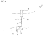
Fig. 4 is a schematic side view showing, partially in section, a path of light reflected by a first reflecting surface. -
Fig. 5 is a schematic side view showing, partially in section, a path of light reflected by a second reflecting surface. -
Fig. 6 is a schematic side view showing, partially in section, a path of light reflected by a third reflecting surface. -
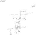
Fig. 7 is a schematic side view showing, partially in section, a path of light reflected by a fourth reflecting surface. -
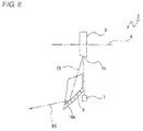
Fig. 8 is a schematic side view showing, partially in section, a path of light reflected by a fifth reflecting surface. -
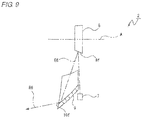
Fig. 9 is a schematic side view showing, partially in section, a path of light reflected by a sixth reflecting surface. -
Fig. 10 is a schematic front view showing a path of light when the first reflecting surface is inclined rightwards. -
Fig. 11 is a schematic front view showing a path of light when the first reflecting surface is directed downwards. -
Fig. 12 is a schematic front view showing a path of light when the first reflecting surface is inclined leftwards. -
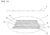
Fig. 13 is a schematic diagram showing lights shone on to an illumination area when a light source is turned on. -
Fig. 14 is a schematic diagram showing lights shone on to the illumination area when the light source is turned on and off. -
Fig. 15 is a schematic diagram showing lights shone on to the illumination area when timings at which the light source is turned on and off are controlled. - Hereinafter, referring to the accompanying drawings, an example of a mode for carrying out a vehicle lamp of the invention will be described.
- A vehicle lamp I includes a
first lamp unit 2, asecond lamp unit 100 and a third lamp unit 200 (refer toFigs. 1 and2 ). Thefirst lamp unit 2 is provided as, for example, a drawing lamp unit. Thesecond lamp unit 100 is provided as, for example, a high beam lamp unit. Thethird lamp unit 200 is provided as, for example, a low beam limp unit. In thevehicle lamp 1, thefirst lamp unit 2 may be provided as a low beam lamp unit. Additionally, thefirst lam unit 2 may also be provided to function as both a drawing lamp unit and a high beam lamp unit, and as this occurs, either thesecond lamp unit 100 or thethird lamp unit 200 is not provided. - The vehicle lamp I has a
lamp shell 5 which is defined by a lamp body 3 (an example of a lamp housing) which is opened in one direction and acover 4 which is attached to an open end portion of thelamp body 3. An interior of thelamp shell 5 is formed as alamp compartment 6. Thefirst lamp unit 2, thesecond lamp unit 100 and thethird lamp unit 200 are disposed in thelamp compartment 6 so as to be spaced apart from one another in a left-to-right direction. - The
first lamp unit 2, thesecond lamp unit 100 and thethird lamp unit 200 are supported by members, not shown, in the interior of thelamp shell 5. - The
first lamp unit 2 has alight source 7, arotary reflector 8 and a light control member 9 (refer toFigs. 2 and3 ). Thelight source 7, therotary reflector 8 and thelight control member 9 are supported by members, not shown, in the interior of thelamp shell 5. - For example, a semiconductor laser (LD: Laser Diode) or a light emitting diode (LED: Light Emitting Diode) is used for the
light source 7, Thelight source 7 emits light upwards towards therotary reflector 8 and is turned on and off according to a rotating operation of therotary reflector 8. - The
rotary reflector 8 is disposed above thelight source 7. Therotary reflector 8 is made up of, for example, a thin, substantially hexagonal plate-like member. Therotary reflector 8 is disposed so that its thickness direction corresponds to a front-to-rear direction and is rotated about a rotating axis A which extends in the front-to-rear direction as a fulcrum by a rotational drive mechanism, not shown. - An outer circumferential surface of the
rotary reflector 8 is formed into a first reflectingsurface 8a, a second reflectingsurface 8b, a third reflectingsurface 8c, a fourth reflectingsurface 8d, a fifth reflectingsurface 8e, and a sixth reflectingsurface 8f. The individual reflecting surfaces of therotary reflector 8 reflect light emitted from thelight source 7 in predetermined directions. - The reflecting
surfaces - The reflecting
surfaces Figs. 4 to 9 ), An inclined angle of the first reflectingsurface 8a relative to the rotating axis A is set the smallest. An inclined angel of the sixth reflectingsurface 8f relative to the rotating axis A is set the greatest. Inclined angles of the second reflectingsurface 8b, the third reflectingsurface 8c, the fourth reflectingsurface 8d and the fifth reflectingsurface 8e relative to the rotating axis A are set greater sequentially in that order. - Light emitted from the
light source 7 is reflected on anyone of the reflectingsurfaces rotary reflector 8. Respective lights reflected on the reflectingsurfaces light control member 9. - The
light control member 9 is disposed ahead of or behind thelight source 7 and below therotary reflector 8. In the following description, thelight control member 9 will be described as being disposed ahead of thelight source 7. - The
light control member 9 has a surface which is directed obliquely upwards, and this surface is formed as a control surface 10 (refer toFig. 3 ). Thelight control member 9 controls light which is reflected by therotary reflector 8 so that a range of an angle at which the reflected light is emitted in a circumferential direction of therotary reflector 8 is narrowed. - The
control surface 10 has six horizontally elongated areas which are formed sequentially from an upper side thereof. These six areas are formed sequentially as afirst control area 10a, asecond control area 10b, athird control area 10c, afourth control area 10d, afifth control area 10e, and asixth control area 10f on thecontrol surface 10. Broken lines are given to thecontrol surface 10 shown inFig. 3 as a matter of convenience to ease the understanding of the positions of thecontrol areas - In the
first lamp unit 2 configured in the way described above, when light is emitted from thelight source 7, the light so emitted is reflected by anyone of the reflectingsurfaces Figs. 3 to 9 ). Lights reflected on the reflectingsurfaces control areas control surface 10 and are then reflected individually on thecontrol areas - Specifically, light reflected on the first reflecting
surface 8a is incident on thecontrol area 10a as a reflected light E1 and is then reflected on thefirst control area 10a to be shone to the front as an illumination light R1 (refer toFigs. 3 and4 ). Light reflected on the second reflectingsurface 8b is incident on thesecond control area 10b as a reflected light E2 and is then reflected on thesecond control area 10b to be shone to the front as an illumination light R2 (refer toFig. 5 ). Light reflected on the third reflectingsurface 8c is incident on thethird control area 10c as a reflected light E3 and is then reflected on thethird control area 10c to be shone to the front as an illumination light R3 (refer toFig. 6 ), Light reflected on the fourth reflectingsurface 8d is incident on thefourth control area 10d as a reflected light E4 and is then reflected on thefourth control area 10d to be shone to the front as an illumination light R4 (refer toFig. 7 ). Light reflected on the fifth reflectingsurface 8e is incident on the fifth control area l0e as a reflected light E5 and is then reflected on thefifth control area 10e to be shone to the front as an illumination light R5 (refer toFig. 8 ). Light reflected on thesixth reflecting surface 8f is incident on thesixth control area 10f as a reflected light E6 and is then reflected on thesixth control area 10f to be shone to the front as an illumination light R6 (refer toFig. 9 ). - As has been described above, when light is emitted from the
light source 7 to therotary reflector 8, since therotary reflector 8 is rotating about the rotating axis A as a fulcrum, respective orientations of the reflectingsurfaces light source 7 are changed gradually. Consequently, lights incident on the reflectingsurfaces control areas control areas Figs. 10 to 12 ). - For example, when the first reflecting
surface 8a is inclined rightwards, the reflected light E1 is incident on a rightward portion of thefirst control area 10a (refer toFig. 10 ). When the first reflectingsurface 8a is oriented downwards without being inclined, the reflected light E1 is incident on a central portion of thefirst control area 10a in a left-to-right direction (refer toFig. 11 ). When the first reflectingsurface 8a is inclined leftwards, the reflected light E1 is incident on a leftward portion of thefirst control area 10a (refer toFig. 12 ). - Although not shown, this will be true with the reflected lights E2, E3, E4, E5, E6 which are reflected on the reflecting
surfaces surfaces control areas - The illumination lights R1, R2, R3, R4, R5, R6 are shone substantially parallel to one another to the front and are controlled by the
light control member 9 so as to be collected to an illumination area X which is situated, for example, below a horizontal line H in the shining direction (forward) (refer toFigs. 13 to 15 ). - Horizontal lines S1, S2, S3, S4, S5, S6 shown in
Fig. 13 show a state in which the illumination lights R1, R2, R3, R4, R5, R6 are shone sequentially in that order when therotary reflector 8 is rotated a full rotation from the first reflectingsurface 8a to thesixth reflecting surface 8f in such a state that light is emitted from thelight source 7. - In the
vehicle lamp 1, therotary reflector 8 rotates continuously at high speeds, and the lights like scanning lines described above are shone on to the illumination area X continuously and repeatedly in an extremely short length of time. Because of this, the lights like scanning lines which are shone on to the illumination area X are visualized as afterimages, resulting in a state in which a certain quantity of light is shone continuously to the illumination area X in a pseudo fashion. When therotary reflector 8 is rotated at high speeds in such a state that thelight source 7 is turned on, thefirst light unit 2 is used as a low beam lamp unit or a high beam lamp unit. When thelight source 7 is turned on, thefirst lamp unit 2 may be used as various sign lamps including a stop lamp, a tail lamp and a cornering lamp. - On the other hand, when the
rotary reflector 8 is rotated a full rotation from the first reflectingsurface 8a to thesixth reflecting surface 8f in such a state that thelight source 7 is turned on and off, a plurality of dot-like lights are shone on to the illumination area X intermittently (refer toFig. 14 ). Horizontal lines S1, S2, S3, S4, S5, S6 (refer to six frames of dotted lines inFig. 14 ) which are each a collection of a plurality of dot-like lights shown inFig. 14 show a state in which the illumination lights R1, R2, R3, R4, R5, R6 are shone sequentially in that order. - In the
vehicle lamp 1, therotary reflector 8 is rotated continuously at high speeds in such a state that thelight source 7 is controlled to be turned on and off according to a rotating position of therotary reflector 8, and the plurality of dot-like lights described above are shone on to the illumination area X in an extremely short length of time. Because of this, as shown inFig. 15 , a collection of those dot-like lights which are shone on to the illumination area X at an arbitrary timing is visualized as an afterimage of a predetermined figure, symbol or a character like an arrow P, for example. In this way, when therotary reflector 8 is rotated at high speeds in such a state that the timings at which thelight source 7 is turned on and off are controlled, thefirst lamp unit 2 is used as a drawing lamp unit which indicates a figure, symbol or character. These figures, symbols or characters are visualized by a driver of a vehicle or a pedestrian as a sign. - Thus, as has been described heretofore, in the
vehicle lamp 1, the angles at which the first reflectingsurface 8a, the second reflectingsurface 8b, the third reflectingsurface 8c, the fourth reflectingsurface 8d, the fifth reflectingsurface 8e, and the sixth reflectingsurface 8f are inclined relative to the rotating axis A are different, and the positions of the reflected lights E (EI to E6) which are incident on thelight control member 9 are changed according to the rotating position of therotary reflector 8. - Consequently, the shining range and direction of the reflected lights E (El to E6) are not limited when the
rotary reflector 8 is rotated which reflects the light emitted from thelight source 7, thereby making it possible to improve the degree of freedom relating to the direction and range of the light which is reflected on therotary reflector 8. - In addition, in the
vehicle lamp 1, a figure, symbol or character can be drawn in the shining direction of the lights as a result of thelight source 7 being turned on and off according to the rotating position of therotary reflector 8. Consequently, a driver of an on-coming vehicle or a pedestrian can be warned, thereby making it possible to realize an improvement in safety when the vehicle is running. - Further, in the
vehicle lamp 1, the control of the light can be eased by the simple configuration by using a fixed reflector as thelight control member 9. Thelight control member 9 may be a lens member which reflects light internally. Even in the event that such a lens member is used as thelight control member 9, too, the same working effect can be provided as that provided when the fixed reflector is used. - Furthermore, as has been described above, the reflected lights E (EI to E6) which are incident on the
light control member 9 are shone therefrom so as to be collected below the horizontal line H as the illumination lights R (R1 to R6). This can prevent drivers of a preceding vehicle and an on-coming vehicle from being dazzled in such a state that the lights are shone on to the range required by the application. - Additionally, in the
vehicle lamp 1, the lights reflected on the reflectingsurfaces light control member 9 so as to be shone on to the illumination area X are formed into the straight lines which correspond individually to the reflectingsurfaces - In the embodiment described above, while the
rotary reflector 8 is described as having the six reflectingsurfaces rotary reflector 8, is expanded. On the other hand, in case the number of reflecting surfaces is great, the angle at which the reflected light is emitted in the circumferential direction of therotary reflector 8, is narrowed. However, the size of the illumination area X can be controlled by the use of thelight control member 9. - In addition, in case the number of reflecting surfaces on the
rotary reflector 8 is small, the number of connecting portions (corner portions) between the reflecting surfaces of therotary reflector 8 is decreased, and therefore, the loss of light emitted from thelight source 7 and reflected by therotary reflector 8 becomes small. This can enhance the shining efficiency of light to the illumination area X, and a circumferential resolution can also be enhanced. Consequently, the number of reflecting surfaces to be formed on therotary reflector 8 may be determined as required depending upon the required illumination range and resolution, as well as the application of the lamp unit. - In the embodiment described above, while the
light source 7 is described as being turned on or off according to the rotating position of therotary reflector 8, for example, thelight source 7 is dimmed according to the rotating position of therotary reflector 8 so that dimmed light is shone. - In the embodiment described above, while the lights are described as being collected below the horizontal line H, the lights may be controlled by the
light control member 9 so as to be shone across or above the horizontal line H. As this occurs, the vehicle lamp I is used as a high beam lamp unit or a lamp unit for an overhead lamp which illuminates a sign which is situated overhead. - While the invention has been described in detail and by reference to the specific embodiment, it is obvious to those skilled in the art to which the invention pertains that various alterations and/or modifications can be made thereto without departing from the spirit and scope of the invention.
- This patent application is based upon the
Japanese Patent Application No. 2013-084739 filed on April 15, 2013 - 1 vehicle lamp; 2 lamp unit; 3 lamp body; 4 cover; 5 lamp shell; 7 light source; 8 rotary reflector; 8a first reflecting surface; 8b second reflecting surface; 8c third reflecting surface; 8d fourth reflecting surface; 8e fifth reflecting surface; 8f sixth reflecting surface; 9 light control member; A rotating axis; X illumination area
Claims (5)
- A vehicle lamp in which a lamp unit is provided in an interior of a lamp shell which is defined by a cover and a lamp housing, characterized in that the lamp unit comprises:a light source which emits light;a rotary reflector which is rotated about a rotating axis as a fulcrum and which has a plurality of reflecting surfaces which reflect light emitted from the light source; anda light control member on which lights reflected on the plurality of reflecting surfaces are incident and which controls the incident lights, and characterized in that angles at which the plurality of reflecting surfaces are inclined relative to the rotating axis are different from one another so that an incident position where the reflected lights are incident on the light control member changes according to a rotating position of the rotary reflector.
- The vehicle lamp according to Claim 1, characterized in that the light source is turned on and off or varies its brightness according to a rotating position of the rotary reflector.
- The vehicle lamp according to Claim 1 or 2, characterized in that the light control member is a fixed reflector.
- The vehicle lamp according to any one of Claims 1 to 3, characterized in that the light control member controls the lights incident thereon so as to be collected below a horizontal line in a shining direction.
- The vehicle lamp according to any one of Claims I to 4, characterized in that the lights which are reflected on the reflecting surfaces and are then controlled by the light control member so as to be shone on to an illumination area are each shone into a straight line for each reflecting surface in the illumination area.
Applications Claiming Priority (2)
| Application Number | Priority Date | Filing Date | Title |
|---|---|---|---|
| JP2013084739A JP6106502B2 (en) | 2013-04-15 | 2013-04-15 | Vehicle lamp |
| PCT/JP2014/056760 WO2014171237A1 (en) | 2013-04-15 | 2014-03-13 | Lamp for a vehicle |
Publications (3)
| Publication Number | Publication Date |
|---|---|
| EP2988060A1 true EP2988060A1 (en) | 2016-02-24 |
| EP2988060A4 EP2988060A4 (en) | 2016-11-30 |
| EP2988060B1 EP2988060B1 (en) | 2018-01-03 |
Family
ID=51731195
Family Applications (1)
| Application Number | Title | Priority Date | Filing Date |
|---|---|---|---|
| EP14785414.5A Not-in-force EP2988060B1 (en) | 2013-04-15 | 2014-03-13 | Vehicle lamp |
Country Status (4)
| Country | Link |
|---|---|
| EP (1) | EP2988060B1 (en) |
| JP (1) | JP6106502B2 (en) |
| CN (1) | CN105143757B (en) |
| WO (1) | WO2014171237A1 (en) |
Cited By (3)
| Publication number | Priority date | Publication date | Assignee | Title |
|---|---|---|---|---|
| EP2833054A2 (en) * | 2013-07-30 | 2015-02-04 | Valeo Vision | Lighting system with improved scanning means |
| WO2017055077A1 (en) * | 2015-09-28 | 2017-04-06 | Hella Kgaa Hueck & Co. | Illumination device for vehicles and method for producing a predetermined light function |
| US11209145B2 (en) | 2017-07-26 | 2021-12-28 | Koito Manufacturing Co., Ltd. | Optical unit |
Families Citing this family (12)
| Publication number | Priority date | Publication date | Assignee | Title |
|---|---|---|---|---|
| DE102014016332A1 (en) * | 2014-11-05 | 2016-05-12 | Audi Ag | Headlight for a motor vehicle and method for operating a headlight |
| JP6636244B2 (en) * | 2014-12-04 | 2020-01-29 | 株式会社小糸製作所 | Road surface lighting unit |
| US10400997B2 (en) | 2015-11-20 | 2019-09-03 | Dai Nippon Printing Co., Ltd. | Illumination device |
| JP6935185B2 (en) * | 2016-10-20 | 2021-09-15 | 株式会社小糸製作所 | Vehicle headlights |
| CN107561831A (en) * | 2017-04-25 | 2018-01-09 | 广州市红鹏直升机遥感科技有限公司 | The implementation method that a kind of one camera multi-angle oblique for airborne vehicle is photographed |
| JP6905862B2 (en) * | 2017-05-17 | 2021-07-21 | 株式会社小糸製作所 | Optical unit |
| JP6403241B1 (en) * | 2017-06-23 | 2018-10-10 | 晃弘 楠本 | Course warning light |
| AT520345B1 (en) * | 2017-08-18 | 2019-06-15 | Zkw Group Gmbh | Lighting device for a motor vehicle headlight |
| US10386043B1 (en) * | 2018-05-18 | 2019-08-20 | Hyundai Motor Company | Outer display lighting apparatus of vehicle |
| CN109838749A (en) * | 2018-07-24 | 2019-06-04 | 华域视觉科技(上海)有限公司 | A kind of matrix form headlight and its matrix form illuminate the implementation method of function |
| WO2021039724A1 (en) * | 2019-08-28 | 2021-03-04 | 株式会社小糸製作所 | Vehicular lamp |
| KR20230027423A (en) * | 2021-08-19 | 2023-02-28 | 현대모비스 주식회사 | Lighting device for vehicle |
Family Cites Families (9)
| Publication number | Priority date | Publication date | Assignee | Title |
|---|---|---|---|---|
| IT1210733B (en) * | 1987-05-13 | 1989-09-20 | Paolo Soardo | PROGRAMMABLE HEADLIGHT FOR VEHICLES WITH BRIGHT DISTRIBUTION |
| EP1130416A3 (en) * | 2000-03-02 | 2002-01-30 | Denso Corporation | Forward condition detecting apparatus for vehicles |
| JP3740635B2 (en) * | 2000-09-28 | 2006-02-01 | スタンレー電気株式会社 | Lighting fixtures for vehicles |
| JP4059079B2 (en) * | 2002-12-27 | 2008-03-12 | 市光工業株式会社 | Digital lighting device for vehicle, digital display device for vehicle, and information display method |
| DE102005020085A1 (en) | 2005-04-29 | 2006-11-09 | Osram Opto Semiconductors Gmbh | Motor vehicle headlight |
| DE102005043594A1 (en) * | 2005-09-12 | 2007-03-15 | Hella Kgaa Hueck & Co. | Headlight for vehicle, has LED light sources, where luminous flux produced by light sources produces set of periodical and temporally shifted partial light distributions with frequency that lies above threshold frequency for human eye |
| CN102844616B (en) * | 2010-04-13 | 2015-06-10 | 株式会社小糸制作所 | Optical unit, vehicle monitoring device and obstacle detection device |
| JP5702216B2 (en) * | 2011-04-22 | 2015-04-15 | 株式会社小糸製作所 | Optical unit |
| JP5698065B2 (en) * | 2011-04-22 | 2015-04-08 | 株式会社小糸製作所 | Obstacle detection device |
-
2013
- 2013-04-15 JP JP2013084739A patent/JP6106502B2/en not_active Expired - Fee Related
-
2014
- 2014-03-13 CN CN201480021475.7A patent/CN105143757B/en not_active Expired - Fee Related
- 2014-03-13 WO PCT/JP2014/056760 patent/WO2014171237A1/en not_active Ceased
- 2014-03-13 EP EP14785414.5A patent/EP2988060B1/en not_active Not-in-force
Cited By (3)
| Publication number | Priority date | Publication date | Assignee | Title |
|---|---|---|---|---|
| EP2833054A2 (en) * | 2013-07-30 | 2015-02-04 | Valeo Vision | Lighting system with improved scanning means |
| WO2017055077A1 (en) * | 2015-09-28 | 2017-04-06 | Hella Kgaa Hueck & Co. | Illumination device for vehicles and method for producing a predetermined light function |
| US11209145B2 (en) | 2017-07-26 | 2021-12-28 | Koito Manufacturing Co., Ltd. | Optical unit |
Also Published As
| Publication number | Publication date |
|---|---|
| CN105143757B (en) | 2017-09-19 |
| EP2988060A4 (en) | 2016-11-30 |
| WO2014171237A1 (en) | 2014-10-23 |
| JP2014207167A (en) | 2014-10-30 |
| CN105143757A (en) | 2015-12-09 |
| EP2988060B1 (en) | 2018-01-03 |
| JP6106502B2 (en) | 2017-04-05 |
Similar Documents
| Publication | Publication Date | Title |
|---|---|---|
| EP2988060B1 (en) | Vehicle lamp | |
| JP5118564B2 (en) | Vehicle lighting | |
| JP6114653B2 (en) | Vehicle lighting | |
| US10670216B2 (en) | Vehicle lamp including rotary reflector | |
| CN104819421B (en) | Rotary lighting and/or signalling module with stationary light source | |
| US20120106187A1 (en) | Vehicle lamp | |
| JP2018073485A (en) | Optical unit | |
| JP2016193689A (en) | Drawing device for vehicle | |
| EP3187775B1 (en) | Lamp device for vehicle | |
| JP6445441B2 (en) | Optical unit | |
| JP2018067473A (en) | Optical unit | |
| EP2100771B1 (en) | Vehicle headlight apparatus and method for controlling same | |
| US20160116131A1 (en) | Turn signal lamp device using laser | |
| JP2013246968A (en) | Vehicle lamp | |
| KR20160044615A (en) | Lighting Apparatus for Vehicle | |
| JP2016110964A (en) | Vehicular lamp | |
| JP6581442B2 (en) | Vehicle lighting | |
| US9434295B2 (en) | Apparatus for driving headlight cover | |
| JP2016038966A (en) | Lighting device and car equipped with it | |
| US20200164793A1 (en) | Vehicle front headlight device | |
| US20150146440A1 (en) | Automotive head lamp | |
| JP6306234B2 (en) | Vehicle lamp | |
| JP2008027650A (en) | Vehicle lamp | |
| US7325951B2 (en) | Front side lighting device | |
| KR20190081919A (en) | Lamp for vehicle |
Legal Events
| Date | Code | Title | Description |
|---|---|---|---|
| PUAI | Public reference made under article 153(3) epc to a published international application that has entered the european phase |
Free format text: ORIGINAL CODE: 0009012 |
|
| 17P | Request for examination filed |
Effective date: 20151013 |
|
| AK | Designated contracting states |
Kind code of ref document: A1 Designated state(s): AL AT BE BG CH CY CZ DE DK EE ES FI FR GB GR HR HU IE IS IT LI LT LU LV MC MK MT NL NO PL PT RO RS SE SI SK SM TR |
|
| AX | Request for extension of the european patent |
Extension state: BA ME |
|
| DAX | Request for extension of the european patent (deleted) | ||
| A4 | Supplementary search report drawn up and despatched |
Effective date: 20161102 |
|
| RIC1 | Information provided on ipc code assigned before grant |
Ipc: F21S 8/12 20060101AFI20161026BHEP Ipc: B60Q 1/04 20060101ALI20161026BHEP Ipc: F21Y 101/00 20160101ALI20161026BHEP Ipc: F21W 101/10 20060101ALI20161026BHEP |
|
| GRAP | Despatch of communication of intention to grant a patent |
Free format text: ORIGINAL CODE: EPIDOSNIGR1 |
|
| INTG | Intention to grant announced |
Effective date: 20170830 |
|
| GRAS | Grant fee paid |
Free format text: ORIGINAL CODE: EPIDOSNIGR3 |
|
| GRAA | (expected) grant |
Free format text: ORIGINAL CODE: 0009210 |
|
| AK | Designated contracting states |
Kind code of ref document: B1 Designated state(s): AL AT BE BG CH CY CZ DE DK EE ES FI FR GB GR HR HU IE IS IT LI LT LU LV MC MK MT NL NO PL PT RO RS SE SI SK SM TR |
|
| REG | Reference to a national code |
Ref country code: GB Ref legal event code: FG4D |
|
| REG | Reference to a national code |
Ref country code: CH Ref legal event code: EP Ref country code: AT Ref legal event code: REF Ref document number: 960624 Country of ref document: AT Kind code of ref document: T Effective date: 20180115 |
|
| REG | Reference to a national code |
Ref country code: IE Ref legal event code: FG4D |
|
| REG | Reference to a national code |
Ref country code: FR Ref legal event code: PLFP Year of fee payment: 5 |
|
| REG | Reference to a national code |
Ref country code: DE Ref legal event code: R096 Ref document number: 602014019472 Country of ref document: DE |
|
| PGFP | Annual fee paid to national office [announced via postgrant information from national office to epo] |
Ref country code: GB Payment date: 20180307 Year of fee payment: 5 |
|
| REG | Reference to a national code |
Ref country code: NL Ref legal event code: MP Effective date: 20180103 |
|
| REG | Reference to a national code |
Ref country code: LT Ref legal event code: MG4D |
|
| REG | Reference to a national code |
Ref country code: AT Ref legal event code: MK05 Ref document number: 960624 Country of ref document: AT Kind code of ref document: T Effective date: 20180103 |
|
| PG25 | Lapsed in a contracting state [announced via postgrant information from national office to epo] |
Ref country code: NL Free format text: LAPSE BECAUSE OF FAILURE TO SUBMIT A TRANSLATION OF THE DESCRIPTION OR TO PAY THE FEE WITHIN THE PRESCRIBED TIME-LIMIT Effective date: 20180103 |
|
| PG25 | Lapsed in a contracting state [announced via postgrant information from national office to epo] |
Ref country code: CY Free format text: LAPSE BECAUSE OF FAILURE TO SUBMIT A TRANSLATION OF THE DESCRIPTION OR TO PAY THE FEE WITHIN THE PRESCRIBED TIME-LIMIT Effective date: 20180103 Ref country code: LT Free format text: LAPSE BECAUSE OF FAILURE TO SUBMIT A TRANSLATION OF THE DESCRIPTION OR TO PAY THE FEE WITHIN THE PRESCRIBED TIME-LIMIT Effective date: 20180103 Ref country code: HR Free format text: LAPSE BECAUSE OF FAILURE TO SUBMIT A TRANSLATION OF THE DESCRIPTION OR TO PAY THE FEE WITHIN THE PRESCRIBED TIME-LIMIT Effective date: 20180103 Ref country code: FI Free format text: LAPSE BECAUSE OF FAILURE TO SUBMIT A TRANSLATION OF THE DESCRIPTION OR TO PAY THE FEE WITHIN THE PRESCRIBED TIME-LIMIT Effective date: 20180103 Ref country code: NO Free format text: LAPSE BECAUSE OF FAILURE TO SUBMIT A TRANSLATION OF THE DESCRIPTION OR TO PAY THE FEE WITHIN THE PRESCRIBED TIME-LIMIT Effective date: 20180403 Ref country code: ES Free format text: LAPSE BECAUSE OF FAILURE TO SUBMIT A TRANSLATION OF THE DESCRIPTION OR TO PAY THE FEE WITHIN THE PRESCRIBED TIME-LIMIT Effective date: 20180103 |
|
| PG25 | Lapsed in a contracting state [announced via postgrant information from national office to epo] |
Ref country code: AT Free format text: LAPSE BECAUSE OF FAILURE TO SUBMIT A TRANSLATION OF THE DESCRIPTION OR TO PAY THE FEE WITHIN THE PRESCRIBED TIME-LIMIT Effective date: 20180103 Ref country code: PL Free format text: LAPSE BECAUSE OF FAILURE TO SUBMIT A TRANSLATION OF THE DESCRIPTION OR TO PAY THE FEE WITHIN THE PRESCRIBED TIME-LIMIT Effective date: 20180103 Ref country code: RS Free format text: LAPSE BECAUSE OF FAILURE TO SUBMIT A TRANSLATION OF THE DESCRIPTION OR TO PAY THE FEE WITHIN THE PRESCRIBED TIME-LIMIT Effective date: 20180103 Ref country code: GR Free format text: LAPSE BECAUSE OF FAILURE TO SUBMIT A TRANSLATION OF THE DESCRIPTION OR TO PAY THE FEE WITHIN THE PRESCRIBED TIME-LIMIT Effective date: 20180404 Ref country code: SE Free format text: LAPSE BECAUSE OF FAILURE TO SUBMIT A TRANSLATION OF THE DESCRIPTION OR TO PAY THE FEE WITHIN THE PRESCRIBED TIME-LIMIT Effective date: 20180103 Ref country code: LV Free format text: LAPSE BECAUSE OF FAILURE TO SUBMIT A TRANSLATION OF THE DESCRIPTION OR TO PAY THE FEE WITHIN THE PRESCRIBED TIME-LIMIT Effective date: 20180103 Ref country code: IS Free format text: LAPSE BECAUSE OF FAILURE TO SUBMIT A TRANSLATION OF THE DESCRIPTION OR TO PAY THE FEE WITHIN THE PRESCRIBED TIME-LIMIT Effective date: 20180503 Ref country code: BG Free format text: LAPSE BECAUSE OF FAILURE TO SUBMIT A TRANSLATION OF THE DESCRIPTION OR TO PAY THE FEE WITHIN THE PRESCRIBED TIME-LIMIT Effective date: 20180403 |
|
| REG | Reference to a national code |
Ref country code: DE Ref legal event code: R097 Ref document number: 602014019472 Country of ref document: DE |
|
| PG25 | Lapsed in a contracting state [announced via postgrant information from national office to epo] |
Ref country code: AL Free format text: LAPSE BECAUSE OF FAILURE TO SUBMIT A TRANSLATION OF THE DESCRIPTION OR TO PAY THE FEE WITHIN THE PRESCRIBED TIME-LIMIT Effective date: 20180103 Ref country code: EE Free format text: LAPSE BECAUSE OF FAILURE TO SUBMIT A TRANSLATION OF THE DESCRIPTION OR TO PAY THE FEE WITHIN THE PRESCRIBED TIME-LIMIT Effective date: 20180103 Ref country code: IT Free format text: LAPSE BECAUSE OF FAILURE TO SUBMIT A TRANSLATION OF THE DESCRIPTION OR TO PAY THE FEE WITHIN THE PRESCRIBED TIME-LIMIT Effective date: 20180103 Ref country code: RO Free format text: LAPSE BECAUSE OF FAILURE TO SUBMIT A TRANSLATION OF THE DESCRIPTION OR TO PAY THE FEE WITHIN THE PRESCRIBED TIME-LIMIT Effective date: 20180103 |
|
| REG | Reference to a national code |
Ref country code: CH Ref legal event code: PL |
|
| PLBE | No opposition filed within time limit |
Free format text: ORIGINAL CODE: 0009261 |
|
| STAA | Information on the status of an ep patent application or granted ep patent |
Free format text: STATUS: NO OPPOSITION FILED WITHIN TIME LIMIT |
|
| PG25 | Lapsed in a contracting state [announced via postgrant information from national office to epo] |
Ref country code: CZ Free format text: LAPSE BECAUSE OF FAILURE TO SUBMIT A TRANSLATION OF THE DESCRIPTION OR TO PAY THE FEE WITHIN THE PRESCRIBED TIME-LIMIT Effective date: 20180103 Ref country code: SK Free format text: LAPSE BECAUSE OF FAILURE TO SUBMIT A TRANSLATION OF THE DESCRIPTION OR TO PAY THE FEE WITHIN THE PRESCRIBED TIME-LIMIT Effective date: 20180103 Ref country code: MC Free format text: LAPSE BECAUSE OF FAILURE TO SUBMIT A TRANSLATION OF THE DESCRIPTION OR TO PAY THE FEE WITHIN THE PRESCRIBED TIME-LIMIT Effective date: 20180103 Ref country code: SM Free format text: LAPSE BECAUSE OF FAILURE TO SUBMIT A TRANSLATION OF THE DESCRIPTION OR TO PAY THE FEE WITHIN THE PRESCRIBED TIME-LIMIT Effective date: 20180103 Ref country code: DK Free format text: LAPSE BECAUSE OF FAILURE TO SUBMIT A TRANSLATION OF THE DESCRIPTION OR TO PAY THE FEE WITHIN THE PRESCRIBED TIME-LIMIT Effective date: 20180103 |
|
| REG | Reference to a national code |
Ref country code: BE Ref legal event code: MM Effective date: 20180331 |
|
| 26N | No opposition filed |
Effective date: 20181005 |
|
| REG | Reference to a national code |
Ref country code: IE Ref legal event code: MM4A |
|
| PG25 | Lapsed in a contracting state [announced via postgrant information from national office to epo] |
Ref country code: LU Free format text: LAPSE BECAUSE OF NON-PAYMENT OF DUE FEES Effective date: 20180313 |
|
| RIC2 | Information provided on ipc code assigned after grant |
Ipc: F21W 101/10 20181130ALI20161026BHEP Ipc: F21S 8/12 20181130AFI20161026BHEP Ipc: B60Q 1/04 20060101ALI20161026BHEP Ipc: F21Y 101/00 20160101ALI20161026BHEP |
|
| PG25 | Lapsed in a contracting state [announced via postgrant information from national office to epo] |
Ref country code: IE Free format text: LAPSE BECAUSE OF NON-PAYMENT OF DUE FEES Effective date: 20180313 |
|
| RIC2 | Information provided on ipc code assigned after grant |
Ipc: F21Y 101/00 20160101ALI20161026BHEP Ipc: B60Q 1/04 20060101ALI20161026BHEP Ipc: F21W 101/10 20060101ALI20161026BHEP Ipc: F21S 8/12 20060101AFI20161026BHEP |
|
| PG25 | Lapsed in a contracting state [announced via postgrant information from national office to epo] |
Ref country code: LI Free format text: LAPSE BECAUSE OF NON-PAYMENT OF DUE FEES Effective date: 20180331 Ref country code: SI Free format text: LAPSE BECAUSE OF FAILURE TO SUBMIT A TRANSLATION OF THE DESCRIPTION OR TO PAY THE FEE WITHIN THE PRESCRIBED TIME-LIMIT Effective date: 20180103 Ref country code: CH Free format text: LAPSE BECAUSE OF NON-PAYMENT OF DUE FEES Effective date: 20180331 Ref country code: BE Free format text: LAPSE BECAUSE OF NON-PAYMENT OF DUE FEES Effective date: 20180331 |
|
| GBPC | Gb: european patent ceased through non-payment of renewal fee |
Effective date: 20190313 |
|
| PG25 | Lapsed in a contracting state [announced via postgrant information from national office to epo] |
Ref country code: MT Free format text: LAPSE BECAUSE OF NON-PAYMENT OF DUE FEES Effective date: 20180313 Ref country code: GB Free format text: LAPSE BECAUSE OF NON-PAYMENT OF DUE FEES Effective date: 20190313 |
|
| PG25 | Lapsed in a contracting state [announced via postgrant information from national office to epo] |
Ref country code: TR Free format text: LAPSE BECAUSE OF FAILURE TO SUBMIT A TRANSLATION OF THE DESCRIPTION OR TO PAY THE FEE WITHIN THE PRESCRIBED TIME-LIMIT Effective date: 20180103 |
|
| PGFP | Annual fee paid to national office [announced via postgrant information from national office to epo] |
Ref country code: DE Payment date: 20200303 Year of fee payment: 7 |
|
| PG25 | Lapsed in a contracting state [announced via postgrant information from national office to epo] |
Ref country code: PT Free format text: LAPSE BECAUSE OF FAILURE TO SUBMIT A TRANSLATION OF THE DESCRIPTION OR TO PAY THE FEE WITHIN THE PRESCRIBED TIME-LIMIT Effective date: 20180103 |
|
| PG25 | Lapsed in a contracting state [announced via postgrant information from national office to epo] |
Ref country code: HU Free format text: LAPSE BECAUSE OF FAILURE TO SUBMIT A TRANSLATION OF THE DESCRIPTION OR TO PAY THE FEE WITHIN THE PRESCRIBED TIME-LIMIT; INVALID AB INITIO Effective date: 20140313 Ref country code: MK Free format text: LAPSE BECAUSE OF NON-PAYMENT OF DUE FEES Effective date: 20180103 |
|
| PGFP | Annual fee paid to national office [announced via postgrant information from national office to epo] |
Ref country code: FR Payment date: 20200214 Year of fee payment: 7 |
|
| REG | Reference to a national code |
Ref country code: DE Ref legal event code: R119 Ref document number: 602014019472 Country of ref document: DE |
|
| PG25 | Lapsed in a contracting state [announced via postgrant information from national office to epo] |
Ref country code: FR Free format text: LAPSE BECAUSE OF NON-PAYMENT OF DUE FEES Effective date: 20210331 Ref country code: DE Free format text: LAPSE BECAUSE OF NON-PAYMENT OF DUE FEES Effective date: 20211001 |