EP2987983A1 - Compressor for exhaust-gas turbo-supercharger - Google Patents
Compressor for exhaust-gas turbo-supercharger Download PDFInfo
- Publication number
- EP2987983A1 EP2987983A1 EP13882463.6A EP13882463A EP2987983A1 EP 2987983 A1 EP2987983 A1 EP 2987983A1 EP 13882463 A EP13882463 A EP 13882463A EP 2987983 A1 EP2987983 A1 EP 2987983A1
- Authority
- EP
- European Patent Office
- Prior art keywords
- inlet
- gas
- groove
- egr
- compressor
- Prior art date
- Legal status (The legal status is an assumption and is not a legal conclusion. Google has not performed a legal analysis and makes no representation as to the accuracy of the status listed.)
- Granted
Links
- 238000011144 upstream manufacturing Methods 0.000 claims description 13
- 238000005452 bending Methods 0.000 claims description 8
- 238000002485 combustion reaction Methods 0.000 claims description 5
- XLYOFNOQVPJJNP-UHFFFAOYSA-N water Substances O XLYOFNOQVPJJNP-UHFFFAOYSA-N 0.000 description 34
- 230000002093 peripheral effect Effects 0.000 description 32
- 230000005484 gravity Effects 0.000 description 7
- 230000000694 effects Effects 0.000 description 6
- 238000012986 modification Methods 0.000 description 5
- 230000004048 modification Effects 0.000 description 5
- 238000001816 cooling Methods 0.000 description 1
- 230000003247 decreasing effect Effects 0.000 description 1
- RLQJEEJISHYWON-UHFFFAOYSA-N flonicamid Chemical compound FC(F)(F)C1=CC=NC=C1C(=O)NCC#N RLQJEEJISHYWON-UHFFFAOYSA-N 0.000 description 1
- 239000000446 fuel Substances 0.000 description 1
- 238000003754 machining Methods 0.000 description 1
- 239000000203 mixture Substances 0.000 description 1
Images


Classifications
-
- F—MECHANICAL ENGINEERING; LIGHTING; HEATING; WEAPONS; BLASTING
- F02—COMBUSTION ENGINES; HOT-GAS OR COMBUSTION-PRODUCT ENGINE PLANTS
- F02B—INTERNAL-COMBUSTION PISTON ENGINES; COMBUSTION ENGINES IN GENERAL
- F02B37/00—Engines characterised by provision of pumps driven at least for part of the time by exhaust
-
- F—MECHANICAL ENGINEERING; LIGHTING; HEATING; WEAPONS; BLASTING
- F02—COMBUSTION ENGINES; HOT-GAS OR COMBUSTION-PRODUCT ENGINE PLANTS
- F02M—SUPPLYING COMBUSTION ENGINES IN GENERAL WITH COMBUSTIBLE MIXTURES OR CONSTITUENTS THEREOF
- F02M26/00—Engine-pertinent apparatus for adding exhaust gases to combustion-air, main fuel or fuel-air mixture, e.g. by exhaust gas recirculation [EGR] systems
- F02M26/02—EGR systems specially adapted for supercharged engines
- F02M26/04—EGR systems specially adapted for supercharged engines with a single turbocharger
- F02M26/06—Low pressure loops, i.e. wherein recirculated exhaust gas is taken out from the exhaust downstream of the turbocharger turbine and reintroduced into the intake system upstream of the compressor
-
- F—MECHANICAL ENGINEERING; LIGHTING; HEATING; WEAPONS; BLASTING
- F02—COMBUSTION ENGINES; HOT-GAS OR COMBUSTION-PRODUCT ENGINE PLANTS
- F02M—SUPPLYING COMBUSTION ENGINES IN GENERAL WITH COMBUSTIBLE MIXTURES OR CONSTITUENTS THEREOF
- F02M26/00—Engine-pertinent apparatus for adding exhaust gases to combustion-air, main fuel or fuel-air mixture, e.g. by exhaust gas recirculation [EGR] systems
- F02M26/13—Arrangement or layout of EGR passages, e.g. in relation to specific engine parts or for incorporation of accessories
- F02M26/17—Arrangement or layout of EGR passages, e.g. in relation to specific engine parts or for incorporation of accessories in relation to the intake system
- F02M26/19—Means for improving the mixing of air and recirculated exhaust gases, e.g. venturis or multiple openings to the intake system
-
- F—MECHANICAL ENGINEERING; LIGHTING; HEATING; WEAPONS; BLASTING
- F02—COMBUSTION ENGINES; HOT-GAS OR COMBUSTION-PRODUCT ENGINE PLANTS
- F02M—SUPPLYING COMBUSTION ENGINES IN GENERAL WITH COMBUSTIBLE MIXTURES OR CONSTITUENTS THEREOF
- F02M26/00—Engine-pertinent apparatus for adding exhaust gases to combustion-air, main fuel or fuel-air mixture, e.g. by exhaust gas recirculation [EGR] systems
- F02M26/13—Arrangement or layout of EGR passages, e.g. in relation to specific engine parts or for incorporation of accessories
- F02M26/34—Arrangement or layout of EGR passages, e.g. in relation to specific engine parts or for incorporation of accessories with compressors, turbines or the like in the recirculation passage
-
- F—MECHANICAL ENGINEERING; LIGHTING; HEATING; WEAPONS; BLASTING
- F02—COMBUSTION ENGINES; HOT-GAS OR COMBUSTION-PRODUCT ENGINE PLANTS
- F02B—INTERNAL-COMBUSTION PISTON ENGINES; COMBUSTION ENGINES IN GENERAL
- F02B37/00—Engines characterised by provision of pumps driven at least for part of the time by exhaust
- F02B37/12—Control of the pumps
- F02B2037/125—Control for avoiding pump stall or surge
-
- Y—GENERAL TAGGING OF NEW TECHNOLOGICAL DEVELOPMENTS; GENERAL TAGGING OF CROSS-SECTIONAL TECHNOLOGIES SPANNING OVER SEVERAL SECTIONS OF THE IPC; TECHNICAL SUBJECTS COVERED BY FORMER USPC CROSS-REFERENCE ART COLLECTIONS [XRACs] AND DIGESTS
- Y02—TECHNOLOGIES OR APPLICATIONS FOR MITIGATION OR ADAPTATION AGAINST CLIMATE CHANGE
- Y02T—CLIMATE CHANGE MITIGATION TECHNOLOGIES RELATED TO TRANSPORTATION
- Y02T10/00—Road transport of goods or passengers
- Y02T10/10—Internal combustion engine [ICE] based vehicles
- Y02T10/12—Improving ICE efficiencies
Definitions
- the invention relates to a compressor of an exhaust turbocharger, and, more precisely, to a compressor of an exhaust turbocharger that is applied to an exhaust gas recirculation (EGR) system.
- EGR exhaust gas recirculation
- EGR gas is introduced to an air intake system of an internal combustion engine.
- Patent Document 1 introduction of EGR gas into a compressor of an exhaust turbocharger is disclosed.
- a circular EGR passage is provided in an outer peripheral area of a housing that houses an impeller.
- two recirculation ports are formed for introducing EGR gas into the compressor.
- the first recirculation port is open in an air passage of an inlet of the impeller.
- the second recirculation port is open in an air passage on an upstream side of the inlet of the impeller.
- EGR gas which is flown from an exhaust system of an internal combustion engine into a circular passage, flows along an outer periphery of the circular passage, and is flown into a compressor through the first recirculation port or the second recirculation port depending on an amount of intake air flowing in the intake passage. Specifically, when an amount of intake air is small, EGR gas inside the circular passage is flown into the compressor through the first recirculation port. When the amount of intake air is large, EGR gas inside the circular passage is flown into the compressor through the second recirculation port. This is caused by a difference between pressure inside the circular passage and pressure in the inlet of the impeller. In the compressor having such a structure, it is possible to restrain interference between EGR gas and fresh air when the amount of intake air is small, and, when the amount of intake air is large, it is possible to introduce EGR gas directly into the inlet of the impeller.
- EGR gas contains vapor. Therefore, when EGR gas is cooled, there are instances where condensed water is generated. In particular, when outdoor temperature is low, temperature of components of a compressor is also low, and EGR gas is thus cooled by the components, and condensed water could be generated. Condensed water generated is flown into the compressor together with EGR gas and intake air. Here, when a size of condensed water is large, an impeller could be damaged when flown into the compressor. Therefore, it is preferable to restrain generation of condensed water on an upstream side of the impeller as much as possible.
- the compressor in the Patent Document 1 has the structure in which intake air is flown into the circular passage from the first recirculation port when the amount of intake air flowing in the intake passage is large. Therefore, in the case where outdoor temperature is low and also the amount of intake air is large, it is possible that an inner wall of the circular passage is cooled by intake air flown into the circular passage from the first recirculation port. Then, because EGR gas is cooled by the inner wall of the circular passage or intake air flown into the circular passage, condensed water can be generated inside the circular passage. In addition, condensed water generated can be combined together inside the circular passage, which can cause an increase in size of condensed water.
- an object of the invention is to provide a compressor of an exhaust turbocharger, in which generation of condensed water due to components is restrained.
- the first invention is a compressor of an exhaust turbocharger which includes an impeller coupled with an exhaust turbine shaft, an inlet that communicates with an intake passage of an internal combustion engine on an upstream side of the impeller, and a circular space that is formed so as to surround the inlet and communicates with the inlet and an EGR passage.
- One end of the circular space on the intake passage side communicates with the inlet, the circular space communicates with the EGR passage at a position closer to the impeller than a position communicated with the inlet, and the circular space is blocked at a position closer to the impeller than a position communicated with the EGR passage.
- An inner diameter of an end of the inlet on the intake passage side is larger than an inner diameter of an end part of the intake passage on the inlet side.
- the second invention is characterized in that, in the first invention, a position that a part of the circular space is blocked is located closer to the intake passage than a position that the other part of the circular space is blocked.
- the third invention is characterized in that, in the second invention, the part of the circular space blocked is located in a downstream area of a swirl flow of EGR gas that flows in the circular space, in a radial section of the inlet including a gas outlet of the EGR passage, and the other part of the circular space blocked is located so as to be away from the intake passage towards an upstream area of the swirl flow of EGR gas that flows in the circular space.
- the fourth invention is characterized in that, in any one of the first to the third inventions, the intake passage is bent on an upstream side of the inlet, and a center axis of the circular space is located closer to an outer side of bending of the intake passage than to a rotation center axis of the shaft.
- the fifth invention is characterized in that, in any one of the first to the fourth inventions, a gas outlet of the EGR passage is inserted into the circular space, and a center axis of the EGR passage, which passes along a center of the gas outlet, is inclined to a side of a tangent of a sectional circle of the circular space, in a radial section of the inlet including the gas outlet.
- the sixth invention is characterized in that, in any one of the first to the fifth inventions, the gas outlet of the EGR passage is arranged so as to face a blocked end of the circular space, and, in an axial section of the inlet including the gas outlet, the center axis of the EGR passage, which passes along the center of the gas outlet, is inclined to a side of the rotation center axis of the shaft.
- the first invention since it is possible to allow EGR gas, which is flown into the circular space from the EGR passage, to overflow from the part communicated with the inlet, and flow along an outer peripheral wall of the inlet, it is possible to restrain intake air from coming into contact with the outer peripheral wall. Therefore, it is possible to restrain a temperature drop of EGR gas due to the outer peripheral wall. Further, it is possible to improve a heat retention property of the outer peripheral wall by flowing the high-temperature EGR gas along the outer peripheral wall. Thus, even if condensed water is generated in the inlet, it is possible to restrain an increase in size of the condensed water as heat is transferred from the outer peripheral wall.
- the inner diameter of the end of the inlet on the intake passage side is larger than the inner diameter of the end part of the intake passage on the inlet side, it is possible to restrain intake air from flowing into the circular space. Therefore, it is also possible to restrain a temperature drop of EGR gas due to intake air.
- EGR gas flown into the circular space from the EGR passage is reflected by the blocked end of the circular space, and overflows from the part communicated with the inlet.
- the second invention since the part of the blocked end is formed on the side closer to the intake passage than the other blocked end, the EGR gas reflected by the part of the blocked end is overflown sooner than EGR gas reflected by the other blocked end. Therefore, even if condensed water is generated in the circular space, it is possible to discharge the condensed water to the inlet before the size of the condensed water is increased.
- the part of the blocked end is formed in a downstream area of a swirl flow of EGR gas flowing in the circular space, and the other blocked end is formed so as to be away from the end of the inlet on the intake passage side towards an upstream area of the swirl flow. Therefore, a flow of EGR gas in a radial direction from the other blocked end towards the part of the blocked end is made smooth. Thus, it is possible to improve a discharge property of condensed water that is generated in the circular space.
- the center axis of the circular space is located on the outer side of bending of the intake passage compared to the rotation center axis of the shaft, it is possible to restrain intake air from flowing into the circular space even when the intake passage is bent on an upstream side of the inlet.
- the gas outlet of the EGR passage is inserted into the circular space, and, in the radial section of the inlet including the gas outlet, the center axis of the EGR passage, which passes along the center of the gas outlet, is inclined to the side of the tangent of the sectional circle of the circular space. Therefore, it is possible to alleviate collision of EGR gas, which is flown into the circular space from the EGR passage, with the inner peripheral wall. Thus, a flow of EGR gas inside the circular space is made smooth.
- the gas outlet of the EGR passage is arranged so as to face the blocked end of the circular space, and, in the axial section of the inlet including the center of the gas outlet, the center axis of the EGR passage, which passes along the center of the gas outlet, is inclined to the side of the rotation center axis of the shaft. Therefore, it is possible to allow EGR gas, which is flown into the circular space from the EGR passage, to collide with and be reflected by the blocked end of the circular space directly. Therefore, EGR gas reflected by the blocked end is overflown in a short period of time. Thus, even if condensed water is generated in the circular space, it is possible to discharge the condensed water to the inlet before the size of the condensed water increases.
- FIG. 1 is a view for explaining an entire structure of an EGR system including a compressor according to the first embodiment.
- the EGR system is provided with an engine 10 as an internal combustion engine.
- Each cylinder of the engine 10 is provided with a piston, an intake valve, an exhaust valve, a fuel injector, and so on.
- the number of cylinders and arrangement of the cylinders of the engine 10 are not particularly limited.
- the EGR system includes a supercharger 12.
- the supercharger 12 includes a turbine 16 provided in the exhaust passage 14, and a compressor 20 provided in an intake passage 18.
- the turbine 16 and the compressor 20 are coupled with each other. When the supercharger 12 is operated, the turbine 16 rotates by receiving exhaust pressure, and, the compressor 20 is thus driven, and gas flown into the compressor 20 is compressed.
- the intake passage 18 is also provided with an intercooler 22 that cools compressed gas.
- the EGR system includes an EGR passage 24 for introducing low pressure loop (LPL) EGR gas.
- the EGR passage 24 connects the exhaust passage 14 on a downstream side of the turbine 16 with the compressor 20.
- An EGR cooler 26 for cooling EGR gas is provided in the middle of the EGR passage 24.
- An EGR valve 28 which controls a flow rate of EGR gas, is provided in the EGR passage 24 downstream of the EGR cooler 26.
- LPL gas low pressure loop EGR gas
- FIG. 2 is an enlarged sectional view of the vicinity of the compressor 20 in FIG. 1 .
- the compressor 20 includes an impeller 30, a housing 32, and a connecting shaft 34.
- the impeller 30 is connected with an impeller (not shown) of the turbine 16 through the connecting shaft 34.
- the housing 32 supports the connecting shaft 34 so that the connecting shaft 34 is able to rotate.
- an inlet 36 which introduces gas to a suction side of the impeller 30, an annular groove 38 formed in an outer periphery of the inlet 36, a spiral scroll 40 formed in an outer periphery of the impeller 30, and a diffuser 42 that communicates a discharge side of the impeller 30 with the scroll 40 are formed.
- an inner diameter ID 38 of the groove 38 is machined so as to be larger than an inner diameter ID 18 of an end part of a gas outlet of the intake passage 18 (an end part on the inlet 36side). Further, the groove 38 is communicated with the inlet 36 on the intake passage 18 side. The groove 38 is blocked on the impeller 30 side. A gas outlet of the EGR passage 24 is connected with the middle of the groove 38. A downstream end of the EGR passage 24 including the gas outlet is arranged to be orthogonal to the groove 38.
- FIG 3 is a sectional view taken along the line A - A' in FIG 2 . As shown in FIG 3 , the gas outlet 44 of the EGR passage 24 is inserted into the housing 32 and is communicated with the groove 38.
- FIG. 4 is a view for explaining a flow of gas inside the compressor 20 and a heat transfer phenomenon inside the housing 32.
- LPL gas flown from the EGR passage 24 into the groove 38 collides with an inner peripheral wall of the groove 38, and then is dispersed in the entire area inside the groove 38 while swirling along the inner peripheral wall. Since the groove 38 is blocked on the impeller 30 side, LPL gas inside the groove 38 overflows from the intake passage 18 side. Further, as shown in FIG. 4 , intake air is flown into the compressor 20 from the intake passage 18 side. Therefore, LPL gas, which overflows from the groove 38, is sent to the impeller 30 together with intake air.
- the inner diameter ID 38 is machined so as to be larger than the inner diameter ID 18 . Therefore, as shown in FIG. 4 , intake air flown into the inlet 36 from the intake passage 18 side is sent to the impeller 30 without flowing into the groove 38. In addition, LPL gas overflowing from the groove 38 flows along the outer peripheral wall of the inlet 36. This means that, inside the housing 32, intake air flows in the center, and LPL gas flows in an outer periphery of the intake air.
- the compressor 20 of this embodiment since it is possible to make the above-mentioned gas flow, mixture of LPL gas and intake air is restrained. Therefore, it is possible to restrain a temperature drop caused by intake air.
- LPL gas since it is possible to allow LPL gas to flow along the outer peripheral wall of the inlet 36, it is possible to restrain intake air from being in contact with the outer peripheral wall. Hence, it is also possible to restrain a temperature drop of LPL gas caused by the outer peripheral wall. Thus, it is possible to prevent generation of condensed water derived from LPL gas.
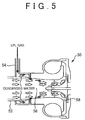
- FIG. 5 is a view for explaining a flow of gas inside a conventional compressor.
- an EGRpassage 54 is connected with an end part of the intake passage 52 on the compressor side. Since a downstream side of the EGR passage 54 is bent into an L shape, it is possible to allow LPL gas to flow along an outer peripheral wall of an inlet 56, and allow intake air to flow on an inner side of the LPL gas. However, since there is a distance from the connection of the EGR passage 54 to an impeller 58, LPL gas and intake air are mixed together on an upstream side of the impeller 58, and temperature of LPL gas can be decreased. Also, it is possible that LPL gas is cooled at the L-shaped bent part in the intake passage 52, thereby generating condensed water.
- the compressor 20 since the end of the gas inlet of the inlet 36 (the end on the intake passage 18 side) is closer to the impeller 30 than an end part of the gas outlet of the intake passage 18, it is possible to introduce LPL gas from a location closer to the impeller 30. Therefore, it is possible to restrain LPL gas and intake air from being mixed together on the upstream side of the impeller 30. In addition, it is possible to allow LPL gas, which overflows from the groove 38, to flow along the outer peripheral wall of the inlet 36 with an improved heat retention property. Hence, it is possible to restrain generation of condensed water derived from LPL gas. Even if condensed water is generated, it is possible to restrain an increase in the size of the condensed water.
- FIG. 6 is a view showing modified examples of the compressor according to the first embodiment.
- a groove diameter of the groove 38 may be machined to become larger towards the impeller 30 from the intake passage 18.
- the groove diameter of the groove 38 may be machined to become smaller towards the impeller 30 from the intake passage 18.
- a groove width of the groove 38 may be machined to become larger towards the impeller 30 from the intake passage 18.
- the shape of the groove 38 may be modified in various ways.
- a blocked end 46 of the groove 38 may be formed on the immediate downstream side of the gas outlet of the EGR passage 24.
- the groove 38 is blocked on the side closer to the impeller 30 than the gas outlet of the EGR passage 24, it is possible to generate a flow of LPL gas explained in FIG. 4 . Therefore, as long as the groove 38 is blocked on the side closer to the impeller 30 than the gas outlet of the EGR passage 24, various modifications may be made in the groove depth of the groove 38 (a distance from the end of gas inlet of the inlet 36 to the blocked end 46).
- FIG. 7 is a view showing a modified example of the intake passage that can be connected with the compressor according to the first embodiment.
- an inner diameter is reduced partially and is increased again on the compressor 20 side.
- intake air which is flown into the inlet 36 from the intake passage 18 side, is sent to the impeller 30 without allowing the intake air to flow into the groove 38.
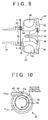
- FIG. 8 is a view showing a modified example of the compressor according to the first embodiment. As shown in FIG. 8 , two gas outlets 44 may be provided.
- the groove 38 communicates with the EGR passage 24 on the side closer to the impeller 30 than a part where the groove 38 communicates with the inlet 36, and the groove 38 is also blocked on the side closer to the impeller 30 than a part where the groove 38 communicates with the EGR passage 24, it is possible to generate the flow of LPL gas explained in FIG. 4 . Therefore, as long as the above-mentioned positional relation is established, various modifications may be made in the number of the gas outlets 44.
- the turbine 16 corresponds to the "exhaust turbine” in the first invention stated above
- the intake passage 18 corresponds to the "intake passage” in the same invention
- the EGR passage 24 corresponds to the "EGR passage” of the same invention
- the impeller 30 corresponds to the "impeller” of the same invention
- the connecting shaft 34 corresponds to the "shaft” of the same invention
- the inlet 36 corresponds to the "inlet” of the same invention
- the groove 38 corresponds to the "circular space” of the same invention.
- a groove 38 and an EGR passage are orthogonal to each other.
- a gas outlet of the EGR passage is arranged in a tangential direction of a sectional circular of the groove 38. This difference is mainly explained below.
- FIG. 9 is an enlarged sectional view of the vicinity of a compressor 60 according to the second embodiment.
- An EGR passage 62 is arranged to be orthogonal to the groove 38.
- a gas outlet 64 of the EGR passage 62 is open in the groove 38.
- FIG. 10 is a sectional view taken along the line A - A' in FIG. 9 .
- the EGR passage 62 is inserted into a housing 32.
- a center axis CA 62 of the EGR passage 62 which passes along the center C 64 of the gas outlet 64, is parallel to the tangent TL 38 of the sectional circle drawn by an inner peripheral wall of the groove 38.
- FIG. 11 is a view for explaining a flow of LPL gas inside the groove 38.
- LPL gas flowing into the groove 38 from the EGR passage 24 collides with the inner peripheral wall of the groove 38, and the flow of LPL gas can thus be disturbed.
- LPL gas, which is flown into the groove 38 from the EGR passage 62 is swirled along an inner peripheral wall of the groove 38 without colliding with the inner peripheral wall. Therefore, a flow rate of LPL gas flowing inside the groove 38 is made uniform, and it is thus possible to equally increase temperature of an outer peripheral wall of an inlet 36.
- a swirling direction of LPL gas is the same as, but may be opposite of, a rotation direction of an impeller.
- the center axis CA 62 is arranged to be parallel to the tangent TL 38 , but the center axis CA 62 may not be parallel to the tangent TL 38 .
- the center axis CA 62 is perpendicular to the tangent TL 38 (in other words, as long as the center axis CA 62 is inclined to the tangent TL 38 side), collision of LPL gas with the inner peripheral wall of the groove 38 is alleviated.
- various modifications may be made in the positional relation between the center axis CA 62 and the tangent TL 38 .
- a gas outlet 44 corresponds to the "gas outlet” in the fifth invention
- the center axis CA 62 corresponds to the "center axis” in the same invention
- the tangent TL 38 corresponds to the "tangent” of the same invention.
- an EGR passage is connected with a groove 38.
- a gas outlet of the EGR passage is arranged so as to face a blocked end of the groove 38 on an impeller 30 side, and also the EGR passage is inclined to a connecting shaft 34 side. This difference is mainly explained below.
- FIG. 12 is an enlarged sectional view of the vicinity of a compressor 70 according to the third embodiment.
- a gas outlet 74 of an EGR passage 72 is arranged so as to face a blocked end 76 of the groove 38.
- a center axis CA 72 of the EGR passage 72, which passes along a center C 74 of the gas outlet 74 is inclined with respect to a rotation center axis CA 34 of a connecting shaft 34.
- FIG. 13 is a view for explaining a flow of LPL gas inside the groove 38.
- FIG. 13(a) corresponds to a flow of LPL gas flown into the groove 38 from the EGR passage 72
- FIG. 13(b) corresponds to a flow of LPL gas flown into the groove 38 from the EGR passage 24 according to the foregoing first embodiment.
- EGR gas overflows from the groove 38, flows along an outer peripheral wall of the inlet 36, and is sent to the impeller 30. This was explained in the foregoing first embodiment.
- LPL gas flown into the groove 38 from the EGR passage 72 collides with and is reflected by the blocked end 76 with a great force, and overflows from the intake passage 18 side ( FIG.
- the compressor 70 of this embodiment it is possible to allow LPL gas, which is flown from the EGR passage 72, to directly collide with and be reflected by the blocked end 76. Therefore, it is possible to generate a strong flow of LPL gas moving inside the groove 38 towards the intake passage 18 side from the blocked end 76. Hence, even if condensed water shown in FIG. 13 is generated inside the groove 38, it is possible to discharge the condensed water outside the groove 38 along the flow.
- the gas outlet 74 corresponds to the "gas outlet” of the foregoing sixth invention
- the blocked end 76 corresponds to the "blocked end” of the same invention
- the center axis CA 72 corresponds to the "center axis” of the same invention
- the rotation center axis CA 34 corresponds to the "rotation center axis” according to the same invention.
- FIG. 14 is an enlarged sectional view of the vicinity of a compressor 80 according to the fourth embodiment.
- a groove depth GD 82 of a groove 82 (a distance from an end of a gas inlet of an inlet 36 to a blocked end 84) is machined to become shallower than a groove depth GD 38 of a groove 38 (a distance from an end of a gas inlet of the inlet 36 to the blocked end 76).
- FIG. 15 is a sectional view taken along the line A- A' in FIG. 14 .
- the groove 82 is formed on an opposite side of a gas outlet 44. Arrows in the drawing show a flow of LPL gas.
- the groove 82 is formed in a downstream area of a swirl flow of LPL gas that is flown in from an EGR passage 24.
- the EGR passage 24 is connected with a housing 32 from above in a gravity direction (a vertical direction). This means that the groove 82 is at a lower position in the gravity direction.
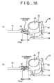
- FIG. 16 is a view for explaining a flow of LPL gas inside the grooves 38, 82.
- FIG. 16(a) corresponds to a flow of LPL gas inside the groove 82
- FIG. 16(b) corresponds to a flow of LPL gas inside the groove 38.
- EGR gas overflows from the grooves 38, 82, flows along an outer peripheral wall of an inlet 36, and is sent to an impeller 30. This was explained in the first embodiment.
- the groove depth CD 82 is machined to be shallower than the groove depth GD 38 , LPL gas inside the groove 82 overflows sooner than LPL gas inside the groove 38.
- the arrows shown in FIG. 16 show moving distances of LPL gas per unit time. This means that EGR gas inside the groove 82 moves to a location closer to the impeller 30 than the EGR gas inside the groove 38.
- the compressor 60 of this embodiment it is possible to send LPL gas inside the groove 82 to the impeller 30 sooner than LPL gas inside the groove 38. Therefore, as shown in FIG. 16 , even if condensed water is generated inside the groove 38, it is possible to send out the condensed water to the impeller 30 side from the groove 82 before the size of the condensed water increases.
- the groove 82 is at a lower position in the gravity direction. Therefore, it is also possible to send out condensed water from the groove 82 more smoothly.
- the groove depth GD 38 is fixed.
- the groove depth GD 38 may be machined to be gradually deeper from the groove 82 towards an upstream area of a swirl flow of EGR gas (towards the gas outlet 44 from the groove 82).
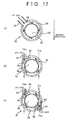
- FIG. 17 is a view showing modified examples of the compressor according to the fourth embodiment. As shown in FIG. 17(a) , the gas outlet 44 may be provided at a lower position in the gravity direction than the position of the gas outlet 44 in FIG. 15 , and the groove 82 may be formed at an upper position in the gravity direction than the position of the groove 82 shown in FIG. 15 .
- FIG. 17(b) is a view showing an example of a location where the groove 82 is formed in the case of FIG. 10 .
- FIG. 17(b) in the case where the center axis CA 62 and TL 38 are parallel to each other, it is possible to form the groove 82 in a downstream area of a swirl flow of EGR gas flown from the gas outlet 64. Further, FIG.
- 17(c) is a view showing an example of locations where the grooves 82 are formed in the case where two gas outlets 64 are arranged. As shown in FIG. 17(c) , in the case where two gas outlets 64 are arranged, it is possible to form the grooves 82 in respective downstream areas of swirl flows of EGR gas flown from the gas outlets 64.
- the blocked end 84 corresponds to "a part of a blocked end" according to the second invention
- the blocked end 76 corresponds to "the other blocked end” of the same invention.
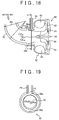
- FIG. 18 is an enlarged sectional view of the vicinity of a compressor 90 according to the fifth embodiment.
- an intake passage 92 is bent to an EGR passage 24 side.
- a rotation center axis CA 34 of a connecting shaft 34 and a center axis CA 38 of a groove 38 do not coincide with each other.
- the center axis CA 38 is offset with respect to the rotation center axis CA 34 to an outer side of bending with a large curvature radius Rb (> Ra).
- FIG. 19 is a sectional view taken along the line A - A' in FIG. 18 .
- the center axis CA 38 is offset to the rotation center axis CA 34 in a direction away from a gas outlet 44.
- the center axis CA 38 corresponds to the "center axis" of the fourth invention stated above, and the rotation center axis CA 34 corresponds to the "rotation center axis” according to the same invention.
Landscapes
- Engineering & Computer Science (AREA)
- Chemical & Material Sciences (AREA)
- Combustion & Propulsion (AREA)
- Mechanical Engineering (AREA)
- General Engineering & Computer Science (AREA)
- Exhaust-Gas Circulating Devices (AREA)
- Supercharger (AREA)
- Structures Of Non-Positive Displacement Pumps (AREA)
Abstract
Description
- The invention relates to a compressor of an exhaust turbocharger, and, more precisely, to a compressor of an exhaust turbocharger that is applied to an exhaust gas recirculation (EGR) system.
- Conventionally, it has been publicly known that EGR gas is introduced to an air intake system of an internal combustion engine. For example, in Patent Document 1, introduction of EGR gas into a compressor of an exhaust turbocharger is disclosed. In this compressor, a circular EGR passage is provided in an outer peripheral area of a housing that houses an impeller. In this circular passage, two recirculation ports are formed for introducing EGR gas into the compressor. The first recirculation port is open in an air passage of an inlet of the impeller. The second recirculation port is open in an air passage on an upstream side of the inlet of the impeller.
- EGR gas, which is flown from an exhaust system of an internal combustion engine into a circular passage, flows along an outer periphery of the circular passage, and is flown into a compressor through the first recirculation port or the second recirculation port depending on an amount of intake air flowing in the intake passage. Specifically, when an amount of intake air is small, EGR gas inside the circular passage is flown into the compressor through the first recirculation port. When the amount of intake air is large, EGR gas inside the circular passage is flown into the compressor through the second recirculation port. This is caused by a difference between pressure inside the circular passage and pressure in the inlet of the impeller. In the compressor having such a structure, it is possible to restrain interference between EGR gas and fresh air when the amount of intake air is small, and, when the amount of intake air is large, it is possible to introduce EGR gas directly into the inlet of the impeller.
-
- Patent Document 1: Japanese Patent Application Publication
2012-140876 A JP 2012-140876 A - Patent Document 2: Japanese Patent Application Publication
2011-032984 A JP 2011-032984 A - Patent Document 3: Japanese Patent Application Publication
2009-108716 A JP 2009-108716 A - Incidentally, EGR gas contains vapor. Therefore, when EGR gas is cooled, there are instances where condensed water is generated. In particular, when outdoor temperature is low, temperature of components of a compressor is also low, and EGR gas is thus cooled by the components, and condensed water could be generated. Condensed water generated is flown into the compressor together with EGR gas and intake air. Here, when a size of condensed water is large, an impeller could be damaged when flown into the compressor. Therefore, it is preferable to restrain generation of condensed water on an upstream side of the impeller as much as possible.
- In this respect, the compressor in the Patent Document 1 has the structure in which intake air is flown into the circular passage from the first recirculation port when the amount of intake air flowing in the intake passage is large. Therefore, in the case where outdoor temperature is low and also the amount of intake air is large, it is possible that an inner wall of the circular passage is cooled by intake air flown into the circular passage from the first recirculation port. Then, because EGR gas is cooled by the inner wall of the circular passage or intake air flown into the circular passage, condensed water can be generated inside the circular passage. In addition, condensed water generated can be combined together inside the circular passage, which can cause an increase in size of condensed water.
- The invention has been accomplished in view of the foregoing problems. In short, an object of the invention is to provide a compressor of an exhaust turbocharger, in which generation of condensed water due to components is restrained.
- In order to achieve the above-mentioned object, the first invention is a compressor of an exhaust turbocharger which includes an impeller coupled with an exhaust turbine shaft, an inlet that communicates with an intake passage of an internal combustion engine on an upstream side of the impeller, and a circular space that is formed so as to surround the inlet and communicates with the inlet and an EGR passage. One end of the circular space on the intake passage side communicates with the inlet, the circular space communicates with the EGR passage at a position closer to the impeller than a position communicated with the inlet, and the circular space is blocked at a position closer to the impeller than a position communicated with the EGR passage. An inner diameter of an end of the inlet on the intake passage side is larger than an inner diameter of an end part of the intake passage on the inlet side.
- Further, the second invention is characterized in that, in the first invention, a position that a part of the circular space is blocked is located closer to the intake passage than a position that the other part of the circular space is blocked.
- Furthermore, the third invention is characterized in that, in the second invention, the part of the circular space blocked is located in a downstream area of a swirl flow of EGR gas that flows in the circular space, in a radial section of the inlet including a gas outlet of the EGR passage, and the other part of the circular space blocked is located so as to be away from the intake passage towards an upstream area of the swirl flow of EGR gas that flows in the circular space.
- Yet further, the fourth invention is characterized in that, in any one of the first to the third inventions, the intake passage is bent on an upstream side of the inlet, and a center axis of the circular space is located closer to an outer side of bending of the intake passage than to a rotation center axis of the shaft.
- Furthermore, the fifth invention is characterized in that, in any one of the first to the fourth inventions, a gas outlet of the EGR passage is inserted into the circular space, and a center axis of the EGR passage, which passes along a center of the gas outlet, is inclined to a side of a tangent of a sectional circle of the circular space, in a radial section of the inlet including the gas outlet.
- Furthermore, the sixth invention is characterized in that, in any one of the first to the fifth inventions, the gas outlet of the EGR passage is arranged so as to face a blocked end of the circular space, and, in an axial section of the inlet including the gas outlet, the center axis of the EGR passage, which passes along the center of the gas outlet, is inclined to a side of the rotation center axis of the shaft.
- According to the first invention, since it is possible to allow EGR gas, which is flown into the circular space from the EGR passage, to overflow from the part communicated with the inlet, and flow along an outer peripheral wall of the inlet, it is possible to restrain intake air from coming into contact with the outer peripheral wall. Therefore, it is possible to restrain a temperature drop of EGR gas due to the outer peripheral wall. Further, it is possible to improve a heat retention property of the outer peripheral wall by flowing the high-temperature EGR gas along the outer peripheral wall. Thus, even if condensed water is generated in the inlet, it is possible to restrain an increase in size of the condensed water as heat is transferred from the outer peripheral wall.
- Further, according to the first invention, since the inner diameter of the end of the inlet on the intake passage side is larger than the inner diameter of the end part of the intake passage on the inlet side, it is possible to restrain intake air from flowing into the circular space. Therefore, it is also possible to restrain a temperature drop of EGR gas due to intake air.
- EGR gas flown into the circular space from the EGR passage is reflected by the blocked end of the circular space, and overflows from the part communicated with the inlet. According to the second invention, since the part of the blocked end is formed on the side closer to the intake passage than the other blocked end, the EGR gas reflected by the part of the blocked end is overflown sooner than EGR gas reflected by the other blocked end. Therefore, even if condensed water is generated in the circular space, it is possible to discharge the condensed water to the inlet before the size of the condensed water is increased.
- According to the third invention, in the radial section of the inlet including the gas outlet of the EGR passage, the part of the blocked end is formed in a downstream area of a swirl flow of EGR gas flowing in the circular space, and the other blocked end is formed so as to be away from the end of the inlet on the intake passage side towards an upstream area of the swirl flow. Therefore, a flow of EGR gas in a radial direction from the other blocked end towards the part of the blocked end is made smooth. Thus, it is possible to improve a discharge property of condensed water that is generated in the circular space.
- According to the fourth invention, since the center axis of the circular space is located on the outer side of bending of the intake passage compared to the rotation center axis of the shaft, it is possible to restrain intake air from flowing into the circular space even when the intake passage is bent on an upstream side of the inlet.
- According to the fifth invention, the gas outlet of the EGR passage is inserted into the circular space, and, in the radial section of the inlet including the gas outlet, the center axis of the EGR passage, which passes along the center of the gas outlet, is inclined to the side of the tangent of the sectional circle of the circular space. Therefore, it is possible to alleviate collision of EGR gas, which is flown into the circular space from the EGR passage, with the inner peripheral wall. Thus, a flow of EGR gas inside the circular space is made smooth.
- According to the sixth invention, the gas outlet of the EGR passage is arranged so as to face the blocked end of the circular space, and, in the axial section of the inlet including the center of the gas outlet, the center axis of the EGR passage, which passes along the center of the gas outlet, is inclined to the side of the rotation center axis of the shaft. Therefore, it is possible to allow EGR gas, which is flown into the circular space from the EGR passage, to collide with and be reflected by the blocked end of the circular space directly. Therefore, EGR gas reflected by the blocked end is overflown in a short period of time. Thus, even if condensed water is generated in the circular space, it is possible to discharge the condensed water to the inlet before the size of the condensed water increases.
-
- [
FIG. 1] FIG. 1 is a view for explaining an entire structure of an EGR system including a compressor according to the first embodiment; - [
FIG. 2] FIG. 2 is an enlarged sectional view of the vicinity of acompressor 20 inFIG. 1 ; - [
FIG. 3] FIG. 3 is a sectional view taken along the line A-A' inFIG. 3 ; - [
FIG. 4] FIG. 4 is a view for explaining a flow of gas inside thecompressor 20 and a heat transfer phenomenon inside ahousing 32; - [
FIG. 5] FIG. 5 is a view for explaining a flow of gas inside a conventional compressor; - [
FIG. 6] FIG. 6 is a view showing modified examples of the compressor of the first embodiment; - [
FIG. 7] FIG. 7 is a view showing a modified example of an intake passage that can be connected with the compressor of the first embodiment; - [
FIG. 8] FIG. 8 is a view showing a modified example of the compressor of the first embodiment; - [
FIG. 9] FIG. 9 is an enlarged sectional view of the vicinity of acompressor 60 of the second embodiment; - [
FIG. 10] FIG. 10 is a sectional view taken along the line A - A' inFIG. 9 ; - [
FIG. 11] FIG. 11 is a view for explaining a flow of LPL gas inside agroove 38; - [
FIG. 12] FIG. 12 is an enlarged sectional view of the vicinity of acompressor 70 of the third embodiment; - [
FIG. 13] FIG. 13 is a view for explaining a flow of LPL gas inside thegroove 38; - [
FIG. 14] FIG. 14 is an enlarged sectional view of the vicinity of acompressor 80 of the fourth embodiment; - [
FIG. 15] FIG. 15 is a sectional view taken along the line A - A' inFIG. 14 ; - [
FIG. 16] FIG. 16 is a view for explaining flows of LPL gas inside thegrooves - [
FIG. 17] FIG. 17 is a view showing modified examples of the compressor of the fourth embodiment; - [
FIG. 18] FIG. 18 is an enlarged sectional view of the vicinity of acompressor 90 of the fifth embodiment; and - [
FIG. 19] FIG. 19 is a sectional view taken along the line A - A' inFIG. 18 . - Herein below, embodiments of the invention are explained in detail with reference to the drawings. Note that the same reference numerals are used for common elements throughout the drawings so as to avoid duplicated explanation.
- First of all, the first embodiment of the invention is explained with reference to
FIG. 1 to FIG. 8 . -
FIG. 1 is a view for explaining an entire structure of an EGR system including a compressor according to the first embodiment. As shown inFIG. 1 , the EGR system is provided with anengine 10 as an internal combustion engine. Each cylinder of theengine 10 is provided with a piston, an intake valve, an exhaust valve, a fuel injector, and so on. The number of cylinders and arrangement of the cylinders of theengine 10 are not particularly limited. - The EGR system includes a
supercharger 12. Thesupercharger 12 includes a turbine 16 provided in theexhaust passage 14, and acompressor 20 provided in anintake passage 18. The turbine 16 and thecompressor 20 are coupled with each other. When thesupercharger 12 is operated, the turbine 16 rotates by receiving exhaust pressure, and, thecompressor 20 is thus driven, and gas flown into thecompressor 20 is compressed. Theintake passage 18 is also provided with anintercooler 22 that cools compressed gas. - The EGR system includes an
EGR passage 24 for introducing low pressure loop (LPL) EGR gas. TheEGR passage 24 connects theexhaust passage 14 on a downstream side of the turbine 16 with thecompressor 20. AnEGR cooler 26 for cooling EGR gas is provided in the middle of theEGR passage 24. AnEGR valve 28, which controls a flow rate of EGR gas, is provided in theEGR passage 24 downstream of theEGR cooler 26. Note that low pressure loop EGR gas is referred to as "LPL gas" in the explanation below. -
FIG. 2 is an enlarged sectional view of the vicinity of thecompressor 20 inFIG. 1 . As shown inFIG. 2 , thecompressor 20 includes animpeller 30, ahousing 32, and a connectingshaft 34. Theimpeller 30 is connected with an impeller (not shown) of the turbine 16 through the connectingshaft 34. Thehousing 32 supports the connectingshaft 34 so that the connectingshaft 34 is able to rotate. In thehousing 32, aninlet 36, which introduces gas to a suction side of theimpeller 30, anannular groove 38 formed in an outer periphery of theinlet 36, aspiral scroll 40 formed in an outer periphery of theimpeller 30, and adiffuser 42 that communicates a discharge side of theimpeller 30 with thescroll 40 are formed. - As shown in
FIG. 2 , an inner diameter ID38 of thegroove 38 is machined so as to be larger than an inner diameter ID18 of an end part of a gas outlet of the intake passage 18 (an end part on the inlet 36side). Further, thegroove 38 is communicated with theinlet 36 on theintake passage 18 side. Thegroove 38 is blocked on theimpeller 30 side. A gas outlet of theEGR passage 24 is connected with the middle of thegroove 38. A downstream end of theEGR passage 24 including the gas outlet is arranged to be orthogonal to thegroove 38.FIG 3 is a sectional view taken along the line A - A' inFIG 2 . As shown inFIG 3 , thegas outlet 44 of theEGR passage 24 is inserted into thehousing 32 and is communicated with thegroove 38. -
FIG. 4 is a view for explaining a flow of gas inside thecompressor 20 and a heat transfer phenomenon inside thehousing 32. As shown inFIG. 4 , LPL gas flown from theEGR passage 24 into thegroove 38 collides with an inner peripheral wall of thegroove 38, and then is dispersed in the entire area inside thegroove 38 while swirling along the inner peripheral wall. Since thegroove 38 is blocked on theimpeller 30 side, LPL gas inside thegroove 38 overflows from theintake passage 18 side. Further, as shown inFIG. 4 , intake air is flown into thecompressor 20 from theintake passage 18 side. Therefore, LPL gas, which overflows from thegroove 38, is sent to theimpeller 30 together with intake air. - As explained in
FIG. 2 , in thecompressor 20, the inner diameter ID38 is machined so as to be larger than the inner diameter ID18. Therefore, as shown inFIG. 4 , intake air flown into theinlet 36 from theintake passage 18 side is sent to theimpeller 30 without flowing into thegroove 38. In addition, LPL gas overflowing from thegroove 38 flows along the outer peripheral wall of theinlet 36. This means that, inside thehousing 32, intake air flows in the center, and LPL gas flows in an outer periphery of the intake air. - According to the
compressor 20 of this embodiment, since it is possible to make the above-mentioned gas flow, mixture of LPL gas and intake air is restrained. Therefore, it is possible to restrain a temperature drop caused by intake air. In particular, since it is possible to allow LPL gas to flow along the outer peripheral wall of theinlet 36, it is possible to restrain intake air from being in contact with the outer peripheral wall. Hence, it is also possible to restrain a temperature drop of LPL gas caused by the outer peripheral wall. Thus, it is possible to prevent generation of condensed water derived from LPL gas. - Because of the series of LPL gas flows, it is also possible to improve a heat retention property of the outer peripheral wall of the
inlet 36. As shown inFIG. 4 , as LPL gas at high temperature (at about 150 °C) flowing in theEGR passage 24 collides with the inner peripheral wall of thegroove 38, temperature of the outer peripheral wall of theinlet 36 increases due to heat transferred from the LPL gas (FIG. 4(i) ). Also, as LPL gas flows along the outer peripheral wall, temperature of the outer peripheral wall also increased near theimpeller 30 due to heat transferred from the LPL gas (FIG. 4(ii) ). Furthermore, temperature of the outer peripheral wall also increases due to heat transferred from LPL gas (at about 100 °C ∼ 150 °C) inside the scroll 40 (FIG. 4(iii) ). Therefore, even when condensed water is generated inside theinlet 36, an increase in size of the condensed water is restrained by heat transfer from the outer peripheral wall. -
FIG. 5 is a view for explaining a flow of gas inside a conventional compressor. As shown inFIG. 5 , in theconventional compressor 50, anEGRpassage 54 is connected with an end part of theintake passage 52 on the compressor side. Since a downstream side of theEGR passage 54 is bent into an L shape, it is possible to allow LPL gas to flow along an outer peripheral wall of aninlet 56, and allow intake air to flow on an inner side of the LPL gas. However, since there is a distance from the connection of theEGR passage 54 to animpeller 58, LPL gas and intake air are mixed together on an upstream side of theimpeller 58, and temperature of LPL gas can be decreased. Also, it is possible that LPL gas is cooled at the L-shaped bent part in theintake passage 52, thereby generating condensed water. - In this respect, in the
compressor 20 according to this embodiment, since the end of the gas inlet of the inlet 36 (the end on theintake passage 18 side) is closer to theimpeller 30 than an end part of the gas outlet of theintake passage 18, it is possible to introduce LPL gas from a location closer to theimpeller 30. Therefore, it is possible to restrain LPL gas and intake air from being mixed together on the upstream side of theimpeller 30. In addition, it is possible to allow LPL gas, which overflows from thegroove 38, to flow along the outer peripheral wall of theinlet 36 with an improved heat retention property. Hence, it is possible to restrain generation of condensed water derived from LPL gas. Even if condensed water is generated, it is possible to restrain an increase in the size of the condensed water. - Incidentally, in the first embodiment, the shape of the
groove 38 is explained usingFIG. 2 as an example. However, the shape of thegroove 38 may be changed in various ways.FIG. 6 is a view showing modified examples of the compressor according to the first embodiment. As shown inFIG. 6(a) , a groove diameter of thegroove 38 may be machined to become larger towards theimpeller 30 from theintake passage 18. Also, as shown inFIG. 6(b) , the groove diameter of thegroove 38 may be machined to become smaller towards theimpeller 30 from theintake passage 18. Further, as shown inFIG. 6(c) , a groove width of thegroove 38 may be machined to become larger towards theimpeller 30 from theintake passage 18. As long as the inner diameter ID36 of the end of the gas inlet of theinlet 36 is machined to become larger than the inner diameter ID18 of the end part of the gas outlet of theintake passage 18, it is possible to restrain intake air from flowing into thegroove 38. Thus, as long as the inner diameter ID36 is machined to be larger than the inner diameter ID18, the shape of thegroove 38 may be modified in various ways. - Furthermore, as shown in
FIG. 6(d) , a blockedend 46 of thegroove 38 may be formed on the immediate downstream side of the gas outlet of theEGR passage 24. As long as thegroove 38 is blocked on the side closer to theimpeller 30 than the gas outlet of theEGR passage 24, it is possible to generate a flow of LPL gas explained inFIG. 4 . Therefore, as long as thegroove 38 is blocked on the side closer to theimpeller 30 than the gas outlet of theEGR passage 24, various modifications may be made in the groove depth of the groove 38 (a distance from the end of gas inlet of theinlet 36 to the blocked end 46). - In the foregoing first embodiment, the inner diameter of the end part of the gas outlet of the
intake passage 18 is fixed, but may not necessarily be fixed.FIG. 7 is a view showing a modified example of the intake passage that can be connected with the compressor according to the first embodiment. As shown inFIG. 7 , in an end part of a gas outlet of anintake passage 48, an inner diameter is reduced partially and is increased again on thecompressor 20 side. With such anintake passage 48, intake air, which is flown into theinlet 36 from theintake passage 18 side, is sent to theimpeller 30 without allowing the intake air to flow into thegroove 38. As long as the inner diameter ID36 of the end of the gas inlet of theinlet 36 is machined to become larger than the minimum inner diameter ID48 in the end part of the gas outlet of theintake passage 48, various modifications may be made in the shape of the end part of the gas outlet of theintake passage 18. - Further, in the first embodiment, there is one gas outlet in the
EGR passage 24, but there may be a plurality of gas outlets.FIG. 8 is a view showing a modified example of the compressor according to the first embodiment. As shown inFIG. 8 , twogas outlets 44 may be provided. When thegroove 38 communicates with theEGR passage 24 on the side closer to theimpeller 30 than a part where thegroove 38 communicates with theinlet 36, and thegroove 38 is also blocked on the side closer to theimpeller 30 than a part where thegroove 38 communicates with theEGR passage 24, it is possible to generate the flow of LPL gas explained inFIG. 4 . Therefore, as long as the above-mentioned positional relation is established, various modifications may be made in the number of thegas outlets 44. - In the foregoing first embodiment, the turbine 16 corresponds to the "exhaust turbine" in the first invention stated above, the
intake passage 18 corresponds to the "intake passage" in the same invention, theEGR passage 24 corresponds to the "EGR passage" of the same invention, theimpeller 30 corresponds to the "impeller" of the same invention, the connectingshaft 34 corresponds to the "shaft" of the same invention, and theinlet 36 corresponds to the "inlet" of the same invention, and thegroove 38 corresponds to the "circular space" of the same invention. - Next, the second embodiment of the invention is explained with reference to
FIG. 9 to FIG. 11 . - In a compressor according to this embodiment, similarly to the foregoing first embodiment, a
groove 38 and an EGR passage are orthogonal to each other. However, in this embodiment, there is a difference from theEGR passage 24 of the first embodiment in that a gas outlet of the EGR passage is arranged in a tangential direction of a sectional circular of thegroove 38. This difference is mainly explained below. -
FIG. 9 is an enlarged sectional view of the vicinity of acompressor 60 according to the second embodiment. AnEGR passage 62 is arranged to be orthogonal to thegroove 38. As shown inFIG. 9 , agas outlet 64 of theEGR passage 62 is open in thegroove 38.FIG. 10 is a sectional view taken along the line A - A' inFIG. 9 . As shown inFIG. 10 , theEGR passage 62 is inserted into ahousing 32. Further, a center axis CA62 of theEGR passage 62, which passes along the center C64 of thegas outlet 64, is parallel to the tangent TL38 of the sectional circle drawn by an inner peripheral wall of thegroove 38. -
FIG. 11 is a view for explaining a flow of LPL gas inside thegroove 38. In the foregoing first embodiment, LPL gas flowing into thegroove 38 from theEGR passage 24 collides with the inner peripheral wall of thegroove 38, and the flow of LPL gas can thus be disturbed. In this respect, as shown inFIG. 11 , with thecompressor 60, LPL gas, which is flown into thegroove 38 from theEGR passage 62, is swirled along an inner peripheral wall of thegroove 38 without colliding with the inner peripheral wall. Therefore, a flow rate of LPL gas flowing inside thegroove 38 is made uniform, and it is thus possible to equally increase temperature of an outer peripheral wall of aninlet 36. Note that, inFIG. 10 andFIG. 11 , a swirling direction of LPL gas is the same as, but may be opposite of, a rotation direction of an impeller. - Incidentally, in the foregoing second embodiment, the center axis CA62 is arranged to be parallel to the tangent TL38, but the center axis CA62 may not be parallel to the tangent TL38. Unless the center axis CA62 is perpendicular to the tangent TL38 (in other words, as long as the center axis CA62 is inclined to the tangent TL38 side), collision of LPL gas with the inner peripheral wall of the
groove 38 is alleviated. Thus, as long as the center axis CA62 is inclined to the tangent TL38 side, various modifications may be made in the positional relation between the center axis CA62 and the tangent TL38. - In the foregoing second embodiment, a
gas outlet 44 corresponds to the "gas outlet" in the fifth invention, the center axis CA62 corresponds to the "center axis" in the same invention, and the tangent TL38 corresponds to the "tangent" of the same invention. - Next, the third embodiment of the invention is explained with reference to
FIG. 12 to FIG. 13 . - In a compressor according to this embodiment, similarly to the first embodiment, an EGR passage is connected with a
groove 38. However, in this embodiment, there is a difference from theEGR passage 24 of the foregoing first embodiment in that a gas outlet of the EGR passage is arranged so as to face a blocked end of thegroove 38 on animpeller 30 side, and also the EGR passage is inclined to a connectingshaft 34 side. This difference is mainly explained below. -
FIG. 12 is an enlarged sectional view of the vicinity of acompressor 70 according to the third embodiment. As shown inFIG. 12 , agas outlet 74 of anEGR passage 72 is arranged so as to face a blockedend 76 of thegroove 38. Also, a center axis CA72 of theEGR passage 72, which passes along a center C74 of thegas outlet 74 is inclined with respect to a rotation center axis CA34 of a connectingshaft 34. -
FIG. 13 is a view for explaining a flow of LPL gas inside thegroove 38.FIG. 13(a) corresponds to a flow of LPL gas flown into thegroove 38 from theEGR passage 72, andFIG. 13(b) corresponds to a flow of LPL gas flown into thegroove 38 from theEGR passage 24 according to the foregoing first embodiment. As shown inFIG. 13 , EGR gas overflows from thegroove 38, flows along an outer peripheral wall of theinlet 36, and is sent to theimpeller 30. This was explained in the foregoing first embodiment. However, LPL gas flown into thegroove 38 from theEGR passage 72 collides with and is reflected by the blockedend 76 with a great force, and overflows from theintake passage 18 side (FIG. 13(a) ). On the other hand, LPL gas flown from theEGR passage 24 into thegroove 38 collides with an inner peripheral wall of thegroove 38 before colliding with and being reflected by the blockedend 46, and then overflows from theintake passage 18 side (FIG. 13(b) ). This is because the center axis CA24 of theEGR passage 24, which passes along the center C44 of thegas outlet 44, makes a right angle with the rotation center axis CA34. - According to the
compressor 70 of this embodiment, it is possible to allow LPL gas, which is flown from theEGR passage 72, to directly collide with and be reflected by the blockedend 76. Therefore, it is possible to generate a strong flow of LPL gas moving inside thegroove 38 towards theintake passage 18 side from the blockedend 76. Hence, even if condensed water shown inFIG. 13 is generated inside thegroove 38, it is possible to discharge the condensed water outside thegroove 38 along the flow. - In the foregoing third embodiment, the
gas outlet 74 corresponds to the "gas outlet" of the foregoing sixth invention, the blockedend 76 corresponds to the "blocked end" of the same invention, the center axis CA72 corresponds to the "center axis" of the same invention, and the rotation center axis CA34 corresponds to the "rotation center axis" according to the same invention. - Next, the fourth embodiment of the invention is explained with reference to
FIG. 14 to FIG. 17 . -
FIG. 14 is an enlarged sectional view of the vicinity of acompressor 80 according to the fourth embodiment. As shown inFIG. 14 , a groove depth GD82 of a groove 82 (a distance from an end of a gas inlet of aninlet 36 to a blocked end 84) is machined to become shallower than a groove depth GD38 of a groove 38 (a distance from an end of a gas inlet of theinlet 36 to the blocked end 76).FIG. 15 is a sectional view taken along the line A- A' inFIG. 14 . As shown inFIG. 15 , thegroove 82 is formed on an opposite side of agas outlet 44. Arrows in the drawing show a flow of LPL gas. In short, thegroove 82 is formed in a downstream area of a swirl flow of LPL gas that is flown in from anEGR passage 24. Note that, in this embodiment, theEGR passage 24 is connected with ahousing 32 from above in a gravity direction (a vertical direction). This means that thegroove 82 is at a lower position in the gravity direction. -
FIG. 16 is a view for explaining a flow of LPL gas inside thegrooves FIG. 16(a) corresponds to a flow of LPL gas inside thegroove 82, andFIG. 16(b) corresponds to a flow of LPL gas inside thegroove 38. As shown inFIG. 16 , EGR gas overflows from thegrooves inlet 36, and is sent to animpeller 30. This was explained in the first embodiment. However, in thecompressor 80, since the groove depth CD82 is machined to be shallower than the groove depth GD38, LPL gas inside thegroove 82 overflows sooner than LPL gas inside thegroove 38. The arrows shown inFIG. 16 show moving distances of LPL gas per unit time. This means that EGR gas inside thegroove 82 moves to a location closer to theimpeller 30 than the EGR gas inside thegroove 38. - According to the
compressor 60 of this embodiment, it is possible to send LPL gas inside thegroove 82 to theimpeller 30 sooner than LPL gas inside thegroove 38. Therefore, as shown inFIG. 16 , even if condensed water is generated inside thegroove 38, it is possible to send out the condensed water to theimpeller 30 side from thegroove 82 before the size of the condensed water increases. In this embodiment, thegroove 82 is at a lower position in the gravity direction. Therefore, it is also possible to send out condensed water from thegroove 82 more smoothly. - Incidentally, in the foregoing fourth embodiment, the groove depth GD38 is fixed. However, the groove depth GD38 may be machined to be gradually deeper from the
groove 82 towards an upstream area of a swirl flow of EGR gas (towards thegas outlet 44 from the groove 82). By machining the groove depth GD38 like this, it is possible to send out condensed water from thegroove 82 more smoothly. - Also, in the foregoing fourth embodiment, the
gas outlet 44 is provided in an upper position in the gravity direction, and thegroove 82 is formed at a lower position in the gravity direction. However, locations where thegas outlet 44 is provided and thegroove 82 are formed are not limited to the examples in the foregoing fourth embodiment.FIG. 17 is a view showing modified examples of the compressor according to the fourth embodiment. As shown inFIG. 17(a) , thegas outlet 44 may be provided at a lower position in the gravity direction than the position of thegas outlet 44 inFIG. 15 , and thegroove 82 may be formed at an upper position in the gravity direction than the position of thegroove 82 shown inFIG. 15 . - The locations where the
gas outlet 44 is arranged and thegroove 82 is formed may be similarly modified in a case where thegas outlet 64 is arranged in the tangential direction of the sectional circle of thegroove 38 like the foregoing second embodiment, and in a case where the number ofgas outlets 64 is increased.FIG. 17(b) is a view showing an example of a location where thegroove 82 is formed in the case ofFIG. 10 . As shown inFIG. 17(b) , in the case where the center axis CA62 and TL38 are parallel to each other, it is possible to form thegroove 82 in a downstream area of a swirl flow of EGR gas flown from thegas outlet 64. Further,FIG. 17(c) is a view showing an example of locations where thegrooves 82 are formed in the case where twogas outlets 64 are arranged. As shown inFIG. 17(c) , in the case where twogas outlets 64 are arranged, it is possible to form thegrooves 82 in respective downstream areas of swirl flows of EGR gas flown from thegas outlets 64. - In other words, by forming the
grooves 82 in downstream areas of swirl flows of EGR gas flown from thegas outlets grooves 82. In addition, as long as thegroove 82 is formed, it is possible to send out condensed water from thegroove 82. Therefore, as long as thegrove 82 is formed, various modifications may be made in this embodiment. - Note that, in the foregoing fourth embodiment, the blocked
end 84 corresponds to "a part of a blocked end" according to the second invention, and the blockedend 76 corresponds to "the other blocked end" of the same invention. - Next, the fifth embodiment of the invention is explained with reference to
FIG. 18 to FIG. 19 . -
FIG. 18 is an enlarged sectional view of the vicinity of acompressor 90 according to the fifth embodiment. As shown inFIG. 18 , anintake passage 92 is bent to anEGR passage 24 side. Also, a rotation center axis CA34 of a connectingshaft 34 and a center axis CA38 of agroove 38 do not coincide with each other. To be specific, the center axis CA38 is offset with respect to the rotation center axis CA34 to an outer side of bending with a large curvature radius Rb (> Ra).FIG. 19 is a sectional view taken along the line A - A' inFIG. 18 . As shown inFIG. 19 , the center axis CA38 is offset to the rotation center axis CA34 in a direction away from agas outlet 44. - When the
intake passage 92 is bent, centrifugal force acts on intake air. Therefore, intake air is easily flown into agroove 38b located on the outer side of the bending, compared to agroove 38a located on an inner side of the bending. In this respect, in thecompressor 90, since the center axis CA38 is offset to the outer side of the bending, it is possible to restrain an inflow of intake air into thegroove 38b located on the outer side of the bending. - In the foregoing fifth embodiment, the center axis CA38 corresponds to the "center axis" of the fourth invention stated above, and the rotation center axis CA34 corresponds to the "rotation center axis" according to the same invention.
-
- 10: ENGINE
- 16: TURBINE
- 18, 52, 92: INTAKE PASSAGE
- 20, 50, 60, 70, 80, 90: COMPRESSOR
- 24, 54, 62, 72: EGR PASSAGE
- 30, 58: IMPELLER
- 32: HOUSING
- 34: CONNECTING SHAFT
- 36, 56: INLET
- 38, 82: GROOVE
- 44, 64, 74: GAS OUTLET
- 46, 76, 84: BLOCKED END
Claims (6)
- A compressor of an exhaust turbocharger characterized by comprising:an impeller coupled with an exhaust turbine shaft;an inlet that communicates with an intake passage of an internal combustion engine on an upstream side of the impeller; andan circular space that is formed so as to surround the inlet and communicates with the inlet and an EGR passage, whereinone end of the circular space on the intake passage side communicates with the inlet, the circular space is communicated with the EGR passage at a position closer to the impeller than a position communicated with the inlet, and the circular space is blocked at a position closer to the impeller than a position communicated with the EGR passage, andan inner diameter of an end of the inlet on the intake passage side is larger than an inner diameter of an end part of the intake passage on the inlet side.
- The compressor of the exhaust turbocharger according to claim 1, characterized in that a position in that a part of the circular space is blocked is located closer to the intake passage than a position in that another part of the circular space is blocked.
- The compressor of the exhaust turbocharger according to claim 2, characterized in that the part of the circular space being blocked is located in a downstream area of a swirl flow of EGR gas that flows in the circular space, in a radial section of the inlet including a gas outlet of the EGR passage, and
the other part of the circular space being blocked is located so as to be away from the intake passage towards an upstream area of the swirl flow of EGR gas that flows in the circular space. - The compressor of the exhaust turbocharger according to any one of claims 1 to 3, characterized in that the intake passage is bent on an upstream side of the inlet, and
a center axis of the circular space is located on an outer side of bending of the intake passage compared to a rotation center axis of the shaft. - The compressor of the exhaust turbocharger according to any one of claims 1 to 4, characterized in that a gas outlet of the EGR passage is inserted into the circular space, and
a center axis of the EGR passage, which passes along a center of the gas outlet, is inclined to a side of a tangent of a sectional circle of the circular space, in a radial section of the inlet including the gas outlet. - The compressor of the exhaust turbocharger according to any one of claims 1 to 5, characterized in that a gas outlet of the EGR passage is arranged so as to face a blocked end of the circular space, and
the center axis of the EGR passage, which passes along the center of the gas outlet, is inclined to a side of the rotation center axis of the shaft, in an axial section of the inlet including the gas outlet.
Applications Claiming Priority (1)
| Application Number | Priority Date | Filing Date | Title |
|---|---|---|---|
| PCT/JP2013/061284 WO2014170954A1 (en) | 2013-04-16 | 2013-04-16 | Compressor for exhaust-gas turbo-supercharger |
Publications (3)
| Publication Number | Publication Date |
|---|---|
| EP2987983A1 true EP2987983A1 (en) | 2016-02-24 |
| EP2987983A4 EP2987983A4 (en) | 2016-04-27 |
| EP2987983B1 EP2987983B1 (en) | 2018-08-01 |
Family
ID=51730927
Family Applications (1)
| Application Number | Title | Priority Date | Filing Date |
|---|---|---|---|
| EP13882463.6A Not-in-force EP2987983B1 (en) | 2013-04-16 | 2013-04-16 | Compressor for exhaust-gas turbo-supercharger |
Country Status (5)
| Country | Link |
|---|---|
| US (1) | US10329999B2 (en) |
| EP (1) | EP2987983B1 (en) |
| JP (1) | JP6004091B2 (en) |
| CN (1) | CN105102787B (en) |
| WO (1) | WO2014170954A1 (en) |
Cited By (3)
| Publication number | Priority date | Publication date | Assignee | Title |
|---|---|---|---|---|
| GB2546538A (en) * | 2016-01-21 | 2017-07-26 | Gm Global Tech Operations Llc | A compressor housing |
| EP3244035B1 (en) * | 2016-05-09 | 2019-05-08 | Volkswagen Aktiengesellschaft | Compressor, exhaust gas turbocharger and combustion engine |
| FR3095478A1 (en) * | 2019-04-25 | 2020-10-30 | Renault S.A.S | Device for mixing fresh air and recycled exhaust gases for an internal combustion engine |
Families Citing this family (13)
| Publication number | Priority date | Publication date | Assignee | Title |
|---|---|---|---|---|
| CN105339624B (en) * | 2013-06-26 | 2018-06-05 | 丰田自动车株式会社 | Exhaust gas recirculation for internal combustion engines |
| GB2535996B (en) * | 2015-02-27 | 2019-12-11 | Ford Global Tech Llc | A low condensation LP EGR System |
| DE102015209666A1 (en) | 2015-05-27 | 2016-12-01 | Volkswagen Aktiengesellschaft | compressor |
| JP2017015025A (en) * | 2015-07-02 | 2017-01-19 | 本田技研工業株式会社 | Compressor structure |
| JP6371259B2 (en) * | 2015-07-02 | 2018-08-08 | 本田技研工業株式会社 | Compressor structure |
| US10697358B2 (en) * | 2016-10-11 | 2020-06-30 | Mazda Motor Corporation | Intake passage structure for turbocharger-equipped engine |
| DE102017210648A1 (en) * | 2017-06-23 | 2018-12-27 | Ford Global Technologies, Llc | Condensate trap in a compressor inlet |
| US10590835B2 (en) | 2017-07-31 | 2020-03-17 | ESS Engineering A/S | Supercharger |
| US20190040824A1 (en) * | 2017-08-03 | 2019-02-07 | GM Global Technology Operations LLC | Long route-egr connection for compressor inlet swirl control |
| JP6455581B1 (en) * | 2017-11-17 | 2019-01-23 | マツダ株式会社 | ENGINE CONTROL DEVICE AND ENGINE CONTROL METHOD |
| DE102020112870B4 (en) * | 2020-05-12 | 2022-03-24 | Borgwarner Inc. | Compressor device of a charging device for an internal combustion engine |
| JP7521367B2 (en) * | 2020-10-05 | 2024-07-24 | 三菱自動車工業株式会社 | Internal combustion engine |
| JP7529620B2 (en) | 2021-06-16 | 2024-08-06 | 三菱重工エンジン&ターボチャージャ株式会社 | Pipe branching device and compressor |
Family Cites Families (15)
| Publication number | Priority date | Publication date | Assignee | Title |
|---|---|---|---|---|
| US6138651A (en) | 1997-05-30 | 2000-10-31 | Nissan Motor Co., Ltd. | Exhaust gas recirculation system for engine |
| JP3675150B2 (en) | 1998-01-26 | 2005-07-27 | 日産自動車株式会社 | Engine exhaust gas recirculation system |
| JP2007154675A (en) * | 2005-11-30 | 2007-06-21 | Toyota Motor Corp | Internal combustion engine |
| KR20080095844A (en) * | 2006-01-27 | 2008-10-29 | 보그워너 인코포레이티드 | Reintroduction unit of low pressure EBR condensate in front of / with compressor |
| JP5018400B2 (en) | 2007-06-21 | 2012-09-05 | トヨタ自動車株式会社 | Exhaust gas recirculation device for internal combustion engine |
| JP5076809B2 (en) | 2007-10-29 | 2012-11-21 | トヨタ自動車株式会社 | Foreign matter removing device for internal combustion engine |
| JP2010090806A (en) * | 2008-10-08 | 2010-04-22 | Toyota Industries Corp | Exhaust gas recirculation system |
| US9518591B2 (en) * | 2008-11-18 | 2016-12-13 | Borgwarner Inc. | Compressor of an exhaust-gas turbocharger |
| JP5310367B2 (en) | 2009-08-05 | 2013-10-09 | 株式会社デンソー | Exhaust gas recirculation device |
| US9091275B2 (en) * | 2009-09-03 | 2015-07-28 | Honeywell International Inc. | Integrated EGR mixer and ported shroud housing compressor |
| DE102010021929A1 (en) * | 2010-05-28 | 2011-12-01 | Daimler Ag | Intake tract for an internal combustion engine |
| JP5747483B2 (en) * | 2010-11-16 | 2015-07-15 | 株式会社Ihi | Low pressure loop EGR device |
| JP5047352B2 (en) | 2010-12-28 | 2012-10-10 | 三菱重工業株式会社 | Exhaust turbocharger housing structure |
| JP5729112B2 (en) * | 2011-04-27 | 2015-06-03 | トヨタ自動車株式会社 | Supercharger for internal combustion engine |
| DE112013005165T5 (en) * | 2012-11-28 | 2015-08-13 | Borgwarner Inc. | Compressor stage of a turbocharger with flow amplifier |
-
2013
- 2013-04-16 CN CN201380075505.8A patent/CN105102787B/en not_active Expired - Fee Related
- 2013-04-16 US US14/784,327 patent/US10329999B2/en active Active
- 2013-04-16 WO PCT/JP2013/061284 patent/WO2014170954A1/en not_active Ceased
- 2013-04-16 JP JP2015512220A patent/JP6004091B2/en not_active Expired - Fee Related
- 2013-04-16 EP EP13882463.6A patent/EP2987983B1/en not_active Not-in-force
Cited By (3)
| Publication number | Priority date | Publication date | Assignee | Title |
|---|---|---|---|---|
| GB2546538A (en) * | 2016-01-21 | 2017-07-26 | Gm Global Tech Operations Llc | A compressor housing |
| EP3244035B1 (en) * | 2016-05-09 | 2019-05-08 | Volkswagen Aktiengesellschaft | Compressor, exhaust gas turbocharger and combustion engine |
| FR3095478A1 (en) * | 2019-04-25 | 2020-10-30 | Renault S.A.S | Device for mixing fresh air and recycled exhaust gases for an internal combustion engine |
Also Published As
| Publication number | Publication date |
|---|---|
| EP2987983A4 (en) | 2016-04-27 |
| US20160069302A1 (en) | 2016-03-10 |
| CN105102787A (en) | 2015-11-25 |
| US10329999B2 (en) | 2019-06-25 |
| JP6004091B2 (en) | 2016-10-05 |
| WO2014170954A1 (en) | 2014-10-23 |
| JPWO2014170954A1 (en) | 2017-02-16 |
| CN105102787B (en) | 2017-07-11 |
| EP2987983B1 (en) | 2018-08-01 |
Similar Documents
| Publication | Publication Date | Title |
|---|---|---|
| EP2987983B1 (en) | Compressor for exhaust-gas turbo-supercharger | |
| US9091275B2 (en) | Integrated EGR mixer and ported shroud housing compressor | |
| CN103097692B (en) | Nozzled turbocharger turbine | |
| US9518591B2 (en) | Compressor of an exhaust-gas turbocharger | |
| US10301952B2 (en) | Dual volute turbocharger to optimize pulse energy separation for fuel economy and EGR utilization via asymmetric dual volutes | |
| CN106030042B (en) | Turbine shroud | |
| CN105229264B (en) | Turbine and the internal combustion engine with the turbine | |
| US8820071B2 (en) | Integrated compressor housing and inlet | |
| US10036353B2 (en) | Exhaust gas recirculation apparatus and engine system including such exhaust gas recirculation apparatus | |
| EP2700823B1 (en) | Compressor housing assembly | |
| JP5966589B2 (en) | Low pressure loop EGR device | |
| CN104350286A (en) | Compressor diffuser with vanes comprising variable cross-section | |
| CN103732881A (en) | Nozzled turbocharger turbine and associated engine and method | |
| JP2012107551A (en) | Low-pressure-loop egr device | |
| CN102877898A (en) | Housing assembly for forced air induction system | |
| KR20120036932A (en) | Compressor impeller | |
| US9541095B2 (en) | Housing of a radial compressor | |
| CN105298921B (en) | U-shaped mixing diffuser between two-stage centrifugal compressor stage | |
| CN119244566B (en) | Housing for compressor, compressor and exhaust gas recirculation system | |
| CN223594526U (en) | Air entrainment baffle subassembly and compressor | |
| EP3730758A1 (en) | Internal combustion engine with supercharger |
Legal Events
| Date | Code | Title | Description |
|---|---|---|---|
| PUAI | Public reference made under article 153(3) epc to a published international application that has entered the european phase |
Free format text: ORIGINAL CODE: 0009012 |
|
| 17P | Request for examination filed |
Effective date: 20151012 |
|
| AK | Designated contracting states |
Kind code of ref document: A1 Designated state(s): AL AT BE BG CH CY CZ DE DK EE ES FI FR GB GR HR HU IE IS IT LI LT LU LV MC MK MT NL NO PL PT RO RS SE SI SK SM TR |
|
| AX | Request for extension of the european patent |
Extension state: BA ME |
|
| A4 | Supplementary search report drawn up and despatched |
Effective date: 20160331 |
|
| RIC1 | Information provided on ipc code assigned before grant |
Ipc: F02M 26/34 20160101ALI20160323BHEP Ipc: F02M 26/19 20160101ALI20160323BHEP Ipc: F02B 39/00 20060101ALI20160323BHEP Ipc: F02B 37/12 20060101ALI20160323BHEP Ipc: F02B 37/00 20060101ALI20160323BHEP Ipc: F02B 39/16 20060101AFI20160323BHEP Ipc: F02M 26/06 20160101ALI20160323BHEP |
|
| DAX | Request for extension of the european patent (deleted) | ||
| STAA | Information on the status of an ep patent application or granted ep patent |
Free format text: STATUS: EXAMINATION IS IN PROGRESS |
|
| 17Q | First examination report despatched |
Effective date: 20170707 |
|
| GRAP | Despatch of communication of intention to grant a patent |
Free format text: ORIGINAL CODE: EPIDOSNIGR1 |
|
| STAA | Information on the status of an ep patent application or granted ep patent |
Free format text: STATUS: GRANT OF PATENT IS INTENDED |
|
| INTG | Intention to grant announced |
Effective date: 20180223 |
|
| GRAS | Grant fee paid |
Free format text: ORIGINAL CODE: EPIDOSNIGR3 |
|
| GRAA | (expected) grant |
Free format text: ORIGINAL CODE: 0009210 |
|
| STAA | Information on the status of an ep patent application or granted ep patent |
Free format text: STATUS: THE PATENT HAS BEEN GRANTED |
|
| AK | Designated contracting states |
Kind code of ref document: B1 Designated state(s): AL AT BE BG CH CY CZ DE DK EE ES FI FR GB GR HR HU IE IS IT LI LT LU LV MC MK MT NL NO PL PT RO RS SE SI SK SM TR |
|
| REG | Reference to a national code |
Ref country code: GB Ref legal event code: FG4D |
|
| REG | Reference to a national code |
Ref country code: CH Ref legal event code: EP Ref country code: AT Ref legal event code: REF Ref document number: 1024568 Country of ref document: AT Kind code of ref document: T Effective date: 20180815 |
|
| REG | Reference to a national code |
Ref country code: IE Ref legal event code: FG4D |
|
| REG | Reference to a national code |
Ref country code: DE Ref legal event code: R096 Ref document number: 602013041406 Country of ref document: DE |
|
| REG | Reference to a national code |
Ref country code: DE Ref legal event code: R084 Ref document number: 602013041406 Country of ref document: DE |
|
| REG | Reference to a national code |
Ref country code: GB Ref legal event code: 746 Effective date: 20180927 |
|
| REG | Reference to a national code |
Ref country code: NL Ref legal event code: MP Effective date: 20180801 |
|
| REG | Reference to a national code |
Ref country code: LT Ref legal event code: MG4D |
|
| REG | Reference to a national code |
Ref country code: AT Ref legal event code: MK05 Ref document number: 1024568 Country of ref document: AT Kind code of ref document: T Effective date: 20180801 |
|
| PG25 | Lapsed in a contracting state [announced via postgrant information from national office to epo] |
Ref country code: PL Free format text: LAPSE BECAUSE OF FAILURE TO SUBMIT A TRANSLATION OF THE DESCRIPTION OR TO PAY THE FEE WITHIN THE PRESCRIBED TIME-LIMIT Effective date: 20180801 Ref country code: RS Free format text: LAPSE BECAUSE OF FAILURE TO SUBMIT A TRANSLATION OF THE DESCRIPTION OR TO PAY THE FEE WITHIN THE PRESCRIBED TIME-LIMIT Effective date: 20180801 Ref country code: IS Free format text: LAPSE BECAUSE OF FAILURE TO SUBMIT A TRANSLATION OF THE DESCRIPTION OR TO PAY THE FEE WITHIN THE PRESCRIBED TIME-LIMIT Effective date: 20181201 Ref country code: LT Free format text: LAPSE BECAUSE OF FAILURE TO SUBMIT A TRANSLATION OF THE DESCRIPTION OR TO PAY THE FEE WITHIN THE PRESCRIBED TIME-LIMIT Effective date: 20180801 Ref country code: NL Free format text: LAPSE BECAUSE OF FAILURE TO SUBMIT A TRANSLATION OF THE DESCRIPTION OR TO PAY THE FEE WITHIN THE PRESCRIBED TIME-LIMIT Effective date: 20180801 Ref country code: BG Free format text: LAPSE BECAUSE OF FAILURE TO SUBMIT A TRANSLATION OF THE DESCRIPTION OR TO PAY THE FEE WITHIN THE PRESCRIBED TIME-LIMIT Effective date: 20181101 Ref country code: SE Free format text: LAPSE BECAUSE OF FAILURE TO SUBMIT A TRANSLATION OF THE DESCRIPTION OR TO PAY THE FEE WITHIN THE PRESCRIBED TIME-LIMIT Effective date: 20180801 Ref country code: GR Free format text: LAPSE BECAUSE OF FAILURE TO SUBMIT A TRANSLATION OF THE DESCRIPTION OR TO PAY THE FEE WITHIN THE PRESCRIBED TIME-LIMIT Effective date: 20181102 Ref country code: FI Free format text: LAPSE BECAUSE OF FAILURE TO SUBMIT A TRANSLATION OF THE DESCRIPTION OR TO PAY THE FEE WITHIN THE PRESCRIBED TIME-LIMIT Effective date: 20180801 Ref country code: AT Free format text: LAPSE BECAUSE OF FAILURE TO SUBMIT A TRANSLATION OF THE DESCRIPTION OR TO PAY THE FEE WITHIN THE PRESCRIBED TIME-LIMIT Effective date: 20180801 Ref country code: NO Free format text: LAPSE BECAUSE OF FAILURE TO SUBMIT A TRANSLATION OF THE DESCRIPTION OR TO PAY THE FEE WITHIN THE PRESCRIBED TIME-LIMIT Effective date: 20181101 |
|
| PG25 | Lapsed in a contracting state [announced via postgrant information from national office to epo] |
Ref country code: HR Free format text: LAPSE BECAUSE OF FAILURE TO SUBMIT A TRANSLATION OF THE DESCRIPTION OR TO PAY THE FEE WITHIN THE PRESCRIBED TIME-LIMIT Effective date: 20180801 Ref country code: LV Free format text: LAPSE BECAUSE OF FAILURE TO SUBMIT A TRANSLATION OF THE DESCRIPTION OR TO PAY THE FEE WITHIN THE PRESCRIBED TIME-LIMIT Effective date: 20180801 Ref country code: AL Free format text: LAPSE BECAUSE OF FAILURE TO SUBMIT A TRANSLATION OF THE DESCRIPTION OR TO PAY THE FEE WITHIN THE PRESCRIBED TIME-LIMIT Effective date: 20180801 |
|
| PG25 | Lapsed in a contracting state [announced via postgrant information from national office to epo] |
Ref country code: RO Free format text: LAPSE BECAUSE OF FAILURE TO SUBMIT A TRANSLATION OF THE DESCRIPTION OR TO PAY THE FEE WITHIN THE PRESCRIBED TIME-LIMIT Effective date: 20180801 Ref country code: CZ Free format text: LAPSE BECAUSE OF FAILURE TO SUBMIT A TRANSLATION OF THE DESCRIPTION OR TO PAY THE FEE WITHIN THE PRESCRIBED TIME-LIMIT Effective date: 20180801 Ref country code: ES Free format text: LAPSE BECAUSE OF FAILURE TO SUBMIT A TRANSLATION OF THE DESCRIPTION OR TO PAY THE FEE WITHIN THE PRESCRIBED TIME-LIMIT Effective date: 20180801 Ref country code: EE Free format text: LAPSE BECAUSE OF FAILURE TO SUBMIT A TRANSLATION OF THE DESCRIPTION OR TO PAY THE FEE WITHIN THE PRESCRIBED TIME-LIMIT Effective date: 20180801 |
|
| REG | Reference to a national code |
Ref country code: DE Ref legal event code: R097 Ref document number: 602013041406 Country of ref document: DE |
|
| PG25 | Lapsed in a contracting state [announced via postgrant information from national office to epo] |
Ref country code: DK Free format text: LAPSE BECAUSE OF FAILURE TO SUBMIT A TRANSLATION OF THE DESCRIPTION OR TO PAY THE FEE WITHIN THE PRESCRIBED TIME-LIMIT Effective date: 20180801 Ref country code: SM Free format text: LAPSE BECAUSE OF FAILURE TO SUBMIT A TRANSLATION OF THE DESCRIPTION OR TO PAY THE FEE WITHIN THE PRESCRIBED TIME-LIMIT Effective date: 20180801 Ref country code: SK Free format text: LAPSE BECAUSE OF FAILURE TO SUBMIT A TRANSLATION OF THE DESCRIPTION OR TO PAY THE FEE WITHIN THE PRESCRIBED TIME-LIMIT Effective date: 20180801 |
|
| PLBE | No opposition filed within time limit |
Free format text: ORIGINAL CODE: 0009261 |
|
| STAA | Information on the status of an ep patent application or granted ep patent |
Free format text: STATUS: NO OPPOSITION FILED WITHIN TIME LIMIT |
|
| 26N | No opposition filed |
Effective date: 20190503 |
|
| PG25 | Lapsed in a contracting state [announced via postgrant information from national office to epo] |
Ref country code: SI Free format text: LAPSE BECAUSE OF FAILURE TO SUBMIT A TRANSLATION OF THE DESCRIPTION OR TO PAY THE FEE WITHIN THE PRESCRIBED TIME-LIMIT Effective date: 20180801 |
|
| REG | Reference to a national code |
Ref country code: CH Ref legal event code: PL |
|
| REG | Reference to a national code |
Ref country code: BE Ref legal event code: MM Effective date: 20190430 |
|
| PG25 | Lapsed in a contracting state [announced via postgrant information from national office to epo] |
Ref country code: LU Free format text: LAPSE BECAUSE OF NON-PAYMENT OF DUE FEES Effective date: 20190416 Ref country code: MC Free format text: LAPSE BECAUSE OF FAILURE TO SUBMIT A TRANSLATION OF THE DESCRIPTION OR TO PAY THE FEE WITHIN THE PRESCRIBED TIME-LIMIT Effective date: 20180801 |
|
| PG25 | Lapsed in a contracting state [announced via postgrant information from national office to epo] |
Ref country code: LI Free format text: LAPSE BECAUSE OF NON-PAYMENT OF DUE FEES Effective date: 20190430 Ref country code: CH Free format text: LAPSE BECAUSE OF NON-PAYMENT OF DUE FEES Effective date: 20190430 |
|
| PG25 | Lapsed in a contracting state [announced via postgrant information from national office to epo] |
Ref country code: BE Free format text: LAPSE BECAUSE OF NON-PAYMENT OF DUE FEES Effective date: 20190430 |
|
| PG25 | Lapsed in a contracting state [announced via postgrant information from national office to epo] |
Ref country code: TR Free format text: LAPSE BECAUSE OF FAILURE TO SUBMIT A TRANSLATION OF THE DESCRIPTION OR TO PAY THE FEE WITHIN THE PRESCRIBED TIME-LIMIT Effective date: 20180801 |
|
| PG25 | Lapsed in a contracting state [announced via postgrant information from national office to epo] |
Ref country code: IE Free format text: LAPSE BECAUSE OF NON-PAYMENT OF DUE FEES Effective date: 20190416 |
|
| PG25 | Lapsed in a contracting state [announced via postgrant information from national office to epo] |
Ref country code: PT Free format text: LAPSE BECAUSE OF FAILURE TO SUBMIT A TRANSLATION OF THE DESCRIPTION OR TO PAY THE FEE WITHIN THE PRESCRIBED TIME-LIMIT Effective date: 20181201 |
|
| PG25 | Lapsed in a contracting state [announced via postgrant information from national office to epo] |
Ref country code: CY Free format text: LAPSE BECAUSE OF FAILURE TO SUBMIT A TRANSLATION OF THE DESCRIPTION OR TO PAY THE FEE WITHIN THE PRESCRIBED TIME-LIMIT Effective date: 20180801 |
|
| PG25 | Lapsed in a contracting state [announced via postgrant information from national office to epo] |
Ref country code: MT Free format text: LAPSE BECAUSE OF FAILURE TO SUBMIT A TRANSLATION OF THE DESCRIPTION OR TO PAY THE FEE WITHIN THE PRESCRIBED TIME-LIMIT Effective date: 20180801 Ref country code: HU Free format text: LAPSE BECAUSE OF FAILURE TO SUBMIT A TRANSLATION OF THE DESCRIPTION OR TO PAY THE FEE WITHIN THE PRESCRIBED TIME-LIMIT; INVALID AB INITIO Effective date: 20130416 |
|
| PGFP | Annual fee paid to national office [announced via postgrant information from national office to epo] |
Ref country code: GB Payment date: 20220303 Year of fee payment: 10 |
|
| PGFP | Annual fee paid to national office [announced via postgrant information from national office to epo] |
Ref country code: IT Payment date: 20220310 Year of fee payment: 10 Ref country code: FR Payment date: 20220308 Year of fee payment: 10 |
|
| PG25 | Lapsed in a contracting state [announced via postgrant information from national office to epo] |
Ref country code: MK Free format text: LAPSE BECAUSE OF FAILURE TO SUBMIT A TRANSLATION OF THE DESCRIPTION OR TO PAY THE FEE WITHIN THE PRESCRIBED TIME-LIMIT Effective date: 20180801 |
|
| P01 | Opt-out of the competence of the unified patent court (upc) registered |
Effective date: 20230427 |
|
| PGFP | Annual fee paid to national office [announced via postgrant information from national office to epo] |
Ref country code: DE Payment date: 20230228 Year of fee payment: 11 |
|
| GBPC | Gb: european patent ceased through non-payment of renewal fee |
Effective date: 20230416 |
|
| PG25 | Lapsed in a contracting state [announced via postgrant information from national office to epo] |
Ref country code: GB Free format text: LAPSE BECAUSE OF NON-PAYMENT OF DUE FEES Effective date: 20230416 |
|
| PG25 | Lapsed in a contracting state [announced via postgrant information from national office to epo] |
Ref country code: GB Free format text: LAPSE BECAUSE OF NON-PAYMENT OF DUE FEES Effective date: 20230416 Ref country code: FR Free format text: LAPSE BECAUSE OF NON-PAYMENT OF DUE FEES Effective date: 20230430 |
|
| PG25 | Lapsed in a contracting state [announced via postgrant information from national office to epo] |
Ref country code: IT Free format text: LAPSE BECAUSE OF NON-PAYMENT OF DUE FEES Effective date: 20230416 |
|
| REG | Reference to a national code |
Ref country code: DE Ref legal event code: R119 Ref document number: 602013041406 Country of ref document: DE |
|
| PG25 | Lapsed in a contracting state [announced via postgrant information from national office to epo] |
Ref country code: DE Free format text: LAPSE BECAUSE OF NON-PAYMENT OF DUE FEES Effective date: 20241105 |
|
| PG25 | Lapsed in a contracting state [announced via postgrant information from national office to epo] |
Ref country code: DE Free format text: LAPSE BECAUSE OF NON-PAYMENT OF DUE FEES Effective date: 20241105 |