EP2987982A2 - Exhaust valve assembly for a two-stroke internal combustion engine - Google Patents
Exhaust valve assembly for a two-stroke internal combustion engine Download PDFInfo
- Publication number
- EP2987982A2 EP2987982A2 EP14193318.4A EP14193318A EP2987982A2 EP 2987982 A2 EP2987982 A2 EP 2987982A2 EP 14193318 A EP14193318 A EP 14193318A EP 2987982 A2 EP2987982 A2 EP 2987982A2
- Authority
- EP
- European Patent Office
- Prior art keywords
- valve
- pressure
- pressure chamber
- diaphragm
- chamber
- Prior art date
- Legal status (The legal status is an assumption and is not a legal conclusion. Google has not performed a legal analysis and makes no representation as to the accuracy of the status listed.)
- Granted
Links
Images


Classifications
-
- F—MECHANICAL ENGINEERING; LIGHTING; HEATING; WEAPONS; BLASTING
- F01—MACHINES OR ENGINES IN GENERAL; ENGINE PLANTS IN GENERAL; STEAM ENGINES
- F01L—CYCLICALLY OPERATING VALVES FOR MACHINES OR ENGINES
- F01L3/00—Lift-valve, i.e. cut-off apparatus with closure members having at least a component of their opening and closing motion perpendicular to the closing faces; Parts or accessories thereof
- F01L3/08—Valves guides; Sealing of valve stem, e.g. sealing by lubricant
-
- F—MECHANICAL ENGINEERING; LIGHTING; HEATING; WEAPONS; BLASTING
- F01—MACHINES OR ENGINES IN GENERAL; ENGINE PLANTS IN GENERAL; STEAM ENGINES
- F01L—CYCLICALLY OPERATING VALVES FOR MACHINES OR ENGINES
- F01L7/00—Rotary or oscillatory slide valve-gear or valve arrangements
- F01L7/12—Rotary or oscillatory slide valve-gear or valve arrangements specially for two-stroke engines
-
- F—MECHANICAL ENGINEERING; LIGHTING; HEATING; WEAPONS; BLASTING
- F02—COMBUSTION ENGINES; HOT-GAS OR COMBUSTION-PRODUCT ENGINE PLANTS
- F02B—INTERNAL-COMBUSTION PISTON ENGINES; COMBUSTION ENGINES IN GENERAL
- F02B25/00—Engines characterised by using fresh charge for scavenging cylinders
- F02B25/14—Engines characterised by using fresh charge for scavenging cylinders using reverse-flow scavenging, e.g. with both outlet and inlet ports arranged near bottom of piston stroke
-
- F—MECHANICAL ENGINEERING; LIGHTING; HEATING; WEAPONS; BLASTING
- F02—COMBUSTION ENGINES; HOT-GAS OR COMBUSTION-PRODUCT ENGINE PLANTS
- F02B—INTERNAL-COMBUSTION PISTON ENGINES; COMBUSTION ENGINES IN GENERAL
- F02B33/00—Engines characterised by provision of pumps for charging or scavenging
- F02B33/02—Engines with reciprocating-piston pumps; Engines with crankcase pumps
- F02B33/28—Component parts, details or accessories of crankcase pumps, not provided for in, or of interest apart from, subgroups F02B33/02 - F02B33/26
- F02B33/30—Control of inlet or outlet ports
-
- F—MECHANICAL ENGINEERING; LIGHTING; HEATING; WEAPONS; BLASTING
- F02—COMBUSTION ENGINES; HOT-GAS OR COMBUSTION-PRODUCT ENGINE PLANTS
- F02D—CONTROLLING COMBUSTION ENGINES
- F02D13/00—Controlling the engine output power by varying inlet or exhaust valve operating characteristics, e.g. timing
- F02D13/02—Controlling the engine output power by varying inlet or exhaust valve operating characteristics, e.g. timing during engine operation
- F02D13/028—Controlling the engine output power by varying inlet or exhaust valve operating characteristics, e.g. timing during engine operation for two-stroke engines
- F02D13/0284—Variable control of exhaust valves only
-
- F—MECHANICAL ENGINEERING; LIGHTING; HEATING; WEAPONS; BLASTING
- F02—COMBUSTION ENGINES; HOT-GAS OR COMBUSTION-PRODUCT ENGINE PLANTS
- F02D—CONTROLLING COMBUSTION ENGINES
- F02D9/00—Controlling engines by throttling air or fuel-and-air induction conduits or exhaust conduits
- F02D9/04—Controlling engines by throttling air or fuel-and-air induction conduits or exhaust conduits concerning exhaust conduits
-
- F—MECHANICAL ENGINEERING; LIGHTING; HEATING; WEAPONS; BLASTING
- F02—COMBUSTION ENGINES; HOT-GAS OR COMBUSTION-PRODUCT ENGINE PLANTS
- F02B—INTERNAL-COMBUSTION PISTON ENGINES; COMBUSTION ENGINES IN GENERAL
- F02B75/00—Other engines
- F02B75/02—Engines characterised by their cycles, e.g. six-stroke
- F02B2075/022—Engines characterised by their cycles, e.g. six-stroke having less than six strokes per cycle
- F02B2075/025—Engines characterised by their cycles, e.g. six-stroke having less than six strokes per cycle two
-
- Y—GENERAL TAGGING OF NEW TECHNOLOGICAL DEVELOPMENTS; GENERAL TAGGING OF CROSS-SECTIONAL TECHNOLOGIES SPANNING OVER SEVERAL SECTIONS OF THE IPC; TECHNICAL SUBJECTS COVERED BY FORMER USPC CROSS-REFERENCE ART COLLECTIONS [XRACs] AND DIGESTS
- Y02—TECHNOLOGIES OR APPLICATIONS FOR MITIGATION OR ADAPTATION AGAINST CLIMATE CHANGE
- Y02T—CLIMATE CHANGE MITIGATION TECHNOLOGIES RELATED TO TRANSPORTATION
- Y02T10/00—Road transport of goods or passengers
- Y02T10/10—Internal combustion engine [ICE] based vehicles
- Y02T10/12—Improving ICE efficiencies
Definitions
- the method further comprises biasing the valve toward the third valve position using a spring.
- Each bushing 71 is received between a corresponding pair of fingers 60 such that the shafts 70 can pivot inside their respective bushings 71 in the space between the two fingers 60 of their corresponding pairs of fingers 60.
- Shafts 72 extend outwardly from the ends of the arms 66 opposite the ends of the arms 66 where the shaft 68 is provided.
- Each shaft 72 has a bushing 73 disposed around it.
- the bushing 73 has a generally rectangular outer perimeter.
- the bushings 73 are received in oblong apertures 74 defined in the upper ends of the auxiliary valves 16.
- the valve 152 opens to supply the negative pressure from the crankcase chamber 36A to the feed line 144
- the valve 160 opens to supply the positive pressure from the crankcase chamber 36B to the feed line 140
- the valve 148 closes to prevent the negative pressure from the crankcase chamber 36A from being supplied to the feed line 140
- the valve 156 closes to prevent the positive pressure from the crankcase chamber 36B from being supplied to the feed line 144.
Landscapes
- Engineering & Computer Science (AREA)
- Mechanical Engineering (AREA)
- General Engineering & Computer Science (AREA)
- Chemical & Material Sciences (AREA)
- Combustion & Propulsion (AREA)
- Valve Device For Special Equipments (AREA)
Abstract
Description
- The present technology relates to an exhaust valve assembly suitable for use with an exhaust port of a two stroke internal combustion engine.
- In order to ensure that two-stroke engines have a high power capacity at high speeds, a high volumetric efficiency is required and the charge losses must be minimized. This can be accomplished by an early and therefore higher opening of the exhaust passage into the cylinder. The adjustment of the exhaust port, to obtain maximum power capacity of the engine at high speeds involves, in the medium speed range, not only an appreciable decrease of the useful stroke, but also a large increase of the charge losses. As a result, the torque decreases and the specific fuel consumption increases greatly. A higher torque in conjunction with lower fuel consumption can be obtained, at lower engine speeds, only if the opening of the exhaust port happens later in the down stroke of the piston which means that the exhaust port must be at a lower position than it is at high engine speeds.
- For this purpose it is known to provide a valve in the exhaust port which is movable between a full flow position and a flow restricting position. When in the flow restricting position, the end of the valve is substantially flush with the peripheral surface of the cylinder bore. In this flow restricting position, the exhaust port is effectively lowered in relation to the down stroke of the piston. The valve is adjustable to vary the relative height of the exhaust port as is required by the given operating conditions of the engine.
- United States Patent No.
7,484,482 B1, issued on February 3, 2009 to Mayringer , entitled "Valve Assembly for a Two-Stroke Engine", discloses a valve assembly having a two-part valve provided, in part, in a main exhaust port and auxiliary valves provided, in part, in auxiliary exhaust ports. The valve assembly also has a valve actuator to which the valves are connected. The valve actuator is movable between a lowered position, an intermediate position and a raised position. The two-part valve has a first valve part connected to the actuator and movable with the actuator between the lowered position, the intermediate position, and the raised position. The auxiliary valves are connected to the first valve part and are movable with the first valve part and the actuator between the lowered position, the intermediate position, and the raised position. The two-part valve has a second valve part that is movable between a lowered position and a raised position. When the first valve part is in its lowered position or its intermediate position, the second valve part is in its lowered position. When the first valve part is in its raised position, the second valve part is in its raised position. - The valve actuator of Mayringer has a pressure chamber including a diaphragm. To move the valve actuator between its lowered and raised positions, different pressures are supplied to the pressure chamber from the crankcase of the engine to which the exhaust valve assembly is connected. To move the valve actuator to the raised position, positive pressure is supplied to the pressure chamber. To move the valve actuator to the lowered position, negative pressure is supplied to the pressure chamber. To move the valve actuator to the intermediate position, ambient pressure is supplied to the pressure chamber. A spring also biases the diaphragm toward a position corresponding to the intermediate position of the valve actuator.
- Although the above valve actuator can move the valve actuator to three different positions, it has certain drawbacks. First, since the pressure chamber moves between its different positions as a result of a difference between the pressure inside the pressure chamber and the ambient pressure, this pressure difference can be relatively small, which yields a relatively small force to overcome the bias of the spring. Therefore this results in a relatively slow actuation time. The force can be increased by increasing the size of the diaphragm, but there is a limit to the possible size of the diaphragm.
- Also, the valve actuator of Mayringer cannot provide three distinct positions in a turbocharged engine. This is because in turbocharged engines, the pressure in the crankcase is always greater than ambient. As a result, the crankcase of a turbocharged engine cannot supply a negative pressure to the pressure chamber of the valve actuator. Therefore, the valve actuator of Mayringer cannot be moved to its lowered position in a turbocharged engine.
- Therefore, there is a need for an exhaust valve assembly having a valve actuator that has a relatively fast actuation and that can be used in turbocharged engines.
- It is an object of the present technology to ameliorate at least some of the inconveniences present in the prior art.
- An exhaust valve assembly according to implementations of the present technology has a valve actuator that has two pressure chambers and the valve actuator moves a valve. Different pressures are supplied to each pressure chamber, and the pressure difference causes movement of the valve actuator.
- In normally aspirated engines using crankcase pressure to supply the pressures to the pressure chambers, this pressure difference can be greater than the difference between any one of the two pressures supplied to the pressure chambers and ambient pressure. As such, the actuation of the valve actuator can be faster than a similarly sized valve actuator having a single pressure chamber.
- Also, since the valve actuator operates based on pressure differences between the two pressure chambers, the valve actuator can be used with a turbocharged engine. Although the crankcase pressure in a turbocharged engine is above ambient pressure, the crankcase pressure nonetheless fluctuates as the pistons reciprocate. As such different pressures can be supplied to the two pressure chambers from the crankcase of a turbocharged engine.
- According to one aspect of the present technology, there is provided an exhaust valve assembly for a two-stroke internal combustion engine having a valve actuator and a valve operatively connected to the valve actuator. The valve actuator has a first pressure chamber and a second pressure chamber. The first pressure chamber is adapted for selectively receiving one of a first pressure and a second pressure. The second pressure chamber is adapted for selectively receiving one of the first pressure and the second pressure. The first pressure is higher than the second pressure. The valve actuator moves the valve between at least a first valve position and a second valve position. The valve actuator moves the valve to the first valve position when the first pressure is supplied to the first pressure chamber and the second pressure is supplied to the second pressure chamber. The valve actuator moves the valve to the second valve position when the second pressure is supplied to the first pressure chamber and the first pressure is supplied to the second pressure chamber.
- According to some implementations of the present technology, the valve actuator moves the valve between the first valve position, the second valve position and a third valve position, the third valve position being intermediate the first and second valve positions. The valve actuator moves the valve to the third valve position when pressures supplied to the first pressure chamber and the second pressure chamber are equal or substantially equal.
- According to some implementations of the present technology, the valve actuator moves the valve to the third valve position when one of: the first pressure is supplied to both the first pressure chamber and the second pressure chamber; and the second pressure is supplied to both the first pressure chamber and the second pressure chamber.
- According to some implementations of the present technology, the valve actuator moves the valve to the third valve position when a third pressure is supplied to both the first pressure chamber and the second pressure chamber, the third pressure being intermediate the first and second pressures.
- According to some implementations of the present technology, a spring biases the valve toward the third valve position.
- According to some implementations of the present technology, the valve actuator comprises a diaphragm separating the first pressure chamber from the second pressure chamber. The diaphragm is movable between a first diaphragm position and a second diaphragm position. The diaphragm is in the first diaphragm position when the first pressure is supplied to the first pressure chamber and the second pressure is supplied to the second pressure chamber. The diaphragm is in the second diaphragm position when the second pressure is supplied to the first pressure chamber and the first pressure is supplied to the second pressure chamber. The valve is in the first valve position when the diaphragm is in the first diaphragm position. The valve is in the second valve position when the diaphragm is in the second diaphragm position.
- According to some implementations of the present technology, a spring biases the valve toward a third valve position, the third valve position being intermediate the first and second valve positions.
- According to some implementations of the present technology, the spring biases the diaphragm toward a third diaphragm position. The third diaphragm position is intermediate the first and second diaphragm positions. The valve is in the third valve position when the diaphragm is in the third diaphragm position.
- According to some implementations of the present technology, the spring is disposed in the second pressure chamber.
- According to some implementations of the present technology, the valve actuator also has a valve housing and a pressure chamber wall. The valve housing is connected to the diaphragm. The second pressure chamber is defined between the valve housing and the diaphragm. The valve housing is adapted to connect the valve actuator to the engine. The pressure chamber wall is connected to the diaphragm. The first pressure chamber is defined between the pressure chamber wall and the diaphragm.
- According to some implementations of the present technology, the valve extends through the valve housing, the diaphragm and the pressure chamber wall.
- According to some implementations of the present technology, a first control valve fluidly communicates with the first pressure chamber. A second control valve fluidly communicates with the second pressure chamber. A first feed line fluidly communicates with the first and second control valves for supplying the first pressure to the first and second control valves. A second feed line fluidly communicates with the first and second control valves for supplying the second pressure to the first and second control valves. The first control valve selectively fluidly communicates the first pressure chamber with one of the first and second feed lines. The second control valve selectively fluidly communicates the second pressure chamber with one of the first and second feed lines.
- According to some implementations of the present technology, an accumulator chamber fluidly communicates with the first feed line.
- According to some implementations of the present technology, the first control valve alternatively fluidly communicates the first pressure chamber with the first and second feed lines to have a third pressure in the first pressure chamber. The second control valve alternatively fluidly communicates the second pressure chamber with the first and second feed lines to have the third pressure in the second pressure chamber. The third pressure is intermediate the first and second pressures. The valve actuator moves the valve to a third position when the third pressure is provided in the first and second pressure chambers. The third position is intermediate the first and second positions.
- According to another aspect of the present technology, there is provided an internal combustion engine having a crankcase defining a crankcase chamber, a crankshaft disposed in the crankcase, a cylinder block connected to the crankcase, the cylinder block having an exhaust passage, a cylinder disposed in the cylinder block, a piston movably disposed within the cylinder and being operatively connected to the crankshaft, and the valve assembly recited above connected to the cylinder block. In the first valve position, the valve extends in the exhaust passage. In the second valve position, the valve is withdrawn from the exhaust passage.
- According to some implementations of the present technology, the first and second pressure chambers selectively fluidly communicate with the crankcase chamber. The first pressure is a positive pressure and the second pressure is a negative pressure. The crankcase chamber selectively supplies the positive pressure to at least one of the first and second pressure chambers as the piston moves toward the crankcase. The crankcase chamber selectively supplies the negative pressure to at least one of the first and second pressure chambers as the piston moves away from the crankcase.
- According to some implementations of the present technology, a first one-way valve permits the positive pressure to be selectively supplied to at least one of the first and second pressure chambers and prevents the negative pressure to be selectively supplied to at least one of the first and second pressure chambers. A second one-way valve permits the negative pressure to be selectively supplied to at least one of the first and second pressure chambers and prevents the positive pressure to be selectively supplied to at least one of the first and second pressure chambers.
- According to another aspect of the present technology, there is provided a method of operating an exhaust valve assembly of a two-stroke internal combustion engine. The valve assembly includes a valve actuator having a first pressure chamber and a second pressure chamber, and a valve operatively connected to the valve actuator. The method comprising: moving the valve to a first valve position by supplying a first pressure to the first pressure chamber and a second pressure to the second pressure chamber; and moving the valve to a second valve position by supplying the second pressure to the first pressure chamber and the first pressure to the second pressure chamber. The first pressure is higher than the second pressure.
- According to some implementations of the present technology, the method further comprises moving the valve to a third valve position by supplying equal or substantially equal pressures to the first pressure chamber and the second pressure chamber. The third valve position is intermediate the first and second valve positions.
- According to some implementations of the present technology, the method further comprises biasing the valve toward the third valve position using a spring.
- For purposes of the present application, the term "ambient pressure" means a pressure of the surrounding fluid, the term "positive pressure" means a pressure which is greater than the ambient pressure, and the term "negative pressure" means a pressure which is less than the ambient pressure. Also, the term "supply a negative pressure" should be understood to mean that the pressure inside the component to which the negative pressure is being supplied is being reduced to the negative pressure. The negative pressure is said to be supplied even though, as would be understood, air is actually being removed from the component to which the negative pressure is being supplied.
- Implementations of the present technology each have at least one of the above-mentioned object and/or aspects, but do not necessarily have all of them. It should be understood that some aspects and/or implementations of the present technology that have resulted from attempting to attain the above-mentioned object may not satisfy this object and/or may satisfy other objects not specifically recited herein.
- Additional and/or alternative features, aspects and advantages of implementations of the present technology will become apparent from the following description, the accompanying drawings and the appended claims.
- For a better understanding of the present technology, as well as other aspects and further features thereof, reference is made to the following description which is to be used in conjunction with the accompanying drawings, where:
-
Figure 1 is a partial cross-sectional view of a two-stroke engine having exhaust valve assemblies; -
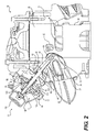
Figure 2 is a partial cross-sectional view of a cylinder block, a cylinder head and one of the exhaust valve assemblies of the engine ofFig. 1 ; -
Figure 3 is a schematic illustration of a pressure control system of the exhaust valve assemblies of the engine ofFig. 1 ; -
Figure 4A is a front elevation view of one of the exhaust valve assemblies of the engine ofFig. 1 with a first valve part, a second valve part and auxiliary valves in flow restricting positions; -
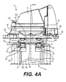
Figure 4B is a cross-sectional view of the exhaust valve assembly ofFig. 4A taken throughline 4B-4B ofFig. 4A ; -
Figure 4C is a partial cross-sectional view of the exhaust valve assembly in the position shown inFig. 4A shown on the engine ofFig. 1 ; -
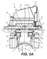
Figure 5A is a front elevation view the exhaust valve assembly ofFig. 4A with the first valve part in an intermediate position and the second valve part and the auxiliary valves in flow restricting positions; -
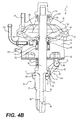
Figure 5B is a cross-sectional view of the exhaust valve assembly ofFig. 5A taken throughline 5B-5B ofFig. 5A ; -
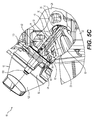
Figure 5C is a partial cross-sectional view of the exhaust valve assembly in the position shown inFig. 5A shown on the engine ofFig. 1 ; -
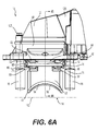
Figure 6A is a front elevation view the exhaust valve assembly ofFig. 4A with the first valve part, the second valve part and the auxiliary valves in full flow positions; -
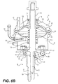
Figure 6B is a cross-sectional view of the exhaust valve assembly ofFig. 6A taken throughline 6B-6B ofFig. 6A ; -
Figure 6C is a partial cross-sectional view of the exhaust valve assembly in the position shown inFig. 6A shown on the engine ofFig. 1 ; and -
Figure 7 is a cross-sectional view of a portion of an alternative implementation of an exhaust valve assembly having an alternative implementation of a valve actuator. - An
exhaust valve assembly 10 has avalve actuator 12, a two-part valve 14 connected to theactuator 12 and auxiliary valves 16 (Fig. 4A ) connected to thevalve 14. A two-stroke engine 18 (Fig. 1 ) has two such exhaust valve assemblies 10 (only one being shown). It should be understood that the term "two-stroke engine" includes an engine having at least one cylinder. Theengine 18 comprises acrankcase 20 and acylinder block 22 connected to thecrankcase 20. Two cylinders 24 (only one being shown), defined in thecylinder block 22, each have amain exhaust port 26. Eachmain exhaust port 26 communicates with acorresponding exhaust passage 28.Auxiliary exhaust ports 30 are disposed on each side of eachmain exhaust port 26 so as to be symmetrical to themain exhaust port 26. Theauxiliary exhaust ports 30 are connected to theircorresponding exhaust passages 28 by way ofauxiliary passages 32. Two admission ports 34 (one per cylinder 24) are defined in thecylinder block 22. Thecrankcase 20 has two internal chambers 36 (one per cylinder) communicating with theircorresponding admission ports 34. Acrankshaft 38 is disposed in theinternal chambers 36 of thecrankcase 20. Twopistons 40 are connected to thecrankshaft 38 via connectingrods 42 and reciprocate in theircorresponding cylinders 24 during operation of theengine 18. Thepistons 40 are adapted to open or close themain exhaust ports 26, theauxiliary exhaust ports 30 and transferports 44. It is contemplated that theengine 18 could have only one or more than twocylinders 24. It should be understood that in this case, theengine 18 would have a number of components, such aspistons 40, corresponding to the number ofcylinders 24. - For simplicity, explanations will now be provided for one of the
cylinders 24 and its associated components. It should be understood that these explanations also apply to theother cylinder 24 and its associated components. - When the
engine 18 is operating at low or medium speeds, themain exhaust port 26 and theauxiliary exhaust ports 30 should not be exposed prematurely by thepiston 40, as the latter moves downwardly. Such a premature exposure of themain exhaust port 26 and theauxiliary exhaust ports 30 is prevented by thevalve 14. Thevalve 14 is slidably mounted in aguide channel 46 having a longitudinal direction that is approximately radial with respect to thecylinder 24 and extends at an acute angle to the axis of themain exhaust passage 26. Auxiliary guide channels (not shown) are provided parallel to theguide channel 46 in the area of theauxiliary passages 32 to receive theauxiliary valves 16. - Turning to
Figs. 4A to 4C , the two-part valve 14 will now be described. The two-part valve 14 includes afirst valve part 50 and asecond valve part 52. Thefirst valve part 50 *and thesecond valve part 52 each have anedge 54, 56 (Fig. 5A ) respectively, shaped so as to match the shape of thecylinder 12. In operation, as inFig. 4C , thesecond valve part 52 is supported and is disposed above thefirst valve part 50. Thefirst valve part 50 has an integrally formedconnector 58 which connects thefirst valve part 50 to theactuator 12. Thesecond valve part 52 has two pairs offingers 60, the lower ones of which are engaged by thefirst valve part 50 as thefirst valve part 50 is moved to a full flow position, as described in greater detail below. A pair ofsprings 62 is provided between thesecond valve part 52 and a bottom of thevalve actuator 12. - As mentioned above, the
exhaust valve assembly 10 also hasauxiliary valves 16 for restricting the flow of exhaust gases in theauxiliary exhaust passages 32. Theauxiliary valves 16 are separate from and movably connected to the two-part valve 14 via alever 64. Thelever 64 has twoarms 66 that are connected to each other at one end by ashaft 68. Thearms 66 have a generally obtuse V-shape.Shafts 70 extend inwardly from the corners of the V-shapedarms 66. Eachshaft 70 has abushing 71 disposed around it. Thebushing 71 has a generally rectangular outer perimeter. Eachbushing 71 is received between a corresponding pair offingers 60 such that theshafts 70 can pivot inside theirrespective bushings 71 in the space between the twofingers 60 of their corresponding pairs offingers 60.Shafts 72 extend outwardly from the ends of thearms 66 opposite the ends of thearms 66 where theshaft 68 is provided. Eachshaft 72 has abushing 73 disposed around it. Thebushing 73 has a generally rectangular outer perimeter. Thebushings 73 are received in oblong apertures 74 defined in the upper ends of theauxiliary valves 16. In the present implementation, a distance from thecentral axis 76 of theshaft 68 to thecentral axes 78 of theshafts 70 is greater than a distance from thecentral axes 78 of theshafts 70 to thecentral axes 80 of theshafts 72. Also, in the present implementation the angle between a line passing through thecentral axis 76 of theshaft 68 and thecentral axes 78 of theshafts 70 and a line passing through thecentral axes 78 of theshafts 70 and thecentral axes 80 of theshafts 72 is between 140 degrees and 150 degrees, but other angles are contemplated. -
Posts 82 extend from a bottom of theactuator 12. Theposts 82 each have an arcuate lower surface against which theshaft 68 abuts. As a result, when thesecond valve part 52 moves from its flow restricting position to its full flow position, theshafts 70 move with thesecond valve part 52. This movement of theshafts 70 causes thelever 64 to pivot about thecentral axis 76 of theshaft 68, thereby moving theauxiliary valves 16 from their flow restricting positions to their full flow positions as will be described in greater detail below. - The
valve actuator 12 will now be described with respect toFig. 4B . Thevalve actuator 12 has avalve housing 90. Adiaphragm 92 has anouter lip 94 received in a recess defined in thevalve housing 90. Apressure chamber wall 96 is connected to thevalve housing 90 by fasteners (similar tofasteners 98 of the embodiment shown inFig. 7 ). Thepressure chamber wall 96 also has a recess that receives theouter lip 94 of thediaphragm 92. As a result, thediaphragm 92 is securely held between thevalve housing 90 and thepressure chamber wall 96. The surfaces of thevalve housing 90 and thepressure chamber wall 96 facing thediaphragm 92 are concave. Thediaphragm 92 and thepressure chamber wall 96 define therebetween anupper pressure chamber 100 which has a variable volume. Thediaphragm 92 and thevalve housing 90 define therebetween alower pressure chamber 102 which has a variable volume. - The
connector 58 of thefirst valve part 50 passes through thevalve housing 90, thediaphragm 92 and thepressure chamber wall 96. Aring 104 is provided around theconnector 58. Asleeve 106 is disposed over the top portion of theconnector 58. Thesleeve 106 has internal threads in a top portion thereof and the connector has corresponding external threads on a top portion thereof. Accordingly, thesleeve 106 is retained on theconnector 58 by screwing thesleeve 106 onto theconnector 58. The bottom of thering 104 abuts a shoulder defined by theconnector 58 and the top of thering 104 abuts the bottom end of thesleeve 106. As such thering 104 cannot move along the length of theconnector 58. Thering 104 has a groove receiving aninner lip 108 of thediaphragm 92. As a result, theconnector 58 is connected to thediaphragm 92 so as to move therewith. - A
ring 110 and asealing ring 112 are disposed between thevalve housing 90 and theconnector 58 to guide theconnector 58 as it moves with thediaphragm 92 and to prevent exhaust gases from entering thelower pressure chamber 102 from theguide channel 46. Aring 114 and asealing ring 116 are disposed between thepressure chamber wall 96 and thesleeve 106 to guide theconnector 58 as it moves with thediaphragm 92 and to prevent gases from entering or exiting theupper pressure chamber 100 via the passage defined in thepressure chamber wall 96 for theconnector 58. - A
spring 118 is disposed inside thelower pressure chamber 102 around theconnector 58 between therings spring 118 biases thefirst valve part 50 toward an intermediate position, shown inFigs. 5A to 5C , described in greater detail below. It is contemplated that thespring 118 could be located elsewhere and still bias thefirst valve part 50 toward the intermediate position, such as between thefirst valve part 50 and a bottom of thevalve housing 90. It is also contemplated that thespring 118 could be omitted completely and that thediaphragm 92 could be self-biasing so as to bias thefirst valve part 50 toward the intermediate position, by properly shaping thediaphragm 92 and by making it out of an appropriate material. It is also contemplated that thespring 118 could be omitted and that thediaphragm 92 could not be self-biasing. - A cover 120 (
Fig. 4A ) is connected to thevalve housing 90 bybolts 122 to enclose thepressure chamber wall 96 anddiaphragm 92 assembly therebetween. Thevalve housing 90 is connected to thecylinder block 22 via bolts (not shown). A seal 124 (Fig. 2 ) is disposed between thevalve housing 90 and thecylinder block 22 to prevent exhaust gases from leaving theexhaust passage 28 via theguide channel 46. A passage 126 (Fig. 4B ) defined in thepressure chamber wall 96 fluidly communicates theupper pressure chamber 100 with at least one pressure source, via a pressure control device, as described below. A passage 128 (Fig. 4C ) defined in thevalve housing 90 fluidly communicates thelower pressure chamber 102 with at least one pressure source, via a pressure control device, as described below. Apipe 130 is connected to thepassage 128. It is contemplated that a port could be provided in thecover 120 to ventilate the volume between thepressure chamber wall 96 and thecover 120. -
Fig. 3 illustrates one possible implementation of a pressure control device for fluidly communicating thepressure chambers valve actuators 12 of theengine 18 with a plurality of pressure sources. When no suffix is provided, reference is being made to the elements associated with bothcylinders 24. During operation of theengine 18, positive and negative pressures are created inside thecrankcase chambers 36. As apiston 40 moves down, pressure inside its correspondingcrankcase chamber 36 increases to create a positive pressure in thischamber 36. As apiston 40 moves up, pressure inside its correspondingcrankcase chamber 36 decreases to create a negative pressure. It is contemplated that in a turbocharged engine, the pressure inside acrankcase chamber 36 as its correspondingpiston 40 moves up could still be a positive pressure, but this positive pressure would be less than the positive pressure created when thepiston 40 moves down. It should be understood that when one of thecrankcase chambers 36 has a positive pressure inside of it, the other of thecrankcase chambers 36 has a negative pressure inside of it. - For purposes of explanation of
Fig. 3 , the reference numerals of elements associated with one of the twocylinders 24 are followed by the suffix A while the reference numerals of elements associated with the other one of the twocylinders 24 are followed by the suffix B.A control valve 132 fluidly communicates with the pressure chambers 100A, 100B via feed lines 134A, 134B respectively. The feed lines 134 are connected to thepassages 126 defined in thepressure chamber walls 96. Acontrol valve 136 fluidly communicates with the pressure chambers 102A, 102B via feed lines 138A, 138B respectively. The feed lines 138 are connected to thepipes 130. Afeed line 140 fluidly communicates with thecontrol valves control valves accumulator chamber 142 fluidly communicates with thefeed line 140 to store pressurized air. Theaccumulator chamber 142 helps maintain a more even pressure inside thefeed line 140. Afeed line 144 is fluidly connected to thecontrol valves control valves feed line 146 fluidly communicates the crankcase chamber 36A with thefeed line 140. A one-way valve 148 only permits a positive pressure to be supplied to thefeed line 140 from thefeed line 146. Afeed line 150 fluidly communicates thefeed line 146 with thefeed line 144. A one-way valve 152 only permits a negative pressure to be supplied to thefeed line 144 from thefeed line 150. Afeed line 154 fluidly communicates the crankcase chamber 36B with thefeed line 144. A one-way valve 156 only permits a negative pressure to be supplied to thefeed line 144 from thefeed line 154. Afeed line 158 fluidly communicates thefeed line 154 with thefeed line 140. A one-way valve 160 only permits a positive pressure to be supplied to thefeed line 140 from thefeed line 158. - As a result of the above arrangement, when there is a positive pressure inside the crankcase chamber 36A and a negative pressure inside the crankcase chamber 36B, the
valve 148 opens to supply the positive pressure from the crankcase chamber 36A to thefeed line 140, thevalve 156 opens to supply the negative pressure from the crankcase chamber 36B to thefeed line 144, thevalve 152 closes to prevent the positive pressure from the crankcase chamber 36A from being supplied to thefeed line 144, and thevalve 160 closes to prevent the negative pressure from the crankcase chamber 36B from being supplied to thefeed line 140. Similarly, when there is a negative pressure inside the crankcase chamber 36A and a positive pressure inside the crankcase chamber 36B, thevalve 152 opens to supply the negative pressure from the crankcase chamber 36A to thefeed line 144, thevalve 160 opens to supply the positive pressure from the crankcase chamber 36B to thefeed line 140, thevalve 148 closes to prevent the negative pressure from the crankcase chamber 36A from being supplied to thefeed line 140, and thevalve 156 closes to prevent the positive pressure from the crankcase chamber 36B from being supplied to thefeed line 144. - By selectively opening and closing the
control valve 132, it is thus possible to supply one of a positive pressure and a negative pressure to thepressure chambers 100 of thevalve actuators 12. Similarly, by selectively opening and closing thecontrol valve 136, it is thus possible to supply one of a positive pressure and a negative pressure to thepressure chambers 102 of thevalve actuators 12. By cycling the opening and closing of thecontrol valves pressure chambers pressure chambers pressure chambers valves valves valve assemblies 10. It is contemplated that the electronic control unit could also determine which pressure is to be supplied to thepressure chambers engine 18 or of components associated with theengine 18, such as, for example, a degree of throttle opening or a rate of acceleration of theengine 18 or a combination of two or more of the engine speed, the degree of throttle opening, the rate of acceleration. - Other pressure control devices are contemplated. For example, the one-way valves could be replaced electronically controlled valves. In another example, the
feed lines way valves feed line 140 is only supplied with positive pressure from the crankcase chamber 36A and thefeed line 144 is only supplied with negative pressure from the crankcase chamber 36B. In another example, thecontrol valves feed line 140 to supply positive pressure to the pressure chambers 100A, 100B or to the pressure chambers 102A, 102B and a control valve fluidly communicating with thefeed line 144 to supply negative pressure to the pressure chambers 100A, 100B or to the pressure chambers 102A, 102B. It is also contemplated that the pressures supplied to thepressure chambers crankcase chambers 26. For example, a compressor could be used to supply the positive pressure and a vacuum pump could be used to supply the negative pressure. In another example, a compressor is also used to supply the positive pressure and, instead of supplying a negative pressure, the pressure chambers can be selectively communicated with the atmosphere to be supplied with ambient pressure. - The operation of one of the
valve assemblies 10 will now be described in association withFigs. 4A to 6C .Line 162 inFigs. 4A ,5A and6A is a line passing through the points where the ends of theedge 54 of thefirst valve part 50 meet thecylinder 24 when thefirst valve part 50 is in its flow restricting position shown inFig. 4A .Line 162 has been added simply to illustrate the movement of thevalves cylinder 24. - As previously mentioned, at low engine speeds, it is desirable to restrict the flow of the exhaust gases through the
exhaust port 26 andauxiliary exhaust ports 30. Thus, at low engine speeds, thevalve 14 is moved to the position shown inFigs. 4A to 4C . To move thevalve 14 to this position, a positive pressure is supplied to thepressure chamber 100 and a negative pressure is supplied to thepressure chamber 102. The pressure difference between thepressure chambers spring 118. This causes thespring 118 to be in compression and thediaphragm 92 moves thefirst valve part 50 in a flow restricting position in theexhaust port 26. Thesecond valve part 52 is held in a flow restricting position by the bias ofsprings 62. Theauxiliary valves 16 which move with thesecond valve part 52 via thelever 64 are also held in their flow restricting positions in theauxiliary exhaust passages 30. - At medium engine speeds, it is desirable to restrict the flow of the exhaust gases through the
exhaust port 26, but to a lesser degree than at low engine speeds. It has also been found that it is desirable to restrict the flow of exhaust gases through theauxiliary exhaust ports 30 to the same degree as at low engine speeds. Thus, at medium engine speeds, thevalve 14 is moved to the position shown inFigs. 5A to 5C . To move thevalve 14 to this position, a pressure intermediate the positive and negative pressures is supplied to thepressure chambers pressure chambers spring 118 and thediaphragm 92 is moved by thespring 118 to the position shown inFig. 5B . In this position, thespring 118 is slightly compressed due to the bias applied bysprings 62 on thefirst valve part 50 via thelower fingers 60 of thesecond valve part 52. Thediaphragm 92 moves thefirst valve part 50 in an intermediate position in theexhaust port 26. The intermediate position is intermediate the full flow position (Fig. 6A to 6C ) and the flow restricting position (Fig. 4A to 4C ) of thefirst valve part 50. Thesecond valve part 52 is held in its flow restricting position by the bias ofsprings 62. As such, theauxiliary valves 16 are also held in their flow restricting positions in theauxiliary exhaust passages 30. As the position of thediaphragm 92 is determined by the difference in pressures between thepressure chambers diaphragm 92 shown inFig. 5B could also be achieved by supplying the positive pressure to bothpressure chambers pressures chambers pressure chambers diaphragm 92 shown inFig. 5B , the pressures inside thepressure chambers pressure chambers spring 118. - At high engine speeds, it is desirable that the exhaust gases flow freely through the
exhaust port 26 andauxiliary exhaust ports 30. Thus, at high engine speeds, thevalve 14 is moved to the position shown inFigs. 6A to 6C . To move thevalve 14 to this position, a negative pressure is supplied to thepressure chamber 100 and a positive pressure is supplied to thepressure chamber 102. As a result of the pressure difference between thepressure chambers diaphragm 92 moves to the position shown inFig. 6B . This causes thespring 118 to be in extension. Thediaphragm 92 moves thefirst valve part 50 in a full flow position where it is withdrawn from theexhaust port 26. As it is moved to its full flow position, thefirst valve part 50 pushes against thelower fingers 60 of thesecond valve part 52 and moves thesecond valve part 52 to a full flow position where it is withdrawn from theexhaust port 26. When thesecond valve part 52 is in its full flow position thesprings 62 are in compression. As thesecond valve part 52 moves to its full flow position, thefingers 60 lift theshafts 70 of thelever 64 with thesecond valve part 52. As a result, since theshaft 68 abuts theposts 82, thelever 64 pivots about thecentral axis 76 of theshaft 68 thereby causing theauxiliary valves 16 to move to full flow positions where they are withdrawn from theauxiliary exhaust ports 30. - The ranges of engine speeds corresponding to low, medium and high engine speeds providing the above described valve positions depend on the specific configuration of the engine and its associated components and on the desired performance characteristics of the engine.
- Due to the geometry of the
arms 66 of thelever 64, the distance travelled by theauxiliary exhaust valves 16 between their flow restricting positions shown inFigs. 4A to 4C and5A to 5C and their full flow positions shown inFigs. 6A to 6C is greater than the distance travelled by thefirst valve part 50 between its flow restricting position shown inFigs. 4A to 4C and its full flow position shown inFigs. 6A to 6C . Therefore, for implementations having equivalent displacement of thefirst valve part 50, since theauxiliary exhaust valves 16 in the implementation described above can be displaced by a greater amount than if they were connected to thefirst valve part 50 to move therewith, as in United States Patent No.7,484,482 for example, theexhaust ports 30 andexhaust passages 32 can have a greater height for the same dimension ofauxiliary valves 16 than in implementations where theauxiliary valves 16 are connected to thefirst valve part 50 to move therewith. - Turning now to
Fig. 7 , an exhaust valve assembly 10' will be described. The exhaust valve assembly 10' has a valve actuator 12', a two-part valve 14' connected to theactuator 12 and auxiliary valves 16 (not shown in this implementation) connected to the valve 14'. Theauxiliary valves 16 are connected to the valve 14' in the same manner as theauxiliary valves 16 are connected to thevalve 14 in theexhaust valve assembly 10 described above. The valve 14' is the same as thevalve 14 described above except that theconnector 58 has been replaced by a connector 58'. The valve actuator 12' moves the valve 14' and theauxiliary valves 16 between the various positions illustrated inFigs. 4A to 6C and described above for theexhaust valve assembly 10. For simplicity, features of the exhaust valve assembly 10' that are similar to those of theexhaust valve assembly 10 described above have been labeled with the same reference numerals and will not be described again. - The connector 58' has a
peripheral groove 164. The diaphragm 92' defines aninner sleeve 166 inside which the connector 58' is received. Thesleeve 166 defines aprotrusion 168 that is received in theperipheral groove 164 of the connector 58' to secure the diaphragm 92' to the connector 58'. Aspring clip 170 is disposed around the upper part of thesleeve 166 to further secure thesleeve 166 to the connector 58' and to prevent fluid present in thepressure chambers sleeve 166 and the connector 58'. - The diaphragm 92' has an outer lip 94' and an
outer lip 172 disposed radially inwardly of the outer lip 94'. Theouter lips 94', 172 are held between the valve housing 90' and the pressure chamber wall 96'. Acircular passage 174 is defined between theouter lips 94', 172 and the top surface of the valve housing 90'.Apertures 176 are defined around the portion of the diaphragm 92' disposed radially between theouter lips 94', 172 and fluidly communicate with thecircular passage 174.Apertures 178 are defined between theouter lip 172 and the pressure chamber wall 96' and fluidly communicate thepressure chamber 102 with theapertures 176. Apassage 180 is defined in the valve housing 90'. Thepassage 180 is selectively connected to positive pressure and negative pressure sources via the pressure control device described above with respect toFig. 3 for example. Thepassage 180 supplies pressure to thecircular passage 174, which is then supplied to thepressure chamber 102 via theapertures - A
cap 182 having aflange 184 is screwed onto the end of the connector 58' that is disposed outside of thepressure chamber 102. Avalve connecting member 186 is connected to thecap 182 by anut 188 such that thevalve connecting member 186 is held between thenut 188 and theflange 184. Thevalve connecting member 186 is similarly connected to an adjacent exhaust valve assembly 10'. Thevalve connecting member 186 is similar to the valve connecting member described in United States Patent No.7,762,220 B2, issued July 27, 2010 . It is contemplated that thevalve connecting member 186, thecap 182 and thenut 188 could be omitted. It is also contemplated that a valve connecting member similar to thevalve connecting member 186 could be provided to connect two adjacentexhaust valve assemblies 10. - Modifications and improvements to the above-described implementations of the present technology may become apparent to those skilled in the art. The foregoing description is intended to be exemplary rather than limiting.
Claims (15)
- An exhaust valve assembly (10) for a two-stroke internal combustion engine (18) comprising:a valve actuator (12) having a first pressure chamber (100) and a second pressure chamber (102),the first pressure chamber (100) being adapted for selectively receiving one of a first pressure and a second pressure,the second pressure chamber (102) being adapted for selectively receiving one of the first pressure and the second pressure,the first pressure being higher than the second pressure; anda valve (14) operatively connected to the valve actuator (12), the valve actuator (12) moving the valve (14) between at least a first valve position and a second valve position,the valve actuator (12) moving the valve (14) to the first valve position when the first pressure is supplied to the first pressure chamber (100) and the second pressure is supplied to the second pressure chamber (102), andthe valve actuator (12) moving the valve (14) to the second valve position when the second pressure is supplied to the first pressure chamber (100) and the first pressure is supplied to the second pressure chamber (102).
- The exhaust valve assembly (10) of claim 1, wherein the valve actuator (12) moves the valve (14) between the first valve position, the second valve position and a third valve position, the third valve position being intermediate the first and second valve positions; and
wherein the valve actuator (12) moves the valve (14) to the third valve position when pressures supplied to the first pressure chamber (100) and the second pressure chamber (102) are equal or substantially equal. - The exhaust valve assembly (10) of claim 1, wherein:the valve actuator (12) comprises a diaphragm (92) separating the first pressure chamber (100) from the second pressure chamber (102);the diaphragm (92) being movable between a first diaphragm position and a second diaphragm position;the diaphragm (92) being in the first diaphragm position when the first pressure is supplied to the first pressure chamber (100) and the second pressure is supplied to the second pressure chamber (102);the diaphragm (92) being in the second diaphragm position when the second pressure is supplied to the first pressure chamber (100) and the first pressure is supplied to the second pressure chamber (102);the valve (14) being in the first valve position when the diaphragm (92) is in the first diaphragm position;the valve (14) being in the second valve position when the diaphragm (92) is in the second diaphragm position.
- The exhaust valve assembly (10) of claim 3, further comprising a spring (118) biasing the valve (14) toward a third valve position, the third valve position being intermediate the first and second valve positions.
- The exhaust valve assembly (10) of claim 4, wherein the spring (118) biases the diaphragm (92) toward a third diaphragm position, the third diaphragm position being intermediate the first and second diaphragm positions, the valve (14) being in the third valve position when the diaphragm (92) is in the third diaphragm position.
- The exhaust valve assembly (10) of any one of claims 3 to 5, wherein the valve actuator (12) further comprises:a valve housing (90) connected to the diaphragm (92), the second pressure chamber (102) being defined between the valve housing (90) and the diaphragm (92), the valve housing (90) being adapted to connect the valve actuator (12) to the engine (18); anda pressure chamber wall (96) connected to the diaphragm (92), the first pressure chamber (100) being defined between the pressure chamber wall (96) and the diaphragm (92).
- The exhaust valve assembly (10) of any one of claims 1 to 6, further comprising:a first control valve (132) fluidly communicating with the first pressure chamber (100);a second control valve (136) fluidly communicating with the second pressure chamber (102);a first feed line(140) fluidly communicating with the first and second control valves (132, 136) for supplying the first pressure to the first and second control valves (132, 136); anda second feed line (144) fluidly communicating with the first and second control valves (132, 136) for supplying the second pressure to the first and second control valves (132, 136);the first control valve (132) selectively fluidly communicating the first pressure chamber (100) with one of the first and second feed lines (140, 144); andthe second control valve (136) selectively fluidly communicating the second pressure chamber (102) with one of the first and second feed lines (140, 144).
- The exhaust valve assembly (10) of claim 7, further comprising an accumulator chamber (142) fluidly communicating with the first feed line (140).
- The exhaust valve assembly (10) of claim 7 or 8, wherein:the first control valve (132) alternatively fluidly communicates the first pressure chamber (100) with the first and second feed lines (140, 144) to have a third pressure in the first pressure chamber (100);the second control valve (136) alternatively fluidly communicates the second pressure chamber (102) with the first and second feed lines (140, 144) to have the third pressure in the second pressure chamber (102);the third pressure is intermediate the first and second pressures;the valve actuator (12) moving the valve (14) to a third position when the third pressure is provided in the first and second pressure chambers (100, 102); andthe third position being intermediate the first and second positions.
- An internal combustion engine (18) comprising:a crankcase (20) defining a crankcase chamber (36);a crankshaft (38) disposed in the crankcase (20);a cylinder block (22) connected to the crankcase (20), the cylinder block (22) having an exhaust passage (28);a cylinder (24) disposed in the cylinder block (22);a piston (40) movably disposed within the cylinder (24) and being operatively connected to the crankshaft (38); andthe valve assembly (10) of any one of claims 1 to 9 connected to the cylinder block (22);wherein in the first valve position, the valve (14) extends in the exhaust passage (28) and, in the second valve position, the valve (14) is withdrawn from the exhaust passage (28).
- The engine (18) of claim 10, wherein:the first and second pressure chambers (100, 102) selectively fluidly communicate with the crankcase chamber (36);the first pressure is a positive pressure and the second pressure is a negative pressure;the crankcase chamber (36) selectively supplying the positive pressure to at least one of the first and second pressure chambers (100, 102) as the piston (40) moves toward the crankcase (20); andthe crankcase chamber (36) selectively supplying the negative pressure to at least one of the first and second pressure chambers (100, 102) as the piston (40) moves away from the crankcase (20).
- The engine (18) of claim 11, further comprising:a first one-way valve (148, 160) permitting the positive pressure to be selectively supplied to at least one of the first and second pressure chambers (100, 102) and preventing the negative pressure to be selectively supplied to at least one of the first and second pressure chambers (100, 102); anda second one-way valve (152, 156) permitting the negative pressure to be selectively supplied to at least one of the first and second pressure chambers (100, 102) and preventing the positive pressure to be selectively supplied to at least one of the first and second pressure chambers (100, 102).
- A method of operating an exhaust valve assembly (10) of a two-stroke internal combustion engine (18), the valve assembly (10) including: a valve actuator (12) having a first pressure chamber (100) and a second pressure chamber (102), and a valve (14) operatively connected to the valve actuator (12), the method comprising:moving the valve (14) to a first valve position by supplying a first pressure to the first pressure chamber (100) and a second pressure to the second pressure chamber (102); andmoving the valve (14) to a second valve position by supplying the second pressure to the first pressure chamber (100) and the first pressure to the second pressure chamber (102), the first pressure being higher than the second pressure.
- The method of claim 13, further comprising moving the valve (14) to a third valve position by supplying equal or substantially equal pressures to the first pressure chamber (100) and the second pressure chamber (102), the third valve position being intermediate the first and second valve positions.
- The method of claim 14, further comprising biasing the valve (14) toward the third valve position using a spring (118).
Applications Claiming Priority (1)
| Application Number | Priority Date | Filing Date | Title |
|---|---|---|---|
| US14/448,314 US9341092B2 (en) | 2014-07-31 | 2014-07-31 | Exhaust valve assembly for a two-stroke internal combustion engine |
Publications (3)
| Publication Number | Publication Date |
|---|---|
| EP2987982A2 true EP2987982A2 (en) | 2016-02-24 |
| EP2987982A3 EP2987982A3 (en) | 2016-03-09 |
| EP2987982B1 EP2987982B1 (en) | 2017-11-08 |
Family
ID=51900282
Family Applications (1)
| Application Number | Title | Priority Date | Filing Date |
|---|---|---|---|
| EP14193318.4A Active EP2987982B1 (en) | 2014-07-31 | 2014-11-14 | Exhaust valve assembly for a two-stroke internal combustion engine |
Country Status (2)
| Country | Link |
|---|---|
| US (1) | US9341092B2 (en) |
| EP (1) | EP2987982B1 (en) |
Families Citing this family (2)
| Publication number | Priority date | Publication date | Assignee | Title |
|---|---|---|---|---|
| EP3199787B1 (en) | 2016-01-31 | 2019-02-13 | BRP-Rotax GmbH & Co. KG | Exhaust valve assembly for a two-stroke internal combustion engine |
| US11396853B2 (en) | 2019-06-28 | 2022-07-26 | Brp Us Inc. | Exhaust valve, exhaust valve assembly and exhaust valve system for two-stroke internal combustion engines, two-stroke internal combustion engine having same and method for cleaning an exhaust valve |
Citations (2)
| Publication number | Priority date | Publication date | Assignee | Title |
|---|---|---|---|---|
| US7484482B1 (en) | 2007-01-22 | 2009-02-03 | Brp-Rotax Gmbh & Co. Kg | Valve assembly for a two-stroke engine |
| US7762220B2 (en) | 2007-09-28 | 2010-07-27 | Brp-Powertrain Gmbh & Co Kg | Valve assembly for a two-stroke engine |
Family Cites Families (11)
| Publication number | Priority date | Publication date | Assignee | Title |
|---|---|---|---|---|
| JPS5844847B2 (en) | 1975-12-25 | 1983-10-05 | 株式会社日本自動車部品総合研究所 | Ninen Kikanyou Heikigasujiyoukasouchi |
| US5873334A (en) * | 1997-10-22 | 1999-02-23 | Polaris Industries Inc. | Exhaust valve system for two-cycle engines |
| CA2223770A1 (en) | 1997-12-05 | 1999-06-05 | Bombardier Inc. | Valve assembly using pressurized medium for controlling operating conditions of a two-stroke engine |
| US6189494B1 (en) * | 1998-05-14 | 2001-02-20 | Fuji Jukogyo Kabushiki Kaisha | Exhaust timing control apparatus for two-cycle engines |
| US6158215A (en) * | 1998-11-12 | 2000-12-12 | Polaris Industries Inc. | Varible exhaust resonance chamber valve system for two-cycle engines |
| US6216648B1 (en) | 1999-05-14 | 2001-04-17 | Arctic Cat, Inc. | Internal combustion engine with pneumatically controlled variable exhaust valve |
| US6352056B1 (en) | 2000-06-23 | 2002-03-05 | Brunswick Corporation | Exhaust valve actuator for a two cycle engine |
| US6371156B1 (en) | 2000-08-10 | 2002-04-16 | Fisher Controls International, Inc. | No-bleed pilot for pressure regulating valve |
| US7213544B2 (en) * | 2004-01-30 | 2007-05-08 | Brp-Rotax Gmbh & Co. Kg | Exhaust-outlet control for 2-stroke engine |
| JP2006170026A (en) | 2004-12-14 | 2006-06-29 | Aisin Seiki Co Ltd | Valve timing control device for internal combustion engine |
| DE102007020579A1 (en) | 2007-05-02 | 2008-11-06 | Ktm-Sportmotorcycle Ag | Two-stroke internal combustion engine |
-
2014
- 2014-07-31 US US14/448,314 patent/US9341092B2/en active Active
- 2014-11-14 EP EP14193318.4A patent/EP2987982B1/en active Active
Patent Citations (2)
| Publication number | Priority date | Publication date | Assignee | Title |
|---|---|---|---|---|
| US7484482B1 (en) | 2007-01-22 | 2009-02-03 | Brp-Rotax Gmbh & Co. Kg | Valve assembly for a two-stroke engine |
| US7762220B2 (en) | 2007-09-28 | 2010-07-27 | Brp-Powertrain Gmbh & Co Kg | Valve assembly for a two-stroke engine |
Also Published As
| Publication number | Publication date |
|---|---|
| US9341092B2 (en) | 2016-05-17 |
| US20160032793A1 (en) | 2016-02-04 |
| EP2987982B1 (en) | 2017-11-08 |
| EP2987982A3 (en) | 2016-03-09 |
Similar Documents
| Publication | Publication Date | Title |
|---|---|---|
| AU2008259733B2 (en) | Hydroelectric device for closed-loop driving the control jack of a variable compression rate engine | |
| US7762220B2 (en) | Valve assembly for a two-stroke engine | |
| US8151691B2 (en) | Variable compression ratio piston with rate-sensitive response | |
| FI121512B (en) | Piston engine suction valve control arrangement | |
| US8210138B2 (en) | Split-cycle engine with pilot crossover valve | |
| KR970001858A (en) | Multi-stage open-valve device | |
| MX2011008979A (en) | Variable travel valve apparatus for an internal combustion engine. | |
| EP2889465B1 (en) | Exhaust valve assembly for a two-stroke engine | |
| EP2987982B1 (en) | Exhaust valve assembly for a two-stroke internal combustion engine | |
| US7484482B1 (en) | Valve assembly for a two-stroke engine | |
| CN100523461C (en) | Load responding engine | |
| CN107916983A (en) | A kind of charge air cooler automatic bleeder | |
| EP2363579A1 (en) | Oil flow control valve with two check valves | |
| CN107850010B (en) | Multi-plunger cryopump with intake manifold | |
| US20180202469A1 (en) | Hydraulic module for controlling a hydraulic fluid flow of a connecting rod for an internal combustion engine with variable compression and a connecting rod | |
| JP5412570B2 (en) | Fuel pump for turbocharged large two-stroke diesel engines | |
| CN107313856A (en) | Cylinder head, engine and its control method, control module and automobile | |
| JPH0791969B2 (en) | Valve drive for internal combustion engine | |
| JP5234619B2 (en) | Air compressor | |
| US8925502B1 (en) | Hydraulically actuated valve assembly for an engine | |
| CN204357518U (en) | Actuator and electro-hydraulic actuation formula engine valve | |
| RU2472014C2 (en) | Valve unit for two-stroke engine | |
| JPH1144289A (en) | Reciprocating compressor | |
| CN102597457B (en) | A Compensation Device for Variable Compression Ratio Engine | |
| EP3161292B1 (en) | Engine configuration having various displacements |
Legal Events
| Date | Code | Title | Description |
|---|---|---|---|
| PUAL | Search report despatched |
Free format text: ORIGINAL CODE: 0009013 |
|
| PUAI | Public reference made under article 153(3) epc to a published international application that has entered the european phase |
Free format text: ORIGINAL CODE: 0009012 |
|
| AK | Designated contracting states |
Kind code of ref document: A2 Designated state(s): AL AT BE BG CH CY CZ DE DK EE ES FI FR GB GR HR HU IE IS IT LI LT LU LV MC MK MT NL NO PL PT RO RS SE SI SK SM TR |
|
| AX | Request for extension of the european patent |
Extension state: BA ME |
|
| AK | Designated contracting states |
Kind code of ref document: A3 Designated state(s): AL AT BE BG CH CY CZ DE DK EE ES FI FR GB GR HR HU IE IS IT LI LT LU LV MC MK MT NL NO PL PT RO RS SE SI SK SM TR |
|
| AX | Request for extension of the european patent |
Extension state: BA ME |
|
| RIC1 | Information provided on ipc code assigned before grant |
Ipc: F01L 7/12 20060101ALI20160201BHEP Ipc: F02B 25/14 20060101AFI20160201BHEP Ipc: F02D 9/04 20060101ALI20160201BHEP Ipc: F02B 33/30 20060101ALI20160201BHEP Ipc: F02D 13/02 20060101ALI20160201BHEP |
|
| RAP1 | Party data changed (applicant data changed or rights of an application transferred) |
Owner name: BRP-ROTAX GMBH & CO. KG |
|
| 17P | Request for examination filed |
Effective date: 20160908 |
|
| RBV | Designated contracting states (corrected) |
Designated state(s): AL AT BE BG CH CY CZ DE DK EE ES FI FR GB GR HR HU IE IS IT LI LT LU LV MC MK MT NL NO PL PT RO RS SE SI SK SM TR |
|
| 17Q | First examination report despatched |
Effective date: 20161117 |
|
| GRAP | Despatch of communication of intention to grant a patent |
Free format text: ORIGINAL CODE: EPIDOSNIGR1 |
|
| INTG | Intention to grant announced |
Effective date: 20170428 |
|
| GRAS | Grant fee paid |
Free format text: ORIGINAL CODE: EPIDOSNIGR3 |
|
| GRAJ | Information related to disapproval of communication of intention to grant by the applicant or resumption of examination proceedings by the epo deleted |
Free format text: ORIGINAL CODE: EPIDOSDIGR1 |
|
| GRAL | Information related to payment of fee for publishing/printing deleted |
Free format text: ORIGINAL CODE: EPIDOSDIGR3 |
|
| GRAR | Information related to intention to grant a patent recorded |
Free format text: ORIGINAL CODE: EPIDOSNIGR71 |
|
| GRAA | (expected) grant |
Free format text: ORIGINAL CODE: 0009210 |
|
| INTC | Intention to grant announced (deleted) | ||
| AK | Designated contracting states |
Kind code of ref document: B1 Designated state(s): AL AT BE BG CH CY CZ DE DK EE ES FI FR GB GR HR HU IE IS IT LI LT LU LV MC MK MT NL NO PL PT RO RS SE SI SK SM TR |
|
| INTG | Intention to grant announced |
Effective date: 20170929 |
|
| REG | Reference to a national code |
Ref country code: GB Ref legal event code: FG4D |
|
| REG | Reference to a national code |
Ref country code: CH Ref legal event code: EP Ref country code: AT Ref legal event code: REF Ref document number: 944376 Country of ref document: AT Kind code of ref document: T Effective date: 20171115 |
|
| REG | Reference to a national code |
Ref country code: IE Ref legal event code: FG4D |
|
| REG | Reference to a national code |
Ref country code: DE Ref legal event code: R096 Ref document number: 602014016828 Country of ref document: DE |
|
| REG | Reference to a national code |
Ref country code: NL Ref legal event code: MP Effective date: 20171108 |
|
| REG | Reference to a national code |
Ref country code: LT Ref legal event code: MG4D |
|
| PG25 | Lapsed in a contracting state [announced via postgrant information from national office to epo] |
Ref country code: NO Free format text: LAPSE BECAUSE OF FAILURE TO SUBMIT A TRANSLATION OF THE DESCRIPTION OR TO PAY THE FEE WITHIN THE PRESCRIBED TIME-LIMIT Effective date: 20180208 Ref country code: LT Free format text: LAPSE BECAUSE OF FAILURE TO SUBMIT A TRANSLATION OF THE DESCRIPTION OR TO PAY THE FEE WITHIN THE PRESCRIBED TIME-LIMIT Effective date: 20171108 Ref country code: FI Free format text: LAPSE BECAUSE OF FAILURE TO SUBMIT A TRANSLATION OF THE DESCRIPTION OR TO PAY THE FEE WITHIN THE PRESCRIBED TIME-LIMIT Effective date: 20171108 Ref country code: NL Free format text: LAPSE BECAUSE OF FAILURE TO SUBMIT A TRANSLATION OF THE DESCRIPTION OR TO PAY THE FEE WITHIN THE PRESCRIBED TIME-LIMIT Effective date: 20171108 Ref country code: ES Free format text: LAPSE BECAUSE OF FAILURE TO SUBMIT A TRANSLATION OF THE DESCRIPTION OR TO PAY THE FEE WITHIN THE PRESCRIBED TIME-LIMIT Effective date: 20171108 Ref country code: SE Free format text: LAPSE BECAUSE OF FAILURE TO SUBMIT A TRANSLATION OF THE DESCRIPTION OR TO PAY THE FEE WITHIN THE PRESCRIBED TIME-LIMIT Effective date: 20171108 |
|
| PG25 | Lapsed in a contracting state [announced via postgrant information from national office to epo] |
Ref country code: BG Free format text: LAPSE BECAUSE OF FAILURE TO SUBMIT A TRANSLATION OF THE DESCRIPTION OR TO PAY THE FEE WITHIN THE PRESCRIBED TIME-LIMIT Effective date: 20180208 Ref country code: LV Free format text: LAPSE BECAUSE OF FAILURE TO SUBMIT A TRANSLATION OF THE DESCRIPTION OR TO PAY THE FEE WITHIN THE PRESCRIBED TIME-LIMIT Effective date: 20171108 Ref country code: GR Free format text: LAPSE BECAUSE OF FAILURE TO SUBMIT A TRANSLATION OF THE DESCRIPTION OR TO PAY THE FEE WITHIN THE PRESCRIBED TIME-LIMIT Effective date: 20180209 Ref country code: IS Free format text: LAPSE BECAUSE OF FAILURE TO SUBMIT A TRANSLATION OF THE DESCRIPTION OR TO PAY THE FEE WITHIN THE PRESCRIBED TIME-LIMIT Effective date: 20180308 Ref country code: RS Free format text: LAPSE BECAUSE OF FAILURE TO SUBMIT A TRANSLATION OF THE DESCRIPTION OR TO PAY THE FEE WITHIN THE PRESCRIBED TIME-LIMIT Effective date: 20171108 Ref country code: HR Free format text: LAPSE BECAUSE OF FAILURE TO SUBMIT A TRANSLATION OF THE DESCRIPTION OR TO PAY THE FEE WITHIN THE PRESCRIBED TIME-LIMIT Effective date: 20171108 |
|
| PG25 | Lapsed in a contracting state [announced via postgrant information from national office to epo] |
Ref country code: EE Free format text: LAPSE BECAUSE OF FAILURE TO SUBMIT A TRANSLATION OF THE DESCRIPTION OR TO PAY THE FEE WITHIN THE PRESCRIBED TIME-LIMIT Effective date: 20171108 Ref country code: CY Free format text: LAPSE BECAUSE OF FAILURE TO SUBMIT A TRANSLATION OF THE DESCRIPTION OR TO PAY THE FEE WITHIN THE PRESCRIBED TIME-LIMIT Effective date: 20171108 Ref country code: DK Free format text: LAPSE BECAUSE OF FAILURE TO SUBMIT A TRANSLATION OF THE DESCRIPTION OR TO PAY THE FEE WITHIN THE PRESCRIBED TIME-LIMIT Effective date: 20171108 Ref country code: CH Free format text: LAPSE BECAUSE OF NON-PAYMENT OF DUE FEES Effective date: 20171130 Ref country code: LI Free format text: LAPSE BECAUSE OF NON-PAYMENT OF DUE FEES Effective date: 20171130 Ref country code: CZ Free format text: LAPSE BECAUSE OF FAILURE TO SUBMIT A TRANSLATION OF THE DESCRIPTION OR TO PAY THE FEE WITHIN THE PRESCRIBED TIME-LIMIT Effective date: 20171108 Ref country code: SK Free format text: LAPSE BECAUSE OF FAILURE TO SUBMIT A TRANSLATION OF THE DESCRIPTION OR TO PAY THE FEE WITHIN THE PRESCRIBED TIME-LIMIT Effective date: 20171108 |
|
| REG | Reference to a national code |
Ref country code: DE Ref legal event code: R097 Ref document number: 602014016828 Country of ref document: DE |
|
| PG25 | Lapsed in a contracting state [announced via postgrant information from national office to epo] |
Ref country code: PL Free format text: LAPSE BECAUSE OF FAILURE TO SUBMIT A TRANSLATION OF THE DESCRIPTION OR TO PAY THE FEE WITHIN THE PRESCRIBED TIME-LIMIT Effective date: 20171108 Ref country code: SM Free format text: LAPSE BECAUSE OF FAILURE TO SUBMIT A TRANSLATION OF THE DESCRIPTION OR TO PAY THE FEE WITHIN THE PRESCRIBED TIME-LIMIT Effective date: 20171108 Ref country code: RO Free format text: LAPSE BECAUSE OF FAILURE TO SUBMIT A TRANSLATION OF THE DESCRIPTION OR TO PAY THE FEE WITHIN THE PRESCRIBED TIME-LIMIT Effective date: 20171108 Ref country code: LU Free format text: LAPSE BECAUSE OF NON-PAYMENT OF DUE FEES Effective date: 20171114 |
|
| REG | Reference to a national code |
Ref country code: BE Ref legal event code: MM Effective date: 20171130 |
|
| REG | Reference to a national code |
Ref country code: IE Ref legal event code: MM4A |
|
| PLBE | No opposition filed within time limit |
Free format text: ORIGINAL CODE: 0009261 |
|
| STAA | Information on the status of an ep patent application or granted ep patent |
Free format text: STATUS: NO OPPOSITION FILED WITHIN TIME LIMIT |
|
| PG25 | Lapsed in a contracting state [announced via postgrant information from national office to epo] |
Ref country code: MT Free format text: LAPSE BECAUSE OF NON-PAYMENT OF DUE FEES Effective date: 20171114 |
|
| REG | Reference to a national code |
Ref country code: FR Ref legal event code: ST Effective date: 20180907 |
|
| 26N | No opposition filed |
Effective date: 20180809 |
|
| PG25 | Lapsed in a contracting state [announced via postgrant information from national office to epo] |
Ref country code: FR Free format text: LAPSE BECAUSE OF NON-PAYMENT OF DUE FEES Effective date: 20180108 Ref country code: IE Free format text: LAPSE BECAUSE OF NON-PAYMENT OF DUE FEES Effective date: 20171114 |
|
| PG25 | Lapsed in a contracting state [announced via postgrant information from national office to epo] |
Ref country code: SI Free format text: LAPSE BECAUSE OF FAILURE TO SUBMIT A TRANSLATION OF THE DESCRIPTION OR TO PAY THE FEE WITHIN THE PRESCRIBED TIME-LIMIT Effective date: 20171108 Ref country code: BE Free format text: LAPSE BECAUSE OF NON-PAYMENT OF DUE FEES Effective date: 20171130 |
|
| PG25 | Lapsed in a contracting state [announced via postgrant information from national office to epo] |
Ref country code: HU Free format text: LAPSE BECAUSE OF FAILURE TO SUBMIT A TRANSLATION OF THE DESCRIPTION OR TO PAY THE FEE WITHIN THE PRESCRIBED TIME-LIMIT; INVALID AB INITIO Effective date: 20141114 Ref country code: MC Free format text: LAPSE BECAUSE OF FAILURE TO SUBMIT A TRANSLATION OF THE DESCRIPTION OR TO PAY THE FEE WITHIN THE PRESCRIBED TIME-LIMIT Effective date: 20171108 |
|
| GBPC | Gb: european patent ceased through non-payment of renewal fee |
Effective date: 20181114 |
|
| PG25 | Lapsed in a contracting state [announced via postgrant information from national office to epo] |
Ref country code: MK Free format text: LAPSE BECAUSE OF FAILURE TO SUBMIT A TRANSLATION OF THE DESCRIPTION OR TO PAY THE FEE WITHIN THE PRESCRIBED TIME-LIMIT Effective date: 20171108 |
|
| PG25 | Lapsed in a contracting state [announced via postgrant information from national office to epo] |
Ref country code: GB Free format text: LAPSE BECAUSE OF NON-PAYMENT OF DUE FEES Effective date: 20181114 |
|
| PG25 | Lapsed in a contracting state [announced via postgrant information from national office to epo] |
Ref country code: TR Free format text: LAPSE BECAUSE OF FAILURE TO SUBMIT A TRANSLATION OF THE DESCRIPTION OR TO PAY THE FEE WITHIN THE PRESCRIBED TIME-LIMIT Effective date: 20171108 |
|
| PG25 | Lapsed in a contracting state [announced via postgrant information from national office to epo] |
Ref country code: PT Free format text: LAPSE BECAUSE OF FAILURE TO SUBMIT A TRANSLATION OF THE DESCRIPTION OR TO PAY THE FEE WITHIN THE PRESCRIBED TIME-LIMIT Effective date: 20171108 |
|
| REG | Reference to a national code |
Ref country code: AT Ref legal event code: UEP Ref document number: 944376 Country of ref document: AT Kind code of ref document: T Effective date: 20171108 |
|
| PG25 | Lapsed in a contracting state [announced via postgrant information from national office to epo] |
Ref country code: AL Free format text: LAPSE BECAUSE OF FAILURE TO SUBMIT A TRANSLATION OF THE DESCRIPTION OR TO PAY THE FEE WITHIN THE PRESCRIBED TIME-LIMIT Effective date: 20171108 |
|
| PGFP | Annual fee paid to national office [announced via postgrant information from national office to epo] |
Ref country code: DE Payment date: 20251126 Year of fee payment: 12 |
|
| PGFP | Annual fee paid to national office [announced via postgrant information from national office to epo] |
Ref country code: AT Payment date: 20251118 Year of fee payment: 12 |
|
| PGFP | Annual fee paid to national office [announced via postgrant information from national office to epo] |
Ref country code: IT Payment date: 20251121 Year of fee payment: 12 |