EP2987645A2 - Non-pneumatic tire having improved riding comfort - Google Patents
Non-pneumatic tire having improved riding comfort Download PDFInfo
- Publication number
- EP2987645A2 EP2987645A2 EP15179235.5A EP15179235A EP2987645A2 EP 2987645 A2 EP2987645 A2 EP 2987645A2 EP 15179235 A EP15179235 A EP 15179235A EP 2987645 A2 EP2987645 A2 EP 2987645A2
- Authority
- EP
- European Patent Office
- Prior art keywords
- aluminum wheel
- pneumatic tire
- rubber
- vibration isolators
- vibration
- Prior art date
- Legal status (The legal status is an assumption and is not a legal conclusion. Google has not performed a legal analysis and makes no representation as to the accuracy of the status listed.)
- Granted
Links
Images

Classifications
-
- B—PERFORMING OPERATIONS; TRANSPORTING
- B60—VEHICLES IN GENERAL
- B60C—VEHICLE TYRES; TYRE INFLATION; TYRE CHANGING; CONNECTING VALVES TO INFLATABLE ELASTIC BODIES IN GENERAL; DEVICES OR ARRANGEMENTS RELATED TO TYRES
- B60C7/00—Non-inflatable or solid tyres
- B60C7/10—Non-inflatable or solid tyres characterised by means for increasing resiliency
- B60C7/102—Tyres built-up with separate rubber parts
-
- B—PERFORMING OPERATIONS; TRANSPORTING
- B60—VEHICLES IN GENERAL
- B60C—VEHICLE TYRES; TYRE INFLATION; TYRE CHANGING; CONNECTING VALVES TO INFLATABLE ELASTIC BODIES IN GENERAL; DEVICES OR ARRANGEMENTS RELATED TO TYRES
- B60C7/00—Non-inflatable or solid tyres
- B60C7/10—Non-inflatable or solid tyres characterised by means for increasing resiliency
- B60C7/14—Non-inflatable or solid tyres characterised by means for increasing resiliency using springs
-
- B—PERFORMING OPERATIONS; TRANSPORTING
- B60—VEHICLES IN GENERAL
- B60C—VEHICLE TYRES; TYRE INFLATION; TYRE CHANGING; CONNECTING VALVES TO INFLATABLE ELASTIC BODIES IN GENERAL; DEVICES OR ARRANGEMENTS RELATED TO TYRES
- B60C7/00—Non-inflatable or solid tyres
- B60C7/10—Non-inflatable or solid tyres characterised by means for increasing resiliency
- B60C7/107—Non-inflatable or solid tyres characterised by means for increasing resiliency comprising lateral openings
-
- B—PERFORMING OPERATIONS; TRANSPORTING
- B60—VEHICLES IN GENERAL
- B60C—VEHICLE TYRES; TYRE INFLATION; TYRE CHANGING; CONNECTING VALVES TO INFLATABLE ELASTIC BODIES IN GENERAL; DEVICES OR ARRANGEMENTS RELATED TO TYRES
- B60C7/00—Non-inflatable or solid tyres
- B60C7/10—Non-inflatable or solid tyres characterised by means for increasing resiliency
- B60C7/14—Non-inflatable or solid tyres characterised by means for increasing resiliency using springs
- B60C7/146—Non-inflatable or solid tyres characterised by means for increasing resiliency using springs extending substantially radially, e.g. like spokes
-
- B—PERFORMING OPERATIONS; TRANSPORTING
- B60—VEHICLES IN GENERAL
- B60C—VEHICLE TYRES; TYRE INFLATION; TYRE CHANGING; CONNECTING VALVES TO INFLATABLE ELASTIC BODIES IN GENERAL; DEVICES OR ARRANGEMENTS RELATED TO TYRES
- B60C7/00—Non-inflatable or solid tyres
- B60C7/10—Non-inflatable or solid tyres characterised by means for increasing resiliency
- B60C7/14—Non-inflatable or solid tyres characterised by means for increasing resiliency using springs
- B60C7/16—Non-inflatable or solid tyres characterised by means for increasing resiliency using springs of helical or flat coil form
- B60C7/18—Non-inflatable or solid tyres characterised by means for increasing resiliency using springs of helical or flat coil form disposed radially relative to wheel axis
-
- B—PERFORMING OPERATIONS; TRANSPORTING
- B60—VEHICLES IN GENERAL
- B60B—VEHICLE WHEELS; CASTORS; AXLES FOR WHEELS OR CASTORS; INCREASING WHEEL ADHESION
- B60B9/00—Wheels of high resiliency, e.g. with conical interacting pressure-surfaces
- B60B9/26—Wheels of high resiliency, e.g. with conical interacting pressure-surfaces comprising resilient spokes
Definitions
- the present invention relates generally to a non-pneumatic tire and, more particularly, to a non-pneumatic tire that includes vibration isolators between a polyurethane spoke and an aluminum wheel, thereby achieving an excellent vibration isolation effect and also improving the performance of adhesion between the spoke and the wheel.
- Non-pneumatic tires are designed such that a spoke is responsible for the function of air pressure, unlike pneumatic tires.
- Non-pneumatic tires have advantages in that the risk of the puncture, which is a major issue for pneumatic tires, is eliminated and also it is not necessary to maintain air pressure.
- conventional non-pneumatic tires include spoke members arranged between inner and outer cylindrical members at predetermined intervals and within a predetermined angle range, and thus empty spaces are present among the spoke members, with the result that serious vibrations are generated during the running of a vehicle.
- a non-pneumatic tire having a structure in which a spoke made of polyurethane directly comes into contact with an aluminum wheel has been developed.
- the tire primarily isolates impacts, occurring on the surface of the tire that comes into contact with a road surface, by means of a rubber tread, the tire has a disadvantage in that the tire is detrimental to riding comfort because impact force or pressure, generated when the tire comes into contact with a road surface during the rotation of the tire, is transferred from the polyurethane spoke to the wheel.
- At least one embodiment of the present invention is directed to the provision of a non-pneumatic that is capable of reducing the vibration transmissibility between a polyurethane spoke and an aluminum wheel, thereby improving the riding comfort of the tire.
- a non-pneumatic tire including a cylindrical tread configured to come into contact with a road surface, an aluminum wheel configured to form a circumference smaller than that of the tread and concentrically disposed inside the tread, and a polyurethane spoke configured to perform a shock absorbing action while connecting the tread with the aluminum wheel; wherein the aluminum wheel includes a plurality of depressed grooves formed at predetermined intervals along the circumferential surface of the aluminum wheel, and a plurality of vibration isolators made of vibration isolation material is inserted into the grooves.
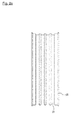
- FIG. 1 is a perspective view of a non-pneumatic tire according to an embodiment of the present invention.
- the non-pneumatic tire according to the present embodiment includes a tread 10 configured to come into contact with a road surface and have a predetermined pattern shape, and an aluminum wheel 20 configured to have a circumference smaller than that of the tread 10 and concentrically disposed inside the tread 10.
- the non-pneumatic tire further includes a spoke 30 configured to providing a shock absorbing action while connecting the tread 10 and the aluminum wheel 20.
- the spoke 30 functions as a shock absorbing part, and is made of polyurethane.
- the present invention is intended to improve the riding comfort of a tire by inserting rubber vibration isolators having a vibration isolation effect between the polyurethane spoke 30 and the aluminum wheel 20.
- the term "isolation of vibrations” used herein refers to all types of techniques for insulating, blocking or isolating a vibration path along which vibrations are transferred from a vibration source to an adjacent mechanical element. More specifically, the term “isolation of vibrations” used herein refers to preventing vibrations, generated by impacts or pressures occurring on the surface of a tire that comes into contact with a road surface, from being transferred to the aluminum wheel 20.
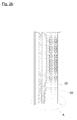
- FIG. 2A is a front view showing a structure in which grooves are formed on an aluminum wheel according to an embodiment of the present invention.
- an aluminum wheel 20 includes a plurality of grooves 21 that are formed on the circumferential surface of the aluminum wheel 20 at predetermined intervals.
- FIG. 2B is a front view showing a structure in which vibration isolators are inserted into the grooves of an aluminum wheel according to an embodiment of the present invention.
- vibration isolators 22 made of vibration isolation material are inserted into grooves 21. These vibration isolators 22 can effectively isolate vibrations generated by impacts or pressures occurring on the surface of a tire that comes into contact with a road surface.
- the present invention is designed such that the aluminum wheel 20 is fabricated in a structure in which the grooves 21 are formed on the circumferential surface of the aluminum wheel 20 and the grooves 21 are filled with the vibration isolators 22, as described above, thereby preventing the performance of the coupling of the aluminum wheel 20 and the spoke 30 from being reduced. That is, in general, to couple the aluminum wheel 20 and the spoke 30, an adhesive is applied onto the circumferential surface of the aluminum wheel 20, and then the aluminum wheel 20 is coupled with the spoke 30.
- depressed stepped grooves 21 are formed on the aluminum wheel 20 and the vibration isolators 22 are inserted into the grooves 21, and thus the sliding friction between the aluminum wheel 20 and the spoke 30 can be reduced, thereby improving the performance of adhesion between the aluminum wheel 20 and the spoke 30.
- grooves 21 are illustrated as being designed to extend along the longitudinal direction of a tire, i.e., the circumferential direction of the tire in FIG. 2A , grooves 21 may be also formed along a tire width direction, that is the direction perpendicular to the circumferential direction of the tire and vibration isolators 22 may be inserted into the grooves 21 in another embodiment of the present invention.
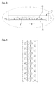
- FIG. 3 is an enlarged view of portion A of FIG. 2B .
- the width w of one groove 21 preferably ranges from 10 to 15% of the overall width of the aluminum wheel 20.
- the vibration isolation effect decreases when the width w is less than 10% of the overall width of the aluminum wheel 20, and the performance of adhesion between the aluminum wheel 20 and the spoke 30 degrades when the width w exceeds 15% of the overall width of the aluminum wheel 20.
- the interval d between the neighboring grooves 21 preferably ranges from 30 to 50% of the width w of the groove 21.
- the interval d is less than 30% of the width w, an area into which the vibration isolator 22 is inserted increases, and thus the performance of adhesion between the wheel 20 and the spoke 30 may degrade.
- the interval d exceeds 50% of the width w, an area in which the vibration isolator 22 is inserted decreases, and thus the vibration isolation effect decreases.
- the thickness h of the grooves 21 preferably ranges from 20 to 50% of the overall thickness H of the widthwise part of the aluminum wheel 20.
- the vibration isolation effect is not sufficient when the thickness h is less than 20% of the overall thickness H of the widthwise part of the aluminum wheel 20, and the strength of the aluminum wheel 20 may decrease and also the weight of the tire may increase when the thickness h exceeds 50% of the overall thickness H of the widthwise part of the aluminum wheel 20.
- the material of the vibration isolators 22 is preferably a material having a soft modulus of elasticity equal to or less than 20% of the modulus of elasticity of polyurethane, i.e., the material of the spoke 30.
- TR 1 K body + 1 K source 1 K body + 1 K iso + 1 K source
- K source is the modulus of elasticity of the polyurethane spoke, and has a value of about 32 Mpa.
- K body is the modulus of elasticity of the aluminum wheel, and has a value of about 76000 Mpa.
- K iso is the modulus of elasticity of insulating rubber used as the vibration isolators, and has a value of about 6 Mpa.
- the modulus of elasticity of the vibration isolators 22 preferably ranges from 1 to 20% of the modulus of elasticity of the polyurethane. When the modulus of elasticity exceeds 20%, the vibration isolation effect that can be achieved by the vibration isolators 22 significantly decreases.
- the vibration isolation effect is calculated in the case where the vibration isolators 22 are applied such that the overall surface area of the vibration isolators 22 corresponds to 50% of the overall surface area of the aluminum wheel 20, a transmissibility reduction effect of about 33% is achieved.
- the vibration isolators 22 are applied such that the overall surface area of the vibration isolators 22 corresponds to 50% or less of the circumferential surface of the aluminum wheel 22, advantages arise in that a vibration isolation effect can be not only achieved but the performance of adhesion between the polyurethane spoke 30 and the aluminum wheel 20 can be also improved.
- the vibration isolation effect increases.
- the material of the vibration isolators 22 that can be used in the embodiments of the present invention may be any soft material as long as the material has a modulus of elasticity equal to or less than 20% of the modulus of elasticity of polyurethane.
- a representative vibration insulating material is vibration-proof rubber.
- the material of the vibration isolators may be one or more selected from the group consisting of butyl rubber, natural rubber, styrene butadiene rubber, styrene butadiene rubber including a maleic acid or a maleic acid derivative, nitrile butadiene rubber, epichlorohydrin rubber, halobutyl rubber, chlorosulfonated polyethylene rubber, chlorinated polyethylene rubber, and brominated polyethylene rubber.
- test examples are used merely to describe the specific examples of the present invention, and the range of protection of the present invention is not limited to these examples.
- Test example 1 measurement of vibration isolation performance of non-pneumatic tire in which vibration isolation rubber has been inserted into aluminum wheel.
- An aluminum wheel 20, such as that shown in FIG. 4 was fabricated by using butyl rubber, used in the inner liner of a tire, as vibration isolators 22.
- the width w of the groove 21 was 16 mm
- the interval d between grooves 21 was 7.5 mm
- the thickness of the groove 21 was 6 mm.
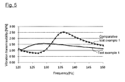
- Input force was applied to a non-pneumatic tire equipped with the aluminum wheel 20 fabricated as described above by applying vibration to the non-pneumatic tire using an impact hammer, and reaction force was measured at the center of the aluminum wheel 20.
- the reaction force was measured with a 6-component load cell sensor mounted on the axial center of the aluminum wheel 20. Vibration isolation performance was measured by calculating the ratio of the input force to the reaction force, and the results of the measurement were plotted on the graph of FIG. 5 .
- Comparative test example 1 measurement of vibration isolation performance of non-pneumatic tire
- Input force was applied by applying vibration to the outside of a common non-pneumatic tire using an impact hammer, and reaction force was measured at the center of an aluminum wheel. Vibration isolation performance was measured by calculating the ratio of the input force to the reaction force, and the results of the measurement were plotted on the graph of FIG. 5 .
- a non-pneumatic tire according to at least one embodiment of the present invention includes vibration isolators in a plurality of grooves formed on an aluminum wheel, and thus the tire has an excellent vibration isolation effect that can effectively isolate vibrations generated by pressures or impacts occurring on the surface of a tire that comes into contact with a road surface, thereby improving riding comfort, and thus the performance of adhesion between a spoke and the wheel is excellent.
Landscapes
- Engineering & Computer Science (AREA)
- Mechanical Engineering (AREA)
- Tires In General (AREA)
Description
- The present invention relates generally to a non-pneumatic tire and, more particularly, to a non-pneumatic tire that includes vibration isolators between a polyurethane spoke and an aluminum wheel, thereby achieving an excellent vibration isolation effect and also improving the performance of adhesion between the spoke and the wheel.
- Non-pneumatic tires are designed such that a spoke is responsible for the function of air pressure, unlike pneumatic tires. Non-pneumatic tires have advantages in that the risk of the puncture, which is a major issue for pneumatic tires, is eliminated and also it is not necessary to maintain air pressure. In general, conventional non-pneumatic tires include spoke members arranged between inner and outer cylindrical members at predetermined intervals and within a predetermined angle range, and thus empty spaces are present among the spoke members, with the result that serious vibrations are generated during the running of a vehicle.
- Recently, a non-pneumatic tire having a structure in which a spoke made of polyurethane directly comes into contact with an aluminum wheel has been developed. Although the tire primarily isolates impacts, occurring on the surface of the tire that comes into contact with a road surface, by means of a rubber tread, the tire has a disadvantage in that the tire is detrimental to riding comfort because impact force or pressure, generated when the tire comes into contact with a road surface during the rotation of the tire, is transferred from the polyurethane spoke to the wheel.
- At least one embodiment of the present invention is directed to the provision of a non-pneumatic that is capable of reducing the vibration transmissibility between a polyurethane spoke and an aluminum wheel, thereby improving the riding comfort of the tire.
- In accordance with an aspect of the present invention, there is provided a non-pneumatic tire, including a cylindrical tread configured to come into contact with a road surface, an aluminum wheel configured to form a circumference smaller than that of the tread and concentrically disposed inside the tread, and a polyurethane spoke configured to perform a shock absorbing action while connecting the tread with the aluminum wheel; wherein the aluminum wheel includes a plurality of depressed grooves formed at predetermined intervals along the circumferential surface of the aluminum wheel, and a plurality of vibration isolators made of vibration isolation material is inserted into the grooves.
- The above and other objects, features and advantages of the present invention will be more clearly understood from the following detailed description taken in conjunction with the accompanying drawings, in which:
-
FIG. 1 is a perspective view of a non-pneumatic tire according to an embodiment of the present invention; -
FIG. 2A is a front view showing a structure in which grooves are formed on an aluminum wheel according to an embodiment of the present invention; -
FIG. 2B is a front view showing a structure in which vibration isolators are inserted into the grooves of an aluminum wheel according to an embodiment of the present invention; -
FIG. 3 is an enlarged view of portion A ofFIG. 2B ; -
FIG. 4 is a front photo showing an aluminum wheel fabricated according to test example 1 of the present invention; and -
FIG. 5 is a graph plotting the results of measurement of vibration isolation performance based on test example 1 and - Embodiments of the present invention will be described in detail below with reference to the accompanying drawings. However, it should be noted that the accompanying drawings merely show embodiments illustrated to describe the technical spirit of the present invention in detail and, thus, the technical spirit of the present invention is not limited to the specific shapes illustrated in the accompanying drawings.
-
FIG. 1 is a perspective view of a non-pneumatic tire according to an embodiment of the present invention. Referring toFIG. 1 , the non-pneumatic tire according to the present embodiment includes atread 10 configured to come into contact with a road surface and have a predetermined pattern shape, and analuminum wheel 20 configured to have a circumference smaller than that of thetread 10 and concentrically disposed inside thetread 10. Furthermore, the non-pneumatic tire further includes aspoke 30 configured to providing a shock absorbing action while connecting thetread 10 and thealuminum wheel 20. The spoke 30 functions as a shock absorbing part, and is made of polyurethane. - The present invention is intended to improve the riding comfort of a tire by inserting rubber vibration isolators having a vibration isolation effect between the polyurethane spoke 30 and the
aluminum wheel 20. In a broad sense, the term "isolation of vibrations" used herein refers to all types of techniques for insulating, blocking or isolating a vibration path along which vibrations are transferred from a vibration source to an adjacent mechanical element. More specifically, the term "isolation of vibrations" used herein refers to preventing vibrations, generated by impacts or pressures occurring on the surface of a tire that comes into contact with a road surface, from being transferred to thealuminum wheel 20. -
FIG. 2A is a front view showing a structure in which grooves are formed on an aluminum wheel according to an embodiment of the present invention. Referring toFIG. 2A , analuminum wheel 20 includes a plurality ofgrooves 21 that are formed on the circumferential surface of thealuminum wheel 20 at predetermined intervals.FIG. 2B is a front view showing a structure in which vibration isolators are inserted into the grooves of an aluminum wheel according to an embodiment of the present invention. Referring toFIG. 2B ,vibration isolators 22 made of vibration isolation material are inserted intogrooves 21. Thesevibration isolators 22 can effectively isolate vibrations generated by impacts or pressures occurring on the surface of a tire that comes into contact with a road surface. - The present invention is designed such that the
aluminum wheel 20 is fabricated in a structure in which thegrooves 21 are formed on the circumferential surface of thealuminum wheel 20 and thegrooves 21 are filled with thevibration isolators 22, as described above, thereby preventing the performance of the coupling of thealuminum wheel 20 and thespoke 30 from being reduced. That is, in general, to couple thealuminum wheel 20 and thespoke 30, an adhesive is applied onto the circumferential surface of thealuminum wheel 20, and then thealuminum wheel 20 is coupled with thespoke 30. According to the present invention, depressedstepped grooves 21 are formed on thealuminum wheel 20 and thevibration isolators 22 are inserted into thegrooves 21, and thus the sliding friction between thealuminum wheel 20 and thespoke 30 can be reduced, thereby improving the performance of adhesion between thealuminum wheel 20 and thespoke 30. - Meanwhile, although the
grooves 21 are illustrated as being designed to extend along the longitudinal direction of a tire, i.e., the circumferential direction of the tire inFIG. 2A ,grooves 21 may be also formed along a tire width direction, that is the direction perpendicular to the circumferential direction of the tire andvibration isolators 22 may be inserted into thegrooves 21 in another embodiment of the present invention. -
FIG. 3 is an enlarged view of portion A ofFIG. 2B . Referring toFIG. 3 , in the embodiments of the present invention, the width w of onegroove 21 preferably ranges from 10 to 15% of the overall width of thealuminum wheel 20. The vibration isolation effect decreases when the width w is less than 10% of the overall width of thealuminum wheel 20, and the performance of adhesion between thealuminum wheel 20 and thespoke 30 degrades when the width w exceeds 15% of the overall width of thealuminum wheel 20. - The interval d between the neighboring
grooves 21 preferably ranges from 30 to 50% of the width w of thegroove 21. When the interval d is less than 30% of the width w, an area into which thevibration isolator 22 is inserted increases, and thus the performance of adhesion between thewheel 20 and thespoke 30 may degrade. In contrast, when the interval d exceeds 50% of the width w, an area in which thevibration isolator 22 is inserted decreases, and thus the vibration isolation effect decreases. - The thickness h of the
grooves 21 preferably ranges from 20 to 50% of the overall thickness H of the widthwise part of thealuminum wheel 20. The vibration isolation effect is not sufficient when the thickness h is less than 20% of the overall thickness H of the widthwise part of thealuminum wheel 20, and the strength of thealuminum wheel 20 may decrease and also the weight of the tire may increase when the thickness h exceeds 50% of the overall thickness H of the widthwise part of thealuminum wheel 20. - To achieve a vibration isolation effect intended by the present invention, the material of the
vibration isolators 22 is preferably a material having a soft modulus of elasticity equal to or less than 20% of the modulus of elasticity of polyurethane, i.e., the material of thespoke 30. - A transmissibility ( TR ) reduction equation that can be theoretically applied when vibration insulating material is used may be expressed by Equation 1:

- In
Equation 1, K source is the modulus of elasticity of the polyurethane spoke, and has a value of about 32 Mpa. - K body is the modulus of elasticity of the aluminum wheel, and has a value of about 76000 Mpa.
- K iso is the modulus of elasticity of insulating rubber used as the vibration isolators, and has a value of about 6 Mpa.
- The vibration transmissibility based on the values of K source / K iso and K body / K iso according to
Equation 1 is listed in Table 1:Table 1 K source / K iso1 5 infinite K body / K iso1 0.67 0.54 0.5 5 0.54 0.28 0.17 infinite (0.5) => (0.17) 0 - According to Table 1, as the ratio of the modulus of elasticity Ksource of the polyurethane to the modulus of elasticity Kiso of the
vibration isolators 22 decreases, the vibration isolation effect increases. According to the embodiments of the present invention, the modulus of elasticity of thevibration isolators 22 preferably ranges from 1 to 20% of the modulus of elasticity of the polyurethane. When the modulus of elasticity exceeds 20%, the vibration isolation effect that can be achieved by thevibration isolators 22 significantly decreases. - When the vibration isolation effect is calculated according to
Equation 1 in the case where thevibration isolators 22 have been applied to the overall circumferential surface of thealuminum wheel 20, a vibration transmissibility reduction effect of about 66% is theoretically achieved. However, when thevibration isolators 22 are applied to the overall circumferential surface of thealuminum wheel 20, there is a possibility that the sliding friction between thealuminum wheel 20 and thespoke 30 increases after fabrication and thus the performance of adhesion is degraded. Accordingly, the inventors of the present invention have designed the insertion of thevibration isolators 22 so that the overall surface area of thevibration isolators 22 becomes a maximum of 50% of the overall surface area of thealuminum wheel 20 in preparation for a phenomenon of a separation between thealuminum wheel 20 and thespoke 30 that may occur after fabrication. - When the vibration isolation effect is calculated in the case where the
vibration isolators 22 are applied such that the overall surface area of thevibration isolators 22 corresponds to 50% of the overall surface area of thealuminum wheel 20, a transmissibility reduction effect of about 33% is achieved. When thevibration isolators 22 are applied such that the overall surface area of thevibration isolators 22 corresponds to 50% or less of the circumferential surface of thealuminum wheel 22, advantages arise in that a vibration isolation effect can be not only achieved but the performance of adhesion between the polyurethane spoke 30 and thealuminum wheel 20 can be also improved. Within the range of 50%, as the ratio of the surface of the insertedvibration isolators 22 to the circumferential surface of thealuminum wheel 20 increases, the vibration isolation effect increases. - The material of the
vibration isolators 22 that can be used in the embodiments of the present invention may be any soft material as long as the material has a modulus of elasticity equal to or less than 20% of the modulus of elasticity of polyurethane. A representative vibration insulating material is vibration-proof rubber. More specifically, the material of the vibration isolators may be one or more selected from the group consisting of butyl rubber, natural rubber, styrene butadiene rubber, styrene butadiene rubber including a maleic acid or a maleic acid derivative, nitrile butadiene rubber, epichlorohydrin rubber, halobutyl rubber, chlorosulfonated polyethylene rubber, chlorinated polyethylene rubber, and brominated polyethylene rubber. - The present invention is described in greater detail using test examples. These test examples are used merely to describe the specific examples of the present invention, and the range of protection of the present invention is not limited to these examples.
- An
aluminum wheel 20, such as that shown inFIG. 4 , was fabricated by using butyl rubber, used in the inner liner of a tire, asvibration isolators 22. In this case, the width w of thegroove 21 was 16 mm, the interval d betweengrooves 21 was 7.5 mm, and the thickness of thegroove 21 was 6 mm. Input force was applied to a non-pneumatic tire equipped with thealuminum wheel 20 fabricated as described above by applying vibration to the non-pneumatic tire using an impact hammer, and reaction force was measured at the center of thealuminum wheel 20. The reaction force was measured with a 6-component load cell sensor mounted on the axial center of thealuminum wheel 20. Vibration isolation performance was measured by calculating the ratio of the input force to the reaction force, and the results of the measurement were plotted on the graph ofFIG. 5 . - Input force was applied by applying vibration to the outside of a common non-pneumatic tire using an impact hammer, and reaction force was measured at the center of an aluminum wheel. Vibration isolation performance was measured by calculating the ratio of the input force to the reaction force, and the results of the measurement were plotted on the graph of
FIG. 5 . - Referring to the graph of
FIG. 5 , when the vibration transmissibility of test example 1 is compared with the vibration transmissibility of comparative test example 1, it can be seen that the maximum value thereof was decreased from 2.5 to 1.6 by about 36%. - A non-pneumatic tire according to at least one embodiment of the present invention includes vibration isolators in a plurality of grooves formed on an aluminum wheel, and thus the tire has an excellent vibration isolation effect that can effectively isolate vibrations generated by pressures or impacts occurring on the surface of a tire that comes into contact with a road surface, thereby improving riding comfort, and thus the performance of adhesion between a spoke and the wheel is excellent.
- While the specific embodiments of the present invention have been described in detail above, the present invention is not limited to the above-described embodiments, and it will be apparent to those skilled in the art that the configuration of the present invention may be modified and altered in various manners without departing from the scope and range of the present invention. Therefore, the true range of protection of the present invention should be defined based on the attached claims and a range equivalent to the claims.
Claims (9)
- A non-pneumatic tire, comprising a cylindrical tread configured to come into contact with a road surface, an aluminum wheel configured to form a circumference smaller than that of the tread and concentrically disposed inside the tread, and a polyurethane spoke configured to perform a shock absorbing action while connecting the tread with the aluminum wheel;
wherein the aluminum wheel includes a plurality of depressed grooves formed at predetermined intervals along a circumferential surface of the aluminum wheel, and a plurality of vibration isolators made of vibration isolation material is inserted into the grooves. - The non-pneumatic tire of claim 1, wherein the vibration isolators are inserted onto the circumferential surface of the aluminum wheel along a circumferential direction of the tire.
- The non-pneumatic tire of claim 1, wherein the vibration isolators are inserted onto the circumferential surface of the aluminum wheel along a tire width direction.
- The non-pneumatic tire of claim 2, wherein a width w of one groove ranges from 10 to 15% of an overall width of the aluminum wheel.
- The non-pneumatic tire of claim 2, wherein an interval d between the neighboring grooves 21 ranges from 30 to 50% of a width w of the groove.
- The non-pneumatic tire of claim 1, wherein a thickness h of the grooves ranges from 20 to 50% of an overall thickness H of a widthwise part of the aluminum wheel.
- The non-pneumatic tire of claim 1, wherein a modulus of elasticity of the vibration isolators is equal to or less than 20% of a modulus of elasticity of polyurethane.
- The non-pneumatic tire of claim 1, wherein an overall surface area of the vibration isolators is 50% of a circumferential surface area of the aluminum wheel.
- The non-pneumatic tire of claim 1, wherein the vibration isolators are made of one or more selected from the group consisting of butyl rubber, natural rubber, styrene butadiene rubber, styrene butadiene rubber including a maleic acid or a maleic acid derivative, nitrile butadiene rubber, epichlorohydrin rubber, halobutyl rubber, chlorosulfonated polyethylene rubber, chlorinated polyethylene rubber, and brominated polyethylene rubber.
Applications Claiming Priority (1)
| Application Number | Priority Date | Filing Date | Title |
|---|---|---|---|
| KR1020140105166A KR101623263B1 (en) | 2014-08-13 | 2014-08-13 | Non-pneumatic tire improving ride-comfort |
Publications (3)
| Publication Number | Publication Date |
|---|---|
| EP2987645A2 true EP2987645A2 (en) | 2016-02-24 |
| EP2987645A3 EP2987645A3 (en) | 2016-04-20 |
| EP2987645B1 EP2987645B1 (en) | 2017-05-03 |
Family
ID=53765150
Family Applications (1)
| Application Number | Title | Priority Date | Filing Date |
|---|---|---|---|
| EP15179235.5A Active EP2987645B1 (en) | 2014-08-13 | 2015-07-31 | Non-pneumatic tire having improved riding comfort |
Country Status (5)
| Country | Link |
|---|---|
| US (1) | US9840113B2 (en) |
| EP (1) | EP2987645B1 (en) |
| JP (1) | JP6126175B2 (en) |
| KR (1) | KR101623263B1 (en) |
| CN (1) | CN105365478B (en) |
Families Citing this family (22)
| Publication number | Priority date | Publication date | Assignee | Title |
|---|---|---|---|---|
| JP2816644B2 (en) | 1994-02-08 | 1998-10-27 | 株式会社生方製作所 | Thermal response switch |
| JP6051037B2 (en) * | 2012-12-26 | 2016-12-21 | 株式会社ブリヂストン | Non pneumatic tire |
| JP6242015B2 (en) * | 2012-12-26 | 2017-12-06 | 株式会社ブリヂストン | Non pneumatic tire |
| EP3007909A4 (en) | 2013-06-15 | 2017-03-01 | Ronald Thompson | Annular ring and non-pneumatic tire |
| EP3253591B1 (en) | 2015-02-04 | 2021-06-30 | Camso Inc. | Non-pneumatic tire and other annular devices |
| US11999419B2 (en) | 2015-12-16 | 2024-06-04 | Camso Inc. | Track system for traction of a vehicle |
| WO2017116475A1 (en) * | 2015-12-31 | 2017-07-06 | Compagnie Generale Des Etablissements Michelin | Method and apparatus for wheel assembly |
| AU201711183S (en) | 2016-09-02 | 2017-03-15 | Razor Usa Llc | Airless tire |
| USD832770S1 (en) * | 2016-10-28 | 2018-11-06 | Bridgestone Corporation | Non-pneumatic tire |
| JP1579281S (en) * | 2016-10-28 | 2017-06-19 | ||
| JP1576394S (en) * | 2016-10-28 | 2017-05-15 | ||
| JP6754686B2 (en) * | 2016-12-13 | 2020-09-16 | Toyo Tire株式会社 | Non-pneumatic tires |
| CN107323176A (en) * | 2017-06-28 | 2017-11-07 | 太仓荣中机电科技有限公司 | One kind is exempted to inflate cushion tyre |
| JP6965055B2 (en) | 2017-08-09 | 2021-11-10 | 本田技研工業株式会社 | Non-pneumatic tires |
| JP2019031243A (en) | 2017-08-09 | 2019-02-28 | 本田技研工業株式会社 | Non pneumatic tire |
| USD856914S1 (en) * | 2017-09-07 | 2019-08-20 | Compagnie Generale Des Etablissements Michelin | Set of wheel spokes for a non-pneumatic tire |
| KR102234276B1 (en) | 2019-02-01 | 2021-04-01 | 한국타이어앤테크놀로지 주식회사 | Adhesive composition and method for manufacturing non-pneumatic tire by using the same |
| CN111731040B (en) * | 2020-05-28 | 2021-07-27 | 南京航空航天大学 | A non-pneumatic tire with variable cornering stiffness |
| KR102316841B1 (en) * | 2021-06-08 | 2021-10-25 | (주)대양하이테크 | Urethane wheel with crack prevention |
| USD1119742S1 (en) * | 2024-06-27 | 2026-03-24 | Compagnie Generale Des Etablissements Michelin | Wheel |
| USD1119740S1 (en) * | 2024-06-27 | 2026-03-24 | Compagnie Generale Des Etablissements Michelin | Wheel |
| USD1119741S1 (en) * | 2024-06-27 | 2026-03-24 | Compagnie Generale Des Etablissements Michelin | Wheel |
Family Cites Families (19)
| Publication number | Priority date | Publication date | Assignee | Title |
|---|---|---|---|---|
| NL162017C (en) * | 1973-05-12 | 1980-04-15 | Krupp Ag Huettenwerke | RAILWHEEL. |
| WO2002004235A1 (en) * | 2000-07-10 | 2002-01-17 | Bridgestone Corporation | Elastic wheel |
| WO2005095124A2 (en) * | 2003-10-31 | 2005-10-13 | Geoffrey Charles Wolf | Wheel rim well band for runflat tyre |
| EP1717062B1 (en) * | 2004-06-01 | 2012-04-18 | Sumitomo Rubber Industries, Ltd. | Elastic wheel and method of manufacturing the same |
| JP2008132951A (en) * | 2006-11-29 | 2008-06-12 | Yokohama Rubber Co Ltd:The | Non-pneumatic tire |
| CN101157322A (en) * | 2007-09-28 | 2008-04-09 | 唐建业 | Hub |
| KR101064896B1 (en) | 2007-11-14 | 2011-09-16 | 전영일 | Non-air wheels, wheels used for them, suspensions and tires |
| AT506396B1 (en) * | 2008-09-22 | 2009-09-15 | Herzog Mario Dr | WHEEL |
| US9662939B2 (en) * | 2009-07-28 | 2017-05-30 | Bridgestone Americas Tire Operations, Llc | Tension-based non-pneumatic tire |
| US8609220B2 (en) * | 2010-04-08 | 2013-12-17 | Compagnie Generale Des Etablissements Michelin | Shear compliant hexagonal meso-structures having high shear strength and high shear strain |
| JP5552910B2 (en) * | 2010-06-10 | 2014-07-16 | 横浜ゴム株式会社 | Tire / wheel system |
| US8567461B2 (en) * | 2010-08-12 | 2013-10-29 | The Boeing Company | Non-pneumatic survivable tire mounting system for conventional wheels |
| US8555941B2 (en) * | 2010-08-12 | 2013-10-15 | The Boeing Company | Non-pneumatic survivable tire, cover and fabrication processes |
| US20120241531A1 (en) * | 2011-03-22 | 2012-09-27 | Michael Werner | Non-Pneumatic Irrigation System Tower Support Wheel |
| JP2012245837A (en) * | 2011-05-26 | 2012-12-13 | Toyota Motor Corp | Vehicle wheel structure |
| US20130276968A1 (en) * | 2012-04-22 | 2013-10-24 | James G. Moore | Process for forming an airless solid core tire mounted onto a wheel |
| US20140084670A1 (en) * | 2012-09-21 | 2014-03-27 | Lupe Sanchez, SR. | Safety Wheel and Tire Assembly |
| US9186934B2 (en) * | 2012-09-24 | 2015-11-17 | Lindsay Corporation | Wheel and tire assembly |
| JP6159138B2 (en) * | 2013-05-07 | 2017-07-05 | 住友ゴム工業株式会社 | Airless tire |
-
2014
- 2014-08-13 KR KR1020140105166A patent/KR101623263B1/en active Active
-
2015
- 2015-07-27 US US14/809,923 patent/US9840113B2/en active Active
- 2015-07-31 EP EP15179235.5A patent/EP2987645B1/en active Active
- 2015-08-03 JP JP2015153315A patent/JP6126175B2/en active Active
- 2015-08-12 CN CN201510494690.5A patent/CN105365478B/en active Active
Non-Patent Citations (1)
| Title |
|---|
| None |
Also Published As
| Publication number | Publication date |
|---|---|
| US20160046154A1 (en) | 2016-02-18 |
| EP2987645A3 (en) | 2016-04-20 |
| US9840113B2 (en) | 2017-12-12 |
| KR20160020630A (en) | 2016-02-24 |
| CN105365478A (en) | 2016-03-02 |
| JP6126175B2 (en) | 2017-05-10 |
| KR101623263B1 (en) | 2016-05-23 |
| CN105365478B (en) | 2019-03-26 |
| EP2987645B1 (en) | 2017-05-03 |
| JP2016041573A (en) | 2016-03-31 |
Similar Documents
| Publication | Publication Date | Title |
|---|---|---|
| EP2987645B1 (en) | Non-pneumatic tire having improved riding comfort | |
| US8276628B2 (en) | Non-pneumatic tire | |
| US10654318B2 (en) | Non-pneumatic tire | |
| EP3318424B1 (en) | Pneumatic tire | |
| EP3064376B1 (en) | Tire | |
| US11077724B2 (en) | Pneumatic tire | |
| US11331966B2 (en) | Pneumatic tire | |
| EP1095796B1 (en) | Tubeless tyre | |
| EP4434774B1 (en) | Pneumatic tire | |
| EP4079546B1 (en) | Pneumatic tire | |
| JP3583507B2 (en) | Pneumatic radial tire for heavy loads | |
| EP3689644B1 (en) | Tire | |
| EP4081412B1 (en) | A noise improving tread | |
| CN100429085C (en) | Elastic wheel and its manufacturing method | |
| US20220332145A1 (en) | Run-flat tire | |
| EP3873752B1 (en) | A tire having recesses in bead area | |
| CN107074024A (en) | Tire with asymmetric carcass ply Rotating fields | |
| US10933700B2 (en) | Pneumatic tire | |
| KR102015869B1 (en) | Tire | |
| JP2007022138A (en) | Tire for wheel-in-motor vehicle, and wheel system using it | |
| EP4081409B1 (en) | A tire for improved noise performance | |
| EP1717062A1 (en) | Elastic wheel and method of manufacturing the same | |
| KR20250094951A (en) | Pneumatic tire with improved handling properties | |
| KR101832060B1 (en) | Pneumatic tire with improved belt | |
| TW201634307A (en) | Impact resisting rim and rim assembly |
Legal Events
| Date | Code | Title | Description |
|---|---|---|---|
| PUAI | Public reference made under article 153(3) epc to a published international application that has entered the european phase |
Free format text: ORIGINAL CODE: 0009012 |
|
| AK | Designated contracting states |
Kind code of ref document: A2 Designated state(s): AL AT BE BG CH CY CZ DE DK EE ES FI FR GB GR HR HU IE IS IT LI LT LU LV MC MK MT NL NO PL PT RO RS SE SI SK SM TR |
|
| AX | Request for extension of the european patent |
Extension state: BA ME |
|
| PUAL | Search report despatched |
Free format text: ORIGINAL CODE: 0009013 |
|
| AK | Designated contracting states |
Kind code of ref document: A3 Designated state(s): AL AT BE BG CH CY CZ DE DK EE ES FI FR GB GR HR HU IE IS IT LI LT LU LV MC MK MT NL NO PL PT RO RS SE SI SK SM TR |
|
| AX | Request for extension of the european patent |
Extension state: BA ME |
|
| RIC1 | Information provided on ipc code assigned before grant |
Ipc: B60C 7/18 20060101ALI20160317BHEP Ipc: B60B 9/26 20060101AFI20160317BHEP Ipc: B60B 21/02 20060101ALI20160317BHEP Ipc: B60B 21/12 20060101ALI20160317BHEP Ipc: B60C 7/14 20060101ALI20160317BHEP |
|
| 17P | Request for examination filed |
Effective date: 20160906 |
|
| RBV | Designated contracting states (corrected) |
Designated state(s): AL AT BE BG CH CY CZ DE DK EE ES FI FR GB GR HR HU IE IS IT LI LT LU LV MC MK MT NL NO PL PT RO RS SE SI SK SM TR |
|
| GRAP | Despatch of communication of intention to grant a patent |
Free format text: ORIGINAL CODE: EPIDOSNIGR1 |
|
| RIC1 | Information provided on ipc code assigned before grant |
Ipc: B60C 7/18 20060101ALI20161104BHEP Ipc: B60C 7/14 20060101ALI20161104BHEP Ipc: B60B 21/02 20060101ALI20161104BHEP Ipc: B60B 9/26 20060101AFI20161104BHEP Ipc: B60B 21/12 20060101ALI20161104BHEP |
|
| INTG | Intention to grant announced |
Effective date: 20161212 |
|
| GRAS | Grant fee paid |
Free format text: ORIGINAL CODE: EPIDOSNIGR3 |
|
| GRAA | (expected) grant |
Free format text: ORIGINAL CODE: 0009210 |
|
| AK | Designated contracting states |
Kind code of ref document: B1 Designated state(s): AL AT BE BG CH CY CZ DE DK EE ES FI FR GB GR HR HU IE IS IT LI LT LU LV MC MK MT NL NO PL PT RO RS SE SI SK SM TR |
|
| REG | Reference to a national code |
Ref country code: GB Ref legal event code: FG4D |
|
| REG | Reference to a national code |
Ref country code: AT Ref legal event code: REF Ref document number: 889534 Country of ref document: AT Kind code of ref document: T Effective date: 20170515 Ref country code: CH Ref legal event code: EP |
|
| REG | Reference to a national code |
Ref country code: IE Ref legal event code: FG4D |
|
| REG | Reference to a national code |
Ref country code: DE Ref legal event code: R096 Ref document number: 602015002525 Country of ref document: DE |
|
| REG | Reference to a national code |
Ref country code: FR Ref legal event code: PLFP Year of fee payment: 3 |
|
| REG | Reference to a national code |
Ref country code: NL Ref legal event code: MP Effective date: 20170503 |
|
| REG | Reference to a national code |
Ref country code: AT Ref legal event code: MK05 Ref document number: 889534 Country of ref document: AT Kind code of ref document: T Effective date: 20170503 |
|
| REG | Reference to a national code |
Ref country code: LT Ref legal event code: MG4D |
|
| PG25 | Lapsed in a contracting state [announced via postgrant information from national office to epo] |
Ref country code: LT Free format text: LAPSE BECAUSE OF FAILURE TO SUBMIT A TRANSLATION OF THE DESCRIPTION OR TO PAY THE FEE WITHIN THE PRESCRIBED TIME-LIMIT Effective date: 20170503 Ref country code: HR Free format text: LAPSE BECAUSE OF FAILURE TO SUBMIT A TRANSLATION OF THE DESCRIPTION OR TO PAY THE FEE WITHIN THE PRESCRIBED TIME-LIMIT Effective date: 20170503 Ref country code: AT Free format text: LAPSE BECAUSE OF FAILURE TO SUBMIT A TRANSLATION OF THE DESCRIPTION OR TO PAY THE FEE WITHIN THE PRESCRIBED TIME-LIMIT Effective date: 20170503 Ref country code: ES Free format text: LAPSE BECAUSE OF FAILURE TO SUBMIT A TRANSLATION OF THE DESCRIPTION OR TO PAY THE FEE WITHIN THE PRESCRIBED TIME-LIMIT Effective date: 20170503 Ref country code: FI Free format text: LAPSE BECAUSE OF FAILURE TO SUBMIT A TRANSLATION OF THE DESCRIPTION OR TO PAY THE FEE WITHIN THE PRESCRIBED TIME-LIMIT Effective date: 20170503 Ref country code: NO Free format text: LAPSE BECAUSE OF FAILURE TO SUBMIT A TRANSLATION OF THE DESCRIPTION OR TO PAY THE FEE WITHIN THE PRESCRIBED TIME-LIMIT Effective date: 20170803 Ref country code: GR Free format text: LAPSE BECAUSE OF FAILURE TO SUBMIT A TRANSLATION OF THE DESCRIPTION OR TO PAY THE FEE WITHIN THE PRESCRIBED TIME-LIMIT Effective date: 20170804 |
|
| PG25 | Lapsed in a contracting state [announced via postgrant information from national office to epo] |
Ref country code: BG Free format text: LAPSE BECAUSE OF FAILURE TO SUBMIT A TRANSLATION OF THE DESCRIPTION OR TO PAY THE FEE WITHIN THE PRESCRIBED TIME-LIMIT Effective date: 20170803 Ref country code: LV Free format text: LAPSE BECAUSE OF FAILURE TO SUBMIT A TRANSLATION OF THE DESCRIPTION OR TO PAY THE FEE WITHIN THE PRESCRIBED TIME-LIMIT Effective date: 20170503 Ref country code: NL Free format text: LAPSE BECAUSE OF FAILURE TO SUBMIT A TRANSLATION OF THE DESCRIPTION OR TO PAY THE FEE WITHIN THE PRESCRIBED TIME-LIMIT Effective date: 20170503 Ref country code: IS Free format text: LAPSE BECAUSE OF FAILURE TO SUBMIT A TRANSLATION OF THE DESCRIPTION OR TO PAY THE FEE WITHIN THE PRESCRIBED TIME-LIMIT Effective date: 20170903 Ref country code: SE Free format text: LAPSE BECAUSE OF FAILURE TO SUBMIT A TRANSLATION OF THE DESCRIPTION OR TO PAY THE FEE WITHIN THE PRESCRIBED TIME-LIMIT Effective date: 20170503 Ref country code: PL Free format text: LAPSE BECAUSE OF FAILURE TO SUBMIT A TRANSLATION OF THE DESCRIPTION OR TO PAY THE FEE WITHIN THE PRESCRIBED TIME-LIMIT Effective date: 20170503 Ref country code: RS Free format text: LAPSE BECAUSE OF FAILURE TO SUBMIT A TRANSLATION OF THE DESCRIPTION OR TO PAY THE FEE WITHIN THE PRESCRIBED TIME-LIMIT Effective date: 20170503 |
|
| PG25 | Lapsed in a contracting state [announced via postgrant information from national office to epo] |
Ref country code: CZ Free format text: LAPSE BECAUSE OF FAILURE TO SUBMIT A TRANSLATION OF THE DESCRIPTION OR TO PAY THE FEE WITHIN THE PRESCRIBED TIME-LIMIT Effective date: 20170503 Ref country code: EE Free format text: LAPSE BECAUSE OF FAILURE TO SUBMIT A TRANSLATION OF THE DESCRIPTION OR TO PAY THE FEE WITHIN THE PRESCRIBED TIME-LIMIT Effective date: 20170503 Ref country code: DK Free format text: LAPSE BECAUSE OF FAILURE TO SUBMIT A TRANSLATION OF THE DESCRIPTION OR TO PAY THE FEE WITHIN THE PRESCRIBED TIME-LIMIT Effective date: 20170503 Ref country code: SK Free format text: LAPSE BECAUSE OF FAILURE TO SUBMIT A TRANSLATION OF THE DESCRIPTION OR TO PAY THE FEE WITHIN THE PRESCRIBED TIME-LIMIT Effective date: 20170503 Ref country code: RO Free format text: LAPSE BECAUSE OF FAILURE TO SUBMIT A TRANSLATION OF THE DESCRIPTION OR TO PAY THE FEE WITHIN THE PRESCRIBED TIME-LIMIT Effective date: 20170503 |
|
| REG | Reference to a national code |
Ref country code: DE Ref legal event code: R097 Ref document number: 602015002525 Country of ref document: DE |
|
| PG25 | Lapsed in a contracting state [announced via postgrant information from national office to epo] |
Ref country code: SM Free format text: LAPSE BECAUSE OF FAILURE TO SUBMIT A TRANSLATION OF THE DESCRIPTION OR TO PAY THE FEE WITHIN THE PRESCRIBED TIME-LIMIT Effective date: 20170503 |
|
| PLBE | No opposition filed within time limit |
Free format text: ORIGINAL CODE: 0009261 |
|
| STAA | Information on the status of an ep patent application or granted ep patent |
Free format text: STATUS: NO OPPOSITION FILED WITHIN TIME LIMIT |
|
| 26N | No opposition filed |
Effective date: 20180206 |
|
| REG | Reference to a national code |
Ref country code: IE Ref legal event code: MM4A |
|
| REG | Reference to a national code |
Ref country code: BE Ref legal event code: MM Effective date: 20170731 |
|
| PG25 | Lapsed in a contracting state [announced via postgrant information from national office to epo] |
Ref country code: SI Free format text: LAPSE BECAUSE OF FAILURE TO SUBMIT A TRANSLATION OF THE DESCRIPTION OR TO PAY THE FEE WITHIN THE PRESCRIBED TIME-LIMIT Effective date: 20170503 |
|
| REG | Reference to a national code |
Ref country code: FR Ref legal event code: PLFP Year of fee payment: 4 |
|
| PG25 | Lapsed in a contracting state [announced via postgrant information from national office to epo] |
Ref country code: LU Free format text: LAPSE BECAUSE OF NON-PAYMENT OF DUE FEES Effective date: 20170731 |
|
| PG25 | Lapsed in a contracting state [announced via postgrant information from national office to epo] |
Ref country code: IE Free format text: LAPSE BECAUSE OF NON-PAYMENT OF DUE FEES Effective date: 20170731 |
|
| PG25 | Lapsed in a contracting state [announced via postgrant information from national office to epo] |
Ref country code: BE Free format text: LAPSE BECAUSE OF NON-PAYMENT OF DUE FEES Effective date: 20170731 |
|
| PG25 | Lapsed in a contracting state [announced via postgrant information from national office to epo] |
Ref country code: MT Free format text: LAPSE BECAUSE OF NON-PAYMENT OF DUE FEES Effective date: 20170731 |
|
| PGFP | Annual fee paid to national office [announced via postgrant information from national office to epo] |
Ref country code: SE Payment date: 20180815 Year of fee payment: 16 |
|
| REG | Reference to a national code |
Ref country code: CH Ref legal event code: PL |
|
| PG25 | Lapsed in a contracting state [announced via postgrant information from national office to epo] |
Ref country code: LI Free format text: LAPSE BECAUSE OF NON-PAYMENT OF DUE FEES Effective date: 20180731 Ref country code: CH Free format text: LAPSE BECAUSE OF NON-PAYMENT OF DUE FEES Effective date: 20180731 |
|
| PG25 | Lapsed in a contracting state [announced via postgrant information from national office to epo] |
Ref country code: HU Free format text: LAPSE BECAUSE OF FAILURE TO SUBMIT A TRANSLATION OF THE DESCRIPTION OR TO PAY THE FEE WITHIN THE PRESCRIBED TIME-LIMIT; INVALID AB INITIO Effective date: 20150731 Ref country code: MC Free format text: LAPSE BECAUSE OF FAILURE TO SUBMIT A TRANSLATION OF THE DESCRIPTION OR TO PAY THE FEE WITHIN THE PRESCRIBED TIME-LIMIT Effective date: 20170503 |
|
| PG25 | Lapsed in a contracting state [announced via postgrant information from national office to epo] |
Ref country code: CY Free format text: LAPSE BECAUSE OF FAILURE TO SUBMIT A TRANSLATION OF THE DESCRIPTION OR TO PAY THE FEE WITHIN THE PRESCRIBED TIME-LIMIT Effective date: 20170503 |
|
| PG25 | Lapsed in a contracting state [announced via postgrant information from national office to epo] |
Ref country code: MK Free format text: LAPSE BECAUSE OF FAILURE TO SUBMIT A TRANSLATION OF THE DESCRIPTION OR TO PAY THE FEE WITHIN THE PRESCRIBED TIME-LIMIT Effective date: 20170503 |
|
| GBPC | Gb: european patent ceased through non-payment of renewal fee |
Effective date: 20190731 |
|
| PG25 | Lapsed in a contracting state [announced via postgrant information from national office to epo] |
Ref country code: TR Free format text: LAPSE BECAUSE OF FAILURE TO SUBMIT A TRANSLATION OF THE DESCRIPTION OR TO PAY THE FEE WITHIN THE PRESCRIBED TIME-LIMIT Effective date: 20170503 |
|
| PG25 | Lapsed in a contracting state [announced via postgrant information from national office to epo] |
Ref country code: GB Free format text: LAPSE BECAUSE OF NON-PAYMENT OF DUE FEES Effective date: 20190731 |
|
| PG25 | Lapsed in a contracting state [announced via postgrant information from national office to epo] |
Ref country code: PT Free format text: LAPSE BECAUSE OF FAILURE TO SUBMIT A TRANSLATION OF THE DESCRIPTION OR TO PAY THE FEE WITHIN THE PRESCRIBED TIME-LIMIT Effective date: 20170503 |
|
| PG25 | Lapsed in a contracting state [announced via postgrant information from national office to epo] |
Ref country code: AL Free format text: LAPSE BECAUSE OF FAILURE TO SUBMIT A TRANSLATION OF THE DESCRIPTION OR TO PAY THE FEE WITHIN THE PRESCRIBED TIME-LIMIT Effective date: 20170503 |
|
| PG25 | Lapsed in a contracting state [announced via postgrant information from national office to epo] |
Ref country code: IT Free format text: LAPSE BECAUSE OF NON-PAYMENT OF DUE FEES Effective date: 20190731 |
|
| P01 | Opt-out of the competence of the unified patent court (upc) registered |
Effective date: 20230926 |
|
| PGFP | Annual fee paid to national office [announced via postgrant information from national office to epo] |
Ref country code: FR Payment date: 20250624 Year of fee payment: 11 |
|
| PGFP | Annual fee paid to national office [announced via postgrant information from national office to epo] |
Ref country code: DE Payment date: 20250624 Year of fee payment: 11 |