EP2987613A1 - Formfüllmaschine - Google Patents
Formfüllmaschine Download PDFInfo
- Publication number
- EP2987613A1 EP2987613A1 EP14181663.7A EP14181663A EP2987613A1 EP 2987613 A1 EP2987613 A1 EP 2987613A1 EP 14181663 A EP14181663 A EP 14181663A EP 2987613 A1 EP2987613 A1 EP 2987613A1
- Authority
- EP
- European Patent Office
- Prior art keywords
- mold
- filling machine
- halves
- mold halves
- cleaning
- Prior art date
- Legal status (The legal status is an assumption and is not a legal conclusion. Google has not performed a legal analysis and makes no representation as to the accuracy of the status listed.)
- Granted
Links
Images



Classifications
-
- B—PERFORMING OPERATIONS; TRANSPORTING
- B29—WORKING OF PLASTICS; WORKING OF SUBSTANCES IN A PLASTIC STATE IN GENERAL
- B29C—SHAPING OR JOINING OF PLASTICS; SHAPING OF MATERIAL IN A PLASTIC STATE, NOT OTHERWISE PROVIDED FOR; AFTER-TREATMENT OF THE SHAPED PRODUCTS, e.g. REPAIRING
- B29C49/00—Blow-moulding, i.e. blowing a preform or parison to a desired shape within a mould; Apparatus therefor
- B29C49/42—Component parts, details or accessories; Auxiliary operations
- B29C49/46—Component parts, details or accessories; Auxiliary operations characterised by using particular environment or blow fluids other than air
-
- B—PERFORMING OPERATIONS; TRANSPORTING
- B29—WORKING OF PLASTICS; WORKING OF SUBSTANCES IN A PLASTIC STATE IN GENERAL
- B29C—SHAPING OR JOINING OF PLASTICS; SHAPING OF MATERIAL IN A PLASTIC STATE, NOT OTHERWISE PROVIDED FOR; AFTER-TREATMENT OF THE SHAPED PRODUCTS, e.g. REPAIRING
- B29C33/00—Moulds or cores; Details thereof or accessories therefor
- B29C33/70—Maintenance
- B29C33/72—Cleaning
-
- B—PERFORMING OPERATIONS; TRANSPORTING
- B29—WORKING OF PLASTICS; WORKING OF SUBSTANCES IN A PLASTIC STATE IN GENERAL
- B29C—SHAPING OR JOINING OF PLASTICS; SHAPING OF MATERIAL IN A PLASTIC STATE, NOT OTHERWISE PROVIDED FOR; AFTER-TREATMENT OF THE SHAPED PRODUCTS, e.g. REPAIRING
- B29C49/00—Blow-moulding, i.e. blowing a preform or parison to a desired shape within a mould; Apparatus therefor
- B29C49/08—Biaxial stretching during blow-moulding
- B29C49/10—Biaxial stretching during blow-moulding using mechanical means for prestretching
- B29C49/12—Stretching rods
-
- B—PERFORMING OPERATIONS; TRANSPORTING
- B29—WORKING OF PLASTICS; WORKING OF SUBSTANCES IN A PLASTIC STATE IN GENERAL
- B29C—SHAPING OR JOINING OF PLASTICS; SHAPING OF MATERIAL IN A PLASTIC STATE, NOT OTHERWISE PROVIDED FOR; AFTER-TREATMENT OF THE SHAPED PRODUCTS, e.g. REPAIRING
- B29C49/00—Blow-moulding, i.e. blowing a preform or parison to a desired shape within a mould; Apparatus therefor
- B29C49/42—Component parts, details or accessories; Auxiliary operations
- B29C49/46—Component parts, details or accessories; Auxiliary operations characterised by using particular environment or blow fluids other than air
- B29C2049/4602—Blowing fluids
- B29C2049/465—Blowing fluids being incompressible
- B29C2049/4664—Blowing fluids being incompressible staying in the final article
-
- B—PERFORMING OPERATIONS; TRANSPORTING
- B29—WORKING OF PLASTICS; WORKING OF SUBSTANCES IN A PLASTIC STATE IN GENERAL
- B29C—SHAPING OR JOINING OF PLASTICS; SHAPING OF MATERIAL IN A PLASTIC STATE, NOT OTHERWISE PROVIDED FOR; AFTER-TREATMENT OF THE SHAPED PRODUCTS, e.g. REPAIRING
- B29C49/00—Blow-moulding, i.e. blowing a preform or parison to a desired shape within a mould; Apparatus therefor
- B29C49/42—Component parts, details or accessories; Auxiliary operations
- B29C49/48—Moulds
- B29C2049/4879—Moulds characterised by mould configurations
- B29C2049/4892—Mould halves consisting of an independent main and bottom part
-
- B—PERFORMING OPERATIONS; TRANSPORTING
- B29—WORKING OF PLASTICS; WORKING OF SUBSTANCES IN A PLASTIC STATE IN GENERAL
- B29C—SHAPING OR JOINING OF PLASTICS; SHAPING OF MATERIAL IN A PLASTIC STATE, NOT OTHERWISE PROVIDED FOR; AFTER-TREATMENT OF THE SHAPED PRODUCTS, e.g. REPAIRING
- B29C2949/00—Indexing scheme relating to blow-moulding
- B29C2949/07—Preforms or parisons characterised by their configuration
- B29C2949/0715—Preforms or parisons characterised by their configuration the preform having one end closed
-
- B—PERFORMING OPERATIONS; TRANSPORTING
- B29—WORKING OF PLASTICS; WORKING OF SUBSTANCES IN A PLASTIC STATE IN GENERAL
- B29C—SHAPING OR JOINING OF PLASTICS; SHAPING OF MATERIAL IN A PLASTIC STATE, NOT OTHERWISE PROVIDED FOR; AFTER-TREATMENT OF THE SHAPED PRODUCTS, e.g. REPAIRING
- B29C49/00—Blow-moulding, i.e. blowing a preform or parison to a desired shape within a mould; Apparatus therefor
- B29C49/02—Combined blow-moulding and manufacture of the preform or the parison
- B29C49/06—Injection blow-moulding
-
- B—PERFORMING OPERATIONS; TRANSPORTING
- B29—WORKING OF PLASTICS; WORKING OF SUBSTANCES IN A PLASTIC STATE IN GENERAL
- B29C—SHAPING OR JOINING OF PLASTICS; SHAPING OF MATERIAL IN A PLASTIC STATE, NOT OTHERWISE PROVIDED FOR; AFTER-TREATMENT OF THE SHAPED PRODUCTS, e.g. REPAIRING
- B29C49/00—Blow-moulding, i.e. blowing a preform or parison to a desired shape within a mould; Apparatus therefor
- B29C49/42—Component parts, details or accessories; Auxiliary operations
- B29C49/4205—Handling means, e.g. transfer, loading or discharging means
- B29C49/42093—Transporting apparatus, e.g. slides, wheels or conveyors
- B29C49/42095—Rotating wheels or stars
-
- B—PERFORMING OPERATIONS; TRANSPORTING
- B29—WORKING OF PLASTICS; WORKING OF SUBSTANCES IN A PLASTIC STATE IN GENERAL
- B29C—SHAPING OR JOINING OF PLASTICS; SHAPING OF MATERIAL IN A PLASTIC STATE, NOT OTHERWISE PROVIDED FOR; AFTER-TREATMENT OF THE SHAPED PRODUCTS, e.g. REPAIRING
- B29C49/00—Blow-moulding, i.e. blowing a preform or parison to a desired shape within a mould; Apparatus therefor
- B29C49/42—Component parts, details or accessories; Auxiliary operations
- B29C49/42403—Purging or cleaning the blow-moulding apparatus
-
- B—PERFORMING OPERATIONS; TRANSPORTING
- B65—CONVEYING; PACKING; STORING; HANDLING THIN OR FILAMENTARY MATERIAL
- B65B—MACHINES, APPARATUS OR DEVICES FOR, OR METHODS OF, PACKAGING ARTICLES OR MATERIALS; UNPACKING
- B65B2210/00—Specific aspects of the packaging machine
- B65B2210/06—Sterilising or cleaning machinery or conduits
-
- B—PERFORMING OPERATIONS; TRANSPORTING
- B65—CONVEYING; PACKING; STORING; HANDLING THIN OR FILAMENTARY MATERIAL
- B65B—MACHINES, APPARATUS OR DEVICES FOR, OR METHODS OF, PACKAGING ARTICLES OR MATERIALS; UNPACKING
- B65B3/00—Packaging plastic material, semiliquids, liquids or mixed solids and liquids, in individual containers or receptacles, e.g. bags, sacks, boxes, cartons, cans, or jars
- B65B3/02—Machines characterised by the incorporation of means for making the containers or receptacles
- B65B3/022—Making containers by moulding of a thermoplastic material
Definitions
- the invention relates to a mold filling machine according to the preamble of claim 1.
- plastic containers can be produced by stretch blow molding from preforms.
- the EP 1529620 B1 a method for the hydraulic forming of preforms into plastic bottles.
- the preforms are first heated, placed in a mold and stretched there in the longitudinal direction.
- Mineral water or the like is further introduced under pressure to produce the final container shape.
- the mineral water remains in the container, so that a subsequent separate filling step is dispensable.
- the US 2011/0031659 A1 further describes a method in which a heated preform is stretched by means of a stretching rod and then hydraulically expanded by means of an incompressible fluid, in particular water, to form a container. Thereafter, the fluid is displaced by compressed air and drains from the container.
- an incompressible fluid in particular water
- a mold-filling machine comprises at least one treatment station for expanding plastic preforms into plastic containers in a mold and for filling a substantially liquid product or at least one liquid or solid component of the product into the plastic containers.
- liquids including those containing dissolved carbon dioxide or the like, are by definition incompressible fluids in terms of their function in forming and filling the containers, as opposed to gases that are functionally defined as compressible fluids.
- Object of the present invention is to develop known devices and methods for molding and filling plastic containers in an advantageous manner.
- the form filling machine according to the invention is characterized in that the mold halves are movable relative to each other and a cleaning device is provided which can clean the opened mold halves.
- a cleaning device is provided which can clean the opened mold halves.
- the mold halves are formed in three parts, wherein each mold half comprises a mold carrier, a mold shell and a mold and the parts of the mold halves are movable relative to each other.
- each mold half comprises a mold carrier, a mold shell and a mold and the parts of the mold halves are movable relative to each other.
- the mold halves are formed in two parts and comprise a mold carrier and a mold. This, in contrast to the previous embodiment reduced and more compact structure facilitates the cleaning of the mold halves.
- a drive unit is arranged, which can move the parts of each mold half relative to each other.
- the drive unit is or comprises a hydraulic unit.
- Hydraulic means for moving the parts of the mold halves can be made less sensitive to liquids than, for example, electronic elements such as electric motors or actuators.
- the drive unit can also move the mold halves. So not only the individual can Components of the mold halves are moved relative to each other, but also the mold halves are moved so far apart that an effective cleaning can be achieved.
- the parts of the mold halves are each arranged on a common guide.
- the number of necessary drive elements can be greatly reduced and the movement of the individual parts of the mold halves can be safely controlled.
- the mold halves In a preferred embodiment of the mold filling machine according to the invention, provision is made for the mold halves to be movable between a molding position, a receiving position and a cleaning position.
- the molding position is the position in which the mold halves are closed and a container can be formed within the mold halves.
- the receiving position corresponds to an open position of the mold halves, wherein the distance of the mold halves from one another or the opening angle is such that a preform can be received in the inner region of the mold halves.
- the cleaning position is a position in which the mold halves and / or the parts of the mold halves can be cleaned.
- the mold halves and / or the parts of the mold halves in the cleaning position have a larger opening angle or distance from one another than in the receiving position.
- either a liquid cleaning medium or a gaseous cleaning medium is used. While the use of a gaseous cleaning medium allows for rapid reuse of the mold halves since a drying step may be eliminated, cleaning with liquid cleaning media may allow for thorough cleaning so that any contaminants such as container bursting can be removed.
- the cleaning device is arranged on the periphery of the mold filling machine. This embodiment allows the cleaning of individual mold halves, for example after a detected contamination by spraying product. Since the cleaning device is not arranged in the mold filling machine, space can be saved here.
- each mold filling station is assigned a cleaning device.
- the cleaning of the mold halves of a mold filling station can take place here independently of the other mold filling stations.
- by the entrained in the mold filling station cleaning a cleaning during operation of the mold filling machine is possible, for example in the time interval between the dispensing of a container from the mold filling station and the inclusion of a new preform.
- FIG. 1 is a From Stahl 1 with a mold filling machine 10 according to the invention.
- this comprises a carousel 4 which can rotate in the direction of rotation 4a.
- one or more mold filling stations 5 are arranged, in which a preform can be formed and filled.
- the mold filling stations 5 each comprise a hollow mold, in which the preform can be clamped, and in which the preform is formed and optionally also filled with the mold closed.
- each mold filling station has one or more filling valves for filling product into the preform and / or into the container.
- the preforms can be supplied to the carousel 4 from a furnace area 7 via corresponding means 8 for transport, such as rotary stars or conveyors, wherein the transport of the preforms can be carried out, for example, in the neck-handling method.
- further treatment devices such as inspection devices, cleaning devices or the like may be arranged between the furnace area 7 and the carousel 4.
- the filled and molded containers can be removed from the carousel via a corresponding transport device 9, such as a rotating star, from the carousel 4.
- the molded and filled containers 2 can then be supplied, for example, to further treatment devices such as a capper or labeling devices or printing devices. These can also be understood as part of the mold filling machine 10.
- the form filling machine comprises at least one carousel with corresponding mold filling stations in which the containers or preforms can be shaped and filled.
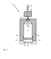
- FIG. 2 shows a detailed schematic view of a mold filling station 5, as shown in FIG FIG. 1 is shown on the carousel 4.
- the mold filling station 5 comprises a mold 6 which is in the form of a hollow mold is trained.
- the mold 6 usually comprises two mold halves 6a and 6b and a bottom 6c, which together can be referred to as moldings.
- the mold filling station comprises a mold / filler block 20 which can be used, for example, for filling and forming the preform 3.
- the mold / filler block 20 comprises, for example, the stretch rod 21 and possibly a closure device 22, which can be positioned over the opening of the preform 3.
- the preform is first introduced into the mold filling station 5 and enclosed by the mold 6 or the mold halves 6a and 6b and the bottom 6c.
- the stretch rod 21 and any supply lines for product and / or compressed air the preform is then formed according to the shape prescribed by the mold 6 to a container. At the same time or after, it can be completely filled.
- the mold halves 6a and 6b as shown in the FIG. 2 are shown, but also the bottom 6c are usually formed in three parts, as for example in FIG. 3a is indicated. It includes the in FIG. 3a shown mold halves a molding or a mold 310, which comes directly into contact with the preform and predetermines the final container shape during molding of the preform. Furthermore, the mold half comprises a mold shell 320, by means of which pressure can be exerted on the mold when the mold halves come into contact, for example by blowing compressed air into the region between the mold shell and the mold, so that the molds of the mold halves are compressed.
- the mold shell 320 with the inner mold 310 is held by a mold carrier 330 of the mold half.
- the mold is opened.
- the opening can be done by translational movement of the mold halves to each other or by the two mold halves are spread around a common center of rotation. It can be provided that this movement is effected by an external drive unit 340, which can drive the individual mold halves. It is not necessary for this purpose, the opening and closing of the mold halves in the production of containers (ie receiving a preform molding and filling within the mold and the release of a container), in this three-part design driving the mold carrier, the shell molds and the To allow molds independently.
- each of the parts of the molds or mold halves is connected via a drive unit with a respective adjacent part of the mold halves, so that these two parts can be moved relative to each other.
- the separate drive units are not shown here. It does not necessarily have to be different drive units.
- the mold halves can also be like in FIG. 3a can be arranged on a common guide 350 and be movable by means of the drive means 340. Alternatively, it can also be provided that a separate guide with one or more stops for defining certain end points of a movement and a corresponding drive unit for moving this part of the mold halves is provided for each of the parts, so the mold 310, the mold shell 320 and the mold carrier 330 ,
- FIG. 3b shows a further embodiment in which the mold halves are formed in two parts.
- the mold half 300 comprises only the mold 310 and the mold carrier 330.
- a drive unit in particular a hydraulic unit 360 are interconnected.
- a drive 340 may be provided for the mold carriers 330 of the mold halves.
- FIG. 3a and 3b can also be provided that the respective mold halves are connected to each other spreadable, so that the two mold halves can be opened. In any case, it is provided that the components of the mold halves are separable from each other, so that the spaces between the individual parts can be cleaned.
- the mold halves are usually moved between a molding position and a receiving position. They are for opening a container in the receiving position (and also for dispensing of the container after it has been formed and filled) opened or opened, wherein they are either rotated about an axis of rotation and thereby spread, or from each other be moved away. In this position, the mold halves are just far enough apart to accommodate a container. In the cleaning position, the distance between the mold halves to each other and in particular the distance of the individual parts of the mold halves may be preferably greater than in the receiving position in order to achieve a good cleaning result.
- FIG. 4a an embodiment of a in the form of filling machine (here only partially represented by the reference numeral 480) integrated cleaning device.
- the cleaning device 490 and 495 can be firmly connected to the mold filling station or the carousel of the mold filling machine or be arranged on the periphery of the mold filling machine.
- An arrangement in a region of the mold filling machine not used for container treatment (molding and filling) is particularly advantageous. Such an area exists, for example, between the transport devices which convey the preforms into the mold-filling machine and the transport devices which transport the finished-shaped and filled containers out of the mold-filling machine.
- the cleaning device 490 or 495 may be formed as a conduit in which a cleaning medium is transported, as in FIG. 4a is shown.
- one or more nozzles 496 may be provided which can apply the cleaning medium to the individual parts of the disassembled mold halves.
- only a single nozzle is movably provided along a guide that can clean the individual parts of the mold halves via a correspondingly flexible lead.
- the nozzle or the nozzles can be pivoted so that the cleaning medium can be applied from different angles to the individual parts of the mold halves. This makes it easier to clean especially hard to reach spaces.
- multistage cleaning processes it can be realized that the individual mold halves are moved apart during each revolution so far that at least cleaning with gas introduced at high pressure is possible.
- either the same nozzles can be used by the liquid cleaning medium is also passed or it can be provided on the cleaning device additional nozzles that can discharge a gaseous medium in the direction of the parts of the mold halves.
- H2O2 hydrogen peroxide
- foaming cleaning media may also be used to ensure thorough cleaning. If the mold halves are at least roughly cleaned during operation, in addition to gaseous cleaning media, it is also possible to use sprays which are, for example, peracetic acid-containing.
- the molds should not be wetted with liquid in operation in order to prevent incorrect molding of the container, it can be provided that the molds are cleaned during operation at least roughly with a gaseous cleaning medium, whereas the remaining parts of the mold halves also during operation can be treated with spray or liquid cleaning media.
- FIG. 4b shows a further embodiment in which the cleaning device or at least a part of the cleaning device 497 is arranged as a ring around the opening in the mold in which the opening of the preform is located.
- This part of the cleaning device can specifically purify the mold 310 in particular. Since it can always lead to undesirable product residues on the mold during the molding and simultaneous or directly subsequent filling of the container, which are disadvantageous for the molding of the following containers, this can be
- Cleaning device for example, using compressed air in each treatment cycle in which the mold is at least partially opened to dispense a container and / or receive a new preform, make a cleaning of the inner surface of the mold.
- compressed air in each treatment cycle in which the mold is at least partially opened to dispense a container and / or receive a new preform, make a cleaning of the inner surface of the mold.
- nozzles may be arranged on a stretching rod which is used for drawing the preform, said nozzles also being able to apply a gaseous or liquid cleaning medium to the inside of the hollow mold.
- the cleaning device was either moved with the mold filling station (ie a separate cleaning device was provided for each mold filling station) or a cleaning device fixedly connected to the mold filling machine, it is also possible to provide either the complete mold filling station or at least the mold comprising the two mold halves, to be moved out of the mold filling machine and into a cleaning device, which arranged next to the mold filling machine to transfer.
- a particularly advantageous embodiment here would be the formation of a cleaning device as a carousel, which is suitable for receiving the molds, so that the individual molds can be cleaned during a cycle around this cleaning device and then returned to the appropriate location in the mold filling station.
- the drive means of the forms of these must be solvable and also the individual guides must be able to release the mold.
- the mold-filling machine and the cleaning device are altogether associated with more molds than mold-filling stations are arranged on the mold-filling machine.
- the molds are transferred from the mold-filling machine to the cleaning device in a first plane and transferred from the cleaning device to the mold-filling machine in a second plane parallel to the first plane but offset along the rotational axis of the carousel.
- a mold can be transferred from the mold filling machine or the carousel to the cleaning device and a mold from the cleaning device to the mold filling machine.
- a cleaning and working cycle can be realized during operation of the mold filling machine and ensure that each mold filling station can always accommodate a container in a clean form.
Landscapes
- Engineering & Computer Science (AREA)
- Mechanical Engineering (AREA)
- Manufacturing & Machinery (AREA)
- Blow-Moulding Or Thermoforming Of Plastics Or The Like (AREA)
- Filling Of Jars Or Cans And Processes For Cleaning And Sealing Jars (AREA)
- Moulds For Moulding Plastics Or The Like (AREA)
Abstract
Description
- Die Erfindung betrifft eine Formfüllmaschine gemäß dem Oberbegriff des Anspruchs 1.
- Bekanntermaßen lassen sich Kunststoffbehälter im Streckblasverfahren aus Vorformlingen herstellen.
- Alternativ zu einem Aufblasen der Behälter mit Pressluft beschreibt die
EP 1529620 B1 ein Verfahren zum hydraulischen Umformen von Vorformlingen zu Kunststoffflaschen. Zu diesem Zweck werden die Vorformlinge zuerst erwärmt, in eine Hohlform verbracht und dort in Längsrichtung gereckt. Es wird ferner Mineralwasser oder dergleichen unter Überdruck eingeleitet, um die endgültige Behälterform herzustellen. Das Mineralwasser verbleibt im Behälter, sodass ein nachfolgender separater Abfüllschritt entbehrlich ist. - Die
US 2011/0031659 A1 beschreibt ferner ein Verfahren, bei dem ein erwärmter Vorformling mittels einer Reckstange gereckt und anschließend mittels eines inkompressiblen Fluids, insbesondere Wasser, hydraulisch zu einem Behälter geweitet wird. Danach wird das Fluid durch Pressluft verdrängt und läuft aus dem Behälter ab. - Eine Formfüllmaschine umfasst definitionsgemäß wenigstens eine Behandlungsstation zum expandierenden Umformen von Kunststoffvorformlingen zu Kunststoffbehältern in einer Hohlform und zum Einfüllen eines im Wesentlichen flüssigen Produkts oder wenigstens einer flüssigen oder festen Komponente des Produkts in die Kunststoffbehälter.
- Flüssigkeiten, auch solche mit darin gelöstem Kohlendioxid oder dergleichen, sind definitionsgemäß hinsichtlich ihrer Funktion beim Ausformen und Füllen der Behälter inkompressible Fluide im Gegensatz zu Gasen, die funktional als kompressible Fluide definiert sind.
- Bei den bekannten Formfüllmaschinen kann es während dem Ausformen und/oder Befüllen mit Produkt zum Platzen des bereits vollständig oder noch nicht vollständig ausgeformten Behälters kommen. Bisherige Maßnahmen zum Entfernen der Überreste des geplatzten Behälters sind langwierig und führen daher zu erheblichen Stillstandszeiten der Formfüllmaschine.
- Aufgabe der vorliegenden Erfindung ist es, bekannte Vorrichtungen und Verfahren zum Ausformen und Füllen von Kunststoffbehältern in vorteilhafter Weise weiterzubilden.
- Diese Aufgabe wird mit einer Formfüllmaschine nach Anspruch 1 gelöst. Vorteilhafte Ausführungsformen der Erfindung sind in den Unteransprüchen definiert.
- Die erfindungsgemäße Formfüllmaschine ist dadurch gekennzeichnet dass die Formhälften relativ zueinander bewegbar sind und eine Reinigungseinrichtung vorgesehen ist, die die geöffneten Formhälften reinigen kann. Somit können auch Verunreinigungen der Formhälften, insbesondere nach dem Platzen eines mit Produkt gefüllten Behälters entfernt werden.
- In einer Ausführungsform der erfindungsgemäßen Formfüllmaschine kann vorgesehen sein, dass die Formhälften dreiteilig ausgebildet sind, wobei jede Formhälfte einen Formträger, eine Formschale und eine Form umfasst und die Teile der Formhälften relativ zueinander bewegbar sind. Somit können die Formhälften nicht nur äußerlich gereinigt werden, sondern auch die Zwischenräume, in denen auch eventuelle Hydraulikeinrichtungen angeordnet sein können, können von Verschmutzungen befreit werden.
- In einer alternativen Ausführungsform kann vorgesehen sein, dass die Formhälften zweiteilig ausgebildet sind und einen Formträger und eine Form umfassen. Dieser im Gegensatz zur vorherigen Ausführungsform reduzierte und kompaktere Aufbau erleichtert die Reinigung der Formhälften.
- In einer vorteilhaften Weiterbildung dieser Ausführungsform ist vorgesehen, dass zwischen den Teilen der Formhälften eine Antriebseinheit angeordnet ist, die die Teile jeder Formhälfte relativ zueinander bewegen kann.
- Es kann vorgesehen sein, dass die Antriebseinheit einer Hydraulikeinheit ist oder diese umfasst. Hydraulische Mittel zur Bewegung der Teile der Formhälften können weniger empfindlich gegenüber Flüssigkeiten ausgeführt werden als beispielsweise elektronische Elemente wie Elektromotoren oder Stellantriebe.
- In einer besonders bevorzugten Weiterbildung diese Ausführungsform ist vorgesehen, dass die Antriebseinheit auch die Formhälften bewegen kann. So können nicht nur die einzelnen Bestandteile der Formhälften relativ zueinander bewegt werden, sondern auch die Formhälften so weit voneinander weg bewegt werden, dass eine effektive Reinigung erreicht werden kann.
- Es kann weiterhin vorgesehen sein dass die Teile der Formhälften jeweils auf einer gemeinsamen Führung angeordnet sind. Somit kann die Anzahl der nötigen Antriebselemente stark reduziert werden und die Bewegung der einzelnen Teile der Formhälften sicher gesteuert werden.
- In einer bevorzugten Ausführungsform der erfindungsgemäßen Formfüllmaschine ist vorgesehen, dass die Formhälften zwischen einer Ausformposition, einer Aufnahmeposition und einer Reinigungsposition verfahrbar sind. Dabei ist die Ausformposition die Position, in der die Formhälften geschlossen sind und ein Behälter innerhalb der Formhälften ausgeformt werden kann. Die Aufnahmeposition entspricht einer geöffneten Position der Formhälften, wobei der Abstand der Formhälften zueinander oder der Öffnungswinkel derart ist, dass ein Vorformling in den Innenbereich der Formhälften aufgenommen werden kann. Die Reinigungsposition ist eine Position, in der die Formhälften und oder die Teile der Formhälften gereinigt werden können. Dazu kann auch vorgesehen sein, dass die Formhälften und/oder die Teile der Formhälften in der Reinigungsposition einen größeren Öffnungswinkel oder Abstand zueinander aufweisen, als in der Aufnahmeposition.
- In einer weiteren Ausführungsform wird entweder ein flüssiges Reinigungsmedium oder ein gasförmiges Reinigungsmedium verwendet. Während die Verwendung eines gasförmigen Reinigungsmediums einen schnellen Wiedereinsatz der Formhälften ermöglicht, da ein Trocknungsschritt entfallen kann, erlaubt die Reinigung mit flüssigen Reinigungsmedien gegebenenfalls eine gründliche Reinigung, so dass sämtliche Verschmutzungen, beispielsweise durch das Platzen von Behältern, entfernt werden können.
- In einer Ausführungsform ist die Reinigungseinrichtung an der Peripherie der Formfüllmaschine angeordnet. Diese Ausführungsform erlaubt das Reinigen einzelner Formhälften, beispielsweise nach einer erkannten Verunreinigung durch umherspritzendes Produkt. Da die Reinigungseinrichtung nicht in der Formfüllmaschine angeordnet ist, kann hier Platz gespart werden.
- In einer alternativen Ausführungsform ist jeder Formfüllstation eine Reinigungseinrichtung zugeordnet. Die Reinigung der Formhälften einer Formfüllstation kann hier unabhängig von den übrigen Formfüllstationen erfolgen. Weiterhin ist durch die in der Formfüllstation mitgeführte Reinigungseinrichtung auch eine Reinigung im Betrieb der Formfüllmaschine möglich, beispielsweise im Zeitintervall zwischen dem Ausgeben eines Behälters aus der Formfüllstation und der Aufnahme eines neuen Vorformlings.
-
- Figur 1:
- schematische Darstellung einer erfindungsgemäßen Formfüllmaschine
- Figur 2:
- schematische Darstellung einer Formfüllstation
- Figur 3a-b:
- schematischer Darstellung von Formhälften dreiteiliger und zweiteiliger Ausführung
- Figur 4a-b:
- schematische Darstellung einer Reinigungseinrichtung
- In
Figur 1 ist eine Fromfüllanlage 1 mit einer erfindungsgemäßen Formfüllmaschine 10 dargestellt. Diese umfasst in der hier dargestellten Ausführungsform ein Karussell 4, das sich in der Drehrichtung 4a drehen kann. An dem Karussell 4 sind ein oder mehrere Formfüllstationen 5 angeordnet, in denen ein Vorformling ausgeformt und befüllt werden kann. Dazu umfassen die Formfüllstationen 5 jeweils eine Hohlform, in der der Vorformling eingespannt werden kann, und in der der Vorformling ausgeformt und gegebenenfalls auch bei geschlossener Hohlform befüllt wird. Zu diesem Zweck ist vorgesehen, dass jede Formfüllstation über ein oder mehrere Füllventile zum Abfüllen von Produkt in den Vorformling und/oder in den Behälter verfügt. - Die Vorformlinge können aus einem Ofenbereich 7 über entsprechende Mittel zum Transport 8, wie beispielsweise Drehsterne oder Förderer, dem Karussell 4 zugeführt werden, wobei der Transport der Vorformlinge beispielsweise im Neck-Handling-Verfahren erfolgen kann. Zwischen dem Ofenbereich 7 und dem Karussell 4 können beispielsweise weitere Behandlungseinrichtungen, wie Inspektionseinrichtungen, Reinigungseinrichtungen oder Ähnliches angeordnet sein.
- Die befüllten und ausgeformten Behälter können aus dem Karussell über eine entsprechende Transporteinrichtung 9, wie beispielsweise einen Drehstern, aus dem Karussell 4 abtransportiert werden. Die ausgeformten und befüllten Behälter 2 können dann beispielsweise weiteren Behandlungseinrichtungen wie einem Verschließer oder Etikettiereinrichtungen oder Druckeinrichtungen zugeführt werden. Diese können ebenfalls als Bestandteil der Formfüllmaschine 10 verstanden werden. Grundsätzlich umfasst die Formfüllmaschine jedoch wenigstens ein Karussell mit entsprechenden Formfüllstationen, in denen die Behälter bzw. Vorformlinge ausgeformt und befüllt werden können.
-
Figur 2 zeigt eine detaillierte schematische Ansicht einer Formfüllstation 5, wie sie inFigur 1 auf dem Karussell 4 dargestellt ist. Die Formfüllstation 5 umfasst eine Form 6, die als Hohlform ausgebildet ist. Die Form 6 umfasst dazu üblicherweise zwei Formhälften 6a und 6b und einen Boden 6c, die zusammen als Formteile bezeichnet werden können. Weiterhin umfasst die Formfüllstation einen Form/Füllblock 20 der beispielsweise zum Befüllen und Ausformen des Vorformlings 3 verwendet werden kann. Dazu umfasst der Form/Füllblock 20 beispielsweise die Reckstange 21 und eventuell eine Verschlusseinrichtung 22, die über der Öffnung des Vorformlings 3 positioniert werden kann. - Um einen Behälter zu formen, wird zunächst der Vorformling in die Formfüllstation 5 eingebracht und von der Form 6 bzw. den Formhälften 6a und 6b und dem Boden 6c umschlossen. Durch die Reckstange 21 und eventuelle Zuleitungen für Produkt und/oder Druckluft wird der Vorformling dann entsprechend der durch die Form 6 vorgegebenen Form zu einem Behälter ausgeformt. Gleichzeitig oder danach kann er vollständig befüllt werden.
- Da in der Formfüllmaschine das Befüllen zeitgleich oder zumindest direkt nach dem Ausformen des Behälters erfolgt, kann es bei Fehlern in der Produktion zum Umherspritzen von Produkt oder zum Platzen von einzelnen Behältern in den Formfüllstationen kommen. Dementsprechend ist eine Reinigung der Formfüllstationen vorteilhaft.
- Die Formhälften 6a und 6b wie sie in der
Figur 2 dargestellt sind, aber auch der Boden 6c sind üblicherweise dreiteilig ausgebildet, wie dies beispielsweise inFigur 3a angedeutet ist. Dabei umfasst die inFigur 3a dargestellt Formhälften ein Formteil bzw. eine Hohlform 310, die direkt mit dem Vorformling in Kontakt tritt und beim Ausformen des Vorformlings die abschließende Behälterform vorgibt. Weiterhin umfasst die Formhälfte eine Formschale 320, mit deren Hilfe Druck auf die Hohlform beim Zusammentreffen der Formhälften ausgeübt werden kann, beispielsweise durch das Einblasen von Druckluft in den Bereich zwischen der Formschale und der Hohlform, sodass die Hohlformen der Formhälften zusammengedrückt werden. - Die Formschale 320 mit der innen liegenden Hohlform 310 wird von einem Formträger 330 der Formhälfte gehalten. Um einen Behälter aufzunehmen, wird die Form geöffnet. Dabei kann das Öffnen durch translatorische Bewegung der Formhälften zueinander erfolgen oder indem die beiden Formhälften um ein gemeinsames Drehzentrum gespreizt werden. Es kann vorgesehen sein, dass diese Bewegung durch eine außen liegende Antriebseinheit 340 bewirkt wird, die die einzelnen Formhälften antreiben kann. Es ist hierfür das Öffnen und Schließen der Formhälften im Rahmen der Produktion von Behältern (also das Aufnehmen eines Vorformlings das Ausformen und Befüllen innerhalb der Form und das Freigeben eines Behälters) nicht notwendig, bei dieser dreiteiligen Ausführung ein Antreiben der Formträger, der Formschalen und der Hohlformen unabhängig voneinander zu ermöglichen.
- Erfindungsgemäß ist jedoch insbesondere mit Hinblick auf die Reinigung vorgesehen, dass jeder der Teile der Formen bzw. Formhälften über eine Antriebseinheit mit einem jeweils benachbarten Teil der Formhälften verbunden ist, sodass auch diese beiden Teile relativ zueinander bewegt werden können. Die separaten Antriebseinheiten sind hier nicht dargestellt. Dabei muss es sich nicht notwendigerweise um unterschiedliche Antriebseinheiten handeln. Die Formhälften können auch wie in
Figur 3a dargestellt auf einer gemeinsamen Führung 350 angeordnet sein und mithilfe der Antriebseinrichtungen 340 bewegbar sein. Alternativ kann auch vorgesehen sein, dass für jeden der Teile, also die Hohlform 310, die Formschale 320 und den Formträger 330 eine separate Führung mit einem oder mehreren Anschlägen zum definieren bestimmter Endpunkte einer Bewegung und eine entsprechende Antriebseinheit zum Bewegen dieses Teils der Formhälften vorgesehen wird. -
Figur 3b zeigt eine weitere Ausführungsform, bei der die Formhälften zweiteilig ausgebildet sind. So umfasst die Formhälfte 300 gemäß diese Ausführungsform nur die Hohlform 310 und den Formträger 330. Um sicherzustellen, dass die Hohlformen 310 zweier Formhälften einer Formfüllstation mit ausreichendem Druck gegeneinander gepresst werden, um das Bilden von unerwünschten Nähten an der Oberfläche des Behälters beim Ausformen zu verhindern, ist es besonders bei der zweiteiligen Ausführung der Formhälften vorteilhaft, wenn die Hohlform 310 und der Formträger 330 über eine Antriebseinheit, insbesondere eine Hydraulikeinheit 360 miteinander verbunden sind. Somit kann der für das Ausformen eines Behälters notwendige Druck der Hohlformen 310 gegeneinander aufgebaut werden. Entweder separat dazu oder als eine Antriebseinheit ausgebildet, kann ein Antrieb 340 für die Formträger 330 der Formhälften vorgesehen sein. - Während die in
Figur 3a und3b dargestellten Formhälften aus Teilen aufgebaut sind, die entlang der dargestellten Führungen translatorisch nach links oder rechts bewegt werden können, kann auch vorgesehen sein, dass die jeweiligen Formhälften miteinander spreizbar verbunden sind, sodass die zwei Formhälften aufgeklappt werden können. In jedem Fall ist vorgesehen, dass die Bestandteile der Formhälften voneinander trennbar sind, sodass die Zwischenräume der einzelnen Teile gereinigt werden können. - Besonders bevorzugt ist es, wenn die einzelnen Teile der Formhälften in einer Reinigungsposition weiter auseinander gefahren sind, als im üblichen Betrieb, sodass die Reinigung auch der Zwischenräume der Teile der Formhälften möglich wird. Im Betrieb werden die Formhälften üblicherweise zwischen einer Ausformposition und einer Aufnahmeposition bewegt. Dabei werden sie zur Aufnahme eines Behälters in der Aufnahmeposition (und auch zum Ausgeben des Behälters nachdem dieser ausgeformt und befüllt wurde) auseinandergefahren bzw. geöffnet, wobei sie entweder um eine Drehachse gedreht und dabei gespreizt werden, oder voneinander weg bewegt werden. In dieser Stellung sind die Formhälften gerade weit genug voneinander entfernt, um einen Behälter aufzunehmen. In der Reinigungsposition kann der Abstand der Formhälften zueinander und insbesondere der Abstand der einzelnen Teile der Formhälften vorzugsweise größer sein, als in der Aufnahmeposition, um ein gutes Reinigungsergebnis zu erzielen.
- Dazu zeigt
Figur 4a eine Ausführungsform einer in die Formfüllmaschine (hier nur ausschnittsweise mit dem Bezugszeichen 480 dargestellt) integrierten Reinigungseinrichtung. Die Reinigungseinrichtung 490 und 495 kann dabei fest mit der Formfüllstation oder dem Karussell der Formfüllmaschine verbunden sein oder an der Peripherie der Formfüllmaschine angeordnet sein. Besonders vorteilhaft ist eine Anordnung in einem für die Behälterbehandlung (Ausformen und Befüllen) nicht verwendeten Bereich der Formfüllmaschine. Einen solchen Bereich gibt es beispielsweise zwischen den Transporteinrichtungen, die die Vorformlinge in die Formfüllmaschine befördern, und den Transporteinrichtungen, die die fertig geformten und befüllten Behälter aus der Formfüllmaschine abtransportieren. - Die Reinigungseinrichtung 490 bzw. 495 kann als Leitung ausgebildet sein, in der ein Reinigungsmedium transportiert wird, wie dies in
Figur 4a dargestellt ist. Zum Ausbringen des Reinigungsmediums können eine oder mehrere Düsen 496 vorgesehen sein, die das Reinigungsmedium auf die einzelnen Teile der auseinander gefahrenen Formhälften aufbringen können. Um Platz zu sparen kann auch vorgesehen sein, dass nur eine einzelne Düse beweglich entlang einer Führung vorgesehen ist, die über eine entsprechend flexibler Zuleitung die einzelnen Teile der Formhälften reinigen kann. Besonders vorteilhaft ist weiterhin, wenn die Düse oder die Düsen verschwenkt werden können, sodass das Reinigungsmedium aus unterschiedlichen Winkeln auf die einzelnen Teile der Formhälften aufgebracht werden kann. Damit kann das Reinigen insbesondere schwer zugänglicher Zwischenräume erleichtert werden. - Sind die Formhälften, wie in
Figur 4a dargestellt, auseinander gezogen bzw. auseinander gefahren, so kann auch vorgesehen sein, dass senkrecht zur Zeichenebene in freie Bereiche zusätzliche Düsen eingeführt werden (beispielsweise an entsprechenden Lanzen oder Führungen) um auch den innen liegenden Bereich der einzelnen Bestandteile der Formhälften reinigen zu können. Diese Ausführungsform ist insbesondere bei mit den Formfüllstationen mitgeführten Reinigungseinrichtungen vorteilhaft, da hier keine oder nur eine geringe Bewegung der Formhälften oder der Bestandteile der Formhälften relativ zur Reinigungseinrichtung während eines Reinigungsschritts erfolgt. - Demgegenüber erfolgt bei einer fest an der Formfüllmaschine (nicht mit dem Karussell, wie es in
Fig. 1 dargestellt ist, mitdrehend) montierten Reinigungseinrichtung eine Bewegung der einzelnen Formhälften relativ zur Reinigungseinrichtung. In diesem Fall kann vorgesehen sein, dass die einzelnen Düsen 496 Reinigungsmedium aus unterschiedlichen Winkeln auf die Bestandteile der Formfüllstation leiten, um eine vollständige Reinigung gewährleisten zu können. - Bei der Reinigung kann grundsätzlich Medium mit hohem Druck zur Reinigung eingesetzt werden, um das Entfernen auch fester Rückstände, die beispielsweise beim Platzen eines Behälters in der Hohlform verbleiben können, sicherzustellen.
- Abhängig vom Durchsatz der Formfüllmaschine kann auch vorgesehen sein, dass mehrstufige Reinigungsprozesse zum Einsatz kommen. So kann es abhängig von der Rotationsgeschwindigkeit realisierbar sein, dass die einzelnen Formhälften bei jedem Umlauf soweit auseinander gefahren werden, dass zumindest eine Reinigung mit unter Hochdruck eingelassenem Gas möglich ist. Dazu können entweder dieselben Düsen verwendet werden durch die auch flüssiges Reinigungsmedium geleitet wird oder es können an der Reinigungseinrichtung zusätzliche Düsen vorgesehen sein, die ein gasförmiges Medium in Richtung der Teile der Formhälften ausleiten können. Dabei kann insbesondere H2O2 (Wasserstoffperoxid) verwendet werden, da dies eine desinfizierende Wirkung besitzt.
- Insbesondere wenn die Reinigung der Teile der Formhälften nur im Falle des Platzens eines Behälters oder anderer unvorhergesehener Verunreinigungen erfolgt, die gleichzeitig mit einem Stillstand oder Wartungsarbeiten der Formfüllmaschine einhergehen, können auch Reinigungsmedien mit Schaumentwicklung zum Einsatz kommen, um eine gründliche Reinigung zu gewährleisten. Werden die Formhälften auch während des Betriebs zumindest grob gereinigt, können neben gasförmigen Reinigungsmedien auch Sprühnebel verwendet werden, die beispielsweise peressigsäurehaltig sind.
- Da die Hohlformen jedoch im Betrieb nicht mit Flüssigkeit benetzt werden sollten, um ein fehlerhaftes Ausformen der Behälter zu verhindern, kann vorgesehen sein, dass die Hohlformen während des Betriebs zumindest grob mit einem gasförmigen Reinigungsmedium gereinigt werden wohingegen die übrigen Teile der Formhälften auch während des Betriebs mit Sprühnebel oder flüssigen Reinigungsmedien behandelt werden können.
-
Figur 4b zeigt eine weitere Ausführungsform bei der die Reinigungseinrichtung oder zumindest ein Teil der Reinigungseinrichtung 497 als Ring um die Öffnung in der Form, in der sich die Öffnung des Vorformlings befindet, angeordnet ist. Dieser Teil der Reinigungseinrichtung kann insbesondere die Hohlform 310 gezielt reinigen. Da es beim Ausformen und gleichzeitigem oder direkt nachfolgendem Befüllen der Behälter stets zu unerwünschten Produktresten an der Hohlform kommen kann, die nachteilig für das Ausformen folgender Behälter sind, kann diese - Reinigungseinrichtung beispielsweise unter Verwendung von Druckluft bei jedem Behandlungszyklus, bei dem die Hohlform zumindest teilweise geöffnet wird um einen Behälter auszugeben und/oder einen neuen Vorformling aufzunehmen, eine Reinigung der Innenfläche der Hohlform vornehmen. Somit können unerwünschte Nebeneffekte durch Verunreinigungen vermieden werden.
- Alternativ oder zusätzlich dazu kann auch vorgesehen sein, dass an einer Reckstange, die für das Verstrecken des Vorformlings verwendet wird, Düsen angeordnet sind, die ebenfalls ein gasförmiges oder flüssiges Reinigungsmedium auf die Innenseite der Hohlform auftragen können.
- Während in den obigen Ausführungsformen die Reinigungseinrichtung entweder mit der Formfüllstation mit bewegt wurde (also beispielsweise für jede Formfüllstation eine separate Reinigungseinrichtung vorgesehen war) oder eine mit der Formfüllmaschine fest verbundene Reinigungseinrichtung vorgesehen war, kann auch vorgesehen sein, entweder die komplette Formfüllstation oder zumindest die Form, umfassend die beiden Formhälften, aus der Formfüllmaschine herauszufahren und in eine Reinigungseinrichtung, die neben der Formfüllmaschine angeordnet, zu überführen.
- Eine besonders vorteilhaft Ausführungsform wäre hier das Ausbilden einer Reinigungseinrichtung als Karussell, das zur Aufnahme der Formen geeignet ist, sodass die einzelnen Formen während eines Umlauf um diese Reinigungseinrichtung gereinigt werden und anschließend an die passende Stelle in der Formfüllstation zurückgegeben werden können. Zu diesem Zweck müssen die Antriebseinrichtungen der Formen von diesen lösbar sein und ebenso müssen die einzelnen Führungen die Form freigeben können. Vorteilhaft ist hier auch, wenn der Formfüllmaschine und der Reinigungseinrichtung insgesamt mehr Formen zugeordnet sind, als Formfüllstationen an der Formfüllmaschine angeordnet sind. So können die Formen der Formfüllstationen nach dem Ausformen und Befüllen eines Behälters der Reinigungseinrichtung zugeführt werden und eine gereinigte Form aus der Reinigungseinrichtung dem Karussell zugeführt werden. Damit kann eine kontinuierliche Reinigung der Formhälften realisiert werden.
- Besonders vorteilhaft ist es hier, wenn die Formen in einer ersten Ebene aus der Formfüllmaschine an die Reinigungseinrichtung übergeben werden und in einer zweiten, zur ersten Ebene parallelen aber entlang der Rotationsachse des Karussells versetzten Ebene von der Reinigungseinrichtung an die Formfüllmaschine übergeben werden. So kann zeitgleich eine Form von der Formfüllmaschine bzw. dem Karussell an die Reinigungseinrichtung und eine Form von der Reinigungseinrichtung an die Formfüllmaschine übergeben werden. So kann ein Reinigungs- und Arbeitskreislauf während des Betriebs der Formfüllmaschine realisiert werden und sichergestellt werden, dass jede Formfüllstation stets einen Behälter in eine saubere Form aufnehmen kann.
Claims (11)
- Formfüllmaschine (10) zum Formen von Vorformlingen zu Behältern und Füllen der Behälter, mit einer oder mehrerer Formfüllstationen (5), in denen der Vorformling in einer Form (6) ausgeformt und der Behälter befüllt werden kann und die jeweils zwei Formhälften (6a, 6b) umfassen, dadurch gekennzeichnet, dass die Formhälften (6a, 6b)zum Öffnen relativ zueinander bewegbar sind und eine Reinigungseinrichtung (490, 495) vorgesehen ist, die die geöffneten Formhälften (6a, 6b) reinigen kann.
- Formfüllmaschine nach Anspruch 1, dadurch gekennzeichnet, dass die Formhälften dreiteilig ausgebildet sind und einen Formträger (330), eine Formschale (320) und eine Hohlform (310) umfassen, wobei die Teile der Formhälften (6a, 6b) relativ zueinander bewegbar sind.
- Formfüllmaschine nach Anspruch 1, dadurch gekennzeichnet, dass die Formhälften (6a, 6b) zweiteilig ausgebildet sind und einen Formträger und eine Hohlform (310) umfassen.
- Formfüllmaschine nach Anspruch 2 oder 3, dadurch gekennzeichnet, dass zwischen den Teilen der Formhälften (6a, 6b) eine Antriebseinheit angeordnet ist, die die Teile jeder Formhälfte (6a, 6b) relativ zueinander bewegen kann.
- Formfüllmaschine nach Anspruch 4 oder 5, dadurch gekennzeichnet, dass die Antriebseinheit eine Hydraulikeinheit ist oder diese umfasst.
- Formfüllmaschine nach Anspruch 5, dadurch gekennzeichnet, dass die Antriebseinheit die Formhälften (6a, 6b) bewegen kann.
- Formfüllmaschine nach Anspruch 2 oder 3, dadurch gekennzeichnet, dass die Teile der Formhälften (6a, 6b) jeweils auf einer gemeinsamen Führung angeordnet sind.
- Formfüllmaschine nach einem der Ansprüche 1 bis 7, dadurch gekennzeichnet, dass die Formhälften (6a, 6b) zwischen einer Ausformposition, einer Aufnahmeposition und einer Reinigungsposition verfahrbar sind.
- Formfüllmaschine nach einem der Ansprüche 1 bis 8, dadurch gekennzeichnet, dass ein flüssiges Reinigungsmedium oder ein gasförmiges Reinigungsmedium verwendet wird.
- Formfüllmaschine nach einem der Ansprüche 1 bis 9, dadurch gekennzeichnet, dass die Reinigungseinrichtung an einer Peripherie der Formfüllmaschine angeordnet ist.
- Formfüllmaschine nach einem der Ansprüche 1 bis 9, dadurch gekennzeichnet, dass jeder Formfüllstation (5) jeweils eine Reinigungseinrichtung zugeordnet ist.
Priority Applications (1)
| Application Number | Priority Date | Filing Date | Title |
|---|---|---|---|
| EP14181663.7A EP2987613B1 (de) | 2014-08-20 | 2014-08-20 | Formfüllmaschine |
Applications Claiming Priority (1)
| Application Number | Priority Date | Filing Date | Title |
|---|---|---|---|
| EP14181663.7A EP2987613B1 (de) | 2014-08-20 | 2014-08-20 | Formfüllmaschine |
Publications (2)
| Publication Number | Publication Date |
|---|---|
| EP2987613A1 true EP2987613A1 (de) | 2016-02-24 |
| EP2987613B1 EP2987613B1 (de) | 2018-04-04 |
Family
ID=51389992
Family Applications (1)
| Application Number | Title | Priority Date | Filing Date |
|---|---|---|---|
| EP14181663.7A Active EP2987613B1 (de) | 2014-08-20 | 2014-08-20 | Formfüllmaschine |
Country Status (1)
| Country | Link |
|---|---|
| EP (1) | EP2987613B1 (de) |
Cited By (1)
| Publication number | Priority date | Publication date | Assignee | Title |
|---|---|---|---|---|
| US20140174034A1 (en) * | 2011-05-19 | 2014-06-26 | Alfred Drenguis | Method and device for producing filled containers made from preforms |
Citations (4)
| Publication number | Priority date | Publication date | Assignee | Title |
|---|---|---|---|---|
| EP1529620B1 (de) | 2003-11-06 | 2009-02-25 | Nestlé Waters Management & Technology | Herstellungsverfahren von Behältern aus Polyesterharz |
| US20110031659A1 (en) | 2005-03-15 | 2011-02-10 | Graeme Warner | Stretch Blow Moulding Method and Apparatus |
| WO2012156013A1 (de) * | 2011-05-19 | 2012-11-22 | Khs Gmbh | Verfahren und vorrichtung zum reinigen und/oder desinfizieren einer vorrichtung zur herstellung von mit einem flüssigen füllgut gefüllten behältern |
| WO2014095386A1 (en) * | 2012-12-19 | 2014-06-26 | Nestec S.A. | Apparatus and method for fabricating containers |
-
2014
- 2014-08-20 EP EP14181663.7A patent/EP2987613B1/de active Active
Patent Citations (4)
| Publication number | Priority date | Publication date | Assignee | Title |
|---|---|---|---|---|
| EP1529620B1 (de) | 2003-11-06 | 2009-02-25 | Nestlé Waters Management & Technology | Herstellungsverfahren von Behältern aus Polyesterharz |
| US20110031659A1 (en) | 2005-03-15 | 2011-02-10 | Graeme Warner | Stretch Blow Moulding Method and Apparatus |
| WO2012156013A1 (de) * | 2011-05-19 | 2012-11-22 | Khs Gmbh | Verfahren und vorrichtung zum reinigen und/oder desinfizieren einer vorrichtung zur herstellung von mit einem flüssigen füllgut gefüllten behältern |
| WO2014095386A1 (en) * | 2012-12-19 | 2014-06-26 | Nestec S.A. | Apparatus and method for fabricating containers |
Cited By (2)
| Publication number | Priority date | Publication date | Assignee | Title |
|---|---|---|---|---|
| US20140174034A1 (en) * | 2011-05-19 | 2014-06-26 | Alfred Drenguis | Method and device for producing filled containers made from preforms |
| US10457426B2 (en) * | 2011-05-19 | 2019-10-29 | Khs Gmbh | Method and device for producing filled containers made from preforms |
Also Published As
| Publication number | Publication date |
|---|---|
| EP2987613B1 (de) | 2018-04-04 |
Similar Documents
| Publication | Publication Date | Title |
|---|---|---|
| DE102011102090B4 (de) | Verfahren zum Reinigen und/oder Desinfizieren einer Vorrichtung zur Herstellung von mit einem flüssigen Füllgut gefüllten Behältern sowie Vorrichtung | |
| EP2307184B1 (de) | Anlage zum herstellen von behältnissen mit einer vorrichtung zum behandeln einer aussenwandung der behältnisse mit einer beweglichen zuführeinrichtung und dazugehöriges verfahren | |
| DE102011102056B4 (de) | Verfahren sowie Vorrichtung zum Herstellen von gefüllten Behältern aus Vorformlingen | |
| EP2878425B1 (de) | Blasformmaschine mit Wechselroboter und Verfahren zu deren Betrieb | |
| EP2734463B1 (de) | Modul zum ausrichten von behältnissen und verfahren zum ausrichten von behältnissen | |
| DE102014103671B3 (de) | Behälterbehandlungsmaschine sowie Verfahren zum Zu- und/oder Abführen von Behältern zu einer Behälterbehandlungsmaschine | |
| EP2537662B1 (de) | Vorrichtung und Verfahren zum Umformen von Kunststoffvorformlingen zu Kunststoffbehältnissen mit abgedichteter Reckstangenbewegung | |
| EP2332867A1 (de) | Vorrichtung und Verfahren zum Transportieren von Behältnissen mit Bodenführung | |
| DE69607636T2 (de) | Vorrichtung zur herstellung von behältern aus kunststoffmaterial | |
| EP3109198B1 (de) | Behältnisbehandlungsanlage mit sterilraum und flüssigkeitsabführung aus diesem sterilraum | |
| EP2522485B1 (de) | Aseptische Blasformmaschine sowie -verfahren und Blasform mit steriler Luftabführung | |
| DE10261706B4 (de) | Füllmaschine und Verfahren zum Abfüllen von Lebensmitteln | |
| EP2987618B1 (de) | Formfüllmaschine und Verfahren zum Formen und Füllen von Behältern | |
| EP2987613B1 (de) | Formfüllmaschine | |
| DE19721529B4 (de) | Anordnung und Verfahren zur Durchführung der Dichtigkeitsprüfung für Flaschen aus Kunststoff | |
| DE102012101239A1 (de) | Blasmaschine, transporteinrichtung und verfahren zum blasformen eines behälters mit der blasmaschine | |
| WO2017144157A2 (de) | Bearbeitungsvorrichtung, anlage und bearbeitungsverfahren für behälter unterschiedlicher typen | |
| EP3310551B1 (de) | Formfüllmaschine | |
| EP2987609A1 (de) | Formfüllmaschine mit Reinigung und Verfahren | |
| EP3645237B1 (de) | Verfahren, vorrichtung, arbeitsrad und umformstation für die herstellung von gefüllten behältern aus temperaturkonditionierten vorformlingen | |
| EP3088160B1 (de) | Verfahren und vorrichtung zum umformen von kunststoffvorformlingen mit behältniskühlung | |
| EP2987732B1 (de) | Formfüllmaschine | |
| DE102009055693B4 (de) | Extrusions- und Blasverfahren | |
| DE102019116598A1 (de) | Verfahren und Vorrichtung zum Herstellen von gefüllten Behältern aus Vorformlingen | |
| WO2019115325A1 (de) | Vorrichtung und verfahren zum umformen von kunststoffvorformlingen zu kunststoffbehältnissen mit tangentialer ausleitung der kunststoffbehältnisse aus der blasformmaschine |
Legal Events
| Date | Code | Title | Description |
|---|---|---|---|
| PUAI | Public reference made under article 153(3) epc to a published international application that has entered the european phase |
Free format text: ORIGINAL CODE: 0009012 |
|
| AK | Designated contracting states |
Kind code of ref document: A1 Designated state(s): AL AT BE BG CH CY CZ DE DK EE ES FI FR GB GR HR HU IE IS IT LI LT LU LV MC MK MT NL NO PL PT RO RS SE SI SK SM TR |
|
| AX | Request for extension of the european patent |
Extension state: BA ME |
|
| 17P | Request for examination filed |
Effective date: 20160406 |
|
| RBV | Designated contracting states (corrected) |
Designated state(s): AL AT BE BG CH CY CZ DE DK EE ES FI FR GB GR HR HU IE IS IT LI LT LU LV MC MK MT NL NO PL PT RO RS SE SI SK SM TR |
|
| GRAP | Despatch of communication of intention to grant a patent |
Free format text: ORIGINAL CODE: EPIDOSNIGR1 |
|
| INTG | Intention to grant announced |
Effective date: 20171108 |
|
| GRAS | Grant fee paid |
Free format text: ORIGINAL CODE: EPIDOSNIGR3 |
|
| GRAA | (expected) grant |
Free format text: ORIGINAL CODE: 0009210 |
|
| AK | Designated contracting states |
Kind code of ref document: B1 Designated state(s): AL AT BE BG CH CY CZ DE DK EE ES FI FR GB GR HR HU IE IS IT LI LT LU LV MC MK MT NL NO PL PT RO RS SE SI SK SM TR |
|
| REG | Reference to a national code |
Ref country code: GB Ref legal event code: FG4D Free format text: NOT ENGLISH |
|
| REG | Reference to a national code |
Ref country code: CH Ref legal event code: EP Ref country code: CH Ref legal event code: NV Representative=s name: BOVARD AG PATENT- UND MARKENANWAELTE, CH |
|
| REG | Reference to a national code |
Ref country code: AT Ref legal event code: REF Ref document number: 985133 Country of ref document: AT Kind code of ref document: T Effective date: 20180415 |
|
| REG | Reference to a national code |
Ref country code: DE Ref legal event code: R096 Ref document number: 502014007821 Country of ref document: DE |
|
| REG | Reference to a national code |
Ref country code: IE Ref legal event code: FG4D Free format text: LANGUAGE OF EP DOCUMENT: GERMAN |
|
| REG | Reference to a national code |
Ref country code: FR Ref legal event code: PLFP Year of fee payment: 5 |
|
| REG | Reference to a national code |
Ref country code: NL Ref legal event code: MP Effective date: 20180404 |
|
| REG | Reference to a national code |
Ref country code: LT Ref legal event code: MG4D |
|
| PG25 | Lapsed in a contracting state [announced via postgrant information from national office to epo] |
Ref country code: NL Free format text: LAPSE BECAUSE OF FAILURE TO SUBMIT A TRANSLATION OF THE DESCRIPTION OR TO PAY THE FEE WITHIN THE PRESCRIBED TIME-LIMIT Effective date: 20180404 |
|
| PG25 | Lapsed in a contracting state [announced via postgrant information from national office to epo] |
Ref country code: BG Free format text: LAPSE BECAUSE OF FAILURE TO SUBMIT A TRANSLATION OF THE DESCRIPTION OR TO PAY THE FEE WITHIN THE PRESCRIBED TIME-LIMIT Effective date: 20180704 Ref country code: FI Free format text: LAPSE BECAUSE OF FAILURE TO SUBMIT A TRANSLATION OF THE DESCRIPTION OR TO PAY THE FEE WITHIN THE PRESCRIBED TIME-LIMIT Effective date: 20180404 Ref country code: NO Free format text: LAPSE BECAUSE OF FAILURE TO SUBMIT A TRANSLATION OF THE DESCRIPTION OR TO PAY THE FEE WITHIN THE PRESCRIBED TIME-LIMIT Effective date: 20180704 Ref country code: PL Free format text: LAPSE BECAUSE OF FAILURE TO SUBMIT A TRANSLATION OF THE DESCRIPTION OR TO PAY THE FEE WITHIN THE PRESCRIBED TIME-LIMIT Effective date: 20180404 Ref country code: AL Free format text: LAPSE BECAUSE OF FAILURE TO SUBMIT A TRANSLATION OF THE DESCRIPTION OR TO PAY THE FEE WITHIN THE PRESCRIBED TIME-LIMIT Effective date: 20180404 Ref country code: SE Free format text: LAPSE BECAUSE OF FAILURE TO SUBMIT A TRANSLATION OF THE DESCRIPTION OR TO PAY THE FEE WITHIN THE PRESCRIBED TIME-LIMIT Effective date: 20180404 Ref country code: ES Free format text: LAPSE BECAUSE OF FAILURE TO SUBMIT A TRANSLATION OF THE DESCRIPTION OR TO PAY THE FEE WITHIN THE PRESCRIBED TIME-LIMIT Effective date: 20180404 Ref country code: LT Free format text: LAPSE BECAUSE OF FAILURE TO SUBMIT A TRANSLATION OF THE DESCRIPTION OR TO PAY THE FEE WITHIN THE PRESCRIBED TIME-LIMIT Effective date: 20180404 |
|
| PG25 | Lapsed in a contracting state [announced via postgrant information from national office to epo] |
Ref country code: LV Free format text: LAPSE BECAUSE OF FAILURE TO SUBMIT A TRANSLATION OF THE DESCRIPTION OR TO PAY THE FEE WITHIN THE PRESCRIBED TIME-LIMIT Effective date: 20180404 Ref country code: HR Free format text: LAPSE BECAUSE OF FAILURE TO SUBMIT A TRANSLATION OF THE DESCRIPTION OR TO PAY THE FEE WITHIN THE PRESCRIBED TIME-LIMIT Effective date: 20180404 Ref country code: GR Free format text: LAPSE BECAUSE OF FAILURE TO SUBMIT A TRANSLATION OF THE DESCRIPTION OR TO PAY THE FEE WITHIN THE PRESCRIBED TIME-LIMIT Effective date: 20180705 Ref country code: RS Free format text: LAPSE BECAUSE OF FAILURE TO SUBMIT A TRANSLATION OF THE DESCRIPTION OR TO PAY THE FEE WITHIN THE PRESCRIBED TIME-LIMIT Effective date: 20180404 |
|
| PG25 | Lapsed in a contracting state [announced via postgrant information from national office to epo] |
Ref country code: PT Free format text: LAPSE BECAUSE OF FAILURE TO SUBMIT A TRANSLATION OF THE DESCRIPTION OR TO PAY THE FEE WITHIN THE PRESCRIBED TIME-LIMIT Effective date: 20180806 |
|
| REG | Reference to a national code |
Ref country code: DE Ref legal event code: R097 Ref document number: 502014007821 Country of ref document: DE |
|
| PG25 | Lapsed in a contracting state [announced via postgrant information from national office to epo] |
Ref country code: EE Free format text: LAPSE BECAUSE OF FAILURE TO SUBMIT A TRANSLATION OF THE DESCRIPTION OR TO PAY THE FEE WITHIN THE PRESCRIBED TIME-LIMIT Effective date: 20180404 Ref country code: DK Free format text: LAPSE BECAUSE OF FAILURE TO SUBMIT A TRANSLATION OF THE DESCRIPTION OR TO PAY THE FEE WITHIN THE PRESCRIBED TIME-LIMIT Effective date: 20180404 Ref country code: RO Free format text: LAPSE BECAUSE OF FAILURE TO SUBMIT A TRANSLATION OF THE DESCRIPTION OR TO PAY THE FEE WITHIN THE PRESCRIBED TIME-LIMIT Effective date: 20180404 Ref country code: CZ Free format text: LAPSE BECAUSE OF FAILURE TO SUBMIT A TRANSLATION OF THE DESCRIPTION OR TO PAY THE FEE WITHIN THE PRESCRIBED TIME-LIMIT Effective date: 20180404 Ref country code: SK Free format text: LAPSE BECAUSE OF FAILURE TO SUBMIT A TRANSLATION OF THE DESCRIPTION OR TO PAY THE FEE WITHIN THE PRESCRIBED TIME-LIMIT Effective date: 20180404 |
|
| PLBE | No opposition filed within time limit |
Free format text: ORIGINAL CODE: 0009261 |
|
| STAA | Information on the status of an ep patent application or granted ep patent |
Free format text: STATUS: NO OPPOSITION FILED WITHIN TIME LIMIT |
|
| PG25 | Lapsed in a contracting state [announced via postgrant information from national office to epo] |
Ref country code: SM Free format text: LAPSE BECAUSE OF FAILURE TO SUBMIT A TRANSLATION OF THE DESCRIPTION OR TO PAY THE FEE WITHIN THE PRESCRIBED TIME-LIMIT Effective date: 20180404 |
|
| 26N | No opposition filed |
Effective date: 20190107 |
|
| PG25 | Lapsed in a contracting state [announced via postgrant information from national office to epo] |
Ref country code: MC Free format text: LAPSE BECAUSE OF FAILURE TO SUBMIT A TRANSLATION OF THE DESCRIPTION OR TO PAY THE FEE WITHIN THE PRESCRIBED TIME-LIMIT Effective date: 20180404 |
|
| GBPC | Gb: european patent ceased through non-payment of renewal fee |
Effective date: 20180820 |
|
| PG25 | Lapsed in a contracting state [announced via postgrant information from national office to epo] |
Ref country code: LU Free format text: LAPSE BECAUSE OF NON-PAYMENT OF DUE FEES Effective date: 20180820 |
|
| REG | Reference to a national code |
Ref country code: BE Ref legal event code: MM Effective date: 20180831 |
|
| REG | Reference to a national code |
Ref country code: IE Ref legal event code: MM4A |
|
| PG25 | Lapsed in a contracting state [announced via postgrant information from national office to epo] |
Ref country code: SI Free format text: LAPSE BECAUSE OF FAILURE TO SUBMIT A TRANSLATION OF THE DESCRIPTION OR TO PAY THE FEE WITHIN THE PRESCRIBED TIME-LIMIT Effective date: 20180404 |
|
| PG25 | Lapsed in a contracting state [announced via postgrant information from national office to epo] |
Ref country code: IE Free format text: LAPSE BECAUSE OF NON-PAYMENT OF DUE FEES Effective date: 20180820 |
|
| PG25 | Lapsed in a contracting state [announced via postgrant information from national office to epo] |
Ref country code: BE Free format text: LAPSE BECAUSE OF NON-PAYMENT OF DUE FEES Effective date: 20180831 |
|
| PG25 | Lapsed in a contracting state [announced via postgrant information from national office to epo] |
Ref country code: GB Free format text: LAPSE BECAUSE OF NON-PAYMENT OF DUE FEES Effective date: 20180820 |
|
| PG25 | Lapsed in a contracting state [announced via postgrant information from national office to epo] |
Ref country code: MT Free format text: LAPSE BECAUSE OF FAILURE TO SUBMIT A TRANSLATION OF THE DESCRIPTION OR TO PAY THE FEE WITHIN THE PRESCRIBED TIME-LIMIT Effective date: 20180404 |
|
| PG25 | Lapsed in a contracting state [announced via postgrant information from national office to epo] |
Ref country code: TR Free format text: LAPSE BECAUSE OF FAILURE TO SUBMIT A TRANSLATION OF THE DESCRIPTION OR TO PAY THE FEE WITHIN THE PRESCRIBED TIME-LIMIT Effective date: 20180404 |
|
| PG25 | Lapsed in a contracting state [announced via postgrant information from national office to epo] |
Ref country code: HU Free format text: LAPSE BECAUSE OF FAILURE TO SUBMIT A TRANSLATION OF THE DESCRIPTION OR TO PAY THE FEE WITHIN THE PRESCRIBED TIME-LIMIT; INVALID AB INITIO Effective date: 20140820 Ref country code: MK Free format text: LAPSE BECAUSE OF NON-PAYMENT OF DUE FEES Effective date: 20180404 Ref country code: CY Free format text: LAPSE BECAUSE OF FAILURE TO SUBMIT A TRANSLATION OF THE DESCRIPTION OR TO PAY THE FEE WITHIN THE PRESCRIBED TIME-LIMIT Effective date: 20180404 |
|
| PG25 | Lapsed in a contracting state [announced via postgrant information from national office to epo] |
Ref country code: IS Free format text: LAPSE BECAUSE OF FAILURE TO SUBMIT A TRANSLATION OF THE DESCRIPTION OR TO PAY THE FEE WITHIN THE PRESCRIBED TIME-LIMIT Effective date: 20180804 |
|
| REG | Reference to a national code |
Ref country code: AT Ref legal event code: MM01 Ref document number: 985133 Country of ref document: AT Kind code of ref document: T Effective date: 20190820 |
|
| PG25 | Lapsed in a contracting state [announced via postgrant information from national office to epo] |
Ref country code: AT Free format text: LAPSE BECAUSE OF NON-PAYMENT OF DUE FEES Effective date: 20190820 |
|
| P01 | Opt-out of the competence of the unified patent court (upc) registered |
Effective date: 20230523 |
|
| PGFP | Annual fee paid to national office [announced via postgrant information from national office to epo] |
Ref country code: IT Payment date: 20230711 Year of fee payment: 10 Ref country code: CH Payment date: 20230902 Year of fee payment: 10 |
|
| PGFP | Annual fee paid to national office [announced via postgrant information from national office to epo] |
Ref country code: FR Payment date: 20230703 Year of fee payment: 10 Ref country code: DE Payment date: 20230703 Year of fee payment: 10 |
|
| REG | Reference to a national code |
Ref country code: DE Ref legal event code: R119 Ref document number: 502014007821 Country of ref document: DE |
|
| REG | Reference to a national code |
Ref country code: CH Ref legal event code: PL |
|
| PG25 | Lapsed in a contracting state [announced via postgrant information from national office to epo] |
Ref country code: CH Free format text: LAPSE BECAUSE OF NON-PAYMENT OF DUE FEES Effective date: 20240831 |
|
| PG25 | Lapsed in a contracting state [announced via postgrant information from national office to epo] |
Ref country code: DE Free format text: LAPSE BECAUSE OF NON-PAYMENT OF DUE FEES Effective date: 20250301 |
|
| PG25 | Lapsed in a contracting state [announced via postgrant information from national office to epo] |
Ref country code: IT Free format text: LAPSE BECAUSE OF NON-PAYMENT OF DUE FEES Effective date: 20240820 |
|
| PG25 | Lapsed in a contracting state [announced via postgrant information from national office to epo] |
Ref country code: FR Free format text: LAPSE BECAUSE OF NON-PAYMENT OF DUE FEES Effective date: 20240831 |