EP2987378B1 - Method and apparatus for configuring uplink and downlink serving cells in wireless communications - Google Patents
Method and apparatus for configuring uplink and downlink serving cells in wireless communications Download PDFInfo
- Publication number
- EP2987378B1 EP2987378B1 EP14726053.3A EP14726053A EP2987378B1 EP 2987378 B1 EP2987378 B1 EP 2987378B1 EP 14726053 A EP14726053 A EP 14726053A EP 2987378 B1 EP2987378 B1 EP 2987378B1
- Authority
- EP
- European Patent Office
- Prior art keywords
- cell
- uplink
- downlink
- receiving
- serving
- Prior art date
- Legal status (The legal status is an assumption and is not a legal conclusion. Google has not performed a legal analysis and makes no representation as to the accuracy of the status listed.)
- Active
Links
Images


Classifications
-
- H—ELECTRICITY
- H04—ELECTRIC COMMUNICATION TECHNIQUE
- H04W—WIRELESS COMMUNICATION NETWORKS
- H04W52/00—Power management, e.g. TPC [Transmission Power Control], power saving or power classes
- H04W52/04—TPC
- H04W52/18—TPC being performed according to specific parameters
- H04W52/26—TPC being performed according to specific parameters using transmission rate or quality of service QoS [Quality of Service]
- H04W52/267—TPC being performed according to specific parameters using transmission rate or quality of service QoS [Quality of Service] taking into account the information rate
-
- H—ELECTRICITY
- H04—ELECTRIC COMMUNICATION TECHNIQUE
- H04W—WIRELESS COMMUNICATION NETWORKS
- H04W72/00—Local resource management
- H04W72/04—Wireless resource allocation
-
- H—ELECTRICITY
- H04—ELECTRIC COMMUNICATION TECHNIQUE
- H04B—TRANSMISSION
- H04B7/00—Radio transmission systems, i.e. using radiation field
- H04B7/02—Diversity systems; Multi-antenna system, i.e. transmission or reception using multiple antennas
- H04B7/022—Site diversity; Macro-diversity
-
- H—ELECTRICITY
- H04—ELECTRIC COMMUNICATION TECHNIQUE
- H04L—TRANSMISSION OF DIGITAL INFORMATION, e.g. TELEGRAPHIC COMMUNICATION
- H04L5/00—Arrangements affording multiple use of the transmission path
- H04L5/0091—Signaling for the administration of the divided path
-
- H—ELECTRICITY
- H04—ELECTRIC COMMUNICATION TECHNIQUE
- H04W—WIRELESS COMMUNICATION NETWORKS
- H04W28/00—Network traffic management; Network resource management
- H04W28/02—Traffic management, e.g. flow control or congestion control
-
- H—ELECTRICITY
- H04—ELECTRIC COMMUNICATION TECHNIQUE
- H04W—WIRELESS COMMUNICATION NETWORKS
- H04W52/00—Power management, e.g. TPC [Transmission Power Control], power saving or power classes
- H04W52/04—TPC
- H04W52/30—TPC using constraints in the total amount of available transmission power
- H04W52/32—TPC of broadcast or control channels
- H04W52/325—Power control of control or pilot channels
-
- H—ELECTRICITY
- H04—ELECTRIC COMMUNICATION TECHNIQUE
- H04W—WIRELESS COMMUNICATION NETWORKS
- H04W52/00—Power management, e.g. TPC [Transmission Power Control], power saving or power classes
- H04W52/04—TPC
- H04W52/38—TPC being performed in particular situations
- H04W52/40—TPC being performed in particular situations during macro-diversity or soft handoff
-
- H—ELECTRICITY
- H04—ELECTRIC COMMUNICATION TECHNIQUE
- H04W—WIRELESS COMMUNICATION NETWORKS
- H04W72/00—Local resource management
- H04W72/20—Control channels or signalling for resource management
-
- H—ELECTRICITY
- H04—ELECTRIC COMMUNICATION TECHNIQUE
- H04W—WIRELESS COMMUNICATION NETWORKS
- H04W72/00—Local resource management
- H04W72/20—Control channels or signalling for resource management
- H04W72/23—Control channels or signalling for resource management in the downlink direction of a wireless link, i.e. towards a terminal
-
- H—ELECTRICITY
- H04—ELECTRIC COMMUNICATION TECHNIQUE
- H04L—TRANSMISSION OF DIGITAL INFORMATION, e.g. TELEGRAPHIC COMMUNICATION
- H04L1/00—Arrangements for detecting or preventing errors in the information received
- H04L1/12—Arrangements for detecting or preventing errors in the information received by using return channel
- H04L1/16—Arrangements for detecting or preventing errors in the information received by using return channel in which the return channel carries supervisory signals, e.g. repetition request signals
- H04L1/18—Automatic repetition systems, e.g. Van Duuren systems
- H04L1/1829—Arrangements specially adapted for the receiver end
- H04L1/1854—Scheduling and prioritising arrangements
-
- H—ELECTRICITY
- H04—ELECTRIC COMMUNICATION TECHNIQUE
- H04L—TRANSMISSION OF DIGITAL INFORMATION, e.g. TELEGRAPHIC COMMUNICATION
- H04L5/00—Arrangements affording multiple use of the transmission path
- H04L5/003—Arrangements for allocating sub-channels of the transmission path
- H04L5/0053—Allocation of signaling, i.e. of overhead other than pilot signals
-
- H—ELECTRICITY
- H04—ELECTRIC COMMUNICATION TECHNIQUE
- H04W—WIRELESS COMMUNICATION NETWORKS
- H04W52/00—Power management, e.g. TPC [Transmission Power Control], power saving or power classes
- H04W52/04—TPC
- H04W52/06—TPC algorithms
- H04W52/14—Separate analysis of uplink or downlink
- H04W52/146—Uplink power control
-
- H—ELECTRICITY
- H04—ELECTRIC COMMUNICATION TECHNIQUE
- H04W—WIRELESS COMMUNICATION NETWORKS
- H04W52/00—Power management, e.g. TPC [Transmission Power Control], power saving or power classes
- H04W52/04—TPC
- H04W52/18—TPC being performed according to specific parameters
- H04W52/24—TPC being performed according to specific parameters using SIR [Signal to Interference Ratio] or other wireless path parameters
- H04W52/243—TPC being performed according to specific parameters using SIR [Signal to Interference Ratio] or other wireless path parameters taking into account interferences
- H04W52/244—Interferences in heterogeneous networks, e.g. among macro and femto or pico cells or other sector / system interference [OSI]
Definitions
- Wireless communication networks are widely deployed to provide various communication services such as telephony, video, data, messaging, broadcasts, and so on.
- Such networks which are usually multiple access networks, support communications for multiple users by sharing the available network resources.
- UTRAN UMTS Terrestrial Radio Access Network
- the UTRAN is the radio access network (RAN) defined as a part of the Universal Mobile Telecommunications System (UMTS), a third generation (3G) mobile phone technology supported by the 3rd Generation Partnership Project (3GPP).
- UMTS Universal Mobile Telecommunications System
- 3GPP 3rd Generation Partnership Project
- the UMTS which is the successor to Global System for Mobile Communications (GSM) technologies, currently supports various air interface standards, such as Wideband-Code Division Multiple Access (W-CDMA), Time Division-Code Division Multiple Access (TD-CDMA), and Time Division-Synchronous Code Division Multiple Access (TD-SCDMA).
- W-CDMA Wideband-Code Division Multiple Access
- TD-CDMA Time Division-Code Division Multiple Access
- TD-SCDMA Time Division-Synchronous Code Division Multiple Access
- Another standard can include 3GPP long term evolution (LTE).
- LTE long term evolution
- the UMTS also supports enhanced 3G data communications protocols, such as High Speed Packet Access (HSPA), which provides higher data transfer speeds and capacity to associated UMTS networks.
- HSPA High Speed Packet Access
- US 2011/249620A1 relates to wireless communication and in particular to wireless communication system using multiple-serving nodes.
- WO 2011/097523A1 relates to wireless communication and more particularly to resource allocation and transmission for coordinated multi-point transmission.
- UE User equipment
- UE can communicate with multiple cells in an active set over such networks to receive wireless network access. This can increase throughput at the UE by allowing the UE to simultaneously receive downlink communications from the multiple cells in a given network.
- one of the multiple cells is considered the serving cell for managing resources relating to uplink communications from the UE, which is usually the cell with more desirable downlink radio conditions as measured by the UE.
- one or more base stations can provide each of the multiple cells, and the base stations are often of different power classes (e.g., macro cell base stations that transmit on the order of 20 Watts (W), pico cell base stations that transmit on the order of 1 W, etc.).
- W Power
- pico cell base stations that transmit on the order of 1 W, etc.
- the UE can be served by a macro cell provided by a macro cell base station, but the UE can also be closer to a pico cell provided by a pico cell base station. Both cells can be in the active set of the UE such that the UE receives downlink communications from both the macro cell and the pico cell.
- the UE is situated such that the stronger power of the macro cell results in better radio conditions at the UE than the pico cell.
- the macro cell is the serving cell for the UE because its downlink power is greater than that of the pico cell (and/or the pathloss from the macro cell to the UE is lower than from the pico cell to the UE).
- the pico cell may experience better radio conditions for receiving communications from the UE in its current location since the UE is physically closer to the pico cell (and/or the pathloss from the UE to the pico cell is lower than from the UE to the macro cell).
- the pico cell can transmit commands to the UE to lower its communication rate/power on uplink resources due to the UE's proximity to the pico cell and because the pico cell is in the UE's active set.
- the macro cell which is the serving cell for the UE, may receive unreliable uplink communications from the UE. This can impact the UE's ability to reliably communicate data back to the serving cell for providing to a wireless network, for indicating feedback on downlink communication resources, for controlling aspects of an uplink communication grant from the serving cell, etc.
- a method of wireless communication of a user equipment includes receiving scheduling information for one or more downlink transmissions from a first cell in an active set of the UE, receiving downlink wireless communications from multiple cells in an active set, receiving at least one of scheduling information for one or more downlink transmissions or one or more non-serving resource grants from a first cell in the active set, and receiving one or more serving resource grants for uplink communications from a second cell in the active set, transmitting uplink communications over resources of the second cell indicated in the one or more serving resource grants; and transmitting power control information regarding uplink communications to the second cell.
- UE user equipment
- an apparatus for wireless communication of a UE includes an active set managing component operable for managing wireless communications with a first cell in the active set of , multiple cells in an active set, and a downlink communicating component operable for receiving at least one of scheduling information for one or more downlink transmissions or one or more non-serving resource grants from a first cell in the active set, and for receiving one or more serving resource grants for uplink communications from a second cell in the active set.
- the one or more aspects comprise the features hereinafter fully described and particularly pointed out in the claims.
- the following description and the annexed drawings set forth in detail certain illustrative features of the one or more aspects. These features are indicative, however, of but a few of the various ways in which the principles of various aspects may be employed, and this description is intended to include all such aspects and their equivalents.
- Described herein are various aspects related to configuring different serving cells for downlink and uplink communications with a user equipment (UE) in a wireless network. For example, when a UE is situated such that the UE experiences more desirable radio conditions with a first cell than with a second cell for downlink communications, but where the UE also experiences more desirable radio conditions with the second cell than with the first cell for uplink communications, then the first cell can be configured as a serving cell for managing downlink communications to the UE while the second cell can be configured as a serving cell for managing uplink communications from the UE.
- the UE can receive serving resource grants from the second cell for communicating therewith while receiving scheduled downlink transmission and non-serving resource grants from the first cell.
- the UE can communicate rate/power control information for the serving resource grants to the second cell. This allows the second cell to control the rate/power of the serving resource grants to the UE as opposed to the first cell that is the serving cell for downlink communications to the UE. Moreover, for example, the UE can communicate feedback information for the downlink transmissions to the second cell over resources granted by the second cell.
- the second cell can be the serving cell for managing and receiving uplink communications from the UE when the UE is located such that more desirable uplink radio conditions are experienced between the UE and the second cell as compared to the first cell, while the first cell can remain the serving cell for downlink communications.
- FIGs. 1-3 aspects of the present apparatus and method are depicted with reference to one or more components and one or more methods that may perform the actions or functions described herein.
- the operations described below in FIGs. 2 and 3 are presented in a particular order and/or as being performed by an example component, it should be understood that the ordering of the actions and the components performing the actions may be varied, depending on the implementation.
- the following actions or functions may be performed by a specially-programmed processor, a processor executing specially-programmed software or computer-readable media, or by any other combination of a hardware component and/or a software component capable of performing the described actions or functions.
- a system 100 ( FIG. 1 ) is illustrated for communicating with multiple cells in a wireless network.
- System 100 includes a UE 102 that communicates with a macro cell base station 104 and a small cell base station 106 to access a wireless network (not shown).
- the base stations 104 and 106 can provide respective cellular regions, also referred to herein as cells (not shown), within which the UE 102 can communicate to access the wireless network.
- the term "small cell” may refer to an access point or to a corresponding coverage area of the access point, where the access point in this case has a relatively low transmit power or relatively small coverage as compared to, for example, the transmit power or coverage area of a macro network access point or macro cell.
- a macro cell may cover a relatively large geographic area, such as, but not limited to, several kilometers in radius.
- a small cell may cover a relatively small geographic area, such as, but not limited to, a home, a building, or a floor of a building.
- a small cell may include, but is not limited to, an apparatus such as a base station (BS), an access point, a femto node, a femtocell, a pico node, a micro node, a Node B, evolved Node B (eNB), home Node B (HNB) or home evolved Node B (HeNB). Therefore, the term "small cell,” as used herein, refers to a relatively low transmit power and/or a relatively small coverage area cell as compared to a macro cell.
- macro cell base station 104 and small cell base station 106 are also connected to a radio network controller (RNC) or other network component (not shown) of a wireless network to facilitate providing UEs with access to the wireless network.
- RNC radio network controller
- UE 102 can support communicating with multiple cells, such that cells of the macro cell base station 104 and the small cell base station 106 can be in an active set of the UE 102.
- the active set of a UE is defined to include a set of base stations to which the UE can be simultaneously connected for communicating in the wireless network.
- UE 102 can receive wireless network communications from the multiple cells in its active set to improve rate and/or throughput of the communications.
- UE 102 may transmit communications to the multiple cells in its active set for such purposes.
- a serving cell can be configured for managing downlink and uplink communications with the UE 102 by providing serving or non-serving resource grants, receiving feedback regarding data received over the grants, receiving and processing uplink communications from UE 102, and/or the like.
- the same cell is selected as the serving cell for both downlink and uplink communications at the UE 102, and typically is selected as the cell with the most optimal downlink radio conditions as compared to other cells and/or a cell with downlink radio conditions measuring at least at a threshold level.
- the UE 102 can have different serving cells for downlink and uplink communications.
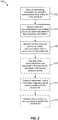
- FIG. 2 includes a method 200 for receiving communications from different serving cells.
- Method 200 includes, at Block 202, receiving scheduling information for downlink transmissions from a first cell in the active set.
- UE 102 can include a downlink communicating component 412, as described in FIG. 4 operable for receiving the scheduling information for the downlink transmissions from the first cell, as described further herein.
- UE 102 can receive the scheduling information using a receiver of the UE 102 adapted to receive signals from the one or more base stations 104 and 106 over one or more antennas, as described further herein.
- downlink communicating component 412 in FIG. 4 can include such a receiver for receiving scheduling information and other downlink transmissions.
- FIG. 4 can include such a receiver for receiving scheduling information and other downlink transmissions.
- the first cell can correspond to a cell provided by the macro cell base station 104, which can be a downlink serving cell for the UE 102.
- macro cell base station 104 can schedule downlink transmissions for the UE 102 in the serving cell over downlink channel 110 by transmitting scheduling information over the downlink channel 110 to indicate resources over which the macro cell base station 104 and/or small cell base station 106 transmit data on respective downlink channels 110 and 112.
- a downlink serving cell base station 404 which can correspond to the macro cell base station 104 in FIG. 1 , can include a downlink transmission scheduling component 420 for transmitting the scheduling information.
- the UE 102 can obtain the scheduling information (e.g., via the downlink communicating component 412) for receiving downlink communications from the macro cell base station 104 and the small cell base station 106 (and/or other cells that may be in the UE 102 active set) in the serving cell over the downlink channel 110 (e.g., via the downlink communicating component 412).
- the scheduling information e.g., via the downlink communicating component 412
- the small cell base station 106 and/or other cells that may be in the UE 102 active set
- Method 200 also includes, at Block 204, receiving downlink communications from multiple cells in an active set based on the scheduling information.
- Downlink communicating component 412 of UE 102 depicted in FIG. 4 can be operable for receiving the downlink communications from the multiple cells.
- UE 102 receives downlink wireless communications from macro cell base station 104, as indicated over downlink channel at 110, and from small cell base station 106, as indicated at 112.
- macro cell base station 104 can provide a downlink channel 110 to the UE 102 to transmit data to the UE 102
- small cell base station 106 similarly provides a downlink channel 112, where information regarding the channel is indicated by the macro cell base station 104 in the scheduling information.
- base stations 104 and 106 can simultaneously transmit to UE 102 over the downlink channels 110 and 112 to provide improved wireless communications to the UE 102. This can include transmitting substantially the same communications over substantially the same frequency and/or at substantially the same time, for example, to achieve a higher data rate than from a single cell. It is to be appreciated that base stations 104 and 106 can transmit signals to the UE 102 using a transmitter of the base stations 104 and 106 adapted to transmit signals over one or more antennas for receiving by the UE 102.
- Method 200 also includes, at Block 206, receiving serving resource grants for uplink communications from a second cell in the active set.
- downlink communicating component 412 of the UE 102 can be operable for receiving the serving resource grants from a uplink serving cell base station 406, which can be correlated to the small cell base station 106.
- the second cell can correspond to a cell provided by the small cell base station 106.
- small cell base station 106 can also provide serving resource grants to the UE 102 for establishing an uplink channel 114 for UE 102 to communicate with the small cell base station 106.
- Block 302 may be performed at the serving cell based at least in part on comparing radio conditions of the UE 102 uplink measured in the cell, and determining the conditions are less than a threshold, which can result in reassigning the uplink serving cell of the UE 102. For example, this can be performed by uplink serving cell assigning component 424 at downlink serving cell base station 404 in FIG. 4 , which can correlate to the macro cell base station 104.
- Uplink serving cell base station 406 can be assigned as the uplink serving cell for UE 102. For example, this can occur upon initialization of the UE 102 in the wireless network, at a point in time where certain radio conditions are detected relating to the UE 102, and/or the like (e.g., as described in Blocks 302 and 304 of method 300 in FIG. 3 ).
- the downlink serving cell provided by downlink serving cell base station 404 can initially be assigned as the uplink serving cell of the UE 102.
- uplink serving cell assigning component 424 can detect that radio conditions of the uplink from the UE 102 at the downlink serving cell have degraded to be less than a threshold level.
- non-serving grant component 422 of the downlink serving cell base station 404 can generate non-serving grant information and can communicate the non-serving grant information, which is received by the downlink communicating component 412 for updating utilization of a related uplink serving resource grant (e.g., as described in Block 204 of method 200 in FIG. 2 ). As described, non-serving grant component 422 can communicate this information to the UE 102 over an E-RGCH in HSPA. Because the base station with desirable uplink radio conditions provides the uplink serving cell for the UE 102, non-serving grants from other base stations that lower the rate/power of the UE 102 will likely have very little, if any, impact on uplink communications between the UE 102 and its uplink serving cell.
- rate/power controlling component 416 can specify rate/power controlling information for the uplink resource grant to uplink serving cell base station 406 (e.g., as described in Block 208 of method 200 in FIG. 2 ).
- Rate/power information receiving component 434 can obtain the rate/power controlling information from UE 102 (e.g., as described in Block 312 of method 300 in FIG. 3 ).
- Serving grant component 430 can use the rate/power information from the UE 102 to set rate/power of the uplink serving grant resources for the UE 102.
- serving grant component 430 can communicate rate/power parameters for the uplink serving grant resource over an F-DPCH in HSPA.
- Uplink communicating component 414 can receive the parameters, and can establish or modify the uplink channel with the uplink serving cell base station 406, and/or transmission sent over the channel by uplink communicating component 414, based at least in part on the parameters.
- the processor 504 is responsible for managing the bus 502 and general processing, including the execution of software stored on the computer-readable medium 506.
- the software when executed by the processor 504, causes the processing system 514 to perform the various functions described infra for any particular apparatus.
- the computer-readable medium 506 may also be used for storing data that is manipulated by the processor 504 when executing software.
- processor 504, computer-readable medium 506, or a combination of both may be configured or otherwise specially programmed to perform the functionality of the active set managing component 410, downlink communicating component 412, uplink communicating component 414, or various other components described herein.
- processor 504, computer-readable medium 506, or a combination of both may be configured or otherwise specially programmed to perform the functionality of the downlink transmission scheduling component 420, non-serving grant component 422, or uplink serving cell assigning component 424 of the downlink serving cell base station 404, serving grant component 430, uplink transmission receiving component 432, or rate/power information receiving component 434 of uplink serving cell base station 406, uplink serving cell assigning component 440 of RNC 408, and/or the like.
- a UMTS network includes three interacting domains: a Core Network (CN) 604, a UMTS Terrestrial Radio Access Network (UTRAN) 602, and User Equipment (UE) 610.
- UE 610 may be similar to UE 102 and configured to include, for example, one or more of the active set managing component 410, downlink communicating component 412, uplink communicating component 414, etc., as described above.
- the UTRAN 602 provides various wireless services including telephony, video, data, messaging, broadcasts, and/or other services.
- Communication between a UE 610 and a Node B 608 may be considered as including a physical (PHY) layer and a medium access control (MAC) layer. Further, communication between a UE 610 and an RNC 606 by way of a respective Node B 608 may be considered as including a radio resource control (RRC) layer.
- RRC radio resource control
- the PHY layer may be considered layer 1; the MAC layer may be considered layer 2; and the RRC layer may be considered layer 3.
- Information hereinbelow utilizes terminology introduced in the RRC Protocol Specification, 3GPP TS 25.331, incorporated herein by reference.
- An air interface for UMTS may utilize a spread spectrum Direct-Sequence Code Division Multiple Access (DS-CDMA) system.
- the spread spectrum DS-CDMA spreads user data through multiplication by a sequence of pseudorandom bits called chips.
- the "wideband" W-CDMA air interface for UMTS is based on such direct sequence spread spectrum technology and additionally calls for a frequency division duplexing (FDD).
- FDD uses a different carrier frequency for the UL and DL between a Node B 608 and a UE 610.
- Another air interface for UMTS that utilizes DS-CDMA, and uses time division duplexing (TDD), is the TD-SCDMA air interface.
- TD-SCDMA time division duplexing
- HSPA air interface includes a series of enhancements to the 3G/W-CDMA air interface, facilitating greater throughput and reduced latency.
- HSPA utilizes hybrid automatic repeat request (HARQ), shared channel transmission, and adaptive modulation and coding.
- HARQ hybrid automatic repeat request
- the standards that define HSPA include HSDPA (high speed downlink packet access) and HSUPA (high speed uplink packet access, also referred to as enhanced uplink, or EUL).
- HSDPA utilizes as its transport channel the high-speed downlink shared channel (HS-DSCH).
- the HS-DSCH is implemented by three physical channels: the high-speed physical downlink shared channel (HS-PDSCH), the high-speed shared control channel (HS-SCCH), and the high-speed dedicated physical control channel (HS-DPCCH).
- HS-PDSCH high-speed physical downlink shared channel
- HS-SCCH high-speed shared control channel
- HS-DPCCH high-speed dedicated physical control channel
- the HS-DPCCH carries the HARQ ACK/NACK signaling on the uplink to indicate whether a corresponding packet transmission was decoded successfully. That is, with respect to the downlink, the UE 610 provides feedback to the node B 608 over the HS-DPCCH to indicate whether it correctly decoded a packet on the downlink.
- HS-DPCCH further includes feedback signaling from the UE 610 to assist the node B 608 in taking the right decision in terms of modulation and coding scheme and precoding weight selection, this feedback signaling including the CQI and PCI.
- HSPA Evolved or HSPA+ is an evolution of the HSPA standard that includes MIMO and 64-QAM, enabling increased throughput and higher performance. That is, in an aspect of the disclosure, the node B 608 and/or the UE 610 may have multiple antennas supporting MIMO technology. The use of MIMO technology enables the node B 608 to exploit the spatial domain to support spatial multiplexing, beamforming, and transmit diversity.
- Spatial multiplexing may be used to transmit different streams of data simultaneously on the same frequency.
- the data steams may be transmitted to a single UE 610 to increase the data rate, or to multiple UEs 610 to increase the overall system capacity. This is achieved by spatially precoding each data stream and then transmitting each spatially precoded stream through a different transmit antenna on the downlink.
- the spatially precoded data streams arrive at the UE(s) 610 with different spatial signatures, which enables each of the UE(s) 610 to recover the one or more the data streams destined for that UE 610.
- each UE 610 may transmit one or more spatially precoded data streams, which enables the node B 608 to identify the source of each spatially precoded data stream.
- Single Input Multiple Output generally refers to a system utilizing a single transmit antenna (a single input to the channel) and multiple receive antennas (multiple outputs from the channel).
- a single transport block is sent over the respective carrier.
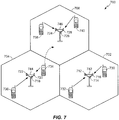
- the UE 734 may maintain communication with one or more of the neighboring cells. During this time, the UE 734 may maintain an Active Set, that is, a list of cells that the UE 734 is simultaneously connected to (i.e., the UTRA cells that are currently assigning a downlink dedicated physical channel (DPCH) or fractional downlink dedicated physical channel (F-DPCH) to the UE 734 may constitute the Active Set).
- an Active Set that is, a list of cells that the UE 734 is simultaneously connected to (i.e., the UTRA cells that are currently assigning a downlink dedicated physical channel (DPCH) or fractional downlink dedicated physical channel (F-DPCH) to the UE 734 may constitute the Active Set).
- DPCH downlink dedicated physical channel
- F-DPCH fractional downlink dedicated physical channel
- the modulation and multiple access scheme employed by the access network 700 may vary depending on the particular telecommunications standard being deployed.
- the standard may include Evolution-Data Optimized (EV-DO) or Ultra Mobile Broadband (UMB).
- EV-DO and UMB are air interface standards promulgated by the 3rd Generation Partnership Project 2 (3GPP2) as part of the CDMA2000 family of standards and employs CDMA to provide broadband Internet access to mobile stations.
- 3GPP2 3rd Generation Partnership Project 2
- the radio protocol architecture may take on various forms depending on the particular application.
- An example for an HSPA system will now be presented with reference to FIG. 8 .
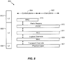
- FIG. 8 is a conceptual diagram illustrating an example of the radio protocol architecture 800 for the user plane 802 and the control plane 804 of a user equipment (UE) or node B/base station.
- architecture 800 may be included in a network entity and/or UE such as an entity within UE 102, a base station 104, 106, 404, 406 ( FIGs. 1 and 4 ), etc.
- the radio protocol architecture 800 for the UE and node B is shown with three layers: Layer 1 806, Layer 2 808, and Layer 3 810. Layer 1 806 is the lowest lower and implements various physical layer signal processing functions. As such, Layer 1 806 includes the physical layer 807.
- Layer 2 (L2 layer) 808 is above the physical layer 807 and is responsible for the link between the UE and node B over the physical layer 807.
- Layer 3 (L3 layer) 810 includes a radio resource control (RRC) sublayer 815.
- the RRC sublayer 815 handles the control plane signaling of Layer 3 between the UE and the UTRAN.
- the L2 layer 808 includes a media access control (MAC) sublayer 809, a radio link control (RLC) sublayer 811, and a packet data convergence protocol (PDCP) 813 sublayer, which are terminated at the node B on the network side.
- MAC media access control
- RLC radio link control
- PDCP packet data convergence protocol
- the UE may have several upper layers above the L2 layer 808 including a network layer (e.g., IP layer) that is terminated at a PDN gateway on the network side, and an application layer that is terminated at the other end of the connection (e.g., far end UE, server, etc.).
- IP layer e.g., IP layer
- the PDCP sublayer 813 provides multiplexing between different radio bearers and logical channels.
- the PDCP sublayer 813 also provides header compression for upper layer data packets to reduce radio transmission overhead, security by ciphering the data packets, and handover support for UEs between node Bs.
- the RLC sublayer 811 provides segmentation and reassembly of upper layer data packets, retransmission of lost data packets, and reordering of data packets to compensate for out-of-order reception due to hybrid automatic repeat request (HARQ).
- HARQ hybrid automatic repeat request
- the MAC sublayer 809 provides multiplexing between logical and transport channels.
- the MAC sublayer 809 is also responsible for allocating the various radio resources (e.g., resource blocks) in one cell among the UEs.
- the MAC sublayer 809 is also responsible for HARQ operations.
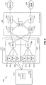
- FIG. 9 is a block diagram of a communication system 900 including a Node B 910 in communication with a UE 950, where Node B 910 may include base stations 104, 106, 404, 406, etc., and the UE 950 may be UE 102 ( FIGs. 1 and 4 ).
- a transmit processor 920 may receive data from a data source 912 and control signals from a controller/processor 940. The transmit processor 920 provides various signal processing functions for the data and control signals, as well as reference signals (e.g., pilot signals).
- a receiver 954 receives the downlink transmission through an antenna 952 and processes the transmission to recover the information modulated onto the carrier.
- the information recovered by the receiver 954 is provided to a receive frame processor 960, which parses each frame, and provides information from the frames to a channel processor 994 and the data, control, and reference signals to a receive processor 970.
- the receive processor 970 then performs the inverse of the processing performed by the transmit processor 920 in the Node B 910. More specifically, the receive processor 970 descrambles and despreads the symbols, and then determines the most likely signal constellation points transmitted by the Node B 910 based on the modulation scheme. These soft decisions may be based on channel estimates computed by the channel processor 994.
- the soft decisions are then decoded and deinterleaved to recover the data, control, and reference signals.
- the CRC codes are then checked to determine whether the frames were successfully decoded.
- the data carried by the successfully decoded frames will then be provided to a data sink 972, which represents applications running in the UE 950 and/or various user interfaces (e.g., display).
- Control signals carried by successfully decoded frames will be provided to a controller/processor 990.
- the controller/processor 990 may also use an acknowledgement (ACK) and/or negative acknowledgement (NACK) protocol to support retransmission requests for those frames.
- ACK acknowledgement
- NACK negative acknowledgement
- the controller/processors 940 and 990 may be used to direct the operation at the Node B 910 and the UE 950, respectively.
- the controller/processors 940 and 990 may provide various functions including timing, peripheral interfaces, voltage regulation, power management, and other control functions.
- the computer-readable media of memories 942 and 992 may store data and software for the Node B 910 and the UE 950, respectively.
- a scheduler/processor 946 at the Node B 910 may be used to allocate resources to the UEs and schedule downlink and/or uplink transmissions for the UEs.
- processor 504 FIG. 5
- processors include microprocessors, microcontrollers, digital signal processors (DSPs), field programmable gate arrays (FPGAs), programmable logic devices (PLDs), state machines, gated logic, discrete hardware circuits, and other suitable hardware configured to perform the various functionality described throughout this disclosure.
- DSPs digital signal processors
- FPGAs field programmable gate arrays
- PLDs programmable logic devices
- state machines gated logic, discrete hardware circuits, and other suitable hardware configured to perform the various functionality described throughout this disclosure.
- One or more processors in the processing system may execute software.
- Software shall be construed broadly to mean instructions, instruction sets, code, code segments, program code, programs, subprograms, software modules, applications, software applications, software packages, routines, subroutines, objects, executables, threads of execution, procedures, functions, etc., whether referred to as software, firmware, middleware, microcode, hardware description language, or otherwise.
- the software may reside on a computer-readable medium 506 ( FIG. 5 ).
- the computer-readable medium 506 ( FIG. 5 ) may be a non-transitory computer-readable medium.
- a non-transitory computer-readable medium includes, by way of example, a magnetic storage device (e.g., hard disk, floppy disk, magnetic strip), an optical disk (e.g., compact disk (CD), digital versatile disk (DVD)), a smart card, a flash memory device (e.g., card, stick, key drive), random access memory (RAM), read only memory (ROM), programmable ROM (PROM), erasable PROM (EPROM), electrically erasable PROM (EEPROM), a register, a removable disk, and any other suitable medium for storing software and/or instructions that may be accessed and read by a computer.
- a magnetic storage device e.g., hard disk, floppy disk, magnetic strip
- an optical disk e.g., compact disk (CD), digital versatile disk (DVD)
- a smart card e.g., a flash memory device (e.g., card, stick, key drive), random access memory (RAM), read only memory (ROM), programmable ROM
Description
- Wireless communication networks are widely deployed to provide various communication services such as telephony, video, data, messaging, broadcasts, and so on. Such networks, which are usually multiple access networks, support communications for multiple users by sharing the available network resources. One example of such a network is the UMTS Terrestrial Radio Access Network (UTRAN). The UTRAN is the radio access network (RAN) defined as a part of the Universal Mobile Telecommunications System (UMTS), a third generation (3G) mobile phone technology supported by the 3rd Generation Partnership Project (3GPP). The UMTS, which is the successor to Global System for Mobile Communications (GSM) technologies, currently supports various air interface standards, such as Wideband-Code Division Multiple Access (W-CDMA), Time Division-Code Division Multiple Access (TD-CDMA), and Time Division-Synchronous Code Division Multiple Access (TD-SCDMA). Another standard can include 3GPP long term evolution (LTE). The UMTS also supports enhanced 3G data communications protocols, such as High Speed Packet Access (HSPA), which provides higher data transfer speeds and capacity to associated UMTS networks.
-
US 2011/249620A1 relates to wireless communication and in particular to wireless communication system using multiple-serving nodes.WO 2011/097523A1 relates to wireless communication and more particularly to resource allocation and transmission for coordinated multi-point transmission. - User equipment (UE) can communicate with multiple cells in an active set over such networks to receive wireless network access. This can increase throughput at the UE by allowing the UE to simultaneously receive downlink communications from the multiple cells in a given network. In current systems, one of the multiple cells is considered the serving cell for managing resources relating to uplink communications from the UE, which is usually the cell with more desirable downlink radio conditions as measured by the UE. In addition, one or more base stations can provide each of the multiple cells, and the base stations are often of different power classes (e.g., macro cell base stations that transmit on the order of 20 Watts (W), pico cell base stations that transmit on the order of 1 W, etc.). UEs, however, transmit uplink communications at a single power, which can result in a power imbalance at the cells.
- For example, the UE can be served by a macro cell provided by a macro cell base station, but the UE can also be closer to a pico cell provided by a pico cell base station. Both cells can be in the active set of the UE such that the UE receives downlink communications from both the macro cell and the pico cell. In this example, the UE is situated such that the stronger power of the macro cell results in better radio conditions at the UE than the pico cell. Thus, though the UE is physically closer to the pico cell, the macro cell is the serving cell for the UE because its downlink power is greater than that of the pico cell (and/or the pathloss from the macro cell to the UE is lower than from the pico cell to the UE). The pico cell, however, may experience better radio conditions for receiving communications from the UE in its current location since the UE is physically closer to the pico cell (and/or the pathloss from the UE to the pico cell is lower than from the UE to the macro cell).
- Furthermore, in some systems, the pico cell can transmit commands to the UE to lower its communication rate/power on uplink resources due to the UE's proximity to the pico cell and because the pico cell is in the UE's active set. Where the UE lowers its communication rate/power over the uplink resources, the macro cell, which is the serving cell for the UE, may receive unreliable uplink communications from the UE. This can impact the UE's ability to reliably communicate data back to the serving cell for providing to a wireless network, for indicating feedback on downlink communication resources, for controlling aspects of an uplink communication grant from the serving cell, etc.
- According to the present invention, a method as set forth in claim 1, an apparatus as set forth in claim 9 and a computer-readable storage medium as set forth in claim 15 are provided. Embodiments of the invention are claimed in the dependent claims. The following presents a simplified summary of one or more aspects in order to provide a basic understanding of such aspects. This summary is not an extensive overview of all contemplated aspects, and is intended to neither identify key or critical elements of all aspects nor delineate the scope of any or all aspects. Its sole purpose is to present some concepts of one or more aspects in a simplified form as a prelude to the more detailed description that is presented later.
- In an aspect, a method of wireless communication of a user equipment (UE) is provided. The method includes receiving scheduling information for one or more downlink transmissions from a first cell in an active set of the UE, receiving downlink wireless communications from multiple cells in an active set, receiving at least one of scheduling information for one or more downlink transmissions or one or more non-serving resource grants from a first cell in the active set, and receiving one or more serving resource grants for uplink communications from a second cell in the active set, transmitting uplink communications over resources of the second cell indicated in the one or more serving resource grants; and transmitting power control information regarding uplink communications to the second cell.
- In another aspect, an apparatus for wireless communication of a UE is provided. The apparatus includes an active set managing component operable for managing wireless communications with a first cell in the active set of , multiple cells in an active set, and a downlink communicating component operable for receiving at least one of scheduling information for one or more downlink transmissions or one or more non-serving resource grants from a first cell in the active set, and for receiving one or more serving resource grants for uplink communications from a second cell in the active set.
- To the accomplishment of the foregoing and related ends, the one or more aspects comprise the features hereinafter fully described and particularly pointed out in the claims. The following description and the annexed drawings set forth in detail certain illustrative features of the one or more aspects. These features are indicative, however, of but a few of the various ways in which the principles of various aspects may be employed, and this description is intended to include all such aspects and their equivalents.
-
-
FIG. 1 is a schematic diagram illustrating an exemplary aspect of communicating with multiple base stations in a wireless communication system; -
FIG. 2 is a flow diagram illustrating an exemplary method for receiving downlink and uplink serving information from multiple cells in a wireless communication system; -
FIG. 3 is a flow diagram illustrating an exemplary method for assigning different downlink and uplink serving cells to a user equipment in a wireless communication system; -
FIG. 4 is a block diagram of an example system for utilizing different downlink and uplink serving cells in a wireless communication system; -
FIG. 5 is a block diagram illustrating an example of a hardware implementation for an apparatus employing a processing system to perform functions described herein; -
FIG. 6 is a block diagram conceptually illustrating an example of a telecommunications system including a UE configured to perform functions described herein; -
FIG. 7 is a conceptual diagram illustrating an example of an access network for use with a UE configured to perform functions described herein; -
FIG. 8 is a conceptual diagram illustrating an example of a radio protocol architecture for the user and control planes for a base station and/or a UE configured to perform functions described herein; and -
FIG. 9 is a block diagram conceptually illustrating an example of a Node B in communication with a UE in a telecommunications system configured to perform functions described herein. - The detailed description set forth below in connection with the appended drawings is intended as a description of various configurations and is not intended to represent the only configurations in which the concepts described herein may be practiced. The detailed description includes specific details for the purpose of providing a thorough understanding of various concepts. However, it will be apparent to those skilled in the art that these concepts may be practiced without these specific details. In some instances, well known structures and components are shown in block diagram form in order to avoid obscuring such concepts.
- Described herein are various aspects related to configuring different serving cells for downlink and uplink communications with a user equipment (UE) in a wireless network. For example, when a UE is situated such that the UE experiences more desirable radio conditions with a first cell than with a second cell for downlink communications, but where the UE also experiences more desirable radio conditions with the second cell than with the first cell for uplink communications, then the first cell can be configured as a serving cell for managing downlink communications to the UE while the second cell can be configured as a serving cell for managing uplink communications from the UE. In one specific example, the UE can receive serving resource grants from the second cell for communicating therewith while receiving scheduled downlink transmission and non-serving resource grants from the first cell.
- Additionally, for example, the UE can communicate rate/power control information for the serving resource grants to the second cell. This allows the second cell to control the rate/power of the serving resource grants to the UE as opposed to the first cell that is the serving cell for downlink communications to the UE. Moreover, for example, the UE can communicate feedback information for the downlink transmissions to the second cell over resources granted by the second cell. Thus, in these examples, the second cell can be the serving cell for managing and receiving uplink communications from the UE when the UE is located such that more desirable uplink radio conditions are experienced between the UE and the second cell as compared to the first cell, while the first cell can remain the serving cell for downlink communications.
- Referring to
FIGs. 1-3 , aspects of the present apparatus and method are depicted with reference to one or more components and one or more methods that may perform the actions or functions described herein. Although the operations described below inFIGs. 2 and3 are presented in a particular order and/or as being performed by an example component, it should be understood that the ordering of the actions and the components performing the actions may be varied, depending on the implementation. Moreover, it should be understood that the following actions or functions may be performed by a specially-programmed processor, a processor executing specially-programmed software or computer-readable media, or by any other combination of a hardware component and/or a software component capable of performing the described actions or functions. - In a particular aspect, a system 100 (
FIG. 1 ) is illustrated for communicating with multiple cells in a wireless network.System 100 includes a UE 102 that communicates with a macrocell base station 104 and a smallcell base station 106 to access a wireless network (not shown). It is to be appreciated that thebase stations cell base station 104 and smallcell base station 106 are also connected to a radio network controller (RNC) or other network component (not shown) of a wireless network to facilitate providing UEs with access to the wireless network. Moreover, for example,UE 102 can support communicating with multiple cells, such that cells of the macrocell base station 104 and the smallcell base station 106 can be in an active set of theUE 102. The active set of a UE is defined to include a set of base stations to which the UE can be simultaneously connected for communicating in the wireless network. For example,UE 102 can receive wireless network communications from the multiple cells in its active set to improve rate and/or throughput of the communications. Similarly,UE 102 may transmit communications to the multiple cells in its active set for such purposes. - A serving cell can be configured for managing downlink and uplink communications with the
UE 102 by providing serving or non-serving resource grants, receiving feedback regarding data received over the grants, receiving and processing uplink communications fromUE 102, and/or the like. In conventional systems, the same cell is selected as the serving cell for both downlink and uplink communications at theUE 102, and typically is selected as the cell with the most optimal downlink radio conditions as compared to other cells and/or a cell with downlink radio conditions measuring at least at a threshold level. In examples described herein, however, theUE 102 can have different serving cells for downlink and uplink communications. - For example,
FIG. 2 includes amethod 200 for receiving communications from different serving cells.Method 200 includes, atBlock 202, receiving scheduling information for downlink transmissions from a first cell in the active set.UE 102 can include adownlink communicating component 412, as described inFIG. 4 operable for receiving the scheduling information for the downlink transmissions from the first cell, as described further herein. It is to be appreciated thatUE 102 can receive the scheduling information using a receiver of theUE 102 adapted to receive signals from the one ormore base stations component 412 inFIG. 4 can include such a receiver for receiving scheduling information and other downlink transmissions. In addition, inFIG. 1 for example, the first cell can correspond to a cell provided by the macrocell base station 104, which can be a downlink serving cell for theUE 102. In this regard, macrocell base station 104 can schedule downlink transmissions for theUE 102 in the serving cell overdownlink channel 110 by transmitting scheduling information over thedownlink channel 110 to indicate resources over which the macrocell base station 104 and/or smallcell base station 106 transmit data onrespective downlink channels FIG. 4 , a downlink servingcell base station 404, which can correspond to the macrocell base station 104 inFIG. 1 , can include a downlinktransmission scheduling component 420 for transmitting the scheduling information. Thus, theUE 102 can obtain the scheduling information (e.g., via the downlink communicating component 412) for receiving downlink communications from the macrocell base station 104 and the small cell base station 106 (and/or other cells that may be in theUE 102 active set) in the serving cell over the downlink channel 110 (e.g., via the downlink communicating component 412). -
Method 200 also includes, atBlock 204, receiving downlink communications from multiple cells in an active set based on the scheduling information. Downlink communicatingcomponent 412 ofUE 102 depicted inFIG. 4 can be operable for receiving the downlink communications from the multiple cells. In addition, as depicted inFIG. 1 ,UE 102 receives downlink wireless communications from macrocell base station 104, as indicated over downlink channel at 110, and from smallcell base station 106, as indicated at 112. For example, as described, macrocell base station 104 can provide adownlink channel 110 to theUE 102 to transmit data to theUE 102, and smallcell base station 106 similarly provides adownlink channel 112, where information regarding the channel is indicated by the macrocell base station 104 in the scheduling information. For example,base stations UE 102 over thedownlink channels UE 102. This can include transmitting substantially the same communications over substantially the same frequency and/or at substantially the same time, for example, to achieve a higher data rate than from a single cell. It is to be appreciated thatbase stations UE 102 using a transmitter of thebase stations UE 102. -
Method 200 also includes, atBlock 206, receiving serving resource grants for uplink communications from a second cell in the active set. For example, downlink communicatingcomponent 412 of theUE 102 can be operable for receiving the serving resource grants from a uplink servingcell base station 406, which can be correlated to the smallcell base station 106. In addition, inFIG. 1 for example, the second cell can correspond to a cell provided by the smallcell base station 106. In this regard, for example, in addition to communicating over thedownlink channel 112 toUE 102 based on communications scheduled by macrocell base station 104, smallcell base station 106 can also provide serving resource grants to theUE 102 for establishing anuplink channel 114 forUE 102 to communicate with the smallcell base station 106. Thus, it is to be appreciated that the serving resource grants can indicate resources over which theUE 102 can establish one or more uplink channels for communicating with the second cell. For instance, smallcell base station 106 can establish theuplink channel 114 withUE 102 via the serving resource grants for receiving communicating from theUE 102 such that the cell provided by smallcell base station 106 becomes the serving cell for uplink communications with theUE 102. In this regard, for example,UE 102 can transmit data to the smallcell base station 106, which can include control data related to the downlink communications simultaneously received from macrocell base station 104 and smallcell base station 106, data for providing to components of the wireless network, and/or the like. - Thus,
UE 102 is served on the downlink by a first cell in the UE active set, while being served on the uplink by a second cell in the UE active set. As described further herein, assignment of different serving cells in this regard may be occur based at least in part on an imbalance between received downlink power at the UE from the first cell and received uplink power at the first cell from the UE, while the received uplink power at the second cell from the UE is greater than that at the first cell. Triggering of assigning different serving cells to a UE is described further herein and can be based on measurement of the different signal powers as reported by base stations of the cells, the UE, etc. For example, the serving downlink cell can be assigned as a cell in the active set of the UE at which the UE experiences downlink radio conditions relative to downlink radio conditions of remaining cells in the active set (e.g., the cell with the most optimal downlink radio conditions). Similarly, the serving uplink cell can be assigned as a cell in the active set of the UE that experiences uplink radio conditions from the UE relative to uplink radio conditions experienced by remaining cells in the active set (e.g., the cell experiencing the most optimal uplink radio conditions with the UE). Thus, in one example as described further herein, the serving downlink cell can be assigned based on UE measurements while the serving uplink cell can be assigned based on cell measurements of the UE. - Thus,
method 200 can optionally include, at 208, transmitting uplink communications over resources of the second cell indicated in the serving resource grants.UE 102 can include anuplink communicating component 414 operable for transmitting over the resources related to the serving resource grants.UE 102 can thus transmit the uplink communications overuplink channel 114 provided by the smallcell base station 106 in the serving resource grants sent to theUE 102. As described above with respect to thebase stations UE 102 can similarly transmit uplink communications using a transmitter adapted to transmit signals over one or more antennas for receiving by one or more antennas (via receivers) at thebase stations component 414 can include such a transmitter. - Moreover,
method 200 can optionally include, at 210, transmitting rate/power control information regarding uplink communications to the second cell. For instance, uplink communicatingcomponent 414 inFIG. 4 can optionally include a rate/power controlling component 416 operable for transmitting the rate/power control information. In this example,UE 102 can transmit this information to the smallcell base station 106 over theuplink channel 114 or another channel provided by the smallcell base station 106. In any case, smallcell base station 106 can adjust the serving resource grants of theuplink channel 114 for theUE 102 based at least in part on the information, as described further herein. - In addition,
method 200 can optionally include, at 212, receiving one or more non-serving resource grants from the first cell. For example, macrocell base station 104 can transmit non-serving resource grants and related information forUE 102 overdownlink channel 110 or a related channel, which theUE 102 can receive overdownlink channel 110 and can accordingly adjust an uplink resource grant from the smallcell base station 106, or transmission over resources related to the uplink resource grant, based on the non-serving grant. As described herein with respect toFIG. 4 , the downlink servingcell base station 404 can optionally include anon-serving grant component 422 for transmitting the non-serving grants. Non-serving grants can be used, for example, to adjust a serving resource grant of an uplink channel (e.g., a rate or power of the grant to mitigate interference from theUE 102 when communicating over the uplink channel). TheUE 102 can receive the non-serving grants (e.g., via downlink communicating component 412) and can accordingly adjust an uplink channel, as described further herein. - In
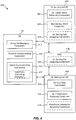
FIG. 3 ,method 300 optionally includes, atBlock 302, comparing radio conditions related to a UE to one or more thresholds. InFIG. 4 , downlink servingcell base station 404, which can correlate to the macrocell base station 104, optionally includes an uplink servingcell assigning component 424 operable for comparing the radio conditions (e.g., in determining whether to reassign an uplink serving cell for the UE 102). In an alternative example,RNC 408 inFIG. 4 optionally includes a uplink servingcell assigning component 440 operable for such purposes, as described further herein. For example, this optional comparison can trigger assigning different cells as serving cells for the uplink and downlink, as described, though it is to be appreciated that different uplink and downlink serving cells can be assigned under substantially any circumstances or events related or unrelated to radio conditions at the serving cell. - When
Block 302 is performed, for example, this comparison can occur at one or more RNCs, such asRNC 308 inFIG. 4 , that communicate with the macrocell base station 104, such as downlink servingcell base station 404, and the smallcell base station 106, such as uplink servingcell base station 406, such to receive uplink radio conditions of theUE 102 at the cells. Where macrocell base station 104 reports radio conditions of theUE 102 uplink (e.g., reference signal code power (RSCP), reference signal received power (RSRP), or similar measured conditions) are less than a threshold (and/or smallcell base station 106 reports radio conditions of theUE 102 uplink that achieve or exceed another threshold), the RNC(s) can trigger reassignment of an uplink serving cell for theUE 102 to small cell base station 106 (e.g., via uplink servingcell assigning component 440, as described herein). In one example, triggering the reassignment can be further based at least in part on determining downlink conditions of the small cell reported by theUE 102 as achieving or exceeding yet another threshold. - In another example,
Block 302, if performed, may be performed at the serving cell based at least in part on comparing radio conditions of theUE 102 uplink measured in the cell, and determining the conditions are less than a threshold, which can result in reassigning the uplink serving cell of theUE 102. For example, this can be performed by uplink servingcell assigning component 424 at downlink servingcell base station 404 inFIG. 4 , which can correlate to the macrocell base station 104. In addition, in this example, the comparing can include comparing radio conditions of smallcell base station 106 reported by theUE 102 to the macrocell base station 104 to determine if these conditions achieve or exceed another threshold, which can additionally or alternatively result in reassigning the uplink serving cell for theUE 102. Therefore, as described, comparison of the radio conditions relative to the one or more thresholds may result in a determination to assign a different cell as the uplink serving cell for theUE 102. - Thus,
method 300 includes, atBlock 304, assigning a different cell as an uplink serving cell for uplink communications with a UE. As described, uplink servingcell assigning component cell base station 404 orRNC 408 inFIG. 4 can be operable for assigning uplink servingcell base station 406 to provide the uplink serving cell forUE 102. In addition, inFIG. 1 for example, smallcell base station 106 can be assigned to provide the uplink serving cell for theUE 102 while macro cell base station continues to provide the downlink serving cell forUE 102. The assigning can be based on the comparing inoptional Block 302 to determine to assign the smallcell base station 106 as the uplink serving cell or otherwise. As described, assigning the smallcell base station 106 to provide the uplink serving cell can include the smallcell base station 106 providing one or more serving resource grants for theuplink channel 114 to theUE 102, while macrocell base station 104 continues to schedule downlink transmissions for theUE 102. - In an example, the macro
cell base station 104 can transmit a communication to small cell base station 106 (e.g., via uplink servingcell assigning component 424 inFIG. 4 ) to indicate that the smallcell base station 106 is to provide the uplink serving cell forUE 102. This communication can occur over a backhaul connection betweenbase stations base stations cell base station 106 can receive the indication from the RNC (e.g., via uplink servingcell assigning component 440 inFIG. 4 ), determine to provide the uplink serving cell for theUE 102 based at least in part on measuring radio conditions of theUE 102 uplink at smallcell base station 106 to determine whether the conditions achieve or exceed a threshold, and/or the like. - In this regard, for example,
method 300 further includes, atBlock 306, scheduling downlink transmissions and/or transmitting non-serving resource grants from the serving cell to the UE. For example, downlink servingcell base station 404 inFIG. 4 includes a downlinktransmission scheduling component 420 and optionally anon-serving grant component 422 operable for respectively scheduling downlink transmissions and transmitting non-serving resource grants, as described further herein. Moreover, for example, downlinktransmission scheduling component 420 andnon-serving grant component 422 can include a transmitter for transmitting the scheduling information and/or the non-serving resource grants.Method 300 also includes, atBlock 308, transmitting one or more serving resource grants from the uplink serving cell to the UE. For example, uplink servingcell base station 406 includes a servinggrant component 430 operable for transmitting the serving resource grants to the UE 102 (e.g., based on being assigned as the uplink serving cell for the UE 102). It is to be appreciated that servinggrant component 430 can include a transmitter for transmitting the serving resource grants to theUE 102, as described further herein. - As described, for example, the macro
cell base station 104 schedules downlink transmissions for theUE 102 to receive from macrocell base station 104 and smallcell base station 106 overdownlink channels 110 and 112 (and/or other downlink channels of other base stations in theUE 102 active set). The macrocell base station 104 can schedule the downlink transmissions usingdownlink channel 110 to communicate related scheduling information to theUE 102, which theUE 102 obtains for determining when to receive transmissions from the cells. The macrocell base station 104 can also transmit non-serving resource grants usingdownlink channel 110 to modify parameters of an uplink of the UE 102 (e.g., a rate/power, etc.), which theUE 102 obtains for modifying an uplink channel with the smallcell base station 106. Moreover, the smallcell base station 106 transmits one or more uplink serving resource grants to the UE 102 (e.g., overdownlink channel 112 or another channel) to allow theUE 102 to establishuplink channel 114 with the smallcell base station 106 based on the uplink serving resource grants. -
Method 300 also optionally includes, atBlock 310, receiving uplink communications from the UE over resources related to the one or more serving resource grants. For example, uplink servingcell base station 406 can include an uplinktransmission receiving component 432 operable for receiving communications from theUE 102 over the resources. For instance, uplinktransmission receiving component 432 can include a receiver for such purposes, as described herein. In addition, inFIG. 1 for example, this can include smallcell base station 106 receiving communications fromUE 102 over theuplink channel 114, as described. - In addition,
method 300 optionally includes, atBlock 312, receiving rate/power control information from the UE for the one or more serving resource grants. For example, uplink servingcell base station 406 can optionally include a rate/powerinformation receiving component 434 operable for receiving the rate/power control information from theUE 102. For instance, rate/powerinformation receiving component 434 can include a receiver for such purposes, as described herein. InFIG. 1 , in this example,UE 102 communicates the rate/power control information to select a rate/power for theuplink channel 114, and smallcell base station 106 can adjust a current uplink channel or serving resource grant or can initiate a new channel or resource grant based at least in part on the rate/power control information received from theUE 102. - In a specific example, macro
cell base station 104 and smallcell base station 106 can communicate withUE 102 using HSPA such that the macrocell base station 104 providesdownlink channel 110 and smallcell base station 106 providesdownlink channel 112 as a high-speed downlink shared channel (HS-DSCH) over which macrocell base station 104 schedules transmissions forUE 102. Thus, macrocell base station 104 continues to schedule the HS-DSCH transmissions, while smallcell base station 106, once being assigned to provide the uplink serving cell, provides the serving enhanced dedicated channel (E-DCH) for theUE 102 for transmitting feedback (e.g., hybrid automatic repeat/request (HARQ) acknowledgement (ACK)/non-acknowledgement (NAK) data, channel quality indicator (CQI) data, etc.) for HS-DSCH or other uplink transport data (e.g., user plane data) for communicating in the wireless network. Thus, smallcell base station 106, in this example, can communicateinformation regarding E-DCH 114 toUE 102 over an enhanced absolute grant channel (E-AGCH), which can be transmitted overdownlink channel 112. - Moreover, in this specific example,
UE 102 can communicate rate/power control information to small cell base station 106 (e.g., over the E-DCH 114), which can relate to controlling rate/power of the serving resource grant forE-DCH 114. Thus, smallcell base station 106 can process the information, and can modify theE-DCH 114 or otherwise assign resources related to theE-DCH 114 by communicating information over a fractional dedicated physical channel (F-DPCH) overdownlink channel 112 based at least in part on the information received regarding controlling the rate/power fromUE 102. Moreover, in an example, the F-DPCH information can be generated based at least in part on one or more radio conditions observed for theUE 102 to set the rate/power based on the radio conditions (e.g., UEs with desirable conditions can transmit at a lower rate/power to avoid causing excessive interference and/or use of radio resources at the small cell base station 106). In this example, because smallcell base station 106 is the serving cell for theuplink E-DCH 114, F-DPCH from the smallcell base station 106 controls rate/power based on information at the more desirable cell for receiving uplink communications from theUE 102. This is opposed to the conventional case where theUE 102 would be served on the uplink as well by macrocell base station 104, and thus F-DPCH information from the smallcell base station 106 may cause theUE 102 to lower rate/power to the point where the macrocell base station 104 no longer reliably receives the E-DCH fromUE 102. -
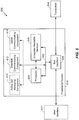
FIG. 4 . Illustrates anexample system 400 for assigning different uplink and downlink serving cells to a UE.System 400 includes aUE 102 for communicating with one or more base stations for accessing a wireless network, as described. For example,UE 102 can communicate with a downlink servingcell base station 404 and/or an uplink servingcell base station 406. In one example, referring additionally toFIG. 1 , the downlink servingcell base station 404 may be macrocell base station 104, and the uplink servingcell base station 406 may be the smallcell base station 106 performing the functions described herein. In addition, thebase stations base stations UE 102. -
UE 102 may comprise any type of mobile device, such as, but not limited to, a smartphone, cellular telephone, mobile phone, laptop computer, tablet computer, or other portable networked device that can be a standalone device, tethered to another device (e.g., a modem connected to a computer), and/or the like. In addition,UE 102 may also be referred to by those skilled in the art as a mobile station, a subscriber station, a mobile unit, a subscriber unit, a wireless unit, a remote unit, a mobile device, a mobile communications device, a wireless device, a wireless communications device, a remote device, a mobile subscriber station, an access terminal, a mobile terminal, a wireless terminal, a remote terminal, a handset, a terminal, a user agent, a mobile client, a client, or some other suitable terminology. In general,UE 102 may be small and light enough to be considered portable and may be configured to communicate wirelessly via an over-the-air (OTA) communication link using one or more OTA communication protocols described herein. Additionally, in some examples,UE 102 may be configured to facilitate communication on multiple separate networks via multiple separate subscriptions, multiple radio links, and/or the like. - Furthermore, downlink serving
cell base station 404 and uplink servingcell base station 406 may comprise one or more of any type of network module, such as an access point, a macro base station (BS), Node B, eNodeB (eNB), a relay, a peer-to-peer device, or substantially any device that can access wireless network components (e.g., an authentication, authorization and accounting (AAA) server, a mobile switching center (MSC), a mobility management entity (MME), a radio network controller (RNC), one or more gateways, etc.). -
UE 102 includes an activeset managing component 410 for storing information regarding an active set at theUE 102, which may include downlink servingcell base station 404 and uplink servingcell base station 406 from which theUE 102 can simultaneously receive communications in a wireless network.UE 102 can also include adownlink communicating component 412 for receiving downlink communications from one or more base stations (e.g., using a receiver, as described further herein), and anuplink communicating component 414 for transmitting communications to one or more base stations (e.g., using a transmitter, as described further herein). Uplink communicatingcomponent 414 can also include a rate/power controlling component 416 for communicating information for controlling rate/power of uplink resources from an uplink servingcell base station 406. - Downlink serving
cell base station 404 can include a downlinktransmission scheduling component 420 for scheduling downlink transmissions from downlink servingcell base station 404 an other base stations in a UE's active set, such asUE 102, an optionalnon-serving grant component 422 for communicating non-serving grants (e.g., relative grants over an enhanced relative grant channel (E-RGCH) in HSPA) to the UE, and/or an optional uplink servingcell assigning component 424 for assigning a different cell provided by a different base station as an uplink serving cell for the UE. - Uplink serving
cell base station 406 can include a servinggrant component 430 for communicating serving resource grants (e.g., absolute grants over E-AGCH in HSPA) to a UE, such asUE 102, an uplinktransmission receiving component 432 for receiving uplink communications from the UE over resources related to the serving resource grant, and/or an optional rate/powerinformation receiving component 434 for obtaining rate/power information related to assigning the granted resources to the UE. -
RNC 408 may optionally include the uplink servingcell assigning component 440, for example, for switching an uplink serving cell of a UE to be different from a downlink serving cell of the UE. As described, this functionality can exist in theRNC 408 or in the downlink serving cell base station 404 (or substantially any component of the wireless network that can communicate with one or more base stations). - According to an example, active
set managing component 410 can store information regarding an active set for theUE 102, which can include information regarding downlink servingcell base station 404 and uplink servingcell base station 406, from whichUE 102 can simultaneously receive downlink communications in a wireless network. AsUE 102 moves throughout a network, for example, activeset managing component 410 can add and remove cells from the active set of theUE 102 based on detected radio conditions of the cells and/or whether theUE 102 ceases or initiates communications with the cells. In any case, as described,downlink communicating component 412 can simultaneously receive downlink communications from multiple cells in the active set (e.g., as described instep 202 ofmethod 200 inFIG. 2 ). - Downlink serving
cell base station 404 can be assigned as the downlink serving cell for the UE 102 (e.g., based on radio conditions at the downlink serving cell provided by downlink serving cell base station 404). Thus, downlinktransmission scheduling component 420 can schedule downlink transmissions from the cells in theUE 102 active set (e.g., as described instep 306 ofmethod 300 inFIG. 3 ). Downlink communicatingcomponent 412 of theUE 102 can receive scheduling information from the downlink servingcell base station 404 in this regard, and can receive the downlink transmissions simultaneously from the cells in the active set of the UE 102 (e.g., as described instep 204 ofmethod 200 inFIG. 2 ). - Uplink serving
cell base station 406 can be assigned as the uplink serving cell forUE 102. For example, this can occur upon initialization of theUE 102 in the wireless network, at a point in time where certain radio conditions are detected relating to theUE 102, and/or the like (e.g., as described inBlocks method 300 inFIG. 3 ). Thus, in one example, the downlink serving cell provided by downlink servingcell base station 404 can initially be assigned as the uplink serving cell of theUE 102. In this example, uplink servingcell assigning component 424 can detect that radio conditions of the uplink from theUE 102 at the downlink serving cell have degraded to be less than a threshold level. For example, uplink servingcell assigning component 424 can detect the degradation based at least in part on comparing a RSCP, RSRP, or similar measurements of signals received from theUE 102 with threshold values to determine if the measured value is less than (or equal to in some examples) the threshold value. If so, uplink servingcell assigning component 424 can reassign another cell in theUE 102 active set as the uplink serving cell for theUE 102. - For example, uplink serving
cell assigning component 424 can assign a remaining cell in the active set as the uplink serving cell, assign a cell based at least in part on reported measurements thereof (e.g., based on a measurement report, which can include measurements of the uplink servingcell base station 406, such as RSCP, RSRP, etc., as reported by the UE 102), assign a cell based on measurements reported by the cell (e.g., similar measurements of theUE 102 uplink reported over a backhaul, viaRNC 408, etc.), and/or the like. In an example, uplink servingcell assigning component 424 may assign another cell as the uplink serving cell where the measurements of theUE 102 uplink are less than a threshold and where reported measurements from theUE 102 and/or from the another cell achieve or exceed another threshold. - In another example, uplink serving
cell assigning component 440 at theRNC 408 can reassign an uplink serving cell for theUE 102. In this example, uplink servingcell assigning component 440 can receive measurements of theUE 102 uplink from downlink servingcell base station 404, uplink servingcell base station 406, and/or other base stations in the active set of theUE 102. In this regard, uplink servingcell assigning component 440 can determine whether to assign a different uplink serving cell to theUE 102 where the measurements of theUE 102 at downlink servingcell base station 404 are less than a threshold while measurements of theUE 102 at uplink servingcell base station 406 or another base station achieve or exceed another threshold. In another example, uplink servingcell assigning component 440 can determine whether to assign a different uplink serving cell to theUE 102 where the difference in measurements of theUE 102 uplink at downlink servingcell base station 404 and uplink servingcell base station 406 achieves or exceeds a threshold. - In any case, when the uplink serving
cell base station 406 is reassigned as the uplink serving cell for theUE 102, servinggrant component 430 can communicate a serving grant to theUE 102 for facilitate uplink communications (e.g., as described inBlock 306 ofmethod 300 inFIG. 3 ). For example, the serving grant can relate to an uplink communication channel, such as E-DCH in HSPA. Downlink communicatingcomponent 412 can receive the serving grant from the uplink serving cell base station 406 (e.g., as described inBlock 206 ofmethod 200 inFIG. 2 ). In this regard, uplink communicatingcomponent 414 can establish the uplink channel with the uplink serving cell base station 406 (e.g.,uplink channel 114 inFIG. 1 ), and can transmit uplink communications to the uplink servingcell base station 406 while receiving scheduling information for downlink transmissions and/or non-serving grants from downlink serving cell base station 404 (e.g., as described inBlock 208 ofmethod 200 inFIG. 2 ). Uplinktransmission receiving component 432 can receive the uplink communications fromUE 102 over the uplink channel (e.g., as described inBlock 308 ofmethod 300 inFIG. 3 ). The uplink communications can relate to control data for the downlink transmissions received from downlink servingcell base station 404 and uplink servingcell base station 406, transport data (e.g., user plane data) for communicating to one or more wireless network components, and/or the like. - Moreover, in this regard,
non-serving grant component 422 of the downlink servingcell base station 404 can generate non-serving grant information and can communicate the non-serving grant information, which is received by thedownlink communicating component 412 for updating utilization of a related uplink serving resource grant (e.g., as described inBlock 204 ofmethod 200 inFIG. 2 ). As described,non-serving grant component 422 can communicate this information to theUE 102 over an E-RGCH in HSPA. Because the base station with desirable uplink radio conditions provides the uplink serving cell for theUE 102, non-serving grants from other base stations that lower the rate/power of theUE 102 will likely have very little, if any, impact on uplink communications between theUE 102 and its uplink serving cell. - In addition, in an example, rate/
power controlling component 416 can specify rate/power controlling information for the uplink resource grant to uplink serving cell base station 406 (e.g., as described inBlock 208 ofmethod 200 inFIG. 2 ). Rate/powerinformation receiving component 434 can obtain the rate/power controlling information from UE 102 (e.g., as described inBlock 312 ofmethod 300 inFIG. 3 ). Servinggrant component 430 can use the rate/power information from theUE 102 to set rate/power of the uplink serving grant resources for theUE 102. In one example, servinggrant component 430 can communicate rate/power parameters for the uplink serving grant resource over an F-DPCH in HSPA. Uplink communicatingcomponent 414 can receive the parameters, and can establish or modify the uplink channel with the uplink servingcell base station 406, and/or transmission sent over the channel byuplink communicating component 414, based at least in part on the parameters. -
FIG. 5 is a block diagram illustrating an example of a hardware implementation for anapparatus 500 employing aprocessing system 514.Apparatus 500 may be configured to include, for example, one of UE 102 (FIGs. 1 and4 ), macrocell base station 104 or downlink serving cell base station 404 (FIGs. 1 and4 ), smallcell base station 106 or uplink serving cell base station 406 (FIGs. 1 and4 ), RNC 408 (FIG. 4 ), etc.Apparatus 500 is depicted as including components ofUE 102, including activeset managing component 410,downlink communicating component 412, uplink communicatingcomponent 414, etc., as described above. It is to be appreciated thatapparatus 500 can additionally or alternatively include one or more of the components of downlink servingcell base station 404, uplink servingcell base station 406, orRNC 408, each as described above with respect toFIG. 4 ; the components ofUE 102 are shown for ease of explanation. - In this example, the
processing system 514 may be implemented with a bus architecture, represented generally by thebus 502. Thebus 502 may include any number of interconnecting buses and bridges depending on the specific application of theprocessing system 514 and the overall design constraints. Thebus 502 links together various circuits including one or more processors, represented generally by theprocessor 504, and computer-readable media, represented generally by the computer-readable medium 506. Thebus 502 may also link various other circuits such as timing sources, peripherals, voltage regulators, and power management circuits, which are well known in the art, and therefore, will not be described any further. Abus interface 508 provides an interface between thebus 502 and atransceiver 510. Thetransceiver 510 provides a means for communicating with various other apparatus over a transmission medium, and may include a receiver and/or transmitter, as described further herein. Depending upon the nature of the apparatus, a user interface 512 (e.g., keypad, display, speaker, microphone, joystick) may also be provided. - The
processor 504 is responsible for managing thebus 502 and general processing, including the execution of software stored on the computer-readable medium 506. The software, when executed by theprocessor 504, causes theprocessing system 514 to perform the various functions described infra for any particular apparatus. The computer-readable medium 506 may also be used for storing data that is manipulated by theprocessor 504 when executing software. - In an aspect,
processor 504, computer-readable medium 506, or a combination of both may be configured or otherwise specially programmed to perform the functionality of the activeset managing component 410,downlink communicating component 412, uplink communicatingcomponent 414, or various other components described herein. For example,processor 504, computer-readable medium 506, or a combination of both may be configured or otherwise specially programmed to perform the functionality of the downlinktransmission scheduling component 420,non-serving grant component 422, or uplink servingcell assigning component 424 of the downlink servingcell base station 404, servinggrant component 430, uplinktransmission receiving component 432, or rate/powerinformation receiving component 434 of uplink servingcell base station 406, uplink servingcell assigning component 440 ofRNC 408, and/or the like. - The various concepts presented throughout this disclosure may be implemented across a broad variety of telecommunication systems, network architectures, and communication standards.
- Referring to
FIG. 6 , by way of example and without limitation, the aspects of the present disclosure are presented with reference to aUMTS system 600 employing a W-CDMA air interface. A UMTS network includes three interacting domains: a Core Network (CN) 604, a UMTS Terrestrial Radio Access Network (UTRAN) 602, and User Equipment (UE) 610.UE 610 may be similar toUE 102 and configured to include, for example, one or more of the activeset managing component 410,downlink communicating component 412, uplink communicatingcomponent 414, etc., as described above. In this example, theUTRAN 602 provides various wireless services including telephony, video, data, messaging, broadcasts, and/or other services. TheUTRAN 602 may include a plurality of Radio Network Subsystems (RNSs) such as anRNS 607, each controlled by a respective Radio Network Controller (RNC) such as anRNC 606. Here, theUTRAN 602 may include any number ofRNCs 606 andRNSs 607 in addition to theRNCs 606 andRNSs 607 illustrated herein. TheRNC 606 is an apparatus responsible for, among other things, assigning, reconfiguring and releasing radio resources within theRNS 607. TheRNC 606 may be interconnected to other RNCs (not shown) in theUTRAN 602 through various types of interfaces such as a direct physical connection, a virtual network, or the like, using any suitable transport network. - Communication between a
UE 610 and aNode B 608 may be considered as including a physical (PHY) layer and a medium access control (MAC) layer. Further, communication between aUE 610 and anRNC 606 by way of arespective Node B 608 may be considered as including a radio resource control (RRC) layer. In the instant specification, the PHY layer may be considered layer 1; the MAC layer may be considered layer 2; and the RRC layer may be considered layer 3. Information hereinbelow utilizes terminology introduced in the RRC Protocol Specification, 3GPP TS 25.331, incorporated herein by reference. In addition, theNode Bs 608 can include one or more of the macrocell base station 104 or downlink servingcell base station 404, the smallcell base station 106 or uplink servingcell base station 406, etc., as described herein, and thus may include one or more of the downlinktransmission scheduling component 420,non-serving grant component 422, uplink servingcell assigning component 424, servinggrant component 430, uplinktransmission receiving component 432, rate/powerinformation receiving component 434, etc. Furthermore, in an example,RNC 606 can includeRNC 408, and thus may include an uplink servingcell assigning component 440, as described. - The geographic region covered by the
RNS 607 may be divided into a number of cells, such as including serving cells provided by thebase stations Node Bs 608 are shown in eachRNS 607; however, theRNSs 607 may include any number of wireless Node Bs. TheNode Bs 608 provide wireless access points to aCN 604 for any number of mobile apparatuses. Examples of a mobile apparatus include a cellular phone, a smart phone, a session initiation protocol (SIP) phone, a laptop, a notebook, a netbook, a smartbook, a personal digital assistant (PDA), a satellite radio, a global positioning system (GPS) device, a multimedia device, a video device, a digital audio player (e.g., MP3 player), a camera, a game console, or any other similar functioning device. TheUE 610 is commonly referred to as a UE in UMTS applications, but may also be referred to by those skilled in the art as a mobile station, a subscriber station, a mobile unit, a subscriber unit, a wireless unit, a remote unit, a mobile device, a wireless device, a wireless communications device, a remote device, a mobile subscriber station, an access terminal, a mobile terminal, a wireless terminal, a remote terminal, a handset, a terminal, a user agent, a mobile client, a client, or some other suitable terminology. In a UMTS system, theUE 610 may further include a universal subscriber identity module (USIM) 611, which contains a user's subscription information to a network. For illustrative purposes, oneUE 610 is shown in communication with a number of theNode Bs 608. The DL, also called the forward link, refers to the communication link from aNode B 608 to aUE 610, and the UL, also called the reverse link, refers to the communication link from aUE 610 to aNode B 608. - The
CN 604 interfaces with one or more access networks, such as theUTRAN 602. As shown, theCN 604 is a GSM core network. However, as those skilled in the art will recognize, the various concepts presented throughout this disclosure may be implemented in a RAN, or other suitable access network, to provide UEs with access to types of CNs other than GSM networks. - The
CN 604 includes a circuit-switched (CS) domain and a packet-switched (PS) domain. Some of the circuit-switched elements are a Mobile services Switching Centre (MSC), a Visitor location register (VLR) and a Gateway MSC. Packet-switched elements include a Serving GPRS Support Node (SGSN) and a Gateway GPRS Support Node (GGSN). Some network elements, like EIR, HLR, VLR and AuC may be shared by both of the circuit-switched and packet-switched domains. In the illustrated example, theCN 604 supports circuit-switched services with aMSC 612 and aGMSC 614. In some applications, theGMSC 614 may be referred to as a media gateway (MGW). One or more RNCs, such as theRNC 606, may be connected to theMSC 612. TheMSC 612 is an apparatus that controls call setup, call routing, and UE mobility functions. TheMSC 612 also includes a VLR that contains subscriber-related information for the duration that a UE is in the coverage area of theMSC 612. TheGMSC 614 provides a gateway through theMSC 612 for the UE to access a circuit-switchednetwork 616. TheGMSC 614 includes a home location register (HLR) 615 containing subscriber data, such as the data reflecting the details of the services to which a particular user has subscribed. The HLR is also associated with an authentication center (AuC) that contains subscriber-specific authentication data. When a call is received for a particular UE, theGMSC 614 queries theHLR 615 to determine the UE's location and forwards the call to the particular MSC serving that location. - The
CN 604 also supports packet-data services with a serving GPRS support node (SGSN) 618 and a gateway GPRS support node (GGSN) 620. GPRS, which stands for General Packet Radio Service, is designed to provide packet-data services at speeds higher than those available with standard circuit-switched data services. TheGGSN 620 provides a connection for theUTRAN 602 to a packet-basednetwork 622. The packet-basednetwork 622 may be the Internet, a private data network, or some other suitable packet-based network. The primary function of theGGSN 620 is to provide theUEs 610 with packet-based network connectivity. Data packets may be transferred between theGGSN 620 and theUEs 610 through theSGSN 618, which performs primarily the same functions in the packet-based domain as theMSC 612 performs in the circuit-switched domain. - An air interface for UMTS may utilize a spread spectrum Direct-Sequence Code Division Multiple Access (DS-CDMA) system. The spread spectrum DS-CDMA spreads user data through multiplication by a sequence of pseudorandom bits called chips. The "wideband" W-CDMA air interface for UMTS is based on such direct sequence spread spectrum technology and additionally calls for a frequency division duplexing (FDD). FDD uses a different carrier frequency for the UL and DL between a
Node B 608 and aUE 610. Another air interface for UMTS that utilizes DS-CDMA, and uses time division duplexing (TDD), is the TD-SCDMA air interface. Those skilled in the art will recognize that although various examples described herein may refer to a W-CDMA air interface, the underlying principles may be equally applicable to a TD-SCDMA air interface. - An HSPA air interface includes a series of enhancements to the 3G/W-CDMA air interface, facilitating greater throughput and reduced latency. Among other modifications over prior releases, HSPA utilizes hybrid automatic repeat request (HARQ), shared channel transmission, and adaptive modulation and coding. The standards that define HSPA include HSDPA (high speed downlink packet access) and HSUPA (high speed uplink packet access, also referred to as enhanced uplink, or EUL).
- HSDPA utilizes as its transport channel the high-speed downlink shared channel (HS-DSCH). The HS-DSCH is implemented by three physical channels: the high-speed physical downlink shared channel (HS-PDSCH), the high-speed shared control channel (HS-SCCH), and the high-speed dedicated physical control channel (HS-DPCCH).
- Among these physical channels, the HS-DPCCH carries the HARQ ACK/NACK signaling on the uplink to indicate whether a corresponding packet transmission was decoded successfully. That is, with respect to the downlink, the
UE 610 provides feedback to thenode B 608 over the HS-DPCCH to indicate whether it correctly decoded a packet on the downlink. - HS-DPCCH further includes feedback signaling from the
UE 610 to assist thenode B 608 in taking the right decision in terms of modulation and coding scheme and precoding weight selection, this feedback signaling including the CQI and PCI. - "HSPA Evolved" or HSPA+ is an evolution of the HSPA standard that includes MIMO and 64-QAM, enabling increased throughput and higher performance. That is, in an aspect of the disclosure, the
node B 608 and/or theUE 610 may have multiple antennas supporting MIMO technology. The use of MIMO technology enables thenode B 608 to exploit the spatial domain to support spatial multiplexing, beamforming, and transmit diversity. - Multiple Input Multiple Output (MIMO) is a term generally used to refer to multi-antenna technology, that is, multiple transmit antennas (multiple inputs to the channel) and multiple receive antennas (multiple outputs from the channel). MIMO systems generally enhance data transmission performance, enabling diversity gains to reduce multipath fading and increase transmission quality, and spatial multiplexing gains to increase data throughput.
- Spatial multiplexing may be used to transmit different streams of data simultaneously on the same frequency. The data steams may be transmitted to a
single UE 610 to increase the data rate, or tomultiple UEs 610 to increase the overall system capacity. This is achieved by spatially precoding each data stream and then transmitting each spatially precoded stream through a different transmit antenna on the downlink. The spatially precoded data streams arrive at the UE(s) 610 with different spatial signatures, which enables each of the UE(s) 610 to recover the one or more the data streams destined for thatUE 610. On the uplink, eachUE 610 may transmit one or more spatially precoded data streams, which enables thenode B 608 to identify the source of each spatially precoded data stream. - Spatial multiplexing may be used when channel conditions are good. When channel conditions are less favorable, beamforming may be used to focus the transmission energy in one or more directions, or to improve transmission based on characteristics of the channel. This may be achieved by spatially precoding a data stream for transmission through multiple antennas. To achieve good coverage at the edges of the cell, a single stream beamforming transmission may be used in combination with transmit diversity.
- Generally, for MIMO systems utilizing n transmit antennas, n transport blocks may be transmitted simultaneously over the same carrier utilizing the same channelization code. Note that the different transport blocks sent over the n transmit antennas may have the same or different modulation and coding schemes from one another.
- On the other hand, Single Input Multiple Output (SIMO) generally refers to a system utilizing a single transmit antenna (a single input to the channel) and multiple receive antennas (multiple outputs from the channel). Thus, in a SIMO system, a single transport block is sent over the respective carrier.
- Referring to
FIG. 7 , anaccess network 700 in a UTRAN architecture is illustrated. The multiple access wireless communication system includes multiple cellular regions (cells), includingcells cell 702,antenna groups cell 704,antenna groups cell 706,antenna groups cells cell UEs Node B 742,UEs Node B 744, andUEs Node B 746. Here, eachNode B FIG. 6 ) for all theUEs respective cells UEs UE 102, described above, andNode Bs cell base station 104 or downlink servingcell base station 404, smallcell base station 106 or uplink servingcell base station 406, etc. - As the
UE 734 moves from the illustrated location incell 704 intocell 706, a serving cell change (SCC) or handover may occur in which communication with theUE 734 transitions from thecell 704, which may be referred to as the source cell, tocell 706, which may be referred to as the target cell. Management of the handover procedure may take place at theUE 734, at the Node Bs corresponding to the respective cells, at aradio network controller 408 or 606 (seeFIGs. 4 and6 ), or at another suitable node in the wireless network. For example, during a call with thesource cell 704, or at any other time, theUE 734 may monitor various parameters of thesource cell 704 as well as various parameters of neighboring cells such ascells UE 734 may maintain communication with one or more of the neighboring cells. During this time, theUE 734 may maintain an Active Set, that is, a list of cells that theUE 734 is simultaneously connected to (i.e., the UTRA cells that are currently assigning a downlink dedicated physical channel (DPCH) or fractional downlink dedicated physical channel (F-DPCH) to theUE 734 may constitute the Active Set). - The modulation and multiple access scheme employed by the
access network 700 may vary depending on the particular telecommunications standard being deployed. By way of example, the standard may include Evolution-Data Optimized (EV-DO) or Ultra Mobile Broadband (UMB). EV-DO and UMB are air interface standards promulgated by the 3rd Generation Partnership Project 2 (3GPP2) as part of the CDMA2000 family of standards and employs CDMA to provide broadband Internet access to mobile stations. The standard may alternately be Universal Terrestrial Radio Access (UTRA) employing Wideband-CDMA (W-CDMA) and other variants of CDMA, such as TD-SCDMA; Global System for Mobile Communications (GSM) employing TDMA; and Evolved UTRA (E-UTRA), Ultra Mobile Broadband (UMB), and Flash-OFDM employing OFDMA. UTRA, E-UTRA, UMTS, LTE, LTE Advanced, and GSM are described in documents from the 3GPP organization. CDMA2000 and UMB are described in documents from the 3GPP2 organization. The actual wireless communication standard and the multiple access technology employed will depend on the specific application and the overall design constraints imposed on the system. - The radio protocol architecture may take on various forms depending on the particular application. An example for an HSPA system will now be presented with reference to
FIG. 8 . -
FIG. 8 is a conceptual diagram illustrating an example of theradio protocol architecture 800 for theuser plane 802 and thecontrol plane 804 of a user equipment (UE) or node B/base station. For example,architecture 800 may be included in a network entity and/or UE such as an entity withinUE 102, abase station FIGs. 1 and4 ), etc. Theradio protocol architecture 800 for the UE and node B is shown with three layers: Layer 1 806, Layer 2 808, and Layer 3 810. Layer 1 806 is the lowest lower and implements various physical layer signal processing functions. As such, Layer 1 806 includes thephysical layer 807. Layer 2 (L2 layer) 808 is above thephysical layer 807 and is responsible for the link between the UE and node B over thephysical layer 807. Layer 3 (L3 layer) 810 includes a radio resource control (RRC)sublayer 815. TheRRC sublayer 815 handles the control plane signaling of Layer 3 between the UE and the UTRAN. - In the user plane, the L2 layer 808 includes a media access control (MAC)
sublayer 809, a radio link control (RLC)sublayer 811, and a packet data convergence protocol (PDCP) 813 sublayer, which are terminated at the node B on the network side. Although not shown, the UE may have several upper layers above the L2 layer 808 including a network layer (e.g., IP layer) that is terminated at a PDN gateway on the network side, and an application layer that is terminated at the other end of the connection (e.g., far end UE, server, etc.). - The
PDCP sublayer 813 provides multiplexing between different radio bearers and logical channels. ThePDCP sublayer 813 also provides header compression for upper layer data packets to reduce radio transmission overhead, security by ciphering the data packets, and handover support for UEs between node Bs. TheRLC sublayer 811 provides segmentation and reassembly of upper layer data packets, retransmission of lost data packets, and reordering of data packets to compensate for out-of-order reception due to hybrid automatic repeat request (HARQ). TheMAC sublayer 809 provides multiplexing between logical and transport channels. TheMAC sublayer 809 is also responsible for allocating the various radio resources (e.g., resource blocks) in one cell among the UEs. TheMAC sublayer 809 is also responsible for HARQ operations. -
FIG. 9 is a block diagram of acommunication system 900 including aNode B 910 in communication with aUE 950, whereNode B 910 may includebase stations UE 950 may be UE 102 (FIGs. 1 and4 ). In the downlink communication, a transmitprocessor 920 may receive data from adata source 912 and control signals from a controller/processor 940. The transmitprocessor 920 provides various signal processing functions for the data and control signals, as well as reference signals (e.g., pilot signals). For example, the transmitprocessor 920 may provide cyclic redundancy check (CRC) codes for error detection, coding and interleaving to facilitate forward error correction (FEC), mapping to signal constellations based on various modulation schemes (e.g., binary phase-shift keying (BPSK), quadrature phase-shift keying (QPSK), M-phase-shift keying (M-PSK), M-quadrature amplitude modulation (M-QAM), and the like), spreading with orthogonal variable spreading factors (OVSF), and multiplying with scrambling codes to produce a series of symbols. Channel estimates from achannel processor 944 may be used by a controller/processor 940 to determine the coding, modulation, spreading, and/or scrambling schemes for the transmitprocessor 920. These channel estimates may be derived from a reference signal transmitted by theUE 950 or from feedback from theUE 950. The symbols generated by the transmitprocessor 920 are provided to a transmitframe processor 930 to create a frame structure. The transmitframe processor 930 creates this frame structure by multiplexing the symbols with information from the controller/processor 940, resulting in a series of frames. The frames are then provided to atransmitter 932, which provides various signal conditioning functions including amplifying, filtering, and modulating the frames onto a carrier for downlink transmission over the wireless medium throughantenna 934. Theantenna 934 may include one or more antennas, for example, including beam steering bidirectional adaptive antenna arrays or other similar beam technologies. - At the
UE 950, areceiver 954 receives the downlink transmission through anantenna 952 and processes the transmission to recover the information modulated onto the carrier. The information recovered by thereceiver 954 is provided to a receiveframe processor 960, which parses each frame, and provides information from the frames to achannel processor 994 and the data, control, and reference signals to a receiveprocessor 970. The receiveprocessor 970 then performs the inverse of the processing performed by the transmitprocessor 920 in theNode B 910. More specifically, the receiveprocessor 970 descrambles and despreads the symbols, and then determines the most likely signal constellation points transmitted by theNode B 910 based on the modulation scheme. These soft decisions may be based on channel estimates computed by thechannel processor 994. The soft decisions are then decoded and deinterleaved to recover the data, control, and reference signals. The CRC codes are then checked to determine whether the frames were successfully decoded. The data carried by the successfully decoded frames will then be provided to adata sink 972, which represents applications running in theUE 950 and/or various user interfaces (e.g., display). Control signals carried by successfully decoded frames will be provided to a controller/processor 990. When frames are unsuccessfully decoded by thereceiver processor 970, the controller/processor 990 may also use an acknowledgement (ACK) and/or negative acknowledgement (NACK) protocol to support retransmission requests for those frames. - In the uplink, data from a
data source 978 and control signals from the controller/processor 990 are provided to a transmitprocessor 980. Thedata source 978 may represent applications running in theUE 950 and various user interfaces (e.g., keyboard). Similar to the functionality described in connection with the downlink transmission by theNode B 910, the transmitprocessor 980 provides various signal processing functions including CRC codes, coding and interleaving to facilitate FEC, mapping to signal constellations, spreading with OVSFs, and scrambling to produce a series of symbols. Channel estimates, derived by thechannel processor 994 from a reference signal transmitted by theNode B 910 or from feedback contained in the midamble transmitted by theNode B 910, may be used to select the appropriate coding, modulation, spreading, and/or scrambling schemes. The symbols produced by the transmitprocessor 980 will be provided to a transmitframe processor 982 to create a frame structure. The transmitframe processor 982 creates this frame structure by multiplexing the symbols with information from the controller/processor 990, resulting in a series of frames. The frames are then provided to atransmitter 956, which provides various signal conditioning functions including amplification, filtering, and modulating the frames onto a carrier for uplink transmission over the wireless medium through theantenna 952. - The uplink transmission is processed at the
Node B 910 in a manner similar to that described in connection with the receiver function at theUE 950. Areceiver 935 receives the uplink transmission through theantenna 934 and processes the transmission to recover the information modulated onto the carrier. The information recovered by thereceiver 935 is provided to a receiveframe processor 936, which parses each frame, and provides information from the frames to thechannel processor 944 and the data, control, and reference signals to a receiveprocessor 938. The receiveprocessor 938 performs the inverse of the processing performed by the transmitprocessor 980 in theUE 950. The data and control signals carried by the successfully decoded frames may then be provided to adata sink 939 and the controller/processor, respectively. If some of the frames were unsuccessfully decoded by the receive processor, the controller/processor 940 may also use an acknowledgement (ACK) and/or negative acknowledgement (NACK) protocol to support retransmission requests for those frames. - The controller/
processors Node B 910 and theUE 950, respectively. For example, the controller/processors memories Node B 910 and theUE 950, respectively. A scheduler/processor 946 at theNode B 910 may be used to allocate resources to the UEs and schedule downlink and/or uplink transmissions for the UEs. - Several aspects of a telecommunications system have been presented with reference to a W-CDMA system. As those skilled in the art will readily appreciate, various aspects described throughout this disclosure may be extended to other telecommunication systems, network architectures and communication standards.
- By way of example, various aspects may be extended to other UMTS systems such as TD-SCDMA, High Speed Downlink Packet Access (HSDPA), High Speed Uplink Packet Access (HSUPA), High Speed Packet Access Plus (HSPA+) and TD-CDMA. Various aspects may also be extended to systems employing Long Term Evolution (LTE) (in FDD, TDD, or both modes), LTE-Advanced (LTE-A) (in FDD; TDD, or both modes), CDMA2000, Evolution-Data Optimized (EV-DO), Ultra Mobile Broadband (UMB), IEEE 802.11 (Wi-Fi), IEEE 802.16 (WiMAX), IEEE 802.20, Ultra-Wideband (UWB), Bluetooth, and/or other suitable systems. The actual telecommunication standard, network architecture, and/or communication standard employed will depend on the specific application and the overall design constraints imposed on the system.
- In accordance with various aspects of the disclosure, an element, or any portion of an element, or any combination of elements may be implemented with a "processing system" or processor 504 (
FIG. 5 ) that includes one or more processors. Examples of processors include microprocessors, microcontrollers, digital signal processors (DSPs), field programmable gate arrays (FPGAs), programmable logic devices (PLDs), state machines, gated logic, discrete hardware circuits, and other suitable hardware configured to perform the various functionality described throughout this disclosure. One or more processors in the processing system may execute software. Software shall be construed broadly to mean instructions, instruction sets, code, code segments, program code, programs, subprograms, software modules, applications, software applications, software packages, routines, subroutines, objects, executables, threads of execution, procedures, functions, etc., whether referred to as software, firmware, middleware, microcode, hardware description language, or otherwise. The software may reside on a computer-readable medium 506 (FIG. 5 ). The computer-readable medium 506 (FIG. 5 ) may be a non-transitory computer-readable medium. A non-transitory computer-readable medium includes, by way of example, a magnetic storage device (e.g., hard disk, floppy disk, magnetic strip), an optical disk (e.g., compact disk (CD), digital versatile disk (DVD)), a smart card, a flash memory device (e.g., card, stick, key drive), random access memory (RAM), read only memory (ROM), programmable ROM (PROM), erasable PROM (EPROM), electrically erasable PROM (EEPROM), a register, a removable disk, and any other suitable medium for storing software and/or instructions that may be accessed and read by a computer. The computer-readable medium may also include, by way of example, a carrier wave, a transmission line, and any other suitable medium for transmitting software and/or instructions that may be accessed and read by a computer. The computer-readable medium may be resident in the processing system, external to the processing system, or distributed across multiple entities including the processing system. The computer-readable medium may be embodied in a computer-program product. By way of example, a computer-program product may include a computer-readable medium in packaging materials. Those skilled in the art will recognize how best to implement the described functionality presented throughout this disclosure depending on the particular application and the overall design constraints imposed on the overall system. - It is to be understood that the specific order or hierarchy of steps in the methods disclosed is an illustration of exemplary processes. Based upon design preferences, it is understood that the specific order or hierarchy of steps in the methods may be rearranged. The accompanying method claims present elements of the various steps in a sample order, and are not meant to be limited to the specific order or hierarchy presented unless specifically recited therein.
- The previous description is provided to enable any person skilled in the art to practice the various aspects described herein. Various modifications to these aspects will be readily apparent to those skilled in the art, and the generic principles defined herein may be applied to other aspects. Thus, the claims are not intended to be limited to the aspects shown herein, but is to be accorded the full scope consistent with the language of the claims, wherein reference to an element in the singular is not intended to mean "one and only one" unless specifically so stated, but rather "one or more." Unless specifically stated otherwise, the term "some" refers to one or more. A phrase referring to "at least one of' a list of items refers to any combination of those items, including single members. As an example, "at least one of: a, b, or c" is intended to cover: a; b; c; a and b; a and c; b and c; and a, b and c. All structural and functional equivalents to the elements of the various aspects described throughout this disclosure that are known or later come to be known to those of ordinary skill in the art are expressly incorporated herein by reference and are intended to be encompassed by the claims. Moreover, nothing disclosed herein is intended to be dedicated to the public regardless of whether such disclosure is explicitly recited in the claims.
Claims (15)
- A method (200) of wireless communication of a user equipment, UE, comprising:receiving (202) scheduling information for one or more downlink transmissions from a first cell in an active set of the UE;receiving (204) downlink wireless communications from multiple cells in the active set of the UE based on the scheduling information;receiving (206) one or more serving resource grants for uplink communications from a second cell in the active set;transmitting (208) uplink communications over resources of the second cell indicated in the one or more serving resource grants, wherein the first cell is different from the second cell; characterized by: transmitting (210) power control information regarding uplink communications to the second cell over an enhanced dedicated channel, E-DCH, and receiving assigned resources related to the E-DCH over a fractional dedicated physical channel, F-DPCH, of the second cell.
- The method of claim 1, wherein the power control information relates to a high speed dedicated physical control channel, HS-DPCCH with the second cell.
- The method of claim 1, wherein receiving the one or more serving resource grants is based at least in part on the power control information provided to the second cell.
- The method of claim 1, further comprising receiving one or more non-serving resource grants from the first cell.
- The method of claim 4, further comprising adjusting transmission of uplink communications over the resources of the second cell based at least in part on the one or more non-serving resource grants.
- The method of claim 1, wherein receiving the scheduling information for the one or more downlink transmissions from the first cell is based at least in part on a downlink radio condition between the first cell and the UE relative to other downlink radio conditions of remaining cells in the active set of the UE.
- The method of claim 6, wherein receiving the one or more serving resource grants from the second cell is based at least in part on an uplink radio condition between the UE and the second cell relative to other uplink radio conditions to remaining cells in the active set of the UE.
- The method of claim 1, wherein the scheduling information relates to a high-speed downlink shared channel, HS-DSCH, and the one or more serving resource grants relate to an enhanced dedicated channel, E-DCH and are received over an enhanced absolute grant channel, E-AGCH in high speed packet access, HSPA.
- An apparatus (400) for wireless communication of a user equipment, UE, comprising:means (412) for receiving scheduling information for one or more downlink transmissions from a first cell in an active set of the UE;means (412) for receiving downlink wireless communications from multiple cells in the active set of the UE based on the scheduling information;means (412) for receiving one or more serving resource grants for uplink communications from a second cell in the active set;means (414) for transmitting uplink communications over resources of the second cell indicated in the one or more serving resource grants, wherein the first cell is different from the second cell; characterized by: means (416) for transmitting power control information regarding uplink communications to the second cell over an enhanced dedicated channel, E-DCH, and receiving assigned resources related to the E-DCH over a fractional dedicated physical channel, F-DPCH, of the second cell.
- The apparatus of claim 9, wherein the power control information relates to a high speed dedicated physical control channel, HS-DPCCH.
- The apparatus of claim 9, wherein the means for receiving the one or more serving resource grants is operable for receiving the one or more serving resource grants based at least in part on the power control information provided to the second cell.
- The apparatus of claim 9, further comprising means for receiving one or more non-serving resource grants from the first cell.
- The apparatus of claim 12, wherein the means for transmitting is operable for adjusting transmission of uplink communications over the resources of the second cell based at least in part on the one or more non-serving resource grants.
- The apparatus of claim 9, wherein the means for receiving the scheduling information is operable for receiving the scheduling information for the one or more downlink transmissions from the first cell based at least in part on a downlink radio condition between the first cell and the UE relative to other downlink radio conditions of remaining cells in the active set of the UE.
- A computer-readable storage medium (506), comprising instructions, that when executed by a processor (504), cause the processor (504) to perform the steps of:receiving (202) scheduling information for one or more downlink transmissions from a first cell in an active set of the UE;receiving (204) downlink wireless communications from multiple cells in the active set of the UE based on the scheduling information;receiving (206) one or more serving resource grants for uplink communications from a second cell in the active set;transmitting (208) uplink communications over resources of the second cell indicated in the one or more serving resource grants, wherein the first cell is different from the second cell; characterized by: transmitting (210) power control information regarding uplink communications to the second cell over an enhanced dedicated channel, E-DCH, and receiving assigned resources related to the E-DCH over a fractional dedicated physical channel, F-DPCH, of the second cell.
Applications Claiming Priority (3)
| Application Number | Priority Date | Filing Date | Title |
|---|---|---|---|
| US201361813129P | 2013-04-17 | 2013-04-17 | |
| US14/254,712 US9635646B2 (en) | 2013-04-17 | 2014-04-16 | Method and apparatus for configuring uplink and downlink serving cells in wireless communications |
| PCT/US2014/034533 WO2014172558A1 (en) | 2013-04-17 | 2014-04-17 | Method and apparatus for configuring uplink and downlink serving cells in wireless communications |
Publications (2)
| Publication Number | Publication Date |
|---|---|
| EP2987378A1 EP2987378A1 (en) | 2016-02-24 |
| EP2987378B1 true EP2987378B1 (en) | 2018-09-05 |
Family
ID=51728944
Family Applications (1)
| Application Number | Title | Priority Date | Filing Date |
|---|---|---|---|
| EP14726053.3A Active EP2987378B1 (en) | 2013-04-17 | 2014-04-17 | Method and apparatus for configuring uplink and downlink serving cells in wireless communications |
Country Status (5)
| Country | Link |
|---|---|
| US (1) | US9635646B2 (en) |
| EP (1) | EP2987378B1 (en) |
| JP (1) | JP6424209B2 (en) |
| CN (1) | CN105122922B (en) |
| WO (1) | WO2014172558A1 (en) |
Families Citing this family (9)
| Publication number | Priority date | Publication date | Assignee | Title |
|---|---|---|---|---|
| US9271324B2 (en) | 2012-12-19 | 2016-02-23 | Blackberry Limited | Method and apparatus for assisted serving cell configuration in a heterogeneous network architecture |
| US9832717B2 (en) | 2012-12-19 | 2017-11-28 | Blackberry Limited | Method and apparatus for layer 3 configuration in a heterogeneous network |
| US9036578B2 (en) | 2012-12-19 | 2015-05-19 | Blackberry Limited | Method and apparatus for control channel configuration in a heterogeneous network architecture |
| US9072021B2 (en) * | 2012-12-19 | 2015-06-30 | Blackberry Limited | Method and apparatus for hybrid automatic repeat request operation in a heterogeneous network architecture |
| US10342001B2 (en) * | 2016-05-20 | 2019-07-02 | National Taiwan University | Base station and user equipment having on-demand signalling mechanism in directional wireless communication system |
| US10694527B2 (en) * | 2016-08-04 | 2020-06-23 | Qualcomm Incorporated | Co-existence of reliable low latency and other services in a wireless network |
| US10609726B2 (en) * | 2017-03-20 | 2020-03-31 | Qualcomm Incorporated | Downlink and uplink transmissions for high reliability low latency communications systems |
| US11032828B2 (en) * | 2018-05-02 | 2021-06-08 | Qualcomm Incorporated | Cell resource management for power efficient operation |
| CN109283563B (en) * | 2018-10-22 | 2022-09-16 | 大连理工大学 | Method for enhancing air-left navigation/communication integrated service |
Family Cites Families (16)
| Publication number | Priority date | Publication date | Assignee | Title |
|---|---|---|---|---|
| US7321780B2 (en) | 2003-04-30 | 2008-01-22 | Motorola, Inc. | Enhanced uplink rate selection by a communication device during soft handoff |
| ATE450945T1 (en) * | 2005-07-25 | 2009-12-15 | Panasonic Corp | RESTRICTION OF A HARQ PROCESS AND TRANSMISSION OF UNPLANNED CONTROL DATA TO UPCHANNELS |
| GB2437128B (en) * | 2006-04-12 | 2008-07-23 | Siemens Ag | A Method Of Operation In A Dual Carrier Communication System |
| US20080200202A1 (en) * | 2007-02-13 | 2008-08-21 | Qualcomm Incorporated | Power control with link imbalance on downlink and uplink |
| JP5069147B2 (en) * | 2008-02-29 | 2012-11-07 | 株式会社エヌ・ティ・ティ・ドコモ | Mobile communication system, base station apparatus, user apparatus and method |
| US8208936B2 (en) * | 2008-09-04 | 2012-06-26 | Telefonaktiebolaget Lm Ericsson (Publ) | Methods and apparatus for improving cell-edge data throughput in a wireless communications system |
| US8917614B2 (en) * | 2010-02-05 | 2014-12-23 | Qualcomm Incorporated | Resource allocation and transmission for coordinated multi-point transmission |
| US8619795B2 (en) | 2010-04-13 | 2013-12-31 | Blackberry Limited | Wireless communication system using multiple-serving nodes |
| US8504052B2 (en) * | 2010-05-06 | 2013-08-06 | Nokia Corporation | Measurements and fast power adjustments in D2D communications |
| JP5388955B2 (en) * | 2010-06-21 | 2014-01-15 | 株式会社Nttドコモ | COMMUNICATION CONTROL METHOD, COMMUNICATION SYSTEM, AND BASE STATION DEVICE |
| CN105049149B (en) * | 2010-07-07 | 2018-09-18 | Lg电子株式会社 | The method and apparatus for sending control information in a wireless communication system |
| US8599763B2 (en) * | 2010-08-16 | 2013-12-03 | Qualcomm Incorporated | Timing control in a multi-point high speed downlink packet access network |
| EP2676494B1 (en) * | 2011-02-14 | 2019-12-18 | Qualcomm Incorporated | Intercell uplink interference control |
| US9197387B2 (en) * | 2011-08-15 | 2015-11-24 | Google Technology Holdings LLC | Method and apparatus for control channel transmission and reception |
| US20130089034A1 (en) | 2011-10-05 | 2013-04-11 | Hitachi, Ltd. | Separate associations of a mobile to different base stations in uplink and downlink |
| WO2013181542A1 (en) * | 2012-05-31 | 2013-12-05 | Interdigital Patent Holdings, Inc. | Interference control for heterogeneous networks |
-
2014
- 2014-04-16 US US14/254,712 patent/US9635646B2/en active Active
- 2014-04-17 CN CN201480021481.2A patent/CN105122922B/en active Active
- 2014-04-17 EP EP14726053.3A patent/EP2987378B1/en active Active
- 2014-04-17 JP JP2016509104A patent/JP6424209B2/en not_active Expired - Fee Related
- 2014-04-17 WO PCT/US2014/034533 patent/WO2014172558A1/en active Application Filing
Also Published As
| Publication number | Publication date |
|---|---|
| JP2016519534A (en) | 2016-06-30 |
| CN105122922B (en) | 2019-05-28 |
| EP2987378A1 (en) | 2016-02-24 |
| WO2014172558A1 (en) | 2014-10-23 |
| US9635646B2 (en) | 2017-04-25 |
| US20140314001A1 (en) | 2014-10-23 |
| JP6424209B2 (en) | 2018-11-14 |
| CN105122922A (en) | 2015-12-02 |
Similar Documents
| Publication | Publication Date | Title |
|---|---|---|
| EP2987378B1 (en) | Method and apparatus for configuring uplink and downlink serving cells in wireless communications | |
| EP2676494B1 (en) | Intercell uplink interference control | |
| EP3042493B1 (en) | Method and apparatus for maintaining reachability of a user equipment in idle state | |
| US9491698B2 (en) | Faster cell selection | |
| US9247529B2 (en) | Apparatus and methods of managing signaling radio bearer transmissions at a user equipment | |
| EP2974464B1 (en) | Method and apparatus for improved reselection during mode transitions | |
| KR102065486B1 (en) | Apparatus and method for enhanced mobile power management | |
| US9179418B2 (en) | Apparatus and method of improving the overall decision quality of the F-DPCH channel | |
| WO2014107881A1 (en) | Method and apparatus for fast handover evaluation | |
| US20150319676A1 (en) | Narrow bandwidth signal rejection | |
| US20150271769A1 (en) | Hs-dpcch overhead reduction in multi-rab scenarios | |
| WO2015130454A1 (en) | Method and apparatus for performing call recovery after a call drop | |
| US20150063224A1 (en) | Method and apparatus for avoiding out-of-synchronization with a network | |
| US9232484B2 (en) | Apparatus and methods of HSPA transmit power control |
Legal Events
| Date | Code | Title | Description |
|---|---|---|---|
| PUAI | Public reference made under article 153(3) epc to a published international application that has entered the european phase |
Free format text: ORIGINAL CODE: 0009012 |
|
| 17P | Request for examination filed |
Effective date: 20150921 |
|
| AK | Designated contracting states |
Kind code of ref document: A1 Designated state(s): AL AT BE BG CH CY CZ DE DK EE ES FI FR GB GR HR HU IE IS IT LI LT LU LV MC MK MT NL NO PL PT RO RS SE SI SK SM TR |
|
| AX | Request for extension of the european patent |
Extension state: BA ME |
|
| DAX | Request for extension of the european patent (deleted) | ||
| STAA | Information on the status of an ep patent application or granted ep patent |
Free format text: STATUS: EXAMINATION IS IN PROGRESS |
|
| 17Q | First examination report despatched |
Effective date: 20161025 |
|
| GRAP | Despatch of communication of intention to grant a patent |
Free format text: ORIGINAL CODE: EPIDOSNIGR1 |
|
| STAA | Information on the status of an ep patent application or granted ep patent |
Free format text: STATUS: GRANT OF PATENT IS INTENDED |
|
| RIC1 | Information provided on ipc code assigned before grant |
Ipc: H04W 52/14 20090101ALN20180305BHEP Ipc: H04W 72/12 20090101AFI20180305BHEP |
|
| INTG | Intention to grant announced |
Effective date: 20180323 |
|
| RAP1 | Party data changed (applicant data changed or rights of an application transferred) |
Owner name: QUALCOMM INCORPORATED |
|
| RIC1 | Information provided on ipc code assigned before grant |
Ipc: H04W 52/14 20090101ALN20180312BHEP Ipc: H04W 72/12 20090101AFI20180312BHEP |
|
| GRAS | Grant fee paid |
Free format text: ORIGINAL CODE: EPIDOSNIGR3 |
|
| GRAA | (expected) grant |
Free format text: ORIGINAL CODE: 0009210 |
|
| STAA | Information on the status of an ep patent application or granted ep patent |
Free format text: STATUS: THE PATENT HAS BEEN GRANTED |
|
| AK | Designated contracting states |
Kind code of ref document: B1 Designated state(s): AL AT BE BG CH CY CZ DE DK EE ES FI FR GB GR HR HU IE IS IT LI LT LU LV MC MK MT NL NO PL PT RO RS SE SI SK SM TR |
|
| REG | Reference to a national code |
Ref country code: GB Ref legal event code: FG4D |
|
| REG | Reference to a national code |
Ref country code: CH Ref legal event code: EP |
|
| REG | Reference to a national code |
Ref country code: AT Ref legal event code: REF Ref document number: 1039429 Country of ref document: AT Kind code of ref document: T Effective date: 20180915 |
|
| REG | Reference to a national code |
Ref country code: IE Ref legal event code: FG4D |
|
| REG | Reference to a national code |
Ref country code: DE Ref legal event code: R096 Ref document number: 602014031740 Country of ref document: DE |
|
| REG | Reference to a national code |
Ref country code: NL Ref legal event code: MP Effective date: 20180905 |
|
| REG | Reference to a national code |
Ref country code: LT Ref legal event code: MG4D |
|
| PG25 | Lapsed in a contracting state [announced via postgrant information from national office to epo] |
Ref country code: NO Free format text: LAPSE BECAUSE OF FAILURE TO SUBMIT A TRANSLATION OF THE DESCRIPTION OR TO PAY THE FEE WITHIN THE PRESCRIBED TIME-LIMIT Effective date: 20181205 Ref country code: BG Free format text: LAPSE BECAUSE OF FAILURE TO SUBMIT A TRANSLATION OF THE DESCRIPTION OR TO PAY THE FEE WITHIN THE PRESCRIBED TIME-LIMIT Effective date: 20181205 Ref country code: LT Free format text: LAPSE BECAUSE OF FAILURE TO SUBMIT A TRANSLATION OF THE DESCRIPTION OR TO PAY THE FEE WITHIN THE PRESCRIBED TIME-LIMIT Effective date: 20180905 Ref country code: SE Free format text: LAPSE BECAUSE OF FAILURE TO SUBMIT A TRANSLATION OF THE DESCRIPTION OR TO PAY THE FEE WITHIN THE PRESCRIBED TIME-LIMIT Effective date: 20180905 Ref country code: RS Free format text: LAPSE BECAUSE OF FAILURE TO SUBMIT A TRANSLATION OF THE DESCRIPTION OR TO PAY THE FEE WITHIN THE PRESCRIBED TIME-LIMIT Effective date: 20180905 Ref country code: GR Free format text: LAPSE BECAUSE OF FAILURE TO SUBMIT A TRANSLATION OF THE DESCRIPTION OR TO PAY THE FEE WITHIN THE PRESCRIBED TIME-LIMIT Effective date: 20181206 Ref country code: FI Free format text: LAPSE BECAUSE OF FAILURE TO SUBMIT A TRANSLATION OF THE DESCRIPTION OR TO PAY THE FEE WITHIN THE PRESCRIBED TIME-LIMIT Effective date: 20180905 |
|
| REG | Reference to a national code |
Ref country code: AT Ref legal event code: MK05 Ref document number: 1039429 Country of ref document: AT Kind code of ref document: T Effective date: 20180905 |
|
| PG25 | Lapsed in a contracting state [announced via postgrant information from national office to epo] |
Ref country code: AL Free format text: LAPSE BECAUSE OF FAILURE TO SUBMIT A TRANSLATION OF THE DESCRIPTION OR TO PAY THE FEE WITHIN THE PRESCRIBED TIME-LIMIT Effective date: 20180905 Ref country code: LV Free format text: LAPSE BECAUSE OF FAILURE TO SUBMIT A TRANSLATION OF THE DESCRIPTION OR TO PAY THE FEE WITHIN THE PRESCRIBED TIME-LIMIT Effective date: 20180905 Ref country code: HR Free format text: LAPSE BECAUSE OF FAILURE TO SUBMIT A TRANSLATION OF THE DESCRIPTION OR TO PAY THE FEE WITHIN THE PRESCRIBED TIME-LIMIT Effective date: 20180905 |
|
| PG25 | Lapsed in a contracting state [announced via postgrant information from national office to epo] |
Ref country code: PL Free format text: LAPSE BECAUSE OF FAILURE TO SUBMIT A TRANSLATION OF THE DESCRIPTION OR TO PAY THE FEE WITHIN THE PRESCRIBED TIME-LIMIT Effective date: 20180905 Ref country code: EE Free format text: LAPSE BECAUSE OF FAILURE TO SUBMIT A TRANSLATION OF THE DESCRIPTION OR TO PAY THE FEE WITHIN THE PRESCRIBED TIME-LIMIT Effective date: 20180905 Ref country code: NL Free format text: LAPSE BECAUSE OF FAILURE TO SUBMIT A TRANSLATION OF THE DESCRIPTION OR TO PAY THE FEE WITHIN THE PRESCRIBED TIME-LIMIT Effective date: 20180905 Ref country code: AT Free format text: LAPSE BECAUSE OF FAILURE TO SUBMIT A TRANSLATION OF THE DESCRIPTION OR TO PAY THE FEE WITHIN THE PRESCRIBED TIME-LIMIT Effective date: 20180905 Ref country code: IT Free format text: LAPSE BECAUSE OF FAILURE TO SUBMIT A TRANSLATION OF THE DESCRIPTION OR TO PAY THE FEE WITHIN THE PRESCRIBED TIME-LIMIT Effective date: 20180905 Ref country code: CZ Free format text: LAPSE BECAUSE OF FAILURE TO SUBMIT A TRANSLATION OF THE DESCRIPTION OR TO PAY THE FEE WITHIN THE PRESCRIBED TIME-LIMIT Effective date: 20180905 Ref country code: IS Free format text: LAPSE BECAUSE OF FAILURE TO SUBMIT A TRANSLATION OF THE DESCRIPTION OR TO PAY THE FEE WITHIN THE PRESCRIBED TIME-LIMIT Effective date: 20190105 Ref country code: RO Free format text: LAPSE BECAUSE OF FAILURE TO SUBMIT A TRANSLATION OF THE DESCRIPTION OR TO PAY THE FEE WITHIN THE PRESCRIBED TIME-LIMIT Effective date: 20180905 Ref country code: ES Free format text: LAPSE BECAUSE OF FAILURE TO SUBMIT A TRANSLATION OF THE DESCRIPTION OR TO PAY THE FEE WITHIN THE PRESCRIBED TIME-LIMIT Effective date: 20180905 |
|
| PG25 | Lapsed in a contracting state [announced via postgrant information from national office to epo] |
Ref country code: SK Free format text: LAPSE BECAUSE OF FAILURE TO SUBMIT A TRANSLATION OF THE DESCRIPTION OR TO PAY THE FEE WITHIN THE PRESCRIBED TIME-LIMIT Effective date: 20180905 Ref country code: PT Free format text: LAPSE BECAUSE OF FAILURE TO SUBMIT A TRANSLATION OF THE DESCRIPTION OR TO PAY THE FEE WITHIN THE PRESCRIBED TIME-LIMIT Effective date: 20190105 Ref country code: SM Free format text: LAPSE BECAUSE OF FAILURE TO SUBMIT A TRANSLATION OF THE DESCRIPTION OR TO PAY THE FEE WITHIN THE PRESCRIBED TIME-LIMIT Effective date: 20180905 |
|
| REG | Reference to a national code |
Ref country code: DE Ref legal event code: R097 Ref document number: 602014031740 Country of ref document: DE |
|
| PLBE | No opposition filed within time limit |
Free format text: ORIGINAL CODE: 0009261 |
|
| STAA | Information on the status of an ep patent application or granted ep patent |
Free format text: STATUS: NO OPPOSITION FILED WITHIN TIME LIMIT |
|
| PG25 | Lapsed in a contracting state [announced via postgrant information from national office to epo] |
Ref country code: DK Free format text: LAPSE BECAUSE OF FAILURE TO SUBMIT A TRANSLATION OF THE DESCRIPTION OR TO PAY THE FEE WITHIN THE PRESCRIBED TIME-LIMIT Effective date: 20180905 |
|
| 26N | No opposition filed |
Effective date: 20190606 |
|
| PG25 | Lapsed in a contracting state [announced via postgrant information from national office to epo] |
Ref country code: SI Free format text: LAPSE BECAUSE OF FAILURE TO SUBMIT A TRANSLATION OF THE DESCRIPTION OR TO PAY THE FEE WITHIN THE PRESCRIBED TIME-LIMIT Effective date: 20180905 |
|
| REG | Reference to a national code |
Ref country code: CH Ref legal event code: PL |
|
| REG | Reference to a national code |
Ref country code: BE Ref legal event code: MM Effective date: 20190430 |
|
| PG25 | Lapsed in a contracting state [announced via postgrant information from national office to epo] |
Ref country code: MC Free format text: LAPSE BECAUSE OF FAILURE TO SUBMIT A TRANSLATION OF THE DESCRIPTION OR TO PAY THE FEE WITHIN THE PRESCRIBED TIME-LIMIT Effective date: 20180905 Ref country code: LU Free format text: LAPSE BECAUSE OF NON-PAYMENT OF DUE FEES Effective date: 20190417 |
|
| PG25 | Lapsed in a contracting state [announced via postgrant information from national office to epo] |
Ref country code: LI Free format text: LAPSE BECAUSE OF NON-PAYMENT OF DUE FEES Effective date: 20190430 Ref country code: CH Free format text: LAPSE BECAUSE OF NON-PAYMENT OF DUE FEES Effective date: 20190430 |
|
| PG25 | Lapsed in a contracting state [announced via postgrant information from national office to epo] |
Ref country code: BE Free format text: LAPSE BECAUSE OF NON-PAYMENT OF DUE FEES Effective date: 20190430 |
|
| PG25 | Lapsed in a contracting state [announced via postgrant information from national office to epo] |
Ref country code: TR Free format text: LAPSE BECAUSE OF FAILURE TO SUBMIT A TRANSLATION OF THE DESCRIPTION OR TO PAY THE FEE WITHIN THE PRESCRIBED TIME-LIMIT Effective date: 20180905 |
|
| PG25 | Lapsed in a contracting state [announced via postgrant information from national office to epo] |
Ref country code: IE Free format text: LAPSE BECAUSE OF NON-PAYMENT OF DUE FEES Effective date: 20190417 |
|
| PG25 | Lapsed in a contracting state [announced via postgrant information from national office to epo] |
Ref country code: CY Free format text: LAPSE BECAUSE OF FAILURE TO SUBMIT A TRANSLATION OF THE DESCRIPTION OR TO PAY THE FEE WITHIN THE PRESCRIBED TIME-LIMIT Effective date: 20180905 |
|
| PG25 | Lapsed in a contracting state [announced via postgrant information from national office to epo] |
Ref country code: MT Free format text: LAPSE BECAUSE OF FAILURE TO SUBMIT A TRANSLATION OF THE DESCRIPTION OR TO PAY THE FEE WITHIN THE PRESCRIBED TIME-LIMIT Effective date: 20180905 Ref country code: HU Free format text: LAPSE BECAUSE OF FAILURE TO SUBMIT A TRANSLATION OF THE DESCRIPTION OR TO PAY THE FEE WITHIN THE PRESCRIBED TIME-LIMIT; INVALID AB INITIO Effective date: 20140417 |
|
| PG25 | Lapsed in a contracting state [announced via postgrant information from national office to epo] |
Ref country code: MK Free format text: LAPSE BECAUSE OF FAILURE TO SUBMIT A TRANSLATION OF THE DESCRIPTION OR TO PAY THE FEE WITHIN THE PRESCRIBED TIME-LIMIT Effective date: 20180905 |
|
| PGFP | Annual fee paid to national office [announced via postgrant information from national office to epo] |
Ref country code: FR Payment date: 20230320 Year of fee payment: 10 |
|
| PGFP | Annual fee paid to national office [announced via postgrant information from national office to epo] |
Ref country code: GB Payment date: 20230315 Year of fee payment: 10 |
|
| PGFP | Annual fee paid to national office [announced via postgrant information from national office to epo] |
Ref country code: DE Payment date: 20230320 Year of fee payment: 10 |