EP2987355B1 - Verfahren, benutzervorrichtung und basisstation zur übertragung eines periodischen signals/periodischer systeminformationen sowie verfahren und basisstation zur weiterleitung von periodischen systeminformationen - Google Patents
Verfahren, benutzervorrichtung und basisstation zur übertragung eines periodischen signals/periodischer systeminformationen sowie verfahren und basisstation zur weiterleitung von periodischen systeminformationen Download PDFInfo
- Publication number
- EP2987355B1 EP2987355B1 EP13882071.7A EP13882071A EP2987355B1 EP 2987355 B1 EP2987355 B1 EP 2987355B1 EP 13882071 A EP13882071 A EP 13882071A EP 2987355 B1 EP2987355 B1 EP 2987355B1
- Authority
- EP
- European Patent Office
- Prior art keywords
- base station
- subframes
- subframe
- communications
- periodic
- Prior art date
- Legal status (The legal status is an assumption and is not a legal conclusion. Google has not performed a legal analysis and makes no representation as to the accuracy of the status listed.)
- Active
Links
- 230000000737 periodic effect Effects 0.000 title claims description 147
- 238000000034 method Methods 0.000 title claims description 60
- 238000004891 communication Methods 0.000 claims description 98
- 230000005540 biological transmission Effects 0.000 claims description 45
- 230000009977 dual effect Effects 0.000 description 18
- 238000012545 processing Methods 0.000 description 18
- 238000000638 solvent extraction Methods 0.000 description 18
- 238000013461 design Methods 0.000 description 6
- 238000010586 diagram Methods 0.000 description 6
- 238000005516 engineering process Methods 0.000 description 5
- 230000006870 function Effects 0.000 description 4
- 230000006399 behavior Effects 0.000 description 3
- 230000003111 delayed effect Effects 0.000 description 3
- VJYFKVYYMZPMAB-UHFFFAOYSA-N ethoprophos Chemical compound CCCSP(=O)(OCC)SCCC VJYFKVYYMZPMAB-UHFFFAOYSA-N 0.000 description 3
- 230000011664 signaling Effects 0.000 description 3
- 230000004931 aggregating effect Effects 0.000 description 2
- 230000002776 aggregation Effects 0.000 description 2
- 238000004220 aggregation Methods 0.000 description 2
- 230000003287 optical effect Effects 0.000 description 2
- 230000008569 process Effects 0.000 description 2
- 230000004913 activation Effects 0.000 description 1
- 230000001934 delay Effects 0.000 description 1
- 230000006872 improvement Effects 0.000 description 1
- 230000003993 interaction Effects 0.000 description 1
- 230000007774 longterm Effects 0.000 description 1
- 238000012423 maintenance Methods 0.000 description 1
- 239000011159 matrix material Substances 0.000 description 1
- 230000008054 signal transmission Effects 0.000 description 1
- 238000001228 spectrum Methods 0.000 description 1
- 230000001360 synchronised effect Effects 0.000 description 1
Images


Classifications
-
- H—ELECTRICITY
- H04—ELECTRIC COMMUNICATION TECHNIQUE
- H04W—WIRELESS COMMUNICATION NETWORKS
- H04W72/00—Local resource management
- H04W72/04—Wireless resource allocation
-
- H—ELECTRICITY
- H04—ELECTRIC COMMUNICATION TECHNIQUE
- H04L—TRANSMISSION OF DIGITAL INFORMATION, e.g. TELEGRAPHIC COMMUNICATION
- H04L5/00—Arrangements affording multiple use of the transmission path
- H04L5/0091—Signaling for the administration of the divided path
- H04L5/0094—Indication of how sub-channels of the path are allocated
-
- H—ELECTRICITY
- H04—ELECTRIC COMMUNICATION TECHNIQUE
- H04W—WIRELESS COMMUNICATION NETWORKS
- H04W72/00—Local resource management
- H04W72/20—Control channels or signalling for resource management
- H04W72/21—Control channels or signalling for resource management in the uplink direction of a wireless link, i.e. towards the network
-
- H—ELECTRICITY
- H04—ELECTRIC COMMUNICATION TECHNIQUE
- H04W—WIRELESS COMMUNICATION NETWORKS
- H04W72/00—Local resource management
- H04W72/20—Control channels or signalling for resource management
- H04W72/23—Control channels or signalling for resource management in the downlink direction of a wireless link, i.e. towards a terminal
-
- H—ELECTRICITY
- H04—ELECTRIC COMMUNICATION TECHNIQUE
- H04W—WIRELESS COMMUNICATION NETWORKS
- H04W74/00—Wireless channel access
- H04W74/002—Transmission of channel access control information
- H04W74/004—Transmission of channel access control information in the uplink, i.e. towards network
-
- H—ELECTRICITY
- H04—ELECTRIC COMMUNICATION TECHNIQUE
- H04L—TRANSMISSION OF DIGITAL INFORMATION, e.g. TELEGRAPHIC COMMUNICATION
- H04L5/00—Arrangements affording multiple use of the transmission path
- H04L5/0001—Arrangements for dividing the transmission path
- H04L5/0003—Two-dimensional division
- H04L5/0005—Time-frequency
- H04L5/0007—Time-frequency the frequencies being orthogonal, e.g. OFDM(A), DMT
- H04L5/001—Time-frequency the frequencies being orthogonal, e.g. OFDM(A), DMT the frequencies being arranged in component carriers
-
- H—ELECTRICITY
- H04—ELECTRIC COMMUNICATION TECHNIQUE
- H04W—WIRELESS COMMUNICATION NETWORKS
- H04W76/00—Connection management
- H04W76/10—Connection setup
- H04W76/15—Setup of multiple wireless link connections
-
- H—ELECTRICITY
- H04—ELECTRIC COMMUNICATION TECHNIQUE
- H04W—WIRELESS COMMUNICATION NETWORKS
- H04W84/00—Network topologies
- H04W84/02—Hierarchically pre-organised networks, e.g. paging networks, cellular networks, WLAN [Wireless Local Area Network] or WLL [Wireless Local Loop]
- H04W84/04—Large scale networks; Deep hierarchical networks
- H04W84/042—Public Land Mobile systems, e.g. cellular systems
- H04W84/045—Public Land Mobile systems, e.g. cellular systems using private Base Stations, e.g. femto Base Stations, home Node B
-
- H—ELECTRICITY
- H04—ELECTRIC COMMUNICATION TECHNIQUE
- H04W—WIRELESS COMMUNICATION NETWORKS
- H04W88/00—Devices specially adapted for wireless communication networks, e.g. terminals, base stations or access point devices
- H04W88/02—Terminal devices
Definitions
- the technology presented in this disclosure generally relates to radio communication networks. More particularly, the present disclosure relates to a method used in a User Equipment (UE) having been connection with a first base station for transmitting a periodic signal to a first base station, and an associated UE; a method used in a first base station for transmitting a period signal/its periodic system information to a UE having been in communications with a second base station, and an associated first base station; and a method used in a second base station for forwarding to a UE having been in communications with the second base station periodic system information of a first base station destined to the UE, and an associated second base station.
- UE User Equipment
- LTE network switches from a homogeneous network into a heterogeneous network, where Macro eNode-Bs (eNBs) have higher transmission power for coverage purpose and pico eNBs have lower transmission power for capacity purpose.
- eNBs Macro eNode-Bs
- pico eNBs have lower transmission power for capacity purpose.
- the handover failure rate is increased in such a heterogeneous network. It is therefore proposed that UE is connected to both a Macro eNB and a pico eNB concurrently, which is called dual connectivity, as shown in Fig. 1 .
- Dual connectivity is a feature defined from the UE's perspective, where a UE may simultaneously receive from and transmit to at least two different network points as shown in Fig. 1 .
- Dual connectivity is one of the features that are being standardized within the umbrella work of small cell enhancements within 3GPP Rel-12.
- Dual connectivity is defined for the case when the aggregated network points operate on the same or separate frequency.
- Each network point that the UE is aggregating may define a stand-alone cell or it may not define a stand-alone cell. It is further foreseen that from the UE's perspective, the UE may apply some form of Time Division Multiplexing (TDM) scheme between the different network points that the UE is aggregating. This implies that the communication on the physical layer to and from the different aggregated network points may not be truly simultaneous.
- TDM Time Division Multiplexing
- Dual connectivity as a feature bears many similarities with carrier aggregation and Coordinated Multi Point Transmission/Reception (CoMP).
- the main differentiating factor is that dual connectivity is designed by considering a relaxed backhaul and less stringent requirements on synchronization requirements between the network points. This is in contrast to carrier aggregation and CoMP, where tight synchronization and a low-delay backhaul are assumed between connected network points.
- UEs Due to complicacy, some UEs support dual connectivity at Layer 2 and Layer 3. In other word, their physical layer can only connect with either Macro eNB or pico eNB at the same time slot. In order for this type of UE to work in dual connectivity scenario, subframes have to be split into two sets, subframes within one set are used for communications between UE and Macro eNB, subframes within the other set are used for communications between UE and pico eNB.
- a TDM-based dual-connectivity scheme For UEs incapable of simultaneously transmitting (receiving) to (from) the dual connected nodes, a TDM-based dual-connectivity scheme is needed. Some semi-static resource partitioning between the two nodes is needed for continuous connection. The system design will become more complex than the previous scheme. But from the UE's perspective, the implementation complexity is reduced. For example, the UE does not need to monitor scheduling grants from the two nodes. However, the UE may need some guard time to switch connections which may reduce the spectrum efficiency.
- TDM can be either in DownLink (DL) or in UpLink (UL), or even in both links. Furthermore, it is applicable to both TDD and FDD.
- the subframes need to be partitioned into multiple subsets, each used for communications with one node.
- Such a subframe partitioning is indeed subjected to certain crucial restrictions.
- One example restriction is the 8ms periodicity of the HARQ timing in FDD.
- Fig. 2 illustrates scheduling and HARQ timing for UL transmission (FDD).
- FDD UL transmission
- an initial UL transmission in subframe #n needs to be acknowledged in the DL in subframe #n+4, and an UL retransmission needs to be initiated in subframe #n+8, if initial transmission fails.
- a straightforward scheme for partitioning subframes is to group subframes [#0, #8, #16, ...] in the DL and subframes [#4, #12, #20, ...] as one subframe set, and then group the remaining subframes as another subframe set:
- Fig. 2 only shows fourteen subframes. However, it will be appreciated that Fig. 2 involves subframes with higher numbers than the illustrated subframes.
- Subframe set #0 can be used to communicate with the anchor node (for control-plane maintenance and small amount user-plane traffic), while subframe set #1 used by the booster carrier (for traffic offloading and huge capacity improvement).
- TDD Time Division Duplex
- a method used in a UE for transmitting a periodic signal to a first base station The UE has been in communications with a second base station.
- the method includes the steps of: obtaining from the second base station a subframe configuration, which indicates a first set of subframes assigned to communications between the UE and the first base station and a second set of subframes assigned to communications between the UE and the second base station; and if a given UL subframe, in which the periodic signal is to be transmitted to the first base station, is not in the first set of subframes, transmitting the periodic signal in a first available UL subframe in the first set of subframes following the given UL subframe
- a method used in a first base station for transmitting a periodic signal to a UE.
- the UE has been in communications with a second base station.
- the method includes the steps of: obtaining from the second base station a subframe configuration, which indicates a first set of subframes assigned to communications between the UE and the first base station and a second set of subframes assigned to communications between the UE and the second base station; and if a given DL subframe, in which the periodic signal is to be transmitted, is not in the first set of subframes, transmitting the periodic signal to the UE in a first available DL subframe in the first set of subframes following the given DL subframe.
- a method used in a first base station for transmitting its periodic system information to a UE.
- the UE has been in communications with a second base station.
- the method comprising the steps of: obtaining from the second base station a subframe configuration, which indicates a first set of subframes assigned to communications between the UE and the first base station and a second set of subframes assigned to communications between the UE and the second base station; and if a given DL subframe, in which the periodic system information is to be transmitted, is not in the first set of subframes but in the second set of subframes, transmitting the periodic system information to the UE via the second base station in a DL subframe of the second set of subframes.
- a method used in a second base station for forwarding to a UE periodic system information of a first base station destined to the UE.
- the UE has been in communications with the second base station.
- the method includes the steps of: setting a subframe configuration, which indicates a first set of subframes assigned to communications between the UE and the first base station and a second set of subframes assigned to communications between the UE and the second base station; informing the first base station and the UE of the subframe configuration; receiving from the first base station the periodic system information; and in a subframe of the second set of subframes, forwarding the periodic system information to the UE.
- a UE for transmitting a periodic signal to a first base station.
- the UE has been in communications with a second base station.
- the UE includes an obtaining unit configured to obtain from the second base station a subframe configuration, which indicates a first set of subframes assigned to communications between the UE and the first base station and a second set of subframes assigned to communications between the UE and the second base station.
- the UE further includes a transmitting unit configured to, if a given UL subframe, in which the periodic signal is to be transmitted to the first base station, is not in the first set of subframes, transmit the periodic signal in a first available UL subframe in the first set of subframes following the given UL subframe.
- a first base station for transmitting a periodic signal to a UE.
- the UE has been in communications with a second base station.
- the first base station includes an obtaining unit configured to obtain from the second base station a subframe configuration, which indicates a first set of subframes assigned to communications between the UE and the first base station and a second set of subframes assigned to communications between the UE and the second base station.
- the first base station further includes a transmitting unit configured to, if a given DL subframe, in which the periodic signal is to be transmitted, is not in the first set of subframes, transmit the periodic signal to the UE in a first available DL subframe in the first set of subframes following the given DL subframe.
- a first base station for transmitting its periodic system information to a UE.
- the UE has been in communications with a second base station.
- the first base station includes an obtaining unit configured to obtain from the second base station a subframe configuration, which indicates a first set of subframes assigned to communications between the UE and the first base station and a second set of subframes assigned to communications between the UE and the second base station.
- the first base station further includes a transmitting unit configured to, if a given DL subframe, in which the periodic system information is to be transmitted, is not in the first set of subframes but in the second set of subframes, transmit the periodic system information to the UE via the second base station in a DL subframe of the second set of subframes.
- a second base station for forwarding to a UE periodic system information of a first base station destined to the UE.
- the UE has been in communications with the second base station.
- the second base station includes a setting unit configured to set a subframe configuration, which indicates a first set of subframes assigned to communications between the UE and the first base station and a second set of subframes assigned to communications between the UE and the second base station.
- the second base station further includes an informing unit configured to inform the first base station and the UE of the subframe configuration.
- the second base station further includes a communicating unit configured to receive from the first base station the periodic system information, and in a subframe of the second set of subframes, forward the periodic system information to the UE.
- the term UE may be referred to as a mobile terminal, a terminal, a user terminal (UT), a wireless terminal, a wireless communication device, a wireless transmit/receive unit (WTRU), a mobile phone, a cell phone, etc.
- the term UE includes MTC (Machine Type Communication) devices, which do not necessarily involve human interaction.
- the term "base station” as used herein may be referred to as a radio base station, a NodeB or an evolved NodeB (eNB), access point, relay node, etcetera.
- eNB evolved NodeB
- the Macro eNB and the pico eNB are of illustrative, and any other suitable types of eNBs may be applicable to such a subframe partitioning.
- a UE operating in the TDM dual- connectivity mode is allowed only to communicate with (i.e., transmit a signal to and/or receive a signal from) one connected node in any given subframe.
- the UE needs to communicate with more than one node in the same time slot, which will break the TDM limitation.
- a UE operating in the TDM-based dual-connectivity mode can only communicate with one network node (at most) in a given time slot.
- TDM time division multiple access
- the periodic transmission/reception would break the TDM limitation, i.e., simultaneous communication with multiple nodes might be required in certain time slots.
- careful scheduling can avoid some of these cases, limitations (like HARQ timing) on the partitioning of the TDM subframe set make only little/no room left for the scheduling solution. In certain cases, it is even impossible to keep the TDM limitation.
- the UE can simply follow the Rel-11 procedure to handle the periodic transmission and reception.
- the present disclosure proposes two new methods to handle the issue:
- the present disclosure may avoid simultaneous communication with multiple nodes in a given subframe.
- Fig. 3 shows a flowchart of a method 300 used in a UE for transmitting a periodic signal to a first base station according to a first embodiment of the present disclosure.
- the UE here has been in communications with a second base station. That is, the UE is a TDM UE.
- the UE obtains a subframe configuration from the second base station.
- the subframe configuration indicates a first set of subframes assigned to communications between the UE and the first base station and a second set of subframes assigned to communications between the UE and the second base station.
- step S320 if a given UL subframe, in which the periodic signal is to be transmitted to the first base station, is not in the first set of subframes, the UE transmits the periodic signal in a first available UL subframe in the first set of subframes following the given UL subframe.
- the method 300 optionally includes a step S330.
- the UE transmits the periodic signal to the first base station in the given UL subframe.
- the periodic signal may include one of:
- a periodic channel state (e.g., CSI) reporting using PUCCH will be explained in details by assuming the subframe configuration of Fig. 2 .
- a periodicity of the periodic channel state reporting is 5ms.
- the set of subframes for communications between a UE and a Macro eNB and the set of subframes for communications between the UE and a pico eNB are subframe set #0 and subframe set #1 as follows:
- Such a subframe partitioning is of illustrative, and any other partitioning may be applicable to the present disclosure.
- the Macro eNB and the pico eNB may be replaced with other suitable nodes.
- a next CSI will be transmitted to the Macro eNB in subframe 12, instead of subframe 9 computed from Rel-11 based on the periodicity of 5ms.
- the present disclosure may delay the periodic transmission (e.g., a periodic channel state reporting using PUCCH, SRS and periodic UL transmission scheduled via SPS) to the latest valid subframe available in the subframe set of interest, thereby avoiding inconsistency between periodic transmission/reception and the subframe partitioning scheme.
- the periodic transmission e.g., a periodic channel state reporting using PUCCH, SRS and periodic UL transmission scheduled via SPS
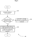
- Fig. 4 shows a flowchart of a method 400 used in a first base station, for transmitting a periodic signal to a UE according to a second embodiment of the present disclosure.
- the UE here has been in communications with a second base station. That is, the UE is a TDM UE.
- the first base station obtains a subframe configuration from the second base station.
- the subframe configuration indicates a first set of subframes assigned to communications between the UE and the first base station and a second set of subframes assigned to communications between the UE and the second base station.
- the first base station transmits the periodic signal to the UE in a first available DL subframe in the first set of subframes following the given DL subframe.
- the method 400 optionally includes a step S430.
- the first base station transmits the periodic signal to the UE in the given DL subframe.
- the periodic signal includes a periodic DL transmission scheduled via SPS.
- a periodic DL transmission scheduled via SPS will be explained in details by assuming the subframe configuration of Fig. 2 .
- a periodicity of the periodic DL transmission scheduled via SPS is 10ms.
- the set of subframes for communications between a UE and a Macro eNB and the set of subframes for communications between the UE and a pico eNB are subframe set #0 and subframe set #1 as follows:
- Such a subframe partitioning is of illustrative, and any other partitioning may be applicable to the present disclosure.
- the Macro eNB and the pico eNB may be replaced with other suitable nodes.
- Example 2 - a periodic DL transmission scheduled via SPS
- the Macro eNB transmits the periodic DL transmission scheduled via SPS to the UE in subframe 0, a next CSI will be transmitted to the Macro eNB in subframe 16 (not shown in Fig. 2 for display accuracy), instead of subframe 11 computed from Rel-11 based on the periodicity of 10ms.
- the present disclosure may delay the periodic transmission (e.g., a periodic DL transmission scheduled via SPS) to the latest valid subframe available in the subframe set of interest, thereby avoiding inconsistency between periodic transmission/reception and subframe partitioning schemes.
- periodic transmission e.g., a periodic DL transmission scheduled via SPS
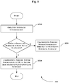
- Fig. 5 shows a flowchart of a method 500 used in a first base station for transmitting its periodic system information to a UE according to a third embodiment of the present disclosure.
- the UE here has been in communications with a second base station. That is, the UE is a TDM UE.
- the first base station obtains a subframe configuration from the second base station.
- the subframe configuration indicates a first set of subframes assigned to communications between the UE and the first base station and a second set of subframes assigned to communications between the UE and the second base station.
- the first base station transmits the periodic system information to the UE via the second base station in a DL subframe of the second set of subframes.
- the method 500 optionally includes step S530.
- the first base station transmits the periodic system information directly to the UE in the given DL subframe.
- the periodic signal may include MIB or SIB.
- Fig. 6 shows a flowchart of a method 600 used in a second base station for forwarding to a UE periodic system information of a first base station destined to the UE according to a fourth embodiment of the present disclosure.
- the UE here has been in communications with a second base station. That is, the UE is a TDM UE.
- the second base station sets a subframe configuration.
- the subframe configuration indicates a first set of subframes assigned to communications between the UE and the first base station and a second set of subframes assigned to communications between the UE and the second base station.
- the second base station informs the first base station and the UE of the subframe configuration.
- the second base station receives the periodic system information from the first base station.
- the second base station forwards, in a subframe of the second set of subframes, the periodic system information to the UE.
- the periodic system information may include MIB or SIB.
- MIBs/SIB1 of the connected node will be forwarded by the another connected node. This may avoid inconsistency between periodic transmission/reception and the subframe partitioning scheme.
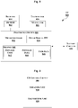
- Fig. 7 shows a sequence diagram illustrating the method (i.e., the forwarding scheme) as illustrated in Fig. 6 in details.
- the UE firstly establishes RRC connection to an eNB (e.g., a Macro eNB) by following Rel-8 ⁇ Rel-11 behaviors. This is summarized as "Setup as in Rel-8" in Fig. 7 .
- an eNB e.g., a Macro eNB
- the eNB knows that the UE wants to dual-connect to another eNB (e.g., a pico eNB), and then initiates a dual-connectivity activation, which is summarized as the "dual-connectivity setup" in Fig. 7 .
- another eNB e.g., a pico eNB
- the "dual-connectivity setup" generally includes two steps.
- the eNB sends (e.g., via PDSCH) RRCCONNECTIONRECONFIGURATION message to the UE, in which the another eNB's system information (system information originally contained in PBCH and SIBx-PDSCH) is conveyed.
- the eNB forwards the another eNB's system information to the UE.
- the UE acknowledges the reconfiguration upon safe reception by using RRCCONNECTIONRECONFIGURATIONCOMPLETE message, and starts dual-connect to the two eNBs. Then, the procedure ends.
- Fig. 8 is a block diagram of a UE 800 having been in communications with a second base station, for transmitting a periodic signal to a first base station according to the present disclosure.
- UE 800 may be configured to participate in the method illustrated in Fig. 3 , or variants thereof.
- the UE 800 includes a receiver circuit 810, which includes at least two antennas and various like radio-frequency components (not shown) and a demodulator 812.
- the receiver 810 receives radio signals received from one or more base stations and processes the signals by using known radio processing and signal processing techniques, for the processor circuits 830.
- the processing circuits 830 extract data from signals received via the receiver 810 and generate information for transmission to a corresponding eNB via the transmitter circuit 820.
- the transmitter 820 and the modulator 822 use known radio processing and signal processing components and techniques, typically according to a particular telecommunications standard such as LTE and LTE-A (Advanced), and are configured to format digital data and generate and condition a radio signal for transmission over the air.
- LTE and LTE-A Advanced
- the processing circuits 830 include one or several microprocessors 832, digital signal processors, and the like, as well as other digital hardware 834 and memory circuit 840.
- the memory 840 which includes one or several types of memory such as read-only memory (ROM), random-access memory (RAM), cache memory, flash memory devices, optical storage devices, etc., stores program code 842 for executing one or more telecommunications and/or data communications protocols and for carrying out one or more of the techniques described herein.
- the memory 840 further stores program data 844, user data 846 received from the base station and to be transmitted to the base station, and also stores various parameters, pre-determined threshold values, and/or other program data for controlling the operation of the UE 800.
- the UE 800 includes various other features that are not shown, in addition to the battery circuits 850 pictured in Fig. 8 ; these features, such as user interface circuitry, positioning circuits, and the like, are well known to those skilled in the art and are therefore not illustrated.
- processing circuits 830 using appropriate program code 842 stored in the memory 840, are configured to implement one or more of the random access techniques described herein. Of course, not all of the steps of these techniques are necessarily performed in a single microprocessor or even in a single module.
- Fig. 9 presents a more generalized view of a UE control circuit 900 configured to carry out the periodic signal transmission technique described herein.
- the UE control circuit 900 here may be also considered as a UE of the present disclosure.
- This UE control circuit 900 may have a physical configuration that corresponds directly to the processing circuits 830, for example, or may be embodied in two or more modules or units, like the configuration illustrated in Fig. 9 , and may be implemented as hardware, software or a combination of hardware and software. In any case, however, the UE control circuit 900 is configured to implement at least two functions, which are pictured in Fig. 9 as an obtaining unit 910 and a transmitting unit 920.
- the obtaining unit 910 obtains from the second base station a subframe configuration, which indicates a first set of subframes assigned to communications between the UE and the first base station and a second set of subframes assigned to communications between the UE and the second base station.
- the transmitting unit 920 is configured to, if a given UL subframe, in which the periodic signal is to be transmitted to the first base station, is not in the first set of subframes, transmit the periodic signal in a first available UL subframe in the first set of subframes following the given UL subframe.
- the transmitting unit 920 is further configured to: if the given UL subframe is in the first set of subframes, transmit the periodic signal to the first base station in the given UL subframe.
- the periodic signal may include one of:
- Fig. 10 is a block diagram of a base station 1000 for transmitting a periodic signal/its periodic system information or forwarding periodic system information of another base station to a UE having been in a connection with both of the base station 1000 and the another base station.
- the base station 1000 may be configured to implement either method as illustrated in Figs. 4-6 , or variants thereof.
- the base station 1000 includes a receiver circuit 1010, which includes at least two antennas and various other radio-frequency components (not shown) and a demodulator circuit 1012.
- the receiver 1010 receives radio signals received from one or more wireless base station and processes the signals by using known radio processing and signal processing techniques, to convert the received radio signals into digital samples for processor circuits 1030. More particularly, the receiver 1010 is capable of receiving a random access preamble from the UE by means of sits antennas.
- the processing circuits 1030 extract data from signals received via the receiver 1010 and generate information for transmission to the UE via transmitter circuit 1020.
- the transmitter 1020 and modulator 1022 use known radio processing and signal processing components and techniques, typically according to one or more telecommunications standards, and are configured to format digital data and generate and condition a radio signal, from that data, for transmission over the air.
- the processing circuits 1030 include one or several microprocessors 1032, digital signal processors, and the like, as well as other digital hardware 1034 and memory circuit 1040.
- the memory 1040 which may include one or several types of memory such as read-only memory (ROM), random-access memory (RAM), cache memory, flash memory devices, optical storage devices, etc., stores program code 1042 for executing one or more telecommunications and/or data communications protocols and for carrying out one or more of the techniques for signaling certain type of information described herein.
- Memory 1040 further stores program data 1044 as well as buffered traffic data received from UEs and from network interface 1050, and also stores various parameters, predetermined threshold values, and/or other program data for controlling the general operation of the base station 1000.
- the processing circuits 1030 using appropriate program code 1042 stored in the memory 1040, are configured to implement one or more of the techniques described herein. Of course, not all of the steps of these techniques are necessarily performed in a single microprocessor or even in a single module.
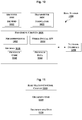
- Fig. 11 presents a more generalized view of a base station control circuit 1100 operating as a first base station.
- the base station control circuit 1100 may be configured to implement the method as illustrated in Fig. 4 .
- the base station control circuit 1100 is configured to transmit a periodic signal to a UE having been in communications with a second base station according to the present disclosure.
- This base station control circuit 1100 may have a physical configuration that corresponds directly to the processing circuits 1030, for example, or may be embodied in two or more modules or units, like the configuration illustrated in Fig. 11 , and may be implemented as hardware, software or a combination of hardware and software.
- the base station control circuit 1100 is configured to implement at least two functions, which are pictured in Fig. 11 as an obtaining unit 1110 and a transmitting unit 1120.
- the obtaining unit 1110 obtains a subframe configuration from the second base station.
- the subframe configuration indicates a first set of subframes assigned to communications between the UE and the first base station and a second set of subframes assigned to communications between the UE and the second base station.
- the transmitting unit 1120 is configured to, if a given DL subframe, in which the periodic signal is to be transmitted to the UE, is not in the first set of subframes, transmit the periodic signal to the UE in a first available DL subframe in the first set of subframes following the given DL subframe.
- the transmitting unit 1120 may be further configured to: if the given DL subframe is in the first set of subframes, transmit the periodic signal to the UE in the given DL subframe.
- the periodic signal includes a periodic DL transmission scheduled via SPS.
- Fig. 12 presents a more generalized view of a base station control circuit 1200 operating as a first base station.
- the base station control circuit 1200 may be configured to implement the method as illustrated in Fig. 5 .
- the base station control circuit 1200 is configured to transmit periodic system information of the first base station to a UE having been in communications with a second base station.
- the base station control circuit 1200 here may be also considered as a base station of the present disclosure.
- This base station control circuit 1200 may have a physical configuration that corresponds directly to the processing circuits 1030, for example, or may be embodied in two or more modules or units, like the configuration illustrated in Fig. 12 , and may be implemented as hardware, software or a combination of hardware and software. In any case, however, the base station control circuit 1200 is configured to implement at least two functions, which are pictured in Fig. 12 as an obtaining unit 1210 and a transmitting unit 1220.
- the obtaining unit 1210 obtains a subframe configuration from the second base station.
- the subframe configuration indicates a first set of subframes assigned to communications between the UE and the first base station and a second set of subframes assigned to communications between the UE and the second base station.
- the transmitting unit 1220 is configured to, if a given DL subframe, in which the periodic system information is to be transmitted to the UE, is not in the first set of subframes but in the second set of subframes, transmit the periodic system information to the UE via the second base station in a DL subframe of the second set of subframes.
- the transmitting unit 1220 may be further configured to: if the given DL subframe is in the first set of subframes, transmit the periodic system information directly to the UE in the given DL subframe.
- the periodic system information includes MIB or SIB.
- Fig. 13 presents a more generalized view of a base station control circuit 1300 operating as a second base station.
- the base station control circuit 1300 may be configured to implement the method as illustrated in Fig. 6 .
- the base station control circuit 1300 is configured to forward to a UE having been in communications with the second base station, periodic system information of a first base station destined to the UE.
- the base station control circuit 1300 here may be also considered as a base station of the present disclosure.
- This base station control circuit 1300 may have a physical configuration that corresponds directly to the processing circuits 1030, for example, or may be embodied in two or more modules or units, like the configuration illustrated in Fig. 13 , and may be implemented as hardware, software or a combination of hardware and software. In any case, however, the base station control circuit 1300 is configured to implement at least three functions, which are pictured in Fig. 13 as a setting unit 1310, an informing unit 1320, and a communicating unit 1330.
- the setting unit 1310 is configured to set a subframe configuration.
- the subframe configuration indicates a first set of subframes assigned to communications between the UE and the first base station and a second set of subframes assigned to communications between the UE and the second base station.
- the informing unit 1320 is configured to inform the first base station and the UE of the subframe configuration.
- the communicating unit 1330 is configured to receive the periodic system information from the first base station, and in a subframe of the second set of subframes, forward the periodic system information to the UE.
- the periodic system information may include MIB or SIB.
- informing unit 1320 and the communicating unit 1330 may be combined as one single unit.
Landscapes
- Engineering & Computer Science (AREA)
- Signal Processing (AREA)
- Computer Networks & Wireless Communication (AREA)
- Mobile Radio Communication Systems (AREA)
Claims (15)
- Verfahren (300), das von einer Benutzereinrichtung (UE) zum Übertragen eines periodischen Signals an eine erste Basisstation durchgeführt wird, wobei die UE in Kommunikation mit einer zweiten Basisstation stand, wobei ein auf einem Zeitmultiplexverfahren, TDM, basierendes Dual-Anschlusssystem verwendet wird, gekennzeichnet durch:Erhalten (S310) einer Unterrahmenkonfiguration von der zweiten Basisstation, die einen ersten Satz von Unterrahmen angibt, die der Kommunikation zwischen der UE und der ersten Basisstation zugeordnet sind, und einen zweiten Satz von Unterrahmen, die der Kommunikation zwischen der UE und der zweiten Basisstation zugeordnet sind; undwenn sich ein bestimmter Uplink-Unterrahmen, in dem das periodische Signal an die erste Basisstation übertragen werden soll, nicht im ersten Satz von Unterrahmen befindet, Übertragen (S320) des periodischen Signals in einem ersten verfügbaren Uplink-Unterrahmen im ersten Satz von Unterrahmen nach dem bestimmten Uplink-Unterrahmen.
- Verfahren nach Anspruch 1, ferner umfassend:
wenn sich der bestimmte Uplink-Unterrahmen im ersten Satz von Unterrahmen befindet, Übertragen (S330) des periodischen Signals an die erste Basisstation in dem bestimmten Uplink-Unterrahmen. - Verfahren nach Anspruch 1 oder 2, wobei das periodische Signal eines von Folgendem einschließt:eine periodische Kanalzustandsmeldung unter Verwendung des physischen Uplink-Steuerkanals, PUCCH;ein periodisches Sounding Reference Signal, SRS; odereine periodische Uplink-Übertragung, die über semipersistente Planung, SPS, geplant ist.
- Verfahren (400), das von einer ersten Basisstation zum Übertragen eines periodischen Signals an eine Benutzereinrichtung, UE, durchgeführt wird, wobei die UE in Kommunikation mit einer zweiten Basisstation stand, wobei ein auf TDM basierendes Dual-Anschlusssystem verwendet wird, gekennzeichnet durch:Erhalten (S410) einer Unterrahmenkonfiguration von der zweiten Basisstation, die einen ersten Satz von Unterrahmen angibt, die der Kommunikation zwischen der UE und der ersten Basisstation zugeordnet sind, und einen zweiten Satz von Unterrahmen, die der Kommunikation zwischen der UE und der zweiten Basisstation zugeordnet sind; undwenn sich ein bestimmter Downlink-Unterrahmen, in dem das periodische Signal an die UE übertragen werden soll, nicht im ersten Satz von Unterrahmen befindet, Übertragen (S420) des periodischen Signals an die UE in einem ersten verfügbaren Downlink-Unterrahmen im ersten Satz von Unterrahmen nach dem bestimmten Downlink-Unterrahmen.
- Verfahren nach Anspruch 4, ferner umfassend:
wenn sich der bestimmte Downlink-Unterrahmen im ersten Satz von Unterrahmen befindet, Übertragen (S430) des periodischen Signals an die UE in dem bestimmten Downlink-Unterrahmen. - Verfahren nach Anspruch 4 oder 5, wobei das periodische Signal eine periodische Downlink-Übertragung einschließt, die über semipersistente Planung, SPS, geplant ist.
- Verfahren (500), das von einer ersten Basisstation zum Übertragen ihrer periodischen Systeminformation an eine Benutzereinrichtung, UE, durchgeführt wird, wobei die UE in Kommunikation mit einer zweiten Basisstation stand, wobei ein auf TDM basierendes Dual-Anschlusssystem verwendet wird, gekennzeichnet durch:Erhalten (S510) einer Unterrahmenkonfiguration von der zweiten Basisstation, die einen ersten Satz von Unterrahmen angibt, die der Kommunikation zwischen der UE und der ersten Basisstation zugeordnet sind, und einen zweiten Satz von Unterrahmen, die der Kommunikation zwischen der UE und der zweiten Basisstation zugeordnet sind; undwenn sich ein bestimmter Downlink-Unterrahmen, in dem die periodische Systeminformation an die UE übertragen werden soll, nicht im ersten Satz von Unterrahmen, sondern im zweiten Satz von Unterrahmen befindet, Übertragen (S520) der periodischen Systeminformation an die UE über die zweite Basisstation in einem Downlink-Unterrahmen des zweiten Satzes von Unterrahmen.
- Verfahren nach Anspruch 7, ferner umfassend:
wenn sich der bestimmte Downlink-Unterrahmen im ersten Satz von Unterrahmen befindet, Übertragen (S530) der periodischen Systeminformation direkt an die UE in dem bestimmten Downlink-Unterrahmen. - Verfahren nach Anspruch 7 oder 8, wobei die periodische Systeminformation Folgendes einschließt:Hauptinformationsblock, MIB; oderSekundärer Informationsblock, SIB.
- Verfahren (600), das von einer zweiten Basisstation durchgeführt wird, um an eine Benutzereinrichtung (UE) periodische Systeminformationen einer ersten Basisstation, die für die UE bestimmt sind, weiterzuleiten, wobei die UE in Kommunikation mit der zweiten Basisstation stand, wobei ein auf TDM basierendes Dual-Anschlusssystem verwendet wird, gekennzeichnet durch:Einstellen (S610) einer Unterrahmenkonfiguration, die einen ersten Satz von Unterrahmen angibt, die der Kommunikation zwischen der UE und der ersten Basisstation zugeordnet sind, und einen zweiten Satz von Unterrahmen, die der Kommunikation zwischen der UE und der zweiten Basisstation zugeordnet sind;Informieren (S620) der ersten Basisstation und der UE über die Unterrahmenkonfiguration;Empfangen der periodischen Systeminformation von der ersten Basisstation (S630); undin einem Unterrahmen des zweiten Satzes von Unterrahmen, Weiterleiten der periodischen Systeminformation an die UE (S640).
- Verfahren nach Anspruch 10, wobei die periodische Systeminformation Folgendes einschließt:Hauptinformationsblock, MIB; oderSekundärer Informationsblock, SIB.
- Benutzereinrichtung, UE, (900) zum Übertragen eines periodischen Signals an eine erste Basisstation, wobei die UE in Kommunikation mit einer zweiten Basisstation stand, wobei ein auf TDM basierendes Dual-Anschlusssystem verwendet wird, dadurch gekennzeichnet, dass die UE Folgendes umfasst:eine Erhaltungseinheit (910), die konfiguriert ist, um von der zweiten Basisstation eine Unterrahmenkonfiguration zu erhalten, die einen ersten Satz von Unterrahmen angibt, die der Kommunikation zwischen der UE und der ersten Basisstation zugeordnet sind, und einen zweiten Satz von Unterrahmen, die der Kommunikation zwischen der UE und der zweiten Basisstation zugeordnet sind; undeine Sendeeinheit (920), die so konfiguriert ist, dass sie, wenn sich ein bestimmter Uplink-Unterrahmen, in dem das periodische Signal an die erste Basisstation übertragen werden soll, nicht im ersten Satz von Unterrahmen befindet, das periodische Signal in einem ersten verfügbaren Uplink-Unterrahmen im ersten Satz von Unterrahmen nach dem bestimmten Uplink-Unterrahmen überträgt.
- Erste Basisstation (1100) zum Übertragen eines periodischen Signals an eine Benutzereinrichtung (UE), wobei die UE in Kommunikation mit einer zweiten Basisstation stand, wobei ein auf TDM basierendes Dual-Anschlusssystem verwendet wird, dadurch gekennzeichnet, dass die erste Basisstation Folgendes umfasst:eine Erhaltungseinheit (1110), die konfiguriert ist, um von der zweiten Basisstation eine Unterrahmenkonfiguration zu erhalten, die einen ersten Satz von Unterrahmen anzeigt, die der Kommunikation zwischen der UE und der ersten Basisstation zugeordnet sind, und einen zweiten Satz von Unterrahmen, die der Kommunikation zwischen der UE und der zweiten Basisstation zugeordnet sind; undeine Sendeeinheit (1120), die so konfiguriert ist, dass sie, wenn sich ein bestimmter Downlink-Unterrahmen, in dem das periodische Signal an die UE übertragen werden soll, nicht im ersten Satz von Unterrahmen befindet, das periodische Signal an die UE in einem ersten verfügbaren Downlink-Unterrahmen im ersten Satz von Unterrahmen nach dem bestimmten Downlink-Unterrahmen überträgt.
- Erste Basisstation (1200) zum Übertragen ihrer periodischen Systeminformation an eine Benutzereinrichtung, UE, wobei die UE in Kommunikation mit einer zweiten Basisstation stand, wobei ein auf TDM basierendes Dual-Anschlusssystem verwendet wird, dadurch gekennzeichnet, dass die erste Basisstation Folgendes umfasst:eine Erhaltungseinheit (1210), die konfiguriert ist, um von der zweiten Basisstation eine Unterrahmenkonfiguration zu erhalten, die einen ersten Satz von Unterrahmen anzeigt, die der Kommunikation zwischen der UE und der ersten Basisstation zugeordnet sind, und einen zweiten Satz von Unterrahmen, die der Kommunikation zwischen der UE und der zweiten Basisstation zugeordnet sind; undeine Sendeeinheit (1220), die so konfiguriert ist, dass sie, wenn sich ein bestimmter Downlink-Unterrahmen, in dem die periodische Systeminformation an die UE übertragen werden soll, nicht im ersten Satz von Unterrahmen, sondern im zweiten Satz von Unterrahmen befindet, die periodische Systeminformation an die UE über die zweite Basisstation in einem Downlink-Unterrahmen des zweiten Satzes von Unterrahmen überträgt.
- Zweite Basisstation (1300) zum Weiterleiten an eine Benutzereinrichtung, UE, periodischer Systeminformationen einer ersten Basisstation, die für die UE bestimmt sind, wobei die UE in Kommunikation mit der zweiten Basisstation stand, wobei ein auf TDM basierendes Dual-Anschlusssystem verwendet wird, dadurch gekennzeichnet, dass die zweite Basisstation Folgendes umfasst:eine Einstelleinheit (1310), die konfiguriert ist, um eine Unterrahmenkonfiguration zu setzen, die einen ersten Satz von Unterrahmen anzeigt, die der Kommunikation zwischen der UE und der ersten Basisstation zugeordnet sind, und einen zweiten Satz von Unterrahmen, die der Kommunikation zwischen der UE und der zweiten Basisstation zugeordnet sind;eine Informationseinheit (1320), die konfiguriert ist, um die erste Basisstation und die UE über die Unterrahmenkonfiguration zu informieren; undeine Kommunikationseinheit (1330), die konfiguriert ist, um die periodischen Systeminformationen von der ersten Basisstation zu empfangen, und um in einem Unterrahmen des zweiten Satzes von Unterrahmen die periodische Systeminformation an die UE weiterzuleiten.
Applications Claiming Priority (1)
| Application Number | Priority Date | Filing Date | Title |
|---|---|---|---|
| PCT/CN2013/074357 WO2014169459A1 (en) | 2013-04-18 | 2013-04-18 | Method, ue and base station for transmitting periodic signal/periodic system information, and method and base station for forwarding periodic system information |
Publications (3)
| Publication Number | Publication Date |
|---|---|
| EP2987355A1 EP2987355A1 (de) | 2016-02-24 |
| EP2987355A4 EP2987355A4 (de) | 2016-12-07 |
| EP2987355B1 true EP2987355B1 (de) | 2019-01-16 |
Family
ID=51730696
Family Applications (1)
| Application Number | Title | Priority Date | Filing Date |
|---|---|---|---|
| EP13882071.7A Active EP2987355B1 (de) | 2013-04-18 | 2013-04-18 | Verfahren, benutzervorrichtung und basisstation zur übertragung eines periodischen signals/periodischer systeminformationen sowie verfahren und basisstation zur weiterleitung von periodischen systeminformationen |
Country Status (4)
| Country | Link |
|---|---|
| US (1) | US9974061B2 (de) |
| EP (1) | EP2987355B1 (de) |
| CN (1) | CN105122885B (de) |
| WO (1) | WO2014169459A1 (de) |
Families Citing this family (9)
| Publication number | Priority date | Publication date | Assignee | Title |
|---|---|---|---|---|
| US10390271B2 (en) * | 2013-05-20 | 2019-08-20 | Nokia Technologies Oy | Indication of TDM extension pattern for dual connectivity |
| WO2015020605A1 (en) * | 2013-08-09 | 2015-02-12 | Telefonaktiebolaget L M Ericsson (Publ) | Resource allocation for mobile terminal configured for dual connectivity |
| US9913255B2 (en) | 2014-01-28 | 2018-03-06 | Mediatek Singapore Pte. Ltd. | Time domain multiplexing UL transmission on multiple serving cells for a mobile station with single transmitter |
| WO2017135677A1 (en) * | 2016-02-03 | 2017-08-10 | Lg Electronics Inc. | Method and apparatus for performing user equipment triggered semi-persistent scheduling activation in wireless communication system |
| CN107734628B (zh) * | 2016-08-10 | 2019-12-20 | 电信科学技术研究院 | 一种通信系统中的信息处理方法及装置 |
| US10485048B2 (en) * | 2017-06-15 | 2019-11-19 | Apple Inc. | TDM transmission for inter-RAT dual connectivity UE |
| US10972950B2 (en) * | 2018-07-20 | 2021-04-06 | Qualcomm Incorporated | Methods and apparatus for handover enhancements |
| CN110213832B (zh) * | 2019-05-29 | 2022-05-24 | 成都中科微信息技术研究院有限公司 | 一种结合pucch周期的调度基站及系统 |
| CN110225596B (zh) * | 2019-05-29 | 2022-05-24 | 成都中科微信息技术研究院有限公司 | 一种结合pucch周期的调度方法及系统 |
Family Cites Families (11)
| Publication number | Priority date | Publication date | Assignee | Title |
|---|---|---|---|---|
| CN102187727B (zh) * | 2009-03-12 | 2015-03-25 | Lg电子株式会社 | 无线通信系统中在用户设备处切换操作载波的方法 |
| US9673952B2 (en) * | 2009-04-10 | 2017-06-06 | Qualcomm Inc. | Method and apparatus for supporting user equipments on different system bandwidths |
| CN101925110B (zh) | 2009-06-16 | 2013-08-07 | 中兴通讯股份有限公司 | 中继链路上行反馈信息的传输方法、中继站及基站 |
| US9184899B2 (en) * | 2009-10-14 | 2015-11-10 | Qualcomm Incorporated | Downlink association set for uplink ACK/NACK in time division duplex system |
| CN102724688B (zh) * | 2011-03-30 | 2017-04-05 | 华为技术有限公司 | 测量载波的方法和装置 |
| US9320062B2 (en) * | 2012-04-17 | 2016-04-19 | Qualcomm Incorporated | Communication in a heterogeneous network with carrier aggregation |
| US9014064B2 (en) * | 2012-05-11 | 2015-04-21 | Intel Corporation | Scheduling and hybrid automatic repeat request (HARQ) timing indication for an uplink-downlink (UL-DL) reconfiguration |
| US9497747B2 (en) * | 2012-06-22 | 2016-11-15 | Qualcomm Incorporated | Data transmission in carrier aggregation with different carrier configurations |
| US9264997B2 (en) * | 2012-07-03 | 2016-02-16 | Qualcomm Incorporated | Apparatus and methods of energy efficient communication |
| EP3883170B1 (de) * | 2012-09-28 | 2022-11-30 | BlackBerry Limited | Verfahren und vorrichtung zur ermöglichung von verbesserungen an flexiblen unterrahmen in heterogenen lte-netzwerken |
| US9509483B2 (en) * | 2012-11-12 | 2016-11-29 | Qualcomm Incorporated | Uplink control and data transmission in multiflow-enabled networks |
-
2013
- 2013-04-18 WO PCT/CN2013/074357 patent/WO2014169459A1/en active Application Filing
- 2013-04-18 US US14/783,631 patent/US9974061B2/en active Active
- 2013-04-18 EP EP13882071.7A patent/EP2987355B1/de active Active
- 2013-04-18 CN CN201380075698.7A patent/CN105122885B/zh not_active Expired - Fee Related
Non-Patent Citations (1)
| Title |
|---|
| None * |
Also Published As
| Publication number | Publication date |
|---|---|
| US20160088609A1 (en) | 2016-03-24 |
| US9974061B2 (en) | 2018-05-15 |
| WO2014169459A1 (en) | 2014-10-23 |
| CN105122885B (zh) | 2019-04-26 |
| CN105122885A (zh) | 2015-12-02 |
| EP2987355A4 (de) | 2016-12-07 |
| EP2987355A1 (de) | 2016-02-24 |
Similar Documents
| Publication | Publication Date | Title |
|---|---|---|
| US11006427B2 (en) | Communication system, base station, and communication terminal for controlling interference from neighboring cells | |
| EP2987355B1 (de) | Verfahren, benutzervorrichtung und basisstation zur übertragung eines periodischen signals/periodischer systeminformationen sowie verfahren und basisstation zur weiterleitung von periodischen systeminformationen | |
| KR102103725B1 (ko) | 무선 통신 시스템에서 자원을 선택하고 pssch를 전송하는 방법 및 장치 | |
| US10165565B2 (en) | Legacy and new radio coexistence frame and control design | |
| EP3582578B1 (de) | Verfahren, durch das ein d2d-endgerät eine kommunikationsverbindung mit einer kommunikationsvorrichtung in einem drahtloskommunikationssystem bildet, und vorrichtung dafür | |
| US11985557B2 (en) | Signaling for conditional primary secondary cell addition/change configuration | |
| CN106537964B (zh) | 用于网络适配和利用下行链路发现参考信号的设备、网络和方法 | |
| US9794033B2 (en) | Systems, methods and devices for opportunistic networking | |
| US20170295589A1 (en) | Fifth generation (5g) time division duplex (tdd) legacy coexistence design | |
| US11716775B2 (en) | Soft physical cell identifier (PCI) change | |
| KR20160114066A (ko) | 무선 통신 시스템에서 장치 대 장치 단말의 신호 송수신 방법 및 장치 | |
| EP3566367B1 (de) | Verfahren, vorrichtung und knoten zur anpassung einer numerologie in abhängigkeit von einer position einer drahtlosen vorrichtung | |
| US11937135B2 (en) | Signaling of delta configuration for handover | |
| US11963232B2 (en) | Beam refinement using channel state information reference signal in random access procedure | |
| US11997726B2 (en) | Beam-specific coverage enhancement for random access procedure | |
| CN114982309B (zh) | 用于非陆地网络的定时调整 | |
| JP2020517205A (ja) | 無線通信システムにおいてサイドリンク信号を送信する方法及び装置 | |
| CN113396627A (zh) | 针对背对背授权和多传输时间间隔(多tti)授权发信号通知先听后说(lbt)类型和间隙 | |
| CN114026930A (zh) | 用于平衡功率节省和公共警报系统监视的寻呼技术 | |
| JP2020522172A (ja) | 無線通信システムにおいて端末が送信ブロックに対する送信リソースを選択する方法及びそのための装置 | |
| EP3504904B1 (de) | Physikalischer zellidentifikationskanal (pcich) | |
| CN112673684A (zh) | 通信系统、通信终端及基站 | |
| WO2023158897A1 (en) | Cell selection and re-selection procedures for reduced capability user equipment | |
| EP4158926A1 (de) | Fähigkeitsinformationen für ein benutzergerät | |
| CN118139186A (zh) | 通信系统、基站和通信终端 |
Legal Events
| Date | Code | Title | Description |
|---|---|---|---|
| PUAI | Public reference made under article 153(3) epc to a published international application that has entered the european phase |
Free format text: ORIGINAL CODE: 0009012 |
|
| 17P | Request for examination filed |
Effective date: 20151013 |
|
| AK | Designated contracting states |
Kind code of ref document: A1 Designated state(s): AL AT BE BG CH CY CZ DE DK EE ES FI FR GB GR HR HU IE IS IT LI LT LU LV MC MK MT NL NO PL PT RO RS SE SI SK SM TR |
|
| AX | Request for extension of the european patent |
Extension state: BA ME |
|
| DAX | Request for extension of the european patent (deleted) | ||
| A4 | Supplementary search report drawn up and despatched |
Effective date: 20161107 |
|
| RIC1 | Information provided on ipc code assigned before grant |
Ipc: H04W 76/02 20090101AFI20161031BHEP Ipc: H04L 5/00 20060101ALN20161031BHEP Ipc: H04W 16/10 20090101ALN20161031BHEP Ipc: H04W 84/04 20090101ALN20161031BHEP |
|
| REG | Reference to a national code |
Ref country code: DE Ref legal event code: R079 Ref document number: 602013050073 Country of ref document: DE Free format text: PREVIOUS MAIN CLASS: H04W0036040000 Ipc: H04W0072040000 |
|
| GRAP | Despatch of communication of intention to grant a patent |
Free format text: ORIGINAL CODE: EPIDOSNIGR1 |
|
| STAA | Information on the status of an ep patent application or granted ep patent |
Free format text: STATUS: GRANT OF PATENT IS INTENDED |
|
| RIC1 | Information provided on ipc code assigned before grant |
Ipc: H04W 84/04 20090101ALN20181029BHEP Ipc: H04L 5/00 20060101ALI20181029BHEP Ipc: H04W 76/15 20160224ALN20181029BHEP Ipc: H04W 72/04 20090101AFI20181029BHEP |
|
| GRAS | Grant fee paid |
Free format text: ORIGINAL CODE: EPIDOSNIGR3 |
|
| RIC1 | Information provided on ipc code assigned before grant |
Ipc: H04W 72/04 20090101AFI20181106BHEP Ipc: H04W 76/15 20160224ALN20181106BHEP Ipc: H04L 5/00 20060101ALI20181106BHEP Ipc: H04W 84/04 20090101ALN20181106BHEP |
|
| GRAA | (expected) grant |
Free format text: ORIGINAL CODE: 0009210 |
|
| STAA | Information on the status of an ep patent application or granted ep patent |
Free format text: STATUS: THE PATENT HAS BEEN GRANTED |
|
| INTG | Intention to grant announced |
Effective date: 20181119 |
|
| RIC1 | Information provided on ipc code assigned before grant |
Ipc: H04W 76/15 20180101ALN20181106BHEP Ipc: H04W 84/04 20090101ALN20181106BHEP Ipc: H04L 5/00 20060101ALI20181106BHEP Ipc: H04W 72/04 20090101AFI20181106BHEP |
|
| AK | Designated contracting states |
Kind code of ref document: B1 Designated state(s): AL AT BE BG CH CY CZ DE DK EE ES FI FR GB GR HR HU IE IS IT LI LT LU LV MC MK MT NL NO PL PT RO RS SE SI SK SM TR |
|
| REG | Reference to a national code |
Ref country code: GB Ref legal event code: FG4D |
|
| REG | Reference to a national code |
Ref country code: CH Ref legal event code: EP Ref country code: CH Ref legal event code: PK Free format text: BERICHTIGUNGEN |
|
| REG | Reference to a national code |
Ref country code: IE Ref legal event code: FG4D |
|
| RIC2 | Information provided on ipc code assigned after grant |
Ipc: H04W 76/15 20180101ALN20181106BHEP Ipc: H04W 72/04 20090101AFI20181106BHEP Ipc: H04L 5/00 20060101ALI20181106BHEP Ipc: H04W 84/04 20090101ALN20181106BHEP |
|
| REG | Reference to a national code |
Ref country code: AT Ref legal event code: REF Ref document number: 1090707 Country of ref document: AT Kind code of ref document: T Effective date: 20190215 |
|
| REG | Reference to a national code |
Ref country code: DE Ref legal event code: R096 Ref document number: 602013050073 Country of ref document: DE |
|
| REG | Reference to a national code |
Ref country code: NL Ref legal event code: MP Effective date: 20190116 |
|
| REG | Reference to a national code |
Ref country code: LT Ref legal event code: MG4D |
|
| PG25 | Lapsed in a contracting state [announced via postgrant information from national office to epo] |
Ref country code: NL Free format text: LAPSE BECAUSE OF FAILURE TO SUBMIT A TRANSLATION OF THE DESCRIPTION OR TO PAY THE FEE WITHIN THE PRESCRIBED TIME-LIMIT Effective date: 20190116 |
|
| REG | Reference to a national code |
Ref country code: AT Ref legal event code: MK05 Ref document number: 1090707 Country of ref document: AT Kind code of ref document: T Effective date: 20190116 |
|
| PG25 | Lapsed in a contracting state [announced via postgrant information from national office to epo] |
Ref country code: SE Free format text: LAPSE BECAUSE OF FAILURE TO SUBMIT A TRANSLATION OF THE DESCRIPTION OR TO PAY THE FEE WITHIN THE PRESCRIBED TIME-LIMIT Effective date: 20190116 Ref country code: ES Free format text: LAPSE BECAUSE OF FAILURE TO SUBMIT A TRANSLATION OF THE DESCRIPTION OR TO PAY THE FEE WITHIN THE PRESCRIBED TIME-LIMIT Effective date: 20190116 Ref country code: LT Free format text: LAPSE BECAUSE OF FAILURE TO SUBMIT A TRANSLATION OF THE DESCRIPTION OR TO PAY THE FEE WITHIN THE PRESCRIBED TIME-LIMIT Effective date: 20190116 Ref country code: FI Free format text: LAPSE BECAUSE OF FAILURE TO SUBMIT A TRANSLATION OF THE DESCRIPTION OR TO PAY THE FEE WITHIN THE PRESCRIBED TIME-LIMIT Effective date: 20190116 Ref country code: PL Free format text: LAPSE BECAUSE OF FAILURE TO SUBMIT A TRANSLATION OF THE DESCRIPTION OR TO PAY THE FEE WITHIN THE PRESCRIBED TIME-LIMIT Effective date: 20190116 Ref country code: NO Free format text: LAPSE BECAUSE OF FAILURE TO SUBMIT A TRANSLATION OF THE DESCRIPTION OR TO PAY THE FEE WITHIN THE PRESCRIBED TIME-LIMIT Effective date: 20190416 Ref country code: PT Free format text: LAPSE BECAUSE OF FAILURE TO SUBMIT A TRANSLATION OF THE DESCRIPTION OR TO PAY THE FEE WITHIN THE PRESCRIBED TIME-LIMIT Effective date: 20190516 |
|
| PG25 | Lapsed in a contracting state [announced via postgrant information from national office to epo] |
Ref country code: IS Free format text: LAPSE BECAUSE OF FAILURE TO SUBMIT A TRANSLATION OF THE DESCRIPTION OR TO PAY THE FEE WITHIN THE PRESCRIBED TIME-LIMIT Effective date: 20190516 Ref country code: BG Free format text: LAPSE BECAUSE OF FAILURE TO SUBMIT A TRANSLATION OF THE DESCRIPTION OR TO PAY THE FEE WITHIN THE PRESCRIBED TIME-LIMIT Effective date: 20190416 Ref country code: HR Free format text: LAPSE BECAUSE OF FAILURE TO SUBMIT A TRANSLATION OF THE DESCRIPTION OR TO PAY THE FEE WITHIN THE PRESCRIBED TIME-LIMIT Effective date: 20190116 Ref country code: LV Free format text: LAPSE BECAUSE OF FAILURE TO SUBMIT A TRANSLATION OF THE DESCRIPTION OR TO PAY THE FEE WITHIN THE PRESCRIBED TIME-LIMIT Effective date: 20190116 Ref country code: GR Free format text: LAPSE BECAUSE OF FAILURE TO SUBMIT A TRANSLATION OF THE DESCRIPTION OR TO PAY THE FEE WITHIN THE PRESCRIBED TIME-LIMIT Effective date: 20190417 Ref country code: RS Free format text: LAPSE BECAUSE OF FAILURE TO SUBMIT A TRANSLATION OF THE DESCRIPTION OR TO PAY THE FEE WITHIN THE PRESCRIBED TIME-LIMIT Effective date: 20190116 |
|
| REG | Reference to a national code |
Ref country code: DE Ref legal event code: R097 Ref document number: 602013050073 Country of ref document: DE |
|
| PG25 | Lapsed in a contracting state [announced via postgrant information from national office to epo] |
Ref country code: RO Free format text: LAPSE BECAUSE OF FAILURE TO SUBMIT A TRANSLATION OF THE DESCRIPTION OR TO PAY THE FEE WITHIN THE PRESCRIBED TIME-LIMIT Effective date: 20190116 Ref country code: CZ Free format text: LAPSE BECAUSE OF FAILURE TO SUBMIT A TRANSLATION OF THE DESCRIPTION OR TO PAY THE FEE WITHIN THE PRESCRIBED TIME-LIMIT Effective date: 20190116 Ref country code: EE Free format text: LAPSE BECAUSE OF FAILURE TO SUBMIT A TRANSLATION OF THE DESCRIPTION OR TO PAY THE FEE WITHIN THE PRESCRIBED TIME-LIMIT Effective date: 20190116 Ref country code: AT Free format text: LAPSE BECAUSE OF FAILURE TO SUBMIT A TRANSLATION OF THE DESCRIPTION OR TO PAY THE FEE WITHIN THE PRESCRIBED TIME-LIMIT Effective date: 20190116 Ref country code: SK Free format text: LAPSE BECAUSE OF FAILURE TO SUBMIT A TRANSLATION OF THE DESCRIPTION OR TO PAY THE FEE WITHIN THE PRESCRIBED TIME-LIMIT Effective date: 20190116 Ref country code: IT Free format text: LAPSE BECAUSE OF FAILURE TO SUBMIT A TRANSLATION OF THE DESCRIPTION OR TO PAY THE FEE WITHIN THE PRESCRIBED TIME-LIMIT Effective date: 20190116 Ref country code: AL Free format text: LAPSE BECAUSE OF FAILURE TO SUBMIT A TRANSLATION OF THE DESCRIPTION OR TO PAY THE FEE WITHIN THE PRESCRIBED TIME-LIMIT Effective date: 20190116 Ref country code: DK Free format text: LAPSE BECAUSE OF FAILURE TO SUBMIT A TRANSLATION OF THE DESCRIPTION OR TO PAY THE FEE WITHIN THE PRESCRIBED TIME-LIMIT Effective date: 20190116 |
|
| PLBE | No opposition filed within time limit |
Free format text: ORIGINAL CODE: 0009261 |
|
| STAA | Information on the status of an ep patent application or granted ep patent |
Free format text: STATUS: NO OPPOSITION FILED WITHIN TIME LIMIT |
|
| PG25 | Lapsed in a contracting state [announced via postgrant information from national office to epo] |
Ref country code: SM Free format text: LAPSE BECAUSE OF FAILURE TO SUBMIT A TRANSLATION OF THE DESCRIPTION OR TO PAY THE FEE WITHIN THE PRESCRIBED TIME-LIMIT Effective date: 20190116 |
|
| REG | Reference to a national code |
Ref country code: CH Ref legal event code: PL |
|
| REG | Reference to a national code |
Ref country code: BE Ref legal event code: MM Effective date: 20190430 |
|
| 26N | No opposition filed |
Effective date: 20191017 |
|
| PG25 | Lapsed in a contracting state [announced via postgrant information from national office to epo] |
Ref country code: LU Free format text: LAPSE BECAUSE OF NON-PAYMENT OF DUE FEES Effective date: 20190418 Ref country code: MC Free format text: LAPSE BECAUSE OF FAILURE TO SUBMIT A TRANSLATION OF THE DESCRIPTION OR TO PAY THE FEE WITHIN THE PRESCRIBED TIME-LIMIT Effective date: 20190116 |
|
| PG25 | Lapsed in a contracting state [announced via postgrant information from national office to epo] |
Ref country code: CH Free format text: LAPSE BECAUSE OF NON-PAYMENT OF DUE FEES Effective date: 20190430 Ref country code: LI Free format text: LAPSE BECAUSE OF NON-PAYMENT OF DUE FEES Effective date: 20190430 |
|
| PG25 | Lapsed in a contracting state [announced via postgrant information from national office to epo] |
Ref country code: BE Free format text: LAPSE BECAUSE OF NON-PAYMENT OF DUE FEES Effective date: 20190430 Ref country code: SI Free format text: LAPSE BECAUSE OF FAILURE TO SUBMIT A TRANSLATION OF THE DESCRIPTION OR TO PAY THE FEE WITHIN THE PRESCRIBED TIME-LIMIT Effective date: 20190116 |
|
| PG25 | Lapsed in a contracting state [announced via postgrant information from national office to epo] |
Ref country code: TR Free format text: LAPSE BECAUSE OF FAILURE TO SUBMIT A TRANSLATION OF THE DESCRIPTION OR TO PAY THE FEE WITHIN THE PRESCRIBED TIME-LIMIT Effective date: 20190116 |
|
| PG25 | Lapsed in a contracting state [announced via postgrant information from national office to epo] |
Ref country code: IE Free format text: LAPSE BECAUSE OF NON-PAYMENT OF DUE FEES Effective date: 20190418 |
|
| PG25 | Lapsed in a contracting state [announced via postgrant information from national office to epo] |
Ref country code: CY Free format text: LAPSE BECAUSE OF FAILURE TO SUBMIT A TRANSLATION OF THE DESCRIPTION OR TO PAY THE FEE WITHIN THE PRESCRIBED TIME-LIMIT Effective date: 20190116 |
|
| PG25 | Lapsed in a contracting state [announced via postgrant information from national office to epo] |
Ref country code: MT Free format text: LAPSE BECAUSE OF FAILURE TO SUBMIT A TRANSLATION OF THE DESCRIPTION OR TO PAY THE FEE WITHIN THE PRESCRIBED TIME-LIMIT Effective date: 20190116 Ref country code: HU Free format text: LAPSE BECAUSE OF FAILURE TO SUBMIT A TRANSLATION OF THE DESCRIPTION OR TO PAY THE FEE WITHIN THE PRESCRIBED TIME-LIMIT; INVALID AB INITIO Effective date: 20130418 |
|
| PG25 | Lapsed in a contracting state [announced via postgrant information from national office to epo] |
Ref country code: MK Free format text: LAPSE BECAUSE OF FAILURE TO SUBMIT A TRANSLATION OF THE DESCRIPTION OR TO PAY THE FEE WITHIN THE PRESCRIBED TIME-LIMIT Effective date: 20190116 |
|
| PGFP | Annual fee paid to national office [announced via postgrant information from national office to epo] |
Ref country code: GB Payment date: 20220427 Year of fee payment: 10 Ref country code: DE Payment date: 20220427 Year of fee payment: 10 |
|
| PGFP | Annual fee paid to national office [announced via postgrant information from national office to epo] |
Ref country code: FR Payment date: 20230425 Year of fee payment: 11 |
|
| REG | Reference to a national code |
Ref country code: DE Ref legal event code: R119 Ref document number: 602013050073 Country of ref document: DE |
|
| GBPC | Gb: european patent ceased through non-payment of renewal fee |
Effective date: 20230418 |
|
| PG25 | Lapsed in a contracting state [announced via postgrant information from national office to epo] |
Ref country code: GB Free format text: LAPSE BECAUSE OF NON-PAYMENT OF DUE FEES Effective date: 20230418 |
|
| PG25 | Lapsed in a contracting state [announced via postgrant information from national office to epo] |
Ref country code: GB Free format text: LAPSE BECAUSE OF NON-PAYMENT OF DUE FEES Effective date: 20230418 Ref country code: DE Free format text: LAPSE BECAUSE OF NON-PAYMENT OF DUE FEES Effective date: 20231103 |