EP2987291B1 - System and method for communicating with shaped cyclic time-domain waveforms - Google Patents
System and method for communicating with shaped cyclic time-domain waveforms Download PDFInfo
- Publication number
- EP2987291B1 EP2987291B1 EP14725319.9A EP14725319A EP2987291B1 EP 2987291 B1 EP2987291 B1 EP 2987291B1 EP 14725319 A EP14725319 A EP 14725319A EP 2987291 B1 EP2987291 B1 EP 2987291B1
- Authority
- EP
- European Patent Office
- Prior art keywords
- symbol vector
- transform
- vector
- domain
- generate
- Prior art date
- Legal status (The legal status is an assumption and is not a legal conclusion. Google has not performed a legal analysis and makes no representation as to the accuracy of the status listed.)
- Active
Links
Images


Classifications
-
- H—ELECTRICITY
- H04—ELECTRIC COMMUNICATION TECHNIQUE
- H04L—TRANSMISSION OF DIGITAL INFORMATION, e.g. TELEGRAPHIC COMMUNICATION
- H04L5/00—Arrangements affording multiple use of the transmission path
- H04L5/0001—Arrangements for dividing the transmission path
- H04L5/0003—Two-dimensional division
- H04L5/0005—Time-frequency
-
- H—ELECTRICITY
- H04—ELECTRIC COMMUNICATION TECHNIQUE
- H04L—TRANSMISSION OF DIGITAL INFORMATION, e.g. TELEGRAPHIC COMMUNICATION
- H04L27/00—Modulated-carrier systems
- H04L27/32—Carrier systems characterised by combinations of two or more of the types covered by groups H04L27/02, H04L27/10, H04L27/18 or H04L27/26
- H04L27/34—Amplitude- and phase-modulated carrier systems, e.g. quadrature-amplitude modulated carrier systems
- H04L27/36—Modulator circuits; Transmitter circuits
-
- H—ELECTRICITY
- H04—ELECTRIC COMMUNICATION TECHNIQUE
- H04L—TRANSMISSION OF DIGITAL INFORMATION, e.g. TELEGRAPHIC COMMUNICATION
- H04L25/00—Baseband systems
- H04L25/02—Details ; arrangements for supplying electrical power along data transmission lines
- H04L25/03—Shaping networks in transmitter or receiver, e.g. adaptive shaping networks
- H04L25/03828—Arrangements for spectral shaping; Arrangements for providing signals with specified spectral properties
- H04L25/03834—Arrangements for spectral shaping; Arrangements for providing signals with specified spectral properties using pulse shaping
-
- H—ELECTRICITY
- H04—ELECTRIC COMMUNICATION TECHNIQUE
- H04L—TRANSMISSION OF DIGITAL INFORMATION, e.g. TELEGRAPHIC COMMUNICATION
- H04L27/00—Modulated-carrier systems
- H04L27/26—Systems using multi-frequency codes
- H04L27/2601—Multicarrier modulation systems
- H04L27/2626—Arrangements specific to the transmitter only
- H04L27/2627—Modulators
- H04L27/2634—Inverse fast Fourier transform [IFFT] or inverse discrete Fourier transform [IDFT] modulators in combination with other circuits for modulation
- H04L27/2636—Inverse fast Fourier transform [IFFT] or inverse discrete Fourier transform [IDFT] modulators in combination with other circuits for modulation with FFT or DFT modulators, e.g. standard single-carrier frequency-division multiple access [SC-FDMA] transmitter or DFT spread orthogonal frequency division multiplexing [DFT-SOFDM]
Definitions
- Embodiments pertain to wireless communications. Some embodiments relate to communicating with cyclic waveforms. Some embodiments relate to the application of Nyquist cyclic modulation (NCM) to millimeter-wave wireless communications.
- NCM Nyquist cyclic modulation
- the modulation structure be amenable to robust operation and implementation efficiency.
- the selection of a modulation technique is critical for high rate wireless to support spectrally efficiency, detection efficiency, simplified acquisition, low peak-to-average power ratios (PAPRs), minimal channel dispersion, and reduced implementation complexity.
- PAPRs peak-to-average power ratios
- US 2010/098182 A1 discloses a method and an OFDM device for SC-FDMA data transmission, in which a sequence of input data is transformed by means of a discrete transformation as transformed data signals of coded and modulated data signals on first frequency channels into a first frequency space over a first number of frequencies.
- the transformed data signals are mapped on second frequency channels in a second frequency space with a larger second number of frequencies.
- the transformed data signals on the second frequency channels are inverse-transformed using an inverse transformation.
- Data inversely transformed in such a way are provided for transmission.
- the transformed data signals are mapped into a frequency range of the second frequency channels in such a way that a constant component of the transformed data signals is mapped centrally within the frequency range.
- EP 1868336 A2 discloses a transmitter including a time/frequency-domain converter that converts a time-domain data signal to a frequency-domain data signal of a fixed number (N DFT); a subcarrier allocator that allocates the obtained frequency-domain data signal to any of (N IFFT) subcarriers, the number of which exceeds the fixed number (N DFT), the subcarriers being allocated in a predetermined transmission frequency Band; and a controller that controls the subcarrier allocator to allocate pilots or PAPR reduction signals to subcarriers in the idle band where the data signal is not allocated.
- US 8090037 B1 discloses reducing peak-to-average power ratio ("PAPR") for modulation and demodulation.
- PAPR peak-to-average power ratio
- Complex sample values are obtained in a time domain for orthogonal frequency division multiplexed (“OFDM”) signaling.
- the complex sample values are transformed into a frequency domain.
- the set of spectral samples is multiplied with a filter spectrum to shape the set of spectral samples to provide spectral products.
- the present disclosure provides a system for communicating using shaped cyclic time-domain waveforms comprising a cyclic modulator having one or more processing elements arranged to: perform a first transform on an input symbol vector to generate a transformed input symbol vector in a frequency domain; extend the transformed input symbol vector in the frequency domain to generate an expanded symbol vector; weight, in the frequency domain, each element of the expanded symbol vector with a weighting vector selected for Nyquist-pulse shaping to generate a weighted symbol vector; and perform a second transform on the weighted symbol vector to generate an output symbol vector for subsequent processing and transmission, the output symbol vector comprising a time-domain symbol vector, wherein the second transform is an inverse of the first transform and the second transform comprises a greater number of points than the first transform, wherein extending the transformed input signal vector in the frequency domain aperture creates an extended frequency domain aperture, wherein to generate the expanded symbol vector, the one or more processing elements may be arranged to cyclically extend the transformed input symbol vector by adding symbol content outside a central symbol vector
- the present disclosure provides a method for generating a shaped cyclic time-domain waveform comprising: performing a first N-point fast-Fourier transform 'FFT' on an input symbol vector of QAM symbols to generate a transformed input symbol vector in a frequency domain; cyclically extending the transformed input symbol vector in the frequency domain by adding symbol content outside a central symbol vector to generate an expanded symbol vector; weighting, in the frequency domain, each element of the expanded symbol vector with a weighting vector selected for Nyquist-pulse shaping to generate a weighted symbol vector; performing an M-point inverse FFT 'IFFT' on the weighted symbol vector to generate an output symbol vector for subsequent processing and transmission, the output symbol vector comprising a time-domain symbol vector, and applying a mapping to the output symbol vector to generate a parallel set of output time samples, wherein M is greater than N, wherein extending the transformed input symbol vector in the frequency domain creates an extended frequency domain aperture, and wherein the expanded symbol vector is a resultant cyclic
- FIG. 1 is a functional diagram of a cyclic modulator in accordance with some embodiments.
- Cyclic modulator 100 may be configured to communicate shaped cyclic time-domain waveforms.
- a demodulator such as demodulator 200 ( FIG. 2 ), may be used to demodulate signals transmitted by the cyclic modulator 100.
- a process for extending a cyclic block at the modulator 100 and contracting the cyclic block at the demodulator 200 is provided.
- This process may support shaping of the cyclic blocks for the spectral containment and may support adjustment of signal peak-to-average power ratio, among other things.
- the expansion and contraction process may allow mid-frequency domain signal shaping.
- the cyclic modulator 100 may have one or more processing elements arranged to perform a first transform on an input symbol vector 103 to generate a transformed input vector 105 in a transform domain (e.g., the frequency domain).
- the one or more processing elements may also be arranged to extend the transformed input symbol vector 105 to generate an expanded symbol vector 107 and weight at least some elements of the expanded symbol vector 107 with a weighting vector 127 selected for pulse shaping to generate a weighted symbol vector 109.
- the one or more processing elements may also be arranged to perform a second transform on the weighted symbol vector 109 to generate an output symbol vector 111 for subsequent processing and transmission.
- the output symbol vector 111 may comprise a time-domain symbol vector.
- the second transform may be the inverse of the first transform and the second transform may comprise a greater number of points than the first transform.
- cyclic modulator 100 may transmit a shaped cyclic time-domain waveform 119 with one or more antennas.
- the shaped cyclic time-domain waveform 119 maybe a pulse-shaped waveform.
- the first transform may be performed by transform element 104
- the expansion of the transformed input symbol vector 105 may be performed by expansion element 106
- the weighting of the elements of the expanded symbol vector 107 may be performed by alteration element 108
- the second transform may be performed by transform element 110.
- cyclic modulator 100 may transmit an NCM waveform that provides low PAPR, inherent rejection of channel dispersion and reduced acquisition complexity.
- a parallel implementation of the cyclic modulator 100 may support multi-gigabit-per-second modems. These embodiments are described in more detail below.
- the first transform (performed by transform element 104) may be an N-point (or N-length) fast-Fourier transform (FFT) to transform the input symbol vector 103 to the frequency domain and the second transform (performed by transform element 110) may be an M-point (or M-length) inverse FFT (IFFT) to transform the expanded symbol vector 107 to the time-domain.
- FFT fast-Fourier transform
- IFFT inverse FFT
- N may be 64 and M may be 128, although the scope of the embodiments is not limited in this respect as M may be any number greater than N and less than 512, for example. In some embodiments, N may be 64 and M may be around 100. In some embodiments, N may correspond to the number of elements of the input symbol vector 103 and M may correspond to the number of elements of the expanded symbol vector 107 as well as the number of elements of the weighted symbol vector 109. In some embodiments, the symbol vectors may be ordered lists of elements (e.g., tuples).
- transforms other than an FFT for the first transform and an IFFT for the second transform may be used.
- the first transform may be a discrete Fourier transform (DFT) and the second transform may be an inverse discrete Fourier transform (IDFT).
- DFT discrete Fourier transform
- IDFT inverse discrete Fourier transform
- the expansion element 106 may be arranged to add at least M-N elements to the transformed input vector 105. In some embodiments, this added expansion may support a larger frequency domain. In some embodiments, each element (instead of just some of the elements) of the expanded symbol vector 107 may be weighted with a weighting vector 127.
- the input symbol vector 103 may comprise quadrature-amplitude modulation (QAM) symbols or modulation pulses.
- the expansion element 106 may be arranged to cyclically extend the transformed input vector 105 by adding symbol content outside a central symbol vector to generate a resultant cyclic symbol vector q(t) (i.e., the expanded symbol vector 107). Examples of this are illustrated in FIG. 5 described below.
- the resultant cyclic symbol vector q(t) may correspond to a circular convolution of the QAM symbols with a Nyquist filter response.
- the alteration element 108 may be arranged to perform a root-Nyquist filtering process by complex vector multiplication in the frequency domain.
- the weights of weighting vector 127 may be selected to perform Nyquist shaping in accordance with the Nyquist filter response (i.e., for NCM). Other shaping, such as Butterworth shaping, may alternatively be performed.
- some weights of the weighting vector 127 may have a zero value and some weights having non-zero values.
- the non-zero valued weights may be applied to elements that are to be operated on by the second transform.
- a filter with finite time-domain support may be used as part of the filtering process performed by alteration element 108.
- the inverse transform of the weighted frequency domain signal i.e., the second transform performed by transform element 110
- the extent of the frequency domain filter representation may be limited to approximate a filter with greater frequency support (e.g., those frequencies where the values of the filter are non-zero).
- the original filter may be non-zero over a larger range but is approximated with a filter that is shorter (e.g., zero over an extended frequency range).
- the expansion of the transformed input vector 105 (i.e., by expansion element 106) to generate the expanded symbol vector 107 may comprise extending an aperture in the frequency domain.
- an aperture may refer to a segment of samples that may be considered significant.
- the frequency domain aperture may have a length of 64 (i.e., 64 samples).
- the second transform may have an aperture of length 128 (i.e., 128 samples).
- the expansion added by expansion element 106 may establish a map between these two apertures that behaves in a manner that is desirable for a particular application (e.g., to perform well controlled filtering).
- the modulation symbols that comprise output symbol vector 111 as presented by the second transform may be twice oversampled.
- the one or more processing elements of the cyclic modulator 100 may further be arranged to apply a mapping to the output symbol vector 111 to generate a parallel set of output time samples 113.
- the mapping applied to the output symbol vector 111 may be applied by time-domain (TD) mapping element 112.
- the output symbol vector 111 may comprise an in-phase signal (I) and quadrature signal (Q) (i.e., complex modulation symbols).
- the mapping that is applied may be arranged to cyclically extend the output symbol vector 111 (which is a time-domain symbol vector) and cyclically shift the quadrature signal by one-half symbol from the in-phase signal to produce an offset modulated signal block corresponding to the output time samples 113.
- the output time samples 113 may be converted from parallel to serial form by parallel-to-serial (P/S) converter 114 to generate time samples 115 (e.g., digital baseband signals) which may be converted to analog form by digital-to-analog converter (DAC) 116 for subsequent up-conversion to RF signals by RF circuitry 118 and for transmission by one or more antennas.
- P/S parallel-to-serial
- DAC digital-to-analog converter
- a data stream 101 may be converted to parallel form and may undergo a bit-to-symbol mapping process to generate the input symbol vector 103.
- Modulation formats may include standard modulation formats (e.g., PSK and QAM formats) as well as offset modulation formats.
- FIG. 2 is a block diagram of a demodulator in accordance with some embodiments.
- Demodulator 200 may be suitable for the demodulation of a shaped cyclic time-domain waveform that may have been transmitted by a cyclic modulator, such as cyclic modulator 100 ( FIG. 1 ), although the scope of the embodiments is not limited in this respect.
- cyclic modulator 100 and demodulator 200 may comprise a modem or may be part of a wireless communication system.
- the demodulator 200 may comprise one or more processing elements arranged to perform a third transform on a time-domain symbol vector 209 generated from a received signal 201.
- the third transform may convert the time-domain symbol vector 209 to a frequency-domain representation 211.
- the processing elements of the demodulator 200 may also be arranged to perform a frequency-domain weighting at least some elements of the frequency-domain representation 211 (e.g., by application of a weighting vector 227) to generate a weighted symbol vector 213, and perform a compression process on the weighted symbol vector 213 to produce a corrected symbol vector 215 having a reduce number of elements (i.e., symbols).
- the processing elements of the demodulator 200 may also be arranged to perform a fourth transform on only some elements of the corrected symbol vector 215 to generate an output signal vector 217 that is an estimate of transmitted modulation symbols.
- the third transform may be an inverse of the fourth transform and the third transform may comprise a greater number of points than the fourth transform.
- frequency-domain weighting may be performed by alteration element 212 and may be responsible for matched recovery and equalization of general time-domain symbol pulse shapes.
- the third transform may be performed by transform element 210
- the compression process may be performed by compression process element 214
- the fourth transform may be performed by fourth transform element 216.
- the compression process may compress the number of values being processed.
- the third transform (i.e., performed by transform element 210) may be an inverse of the second transform (i.e., performed by transform element 110 of the cyclic modulator 100 ( FIG. 1 )) and has the same number of points as the second transform.
- the fourth transform (i.e., performed by transform element 216) may be an inverse of the first transform (i.e., performed by transform element 104 of the cyclic modulator 100) and may have the same number of points as the first transform although the scope of the embodiments is not limited in this respect.
- the fourth transform (i.e., performed by transform element 216) may have a different number of points as the first transform (i.e., performed by transform element 104).
- the fourth transform may be an M-point size transform (e.g., rather than an N-point size transform) to detect and equalize the offset symbols.
- the processing elements of the demodulator 200 may also be arranged to discard the elements 225 of the corrected symbol vector 215 that are not to be operated on by the fourth transform.
- the elements that are retained may correspond to the elements that were added by the expansion element 106 of the cyclic modulator 100.
- the compression process element 214 may support a reduction of samples for more efficient recovery processing. As illustrated in FIG. 2 , compression process element 214 may operate on the weighted symbol vector 213, which may have M elements, however this is not a requirement as the compression process element 214 may operate on a subset of these elements (e.g., N elements of vector 213).
- the third transform may be an M-point FFT, and the fourth transform is an N-point IFFT.
- M and N may be whole numbers and M may be greater than N.
- the frequency-domain weighting (i.e., performed by the alternation element 212) may apply a mapping that cyclically filters the signal (i.e., the frequency-domain representation 211).
- the mapping may act as an adaptive frequency-domain filter or equalizer.
- the demodulator 200 may also include time-domain mapping element 208 to apply a mapping to a received time-domain signal 207 to produce the time-domain symbol vector 209 for performance of the third transform thereon.
- the mapping applied to the received time-domain signal 207 may be a time-domain format process performed by the time-domain mapping element 208.
- the mapping applied to received time-domain signal 207 may be an inverse of the mapping applied by time-domain mapping element 112 ( FIG. 1 ) of the cyclic modulator 100 ( FIG. 1 ).
- the mapping may identify and remove a cyclic extension from the received time-domain signal 207 and may cyclically shift the quadrature component of the baseband waveform by one-half symbol (e.g., relative to the in-phase component) to map an offset modulation to a non-offset format to produce symbol vector 209.
- demodulator 200 may also include RF recovery circuitry 202 to process the received RF signal 201 and analog-to-digital converter (ADC) 204 to perform filtering and convert the received signal to digital baseband samples 205.
- ADC analog-to-digital converter
- Serial-to-parallel (S/P) converter 206 may generate the received time-domain signal 207 from the baseband samples 205.
- Demodulator 200 may also include P/S converter and data decision circuitry 218 to generate decision values from the output signal vector 217 for mapping to the output data 219.
- demodulator 200 may be configured to compensate for frequency offset induced by the RF, as well as address cyclic vector alignment in accordance with conventional techniques.
- FIG. 3 illustrates Nyquist filtering of complex symbols in accordance with some embodiments.
- pulses scaled with a QAM constellation 302 e.g., 4-QAM (i.e., QPSK) or 32 QAM
- a QAM constellation 302 e.g., 4-QAM (i.e., QPSK) or 32 QAM
- the Nyquist filter 304 may be divided into root-Nyquist filters that may serve to band limit and pulse shape at the transmitter (e.g., cyclic modulator 100 ( FIG. 1 )) and act as the matched filter at the receiver (e.g., demodulator 200 ( FIG. 2 )).
- the Nyquist filters exhibit a property that the modulation bandwidth is well constrained and there is little or no inter-symbol interference (ISI) at the symbol sampling instance.
- the pulses may be sampled at two-samples per symbol to help avoid interpolation in recovery and the D/A reconstruction filters may be specifically configured depending on the Nyquist shape factor.
- Nyquist pulses have a well contained spectrum and zero ISI at the sample instance. As illustrated in FIG. 3 , pulses cross zero at the adjacent symbol peaks.
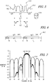
- FIG. 4 illustrates the forming of a symbol vector by summing a collection of delayed Nyquist pulses in accordance with some embodiments.
- an ensemble of k complex Nyquist pulses 402 maybe combined to generate a signal P(t) 410.
- the real part of the pulses p k (t) is represented in the figure.
- delayed versions of the pulses are added to define a symbol vector.
- FIG. 4 shows that that the Nyquist pulses create controlled ISI within a symbol vector and filter transients at the edges of the symbol vectors create interference between adjacent symbol vectors.
- the signal P(t) 410 is notional as the sketch does not show ISI.
- An output symbol vector for transmission by cyclic modulator 100 may be formed by summing a collection of k delayed Nyquist pulses.
- FIG. 5 illustrates the construction of a cyclic symbol vector in accordance with some embodiments.
- a cyclic symbol vector may be identified by adding in the symbol transients 502 outside of the central symbol vector 504. This can be envisioned as wrapping the symbol vector around a cylinder 506 of circumference equal to T v and then adding the portions that overlap onto the base symbol.
- the resultant cyclic symbol vector q(t) 508 may equivalently be formed by circular convolution of the QAM modulation pulses with a Nyquist filter.
- Cyclic symbol vector q(t) 508 may be constructed by summing the filter transients s 1 (t) and s 3 (t) 502 into the base symbol interval s 2 (t) 504. Cyclic symbol vector q(t) 508 may also be generated by cyclically convolving the filter response with the complex modulation pulses. The cyclic symbol vectors may be cyclically extended (by the TD mapping element 112 ( FIG. 1 )) prior to transmission by sending a segment, q ⁇ k ( t ) , from the end of the symbol prior to the base symbol, q k (t).
- FIG. 6 illustrates a train of train of cyclically extended symbol vectors in accordance with some embodiments.
- the train of cyclically extended symbol vectors 602 may be transmitted by the cyclic modulator 100 ( FIG. 1 ).
- This demonstrative waveform construction may be useful to illustrate the structural properties of the NCM waveform, which may be transmitted by cyclic modulator 100.
- the cyclic modulator 100 may accept a set of data streams that are serialized then presented to an encoder, such as a forward-error correcting (FEC) encoder.
- FEC forward-error correcting
- a pseudorandom sequence generator may be used to sustain channel operation, scramble user data, and for testing.
- a preamble e.g., a symbol vector pilot
- the resulting bit stream i.e., data stream 101
- symbol mapper 102 may be converted to QAM symbols by symbol mapper 102 then presented to an N-length Fast Fourier Transform (FFT) in transform element 104.
- FFT Fast Fourier Transform
- Information in the transform domain may be cyclically expanded by expansion element 106 and then root-Nyquist filtered in the frequency domain by alteration element 108.
- the root-Nyquist filtering may be a complex vector multiplication as opposed to a time-domain convolution and so it is more efficient.
- the frequency domain vector may be transformed into a cyclic symbol vector via an M-length inverse FFT by transform element 110 (i.e., M may be greater than N).
- a guard interval is added (i.e., time domain cyclic extension) by time-domain mapping element 112 and the result may be serialized (by P/S converter 114).
- dual D/A converters may be used produce a baseband signal representation that is transmitted via RF circuitry 118.
- cyclic modulator 100 may generate a cyclic waveform as described above in which the first transform element 104, the expansion element 106, the alteration element 108, and the second transform element 110 are configured to efficiently operate on parallel streams.
- the symbol vector 103 may contains 64 modulation symbols represented at 2 samples per symbol.
- the cyclic modulator 100 may produce symbol vectors at a 5 GHz ⁇ N which is a 78 MHz rate.
- the demodulator 200 may accept quadrature samples and the acquisition process establishes basic timing alignment and frequency error from the cyclic extension in accordance with conventional techniques.
- the frequency may be tracked continuously and sample timing adjusted by varying integral sample delay and fractional sample tracking as a linear phase shift yielding a uniform, adjustable group delay in an adaptive frequency domain equalizer.
- a subset of samples may be converted to parallel format (e.g., by S/P converter 206) and processed through an M-length FFT (e.g. by transform element 210).
- Matched root-Nyquist filtering may be performed by the alteration element 108 along with compensation for other known circuit dispersion (e.g., D/A and A/D converter droop and analog baseband filter effects).
- This adaptive equalization process performed by the alteration element 108 may help mitigate cyclic ISI.
- the equalized vector output may be reduced to the N-length IFFT (by transform element 216) and eventually streamed to a symbol-to-bit mapper to generate demodulated symbols which may be FEC decoded then formatted for a user interface.
- the modulator and demodulator architecture illustrated in FIGs. 1 and 2 may be replicated and the channels interconnected to support subband processing with spatial multiplexing techniques.
- the acquisition process applies pilot symbol vectors to sound the channel and estimates the channel matrix at the discrete frequencies. Channel variations for different modem deployments may vary. Channel dynamics in airborne collection applications may be estimated for compensation updates at a 10 Hz rate. Therefore, channel estimation and correction matrix computations may be addressable in a signal processor.
- FIG. 7 illustrates an estimate of NCM analog power spectral density in accordance with some embodiments.
- the cyclic structure may be applied in the modulator to control ISI and mitigate the impact of the RF dispersion. Residual dispersion may be addressed by the cyclic extension and adaptive equalization.
- a signal that carries 25 Gbps using 32 QAM and operates at a 5 GHz symbol rate and a 10 GHz sample rate.
- An estimate of the NCM analog power spectral density 704 is shown in FIG. 7 .
- the spectrum passband of 5 GHz 702 occurs at about the -5 dB point of the spectrum.
- the Sin(x)/x shaped curve 706 is included in the plot for comparison and represents a spectrum with no filtering applied.
- cyclic modulator 100 ( FIG. 1 ) and demodulator 200 ( FIG. 2 ) are illustrated as having several separate functional elements, one or more of the functional elements may be combined and may be implemented by combinations of software-configured elements, such as processing elements including digital signal processors (DSPs), and/or other hardware elements.
- processing elements including digital signal processors (DSPs), and/or other hardware elements.
- DSPs digital signal processors
- some elements may comprise one or more microprocessors, DSPs, field-programmable gate arrays (FPGAs), application specific integrated circuits (ASICs), radio-frequency integrated circuits (RFICs) and combinations of various hardware and logic circuitry for performing at least the functions described herein.
- the functional elements may refer to one or more processes operating on one or more processing elements.
- a modem for a MODEM for millimeter-wave communications may comprise one or more processing elements arranged to perform a first N-point FFT on an input symbol vector of QAM symbols to generate a transformed input vector in a transform domain, cyclically extend the transformed input symbol vector by adding symbol content outside a central symbol vector to generate an expanded symbol vector, weight at least some elements of the expanded symbol vector with a weighting vector selected for pulse shaping to generate a weighted symbol vector, perform an M-point IFFT on the weighted symbol vector to generate an output symbol vector for subsequent processing and transmission, and apply a mapping to the output symbol vector to generate a parallel set of output time samples.
- M may be greater than N.
- the one or more processing elements may be arranged to perform a root-Nyquist filtering process by complex vector multiplication in the frequency domain.
- Embodiments may be implemented in one or a combination of hardware, firmware and software. Embodiments may also be implemented as instructions stored on a computer-readable storage device, which may be read and executed by at least one processor to perform the operations described herein.
- a computer-readable storage device may include any non-transitory mechanism for storing information in a form readable by a machine (e.g., a computer).
- a computer-readable storage device may include read-only memory (ROM), random-access memory (RAM), magnetic disk storage media, optical storage media, flash-memory devices, and other storage devices and media.
- system 100 may include one or more processors and may be configured with instructions stored on a computer-readable storage device.
Landscapes
- Engineering & Computer Science (AREA)
- Signal Processing (AREA)
- Computer Networks & Wireless Communication (AREA)
- Physics & Mathematics (AREA)
- Discrete Mathematics (AREA)
- General Physics & Mathematics (AREA)
- Mathematical Physics (AREA)
- Spectroscopy & Molecular Physics (AREA)
- Power Engineering (AREA)
- Transmitters (AREA)
- Digital Transmission Methods That Use Modulated Carrier Waves (AREA)
Description
- Embodiments pertain to wireless communications. Some embodiments relate to communicating with cyclic waveforms. Some embodiments relate to the application of Nyquist cyclic modulation (NCM) to millimeter-wave wireless communications.
- For wireless communications, it is desirable that the modulation structure be amenable to robust operation and implementation efficiency. The selection of a modulation technique is critical for high rate wireless to support spectrally efficiency, detection efficiency, simplified acquisition, low peak-to-average power ratios (PAPRs), minimal channel dispersion, and reduced implementation complexity.
- Thus, there are general needs for improved modulators and demodulators that provide spectral efficiency, detection efficiency, simplified acquisition, low PAPR, minimal channel dispersion, and reduced implementation complexity.
-
US 2010/098182 A1 discloses a method and an OFDM device for SC-FDMA data transmission, in which a sequence of input data is transformed by means of a discrete transformation as transformed data signals of coded and modulated data signals on first frequency channels into a first frequency space over a first number of frequencies. The transformed data signals are mapped on second frequency channels in a second frequency space with a larger second number of frequencies. The transformed data signals on the second frequency channels are inverse-transformed using an inverse transformation. Data inversely transformed in such a way are provided for transmission. The transformed data signals are mapped into a frequency range of the second frequency channels in such a way that a constant component of the transformed data signals is mapped centrally within the frequency range. -
EP 1868336 A2 discloses a transmitter including a time/frequency-domain converter that converts a time-domain data signal to a frequency-domain data signal of a fixed number (N DFT); a subcarrier allocator that allocates the obtained frequency-domain data signal to any of (N IFFT) subcarriers, the number of which exceeds the fixed number (N DFT), the subcarriers being allocated in a predetermined transmission frequency Band; and a controller that controls the subcarrier allocator to allocate pilots or PAPR reduction signals to subcarriers in the idle band where the data signal is not allocated. By this, without the need for a plurality of time/frequency-domain conversion circuits with a large size, such as DFTs, frequency utilization efficiency (data transmission efficiency) is improved. -
US 8090037 B1 discloses reducing peak-to-average power ratio ("PAPR") for modulation and demodulation. Complex sample values are obtained in a time domain for orthogonal frequency division multiplexed ("OFDM") signaling. The complex sample values are transformed into a frequency domain. The set of spectral samples is multiplied with a filter spectrum to shape the set of spectral samples to provide spectral products. - In one aspect, the present disclosure provides a system for communicating using shaped cyclic time-domain waveforms comprising a cyclic modulator having one or more processing elements arranged to: perform a first transform on an input symbol vector to generate a transformed input symbol vector in a frequency domain; extend the transformed input symbol vector in the frequency domain to generate an expanded symbol vector; weight, in the frequency domain, each element of the expanded symbol vector with a weighting vector selected for Nyquist-pulse shaping to generate a weighted symbol vector; and perform a second transform on the weighted symbol vector to generate an output symbol vector for subsequent processing and transmission, the output symbol vector comprising a time-domain symbol vector, wherein the second transform is an inverse of the first transform and the second transform comprises a greater number of points than the first transform, wherein extending the transformed input signal vector in the frequency domain aperture creates an extended frequency domain aperture, wherein to generate the expanded symbol vector, the one or more processing elements may be arranged to cyclically extend the transformed input symbol vector by adding symbol content outside a central symbol vector to generate a resultant cyclic symbol vector, and wherein the resultant cyclic symbol vector corresponds to a circular convolution of the QAM symbols with a Nyquist filter response.
- In another aspect, the present disclosure provides a method for generating a shaped cyclic time-domain waveform comprising: performing a first N-point fast-Fourier transform 'FFT' on an input symbol vector of QAM symbols to generate a transformed input symbol vector in a frequency domain; cyclically extending the transformed input symbol vector in the frequency domain by adding symbol content outside a central symbol vector to generate an expanded symbol vector; weighting, in the frequency domain, each element of the expanded symbol vector with a weighting vector selected for Nyquist-pulse shaping to generate a weighted symbol vector; performing an M-point inverse FFT 'IFFT' on the weighted symbol vector to generate an output symbol vector for subsequent processing and transmission, the output symbol vector comprising a time-domain symbol vector, and applying a mapping to the output symbol vector to generate a parallel set of output time samples, wherein M is greater than N, wherein extending the transformed input symbol vector in the frequency domain creates an extended frequency domain aperture, and wherein the expanded symbol vector is a resultant cyclic symbol vector which corresponds to a circular convolution of the QAM symbols with a Nyquist filter response.
-
-
FIG. 1 is a functional diagram of a cyclic modulator in accordance with some embodiments; -
FIG. 2 is a block diagram of a demodulator in accordance with some embodiments; -
FIG. 3 illustrates Nyquist filtering of complex symbols in accordance with some embodiments; -
FIG. 4 illustrates the forming of a symbol vector by summing a collection of delayed Nyquist pulses in accordance with some embodiments; -
FIG. 5 illustrates the construction of a cyclic symbol vector in accordance with some embodiments; -
FIG. 6 illustrates a train of cyclically extended symbol vectors in accordance with some embodiments; and -
FIG. 7 illustrates an estimate of NCM analog power spectral density in accordance with some embodiments. - The following description and the drawings sufficiently illustrate specific embodiments to enable those skilled in the art to practice them. Other embodiments may incorporate structural, logical, electrical, process, and other changes. Portions and features of some embodiments may be included in, or substituted for, those of other embodiments. The embodiments which do not fall within the scope of the claims are to be interpreted as example useful for understanding the invention.
FIG. 1 is a functional diagram of a cyclic modulator in accordance with some embodiments.Cyclic modulator 100 may be configured to communicate shaped cyclic time-domain waveforms. A demodulator, such as demodulator 200 (FIG. 2 ), may be used to demodulate signals transmitted by thecyclic modulator 100. As described in more detail below, a process for extending a cyclic block at themodulator 100 and contracting the cyclic block at thedemodulator 200 is provided. This process may support shaping of the cyclic blocks for the spectral containment and may support adjustment of signal peak-to-average power ratio, among other things. In some embodiments, the expansion and contraction process may allow mid-frequency domain signal shaping. - In these embodiments, the
cyclic modulator 100 may have one or more processing elements arranged to perform a first transform on aninput symbol vector 103 to generate atransformed input vector 105 in a transform domain (e.g., the frequency domain). The one or more processing elements may also be arranged to extend the transformedinput symbol vector 105 to generate an expandedsymbol vector 107 and weight at least some elements of the expandedsymbol vector 107 with aweighting vector 127 selected for pulse shaping to generate a weightedsymbol vector 109. The one or more processing elements may also be arranged to perform a second transform on the weightedsymbol vector 109 to generate anoutput symbol vector 111 for subsequent processing and transmission. Theoutput symbol vector 111 may comprise a time-domain symbol vector. The second transform may be the inverse of the first transform and the second transform may comprise a greater number of points than the first transform. - After subsequent processing of the
output symbol vector 111,cyclic modulator 100 may transmit a shaped cyclic time-domain waveform 119 with one or more antennas. The shaped cyclic time-domain waveform 119 maybe a pulse-shaped waveform. These embodiments are described in more detail below. - As illustrated in
FIG. 1 , the first transform may be performed bytransform element 104, the expansion of the transformedinput symbol vector 105 may be performed byexpansion element 106, the weighting of the elements of the expandedsymbol vector 107 may be performed by alteration element 108, and the second transform may be performed bytransform element 110. - In some embodiments that implement Nyquist filtered cyclic modulation (NCM),
cyclic modulator 100 may transmit an NCM waveform that provides low PAPR, inherent rejection of channel dispersion and reduced acquisition complexity. In some embodiments, a parallel implementation of thecyclic modulator 100 may support multi-gigabit-per-second modems. These embodiments are described in more detail below. - In some embodiments, the first transform (performed by transform element 104) may be an N-point (or N-length) fast-Fourier transform (FFT) to transform the
input symbol vector 103 to the frequency domain and the second transform (performed by transform element 110) may be an M-point (or M-length) inverse FFT (IFFT) to transform the expandedsymbol vector 107 to the time-domain. In these embodiments M and N are whole numbers and M is greater than N. - In some example embodiments, N may be 64 and M may be 128, although the scope of the embodiments is not limited in this respect as M may be any number greater than N and less than 512, for example. In some embodiments, N may be 64 and M may be around 100. In some embodiments, N may correspond to the number of elements of the
input symbol vector 103 and M may correspond to the number of elements of the expandedsymbol vector 107 as well as the number of elements of the weightedsymbol vector 109. In some embodiments, the symbol vectors may be ordered lists of elements (e.g., tuples). - In some embodiments, transforms other than an FFT for the first transform and an IFFT for the second transform may be used. For example, the first transform may be a discrete Fourier transform (DFT) and the second transform may be an inverse discrete Fourier transform (IDFT).
- In accordance with embodiments, to generate the expanded
symbol vector 107, theexpansion element 106 may be arranged to add at least M-N elements to thetransformed input vector 105. In some embodiments, this added expansion may support a larger frequency domain. In some embodiments, each element (instead of just some of the elements) of the expandedsymbol vector 107 may be weighted with aweighting vector 127. - In some embodiments, the
input symbol vector 103 may comprise quadrature-amplitude modulation (QAM) symbols or modulation pulses. To generate the expandedsymbol vector 107, theexpansion element 106 may be arranged to cyclically extend the transformedinput vector 105 by adding symbol content outside a central symbol vector to generate a resultant cyclic symbol vector q(t) (i.e., the expanded symbol vector 107). Examples of this are illustrated inFIG. 5 described below. The resultant cyclic symbol vector q(t) may correspond to a circular convolution of the QAM symbols with a Nyquist filter response. - In some embodiments, to weight at least some elements of the expanded
symbol vector 107, the alteration element 108 may be arranged to perform a root-Nyquist filtering process by complex vector multiplication in the frequency domain. In these embodiments, the weights ofweighting vector 127 may be selected to perform Nyquist shaping in accordance with the Nyquist filter response (i.e., for NCM). Other shaping, such as Butterworth shaping, may alternatively be performed. - In some embodiments, some weights of the
weighting vector 127 may have a zero value and some weights having non-zero values. In these embodiments, the non-zero valued weights may be applied to elements that are to be operated on by the second transform. - In accordance with some embodiments, a filter with finite time-domain support may be used as part of the filtering process performed by alteration element 108. In this way, after filtering, the inverse transform of the weighted frequency domain signal (i.e., the second transform performed by transform element 110) may result in a filtered time-domain signal where the transients (of infinite extent) will appear to have wrapped into the symbol vector in a cyclic manner. In these embodiments, the extent of the frequency domain filter representation may be limited to approximate a filter with greater frequency support (e.g., those frequencies where the values of the filter are non-zero). In these embodiments, the original filter may be non-zero over a larger range but is approximated with a filter that is shorter (e.g., zero over an extended frequency range).
- In some embodiments, the expansion of the transformed input vector 105 (i.e., by expansion element 106) to generate the expanded
symbol vector 107 may comprise extending an aperture in the frequency domain. In these embodiments, an aperture may refer to a segment of samples that may be considered significant. For example, when there are 64 points in the first transform output, the frequency domain aperture may have a length of 64 (i.e., 64 samples). When there are 128 points in the second transform, the second transform may have an aperture of length 128 (i.e., 128 samples). The expansion added byexpansion element 106 may establish a map between these two apertures that behaves in a manner that is desirable for a particular application (e.g., to perform well controlled filtering). - In some embodiments, the modulation symbols that comprise
output symbol vector 111 as presented by the second transform may be twice oversampled. - In some embodiments, the one or more processing elements of the
cyclic modulator 100 may further be arranged to apply a mapping to theoutput symbol vector 111 to generate a parallel set of output time samples 113. In these embodiments, the mapping applied to theoutput symbol vector 111 may be applied by time-domain (TD)mapping element 112. - In some embodiments, the
output symbol vector 111 may comprise an in-phase signal (I) and quadrature signal (Q) (i.e., complex modulation symbols). The mapping that is applied may be arranged to cyclically extend the output symbol vector 111 (which is a time-domain symbol vector) and cyclically shift the quadrature signal by one-half symbol from the in-phase signal to produce an offset modulated signal block corresponding to the output time samples 113. - The output time samples 113 may be converted from parallel to serial form by parallel-to-serial (P/S)
converter 114 to generate time samples 115 (e.g., digital baseband signals) which may be converted to analog form by digital-to-analog converter (DAC) 116 for subsequent up-conversion to RF signals byRF circuitry 118 and for transmission by one or more antennas. - As further illustrated in
FIG. 1 , prior to performance of the first transform bytransform element 104, adata stream 101 may be converted to parallel form and may undergo a bit-to-symbol mapping process to generate theinput symbol vector 103. Modulation formats may include standard modulation formats (e.g., PSK and QAM formats) as well as offset modulation formats. -
FIG. 2 is a block diagram of a demodulator in accordance with some embodiments.Demodulator 200 may be suitable for the demodulation of a shaped cyclic time-domain waveform that may have been transmitted by a cyclic modulator, such as cyclic modulator 100 (FIG. 1 ), although the scope of the embodiments is not limited in this respect. In some embodiments,cyclic modulator 100 anddemodulator 200 may comprise a modem or may be part of a wireless communication system. - In accordance with embodiments, the
demodulator 200 may comprise one or more processing elements arranged to perform a third transform on a time-domain symbol vector 209 generated from a receivedsignal 201. The third transform may convert the time-domain symbol vector 209 to a frequency-domain representation 211. The processing elements of thedemodulator 200 may also be arranged to perform a frequency-domain weighting at least some elements of the frequency-domain representation 211 (e.g., by application of a weighting vector 227) to generate a weighted symbol vector 213, and perform a compression process on the weighted symbol vector 213 to produce a corrected symbol vector 215 having a reduce number of elements (i.e., symbols). The processing elements of thedemodulator 200 may also be arranged to perform a fourth transform on only some elements of the corrected symbol vector 215 to generate anoutput signal vector 217 that is an estimate of transmitted modulation symbols. The third transform may be an inverse of the fourth transform and the third transform may comprise a greater number of points than the fourth transform. - In these embodiments, frequency-domain weighting may be performed by
alteration element 212 and may be responsible for matched recovery and equalization of general time-domain symbol pulse shapes. In some embodiments, the third transform may be performed bytransform element 210, the compression process may be performed bycompression process element 214, and the fourth transform may be performed byfourth transform element 216. In these embodiments, the compression process may compress the number of values being processed. - In some embodiments, the third transform (i.e., performed by transform element 210) may be an inverse of the second transform (i.e., performed by
transform element 110 of the cyclic modulator 100 (FIG. 1 )) and has the same number of points as the second transform. The fourth transform (i.e., performed by transform element 216) may be an inverse of the first transform (i.e., performed bytransform element 104 of the cyclic modulator 100) and may have the same number of points as the first transform although the scope of the embodiments is not limited in this respect. - In some alternate embodiments, the fourth transform (i.e., performed by transform element 216) may have a different number of points as the first transform (i.e., performed by transform element 104). In these alternate embodiments, the fourth transform may be an M-point size transform (e.g., rather than an N-point size transform) to detect and equalize the offset symbols.
- In some embodiments, the processing elements of the
demodulator 200 may also be arranged to discard theelements 225 of the corrected symbol vector 215 that are not to be operated on by the fourth transform. The elements that are retained may correspond to the elements that were added by theexpansion element 106 of thecyclic modulator 100. - In some embodiments, the
compression process element 214 may support a reduction of samples for more efficient recovery processing. As illustrated inFIG. 2 ,compression process element 214 may operate on the weighted symbol vector 213, which may have M elements, however this is not a requirement as thecompression process element 214 may operate on a subset of these elements (e.g., N elements of vector 213). - In some embodiments, the third transform may be an M-point FFT, and the fourth transform is an N-point IFFT. M and N may be whole numbers and M may be greater than N.
- In some embodiments, the frequency-domain weighting (i.e., performed by the alternation element 212) may apply a mapping that cyclically filters the signal (i.e., the frequency-domain representation 211). In some embodiments, the mapping may act as an adaptive frequency-domain filter or equalizer.
- In some embodiments, the
demodulator 200 may also include time-domain mapping element 208 to apply a mapping to a received time-domain signal 207 to produce the time-domain symbol vector 209 for performance of the third transform thereon. In these embodiments, the mapping applied to the received time-domain signal 207 may be a time-domain format process performed by the time-domain mapping element 208. In some embodiments, the mapping applied to received time-domain signal 207 may be an inverse of the mapping applied by time-domain mapping element 112 (FIG. 1 ) of the cyclic modulator 100 (FIG. 1 ). In some embodiments, the mapping may identify and remove a cyclic extension from the received time-domain signal 207 and may cyclically shift the quadrature component of the baseband waveform by one-half symbol (e.g., relative to the in-phase component) to map an offset modulation to a non-offset format to producesymbol vector 209. - As illustrated in
FIG. 2 ,demodulator 200 may also includeRF recovery circuitry 202 to process the receivedRF signal 201 and analog-to-digital converter (ADC) 204 to perform filtering and convert the received signal todigital baseband samples 205. Serial-to-parallel (S/P) converter 206 may generate the received time-domain signal 207 from thebaseband samples 205.Demodulator 200 may also include P/S converter anddata decision circuitry 218 to generate decision values from theoutput signal vector 217 for mapping to the output data 219. Although not specifically discussed,demodulator 200 may be configured to compensate for frequency offset induced by the RF, as well as address cyclic vector alignment in accordance with conventional techniques. -
FIG. 3 illustrates Nyquist filtering of complex symbols in accordance with some embodiments. As shown inFIG. 3 , pulses scaled with a QAM constellation 302 (e.g., 4-QAM (i.e., QPSK) or 32 QAM) may be Nyquist filtered byNyquist filter 304 to produce acomplex pulse train 306. In practice, theNyquist filter 304 may be divided into root-Nyquist filters that may serve to band limit and pulse shape at the transmitter (e.g., cyclic modulator 100 (FIG. 1 )) and act as the matched filter at the receiver (e.g., demodulator 200 (FIG. 2 )). In these embodiments, the Nyquist filters exhibit a property that the modulation bandwidth is well constrained and there is little or no inter-symbol interference (ISI) at the symbol sampling instance. The pulses may be sampled at two-samples per symbol to help avoid interpolation in recovery and the D/A reconstruction filters may be specifically configured depending on the Nyquist shape factor. Nyquist pulses have a well contained spectrum and zero ISI at the sample instance. As illustrated inFIG. 3 , pulses cross zero at the adjacent symbol peaks. -
FIG. 4 illustrates the forming of a symbol vector by summing a collection of delayed Nyquist pulses in accordance with some embodiments. As illustrated inFIG. 4 , an ensemble of kcomplex Nyquist pulses 402 maybe combined to generate a signal P(t) 410. The real part of the pulses pk(t) is represented in the figure. As illustrated, delayed versions of the pulses are added to define a symbol vector.FIG. 4 shows that that the Nyquist pulses create controlled ISI within a symbol vector and filter transients at the edges of the symbol vectors create interference between adjacent symbol vectors. Note that the signal P(t) 410 is notional as the sketch does not show ISI. An output symbol vector for transmission by cyclic modulator 100 (FIG. 1 ) may be formed by summing a collection of k delayed Nyquist pulses. -
FIG. 5 illustrates the construction of a cyclic symbol vector in accordance with some embodiments. A cyclic symbol vector may be identified by adding in thesymbol transients 502 outside of thecentral symbol vector 504. This can be envisioned as wrapping the symbol vector around acylinder 506 of circumference equal to Tv and then adding the portions that overlap onto the base symbol. The resultant cyclic symbol vector q(t) 508 may equivalently be formed by circular convolution of the QAM modulation pulses with a Nyquist filter. - Cyclic symbol vector q(t) 508 may be constructed by summing the filter transients s1(t) and s3(t) 502 into the base symbol interval s2(t) 504. Cyclic symbol vector q(t) 508 may also be generated by cyclically convolving the filter response with the complex modulation pulses. The cyclic symbol vectors may be cyclically extended (by the TD mapping element 112 (
FIG. 1 )) prior to transmission by sending a segment, q̃k (t), from the end of the symbol prior to the base symbol, qk(t). -
FIG. 6 illustrates a train of train of cyclically extended symbol vectors in accordance with some embodiments. The train of cyclically extendedsymbol vectors 602 may be transmitted by the cyclic modulator 100 (FIG. 1 ). This demonstrative waveform construction may be useful to illustrate the structural properties of the NCM waveform, which may be transmitted bycyclic modulator 100. - Referring to
FIG. 1 , in accordance with some embodiments, thecyclic modulator 100 may accept a set of data streams that are serialized then presented to an encoder, such as a forward-error correcting (FEC) encoder. A pseudorandom sequence generator may be used to sustain channel operation, scramble user data, and for testing. A preamble (e.g., a symbol vector pilot) may be periodically inserted in the stream. The resulting bit stream (i.e., data stream 101) may be converted to QAM symbols bysymbol mapper 102 then presented to an N-length Fast Fourier Transform (FFT) intransform element 104. Information in the transform domain may be cyclically expanded byexpansion element 106 and then root-Nyquist filtered in the frequency domain by alteration element 108. In these embodiments, the root-Nyquist filtering may be a complex vector multiplication as opposed to a time-domain convolution and so it is more efficient. The frequency domain vector may be transformed into a cyclic symbol vector via an M-length inverse FFT by transform element 110 (i.e., M may be greater than N). A guard interval is added (i.e., time domain cyclic extension) by time-domain mapping element 112 and the result may be serialized (by P/S converter 114). In some embodiments, dual D/A converters may be used produce a baseband signal representation that is transmitted viaRF circuitry 118. In these embodiments,cyclic modulator 100 may generate a cyclic waveform as described above in which thefirst transform element 104, theexpansion element 106, the alteration element 108, and thesecond transform element 110 are configured to efficiently operate on parallel streams. In an example embodiment in which M is 128 and N is 64, thesymbol vector 103 may contains 64 modulation symbols represented at 2 samples per symbol. For a symbol rate of 5 GHz, thecyclic modulator 100 may produce symbol vectors at a 5 GHz ÷ N which is a 78 MHz rate. - In accordance with embodiments, the demodulator 200 (
FIG. 2 ) may accept quadrature samples and the acquisition process establishes basic timing alignment and frequency error from the cyclic extension in accordance with conventional techniques. The frequency may be tracked continuously and sample timing adjusted by varying integral sample delay and fractional sample tracking as a linear phase shift yielding a uniform, adjustable group delay in an adaptive frequency domain equalizer. Given alignment to within the extended cyclic symbol vector, a subset of samples may be converted to parallel format (e.g., by S/P converter 206) and processed through an M-length FFT (e.g. by transform element 210). Matched root-Nyquist filtering may be performed by the alteration element 108 along with compensation for other known circuit dispersion (e.g., D/A and A/D converter droop and analog baseband filter effects). This adaptive equalization process performed by the alteration element 108 may help mitigate cyclic ISI. The equalized vector output may be reduced to the N-length IFFT (by transform element 216) and eventually streamed to a symbol-to-bit mapper to generate demodulated symbols which may be FEC decoded then formatted for a user interface. - In some embodiments, the modulator and demodulator architecture illustrated in
FIGs. 1 and 2 may be replicated and the channels interconnected to support subband processing with spatial multiplexing techniques. In some embodiments, the acquisition process applies pilot symbol vectors to sound the channel and estimates the channel matrix at the discrete frequencies. Channel variations for different modem deployments may vary. Channel dynamics in airborne collection applications may be estimated for compensation updates at a 10 Hz rate. Therefore, channel estimation and correction matrix computations may be addressable in a signal processor. -
FIG. 7 illustrates an estimate of NCM analog power spectral density in accordance with some embodiments. As discussed above, the cyclic structure may be applied in the modulator to control ISI and mitigate the impact of the RF dispersion. Residual dispersion may be addressed by the cyclic extension and adaptive equalization. Consider a signal that carries 25 Gbps using 32 QAM and operates at a 5 GHz symbol rate and a 10 GHz sample rate. An estimate of the NCM analog powerspectral density 704 is shown inFIG. 7 . The spectrum passband of 5GHz 702 occurs at about the -5 dB point of the spectrum. The Sin(x)/x shapedcurve 706 is included in the plot for comparison and represents a spectrum with no filtering applied. - Although cyclic modulator 100 (
FIG. 1 ) and demodulator 200 (FIG. 2 ) are illustrated as having several separate functional elements, one or more of the functional elements may be combined and may be implemented by combinations of software-configured elements, such as processing elements including digital signal processors (DSPs), and/or other hardware elements. For example, some elements may comprise one or more microprocessors, DSPs, field-programmable gate arrays (FPGAs), application specific integrated circuits (ASICs), radio-frequency integrated circuits (RFICs) and combinations of various hardware and logic circuitry for performing at least the functions described herein. In some embodiments, the functional elements may refer to one or more processes operating on one or more processing elements. - In some embodiments, a modem for a MODEM for millimeter-wave communications is provided. In these embodiments, the modem may comprise one or more processing elements arranged to perform a first N-point FFT on an input symbol vector of QAM symbols to generate a transformed input vector in a transform domain, cyclically extend the transformed input symbol vector by adding symbol content outside a central symbol vector to generate an expanded symbol vector, weight at least some elements of the expanded symbol vector with a weighting vector selected for pulse shaping to generate a weighted symbol vector, perform an M-point IFFT on the weighted symbol vector to generate an output symbol vector for subsequent processing and transmission, and apply a mapping to the output symbol vector to generate a parallel set of output time samples.
- In these embodiments, M may be greater than N. To weight at least some elements of the expanded symbol vector, the one or more processing elements may be arranged to perform a root-Nyquist filtering process by complex vector multiplication in the frequency domain.
- Embodiments may be implemented in one or a combination of hardware, firmware and software. Embodiments may also be implemented as instructions stored on a computer-readable storage device, which may be read and executed by at least one processor to perform the operations described herein. A computer-readable storage device may include any non-transitory mechanism for storing information in a form readable by a machine (e.g., a computer). For example, a computer-readable storage device may include read-only memory (ROM), random-access memory (RAM), magnetic disk storage media, optical storage media, flash-memory devices, and other storage devices and media. In some embodiments,
system 100 may include one or more processors and may be configured with instructions stored on a computer-readable storage device.
Claims (14)
- A system for communicating using shaped cyclic time-domain waveforms comprising a cyclic modulator (100) having one or more processing elements arranged to:perform a first transform on an input symbol vector (103) to generate a transformed input symbol vector (105) in a frequency domain;extend the transformed input symbol vector (105) in the frequency domain to generate an expanded symbol vector (107);weight, in the frequency domain, each element of the expanded symbol vector (107) with a weighting vector (127) selected for Nyquist-pulse shaping to generate a weighted symbol vector (109); andperform a second transform on the weighted symbol vector (109) to generate an output symbol vector (111) for subsequent processing and transmission, the output symbol vector (111) comprising a time-domain symbol vector,wherein the second transform is an inverse of the first transform and the second transform comprises a greater number of points than the first transform,wherein extending the transformed input signal vector (105) in the frequency domain aperture creates an extended frequency domain aperture,wherein the input symbol vector (103) comprises quadrature-amplitude modulation 'QAM' symbols,wherein to generate the expanded symbol vector (107), the one or more processing elements may be arranged to cyclically extend the transformed input symbol vector (105) by adding symbol content (502) outside a central symbol vector (504) to generate a resultant cyclic symbol vector (508), andwherein the resultant cyclic symbol vector (508) corresponds to a circular convolution of the QAM symbols with a Nyquist filter response.
- The system of claim 1 wherein the first transform is an N-point fast-Fourier transform 'FFT' to transform the input symbol vector to the frequency domain and the second transform is an M-point inverse FFT 'IFFT' to transform the expanded symbol vector to the time-domain,
wherein M is greater than N, and
wherein to generate the expanded symbol vector, the one or more processing elements is arranged to add at least M-N elements to the transformed input vector. - The system of claim 1 wherein to weight at least some elements of the expanded symbol vector (107), the one or more processing elements are arranged to perform a root-Nyquist filtering process by complex vector multiplication in the frequency domain.
- The system of claim 3 wherein the expansion of the transformed input symbol vector (105) to generate the expanded symbol vector (107) comprises extending an aperture in the frequency domain to create the extended frequency domain aperture.
- The system of claim 3 wherein the processing elements are further arranged to apply a mapping to the output symbol vector (111) to generate a parallel set of output time samples (113).
- The system of claim 5 wherein the output symbol vector (111) comprises an in-phase signal 'I' and quadrature signal 'Q', and
wherein the mapping that is applied is arranged to cyclically extend the output symbol vector (111) and cyclically shift the quadrature signal by one-half symbol from the in-phase signal to produce an offset modulated signal block corresponding to the output time samples (113). - The system of claim 1 further comprising a demodulator (200) comprising one or more processing elements arranged to:perform a third transform on a time-domain symbol vector (209) generated from a received signal (201) comprising a shaped cyclic time-domain waveform, the third transform to convert the time-domain symbol vector (209) to a frequency-domain representation (211);perform a frequency-domain weighting at least some elements of the frequency-domain representation (211) to generate a weighted symbol vector (213);perform a compression process on the weighted symbol vector (213) to produce a corrected symbol vector (215) having a reduced number of elements; andperform a fourth transform on only some elements of the corrected symbol vector (215) to generate an output signal vector (217) that is an estimate of transmitted modulation symbols,wherein the third transform is an inverse of the fourth transform and the third transform comprises a greater number of points than the fourth transform.
- The system of claim 7 wherein the third transform is an inverse of the second transform and has the same number of points as the second transform, and
wherein the fourth transform is an inverse of the first transform and has a same number of points as the first transform. - The system of claim 7 wherein the one or more processing elements of the demodulator (200) is further arranged to discard elements of the corrected symbol vector (215) that are not operated on by the fourth transform.
- The system of claim 9 wherein the third transform is an M-point FFT and the fourth transform is an N-point IFFT, and
wherein M is greater than N. - The system of claim 10 wherein the frequency-domain weighting applies a mapping for cyclical filtering.
- The system of claim 11, wherein the one or more processing elements of the demodulator (200) are further arranged to apply a mapping to a received time-domain signal (207) to produce the time-domain symbol vector (209) for performance of the third transform thereon.
- A method for generating a shaped cyclic time-domain waveform comprising:performing a first N-point fast-Fourier transform 'FFT' on an input symbol vector (103) of QAM symbols to generate a transformed input symbol vector (105) in a frequency domain;cyclically extending the transformed input symbol vector (105) in the frequency domain by adding symbol content (502) outside a central symbol vector to generate an expanded symbol vector (107);weighting, in the frequency domain, each element of the expanded symbol vector (107) with a weighting vector (127) selected for Nyquist-pulse shaping to generate a weighted symbol vector (109);performing an M-point inverse FFT 'IFFT' on the weighted symbol vector to generate an output symbol vector (111) for subsequent processing and transmission, the output symbol vector (111) comprising a time-domain symbol vector, andapplying a mapping to the output symbol vector to generate a parallel set of output time samples (113),wherein M is greater than N,wherein extending the transformed input symbol vector (105) in the frequency domain creates an extended frequency domain aperture, andwherein the expanded symbol vector (107) is a resultant cyclic symbol vector (508) which corresponds to a circular convolution of the QAM symbols with a Nyquist filter response.
- The method of claim 13 wherein weighting comprises performing a root-Nyquist filtering process by complex vector multiplication in the frequency domain.
Applications Claiming Priority (2)
| Application Number | Priority Date | Filing Date | Title |
|---|---|---|---|
| US13/864,135 US8934556B2 (en) | 2013-04-16 | 2013-04-16 | System and method for communicating with shaped cyclic time-domain waveforms |
| PCT/US2014/034149 WO2014172343A1 (en) | 2013-04-16 | 2014-04-15 | System and method for communicating with shaped cyclic time-domain waveforms |
Publications (2)
| Publication Number | Publication Date |
|---|---|
| EP2987291A1 EP2987291A1 (en) | 2016-02-24 |
| EP2987291B1 true EP2987291B1 (en) | 2018-02-21 |
Family
ID=50736193
Family Applications (1)
| Application Number | Title | Priority Date | Filing Date |
|---|---|---|---|
| EP14725319.9A Active EP2987291B1 (en) | 2013-04-16 | 2014-04-15 | System and method for communicating with shaped cyclic time-domain waveforms |
Country Status (3)
| Country | Link |
|---|---|
| US (1) | US8934556B2 (en) |
| EP (1) | EP2987291B1 (en) |
| WO (1) | WO2014172343A1 (en) |
Families Citing this family (6)
| Publication number | Priority date | Publication date | Assignee | Title |
|---|---|---|---|---|
| US10893520B2 (en) * | 2015-08-26 | 2021-01-12 | Qualcomm Incorporated | Downlink and synchronization techniques for narrowband wireless communications |
| WO2017178871A1 (en) * | 2016-04-15 | 2017-10-19 | Indian Institute Of Technology Hyderabad | Method and transmitter for generating a waveform with optimized papr |
| US9853849B1 (en) | 2016-06-22 | 2017-12-26 | Frontier Analytics, LLC | Systems and methods to produce a cyclically generated, continuous phase, frequency shift keying waveform |
| CN108924077B (en) * | 2018-06-25 | 2020-10-30 | 哈尔滨工业大学 | Transmission method under time selective fading channel of generalized mixed carrier system |
| CN110708268B (en) * | 2019-09-25 | 2021-08-27 | 维沃移动通信有限公司 | Signal modulation device and terminal |
| CN112367133B (en) * | 2020-10-28 | 2022-11-11 | 西北工业大学 | Multi-domain switching communication method based on intelligent decision |
Citations (1)
| Publication number | Priority date | Publication date | Assignee | Title |
|---|---|---|---|---|
| US8090037B1 (en) * | 2008-10-28 | 2012-01-03 | Xilinx, Inc. | OFDM modulation using a shaping filter |
Family Cites Families (7)
| Publication number | Priority date | Publication date | Assignee | Title |
|---|---|---|---|---|
| JP2003204293A (en) * | 2002-01-08 | 2003-07-18 | Communication Research Laboratory | Compensation transmission method for phasing distortion or frequency offset |
| US9002299B2 (en) * | 2004-10-01 | 2015-04-07 | Cisco Technology, Inc. | Multiple antenna processing on transmit for wireless local area networks |
| KR101154979B1 (en) * | 2005-07-22 | 2012-06-18 | 엘지전자 주식회사 | apparatus for receiving and transmitting data of multi-carrier system and method for receiving and transmitting data using the same |
| JP2007329588A (en) | 2006-06-06 | 2007-12-20 | Fujitsu Ltd | Transmitter and transmission method |
| EP1936900A1 (en) | 2006-12-18 | 2008-06-25 | Nokia Siemens Networks Gmbh & Co. Kg | Method and OFDM device for SC-FDMA data transfer |
| JP5484682B2 (en) * | 2008-02-27 | 2014-05-07 | 富士通株式会社 | WIRELESS COMMUNICATION DEVICE, EQUALIZER, EQUALIZER WEIGHT COEFFICIENT PROGRAM AND Equalizer Weight Coefficient Calculation Method |
| US20100098042A1 (en) * | 2008-10-21 | 2010-04-22 | Paul Wilkinson Dent | Using the same multiplexed radio resource for pilot and information signals |
-
2013
- 2013-04-16 US US13/864,135 patent/US8934556B2/en active Active
-
2014
- 2014-04-15 WO PCT/US2014/034149 patent/WO2014172343A1/en not_active Ceased
- 2014-04-15 EP EP14725319.9A patent/EP2987291B1/en active Active
Patent Citations (1)
| Publication number | Priority date | Publication date | Assignee | Title |
|---|---|---|---|---|
| US8090037B1 (en) * | 2008-10-28 | 2012-01-03 | Xilinx, Inc. | OFDM modulation using a shaping filter |
Also Published As
| Publication number | Publication date |
|---|---|
| US8934556B2 (en) | 2015-01-13 |
| US20140307761A1 (en) | 2014-10-16 |
| WO2014172343A1 (en) | 2014-10-23 |
| EP2987291A1 (en) | 2016-02-24 |
Similar Documents
| Publication | Publication Date | Title |
|---|---|---|
| LaSorte et al. | The history of orthogonal frequency division multiplexing | |
| KR101588994B1 (en) | Pilot signal in an fdma communication system | |
| CN101267414B (en) | An Orthogonal Frequency Division Multiple Access Downlink Communication System and Communication Method | |
| US20140192925A1 (en) | Method of and apparatus for reducing papr in filter-bank multi-carrier system | |
| CN105009490B (en) | Sending device, receiving device and communication system | |
| US8934556B2 (en) | System and method for communicating with shaped cyclic time-domain waveforms | |
| CN105453462B (en) | Sending device, receiving device and communication system | |
| CN107113265B (en) | Efficient FBMC transmission and reception for multiple access communication systems | |
| CN109462443B (en) | 5G multi-carrier underwater acoustic communication method | |
| Ravindran et al. | Performance evaluation of 5G waveforms: UFMC and FBMC-OQAM with Cyclic Prefix-OFDM System | |
| CN106713207A (en) | Implementation method of multicarrier faster-than-Nyquisy system based on Fourier transform | |
| CN108900461B (en) | Wireless communication system broadband signal design method based on large-scale MIMO | |
| Abdullah | Interference mitigation techniques for wireless OFDM | |
| KR20050099905A (en) | Transmitting/receiving apparatus method for fast frequency hopping in orthogonal frequency division multiplex system and method therefor | |
| US20190349157A1 (en) | Receiver, transmitter, communication system for subband communication and methods for subband communication | |
| CN107438041B (en) | Method and device for sending signal and receiving signal | |
| Arthur et al. | Comparative analysis of orthogonal frequency division modulation and filter bank-based multicarrier modulation | |
| WO2017113073A1 (en) | Signal processing method, transmitter and receiver | |
| WO2017167386A1 (en) | A transmitter for transmitting and a receiver for receiving a plurality of multicarrier modulation signals | |
| CN1885844B (en) | Device for reducing peak-to-average ratio based on orthogonal multiplex multi-carrier transmission and its method | |
| Prethyoosha et al. | Performance analysis of DFT spreading and wavelet filtering in UFMC system | |
| JP6414850B2 (en) | TRANSMISSION DEVICE, RECEPTION DEVICE, TRANSMISSION METHOD, AND RECEPTION METHOD | |
| CN108605028A (en) | Method and apparatus for estimating and correcting phase error in a wireless communication system | |
| Naveena et al. | FBMC Modulation Schemes for 5G Mobile Communications | |
| Mestre et al. | Linear receivers for massive MIMO FBMC/OQAM under strong channel frequency selectivity |
Legal Events
| Date | Code | Title | Description |
|---|---|---|---|
| PUAI | Public reference made under article 153(3) epc to a published international application that has entered the european phase |
Free format text: ORIGINAL CODE: 0009012 |
|
| 17P | Request for examination filed |
Effective date: 20151112 |
|
| AK | Designated contracting states |
Kind code of ref document: A1 Designated state(s): AL AT BE BG CH CY CZ DE DK EE ES FI FR GB GR HR HU IE IS IT LI LT LU LV MC MK MT NL NO PL PT RO RS SE SI SK SM TR |
|
| AX | Request for extension of the european patent |
Extension state: BA ME |
|
| 17Q | First examination report despatched |
Effective date: 20160314 |
|
| DAX | Request for extension of the european patent (deleted) | ||
| REG | Reference to a national code |
Ref country code: DE Ref legal event code: R079 Ref document number: 602014021205 Country of ref document: DE Free format text: PREVIOUS MAIN CLASS: H04L0027260000 Ipc: H04L0027360000 |
|
| GRAP | Despatch of communication of intention to grant a patent |
Free format text: ORIGINAL CODE: EPIDOSNIGR1 |
|
| RIC1 | Information provided on ipc code assigned before grant |
Ipc: H04L 27/36 20060101AFI20170829BHEP Ipc: H04L 27/26 20060101ALI20170829BHEP Ipc: H04L 5/00 20060101ALI20170829BHEP Ipc: H04L 25/03 20060101ALI20170829BHEP |
|
| INTG | Intention to grant announced |
Effective date: 20170912 |
|
| GRAS | Grant fee paid |
Free format text: ORIGINAL CODE: EPIDOSNIGR3 |
|
| GRAA | (expected) grant |
Free format text: ORIGINAL CODE: 0009210 |
|
| AK | Designated contracting states |
Kind code of ref document: B1 Designated state(s): AL AT BE BG CH CY CZ DE DK EE ES FI FR GB GR HR HU IE IS IT LI LT LU LV MC MK MT NL NO PL PT RO RS SE SI SK SM TR |
|
| REG | Reference to a national code |
Ref country code: GB Ref legal event code: FG4D |
|
| REG | Reference to a national code |
Ref country code: CH Ref legal event code: EP |
|
| REG | Reference to a national code |
Ref country code: AT Ref legal event code: REF Ref document number: 972871 Country of ref document: AT Kind code of ref document: T Effective date: 20180315 |
|
| REG | Reference to a national code |
Ref country code: IE Ref legal event code: FG4D |
|
| REG | Reference to a national code |
Ref country code: DE Ref legal event code: R096 Ref document number: 602014021205 Country of ref document: DE |
|
| REG | Reference to a national code |
Ref country code: FR Ref legal event code: PLFP Year of fee payment: 5 |
|
| REG | Reference to a national code |
Ref country code: NL Ref legal event code: MP Effective date: 20180221 |
|
| REG | Reference to a national code |
Ref country code: LT Ref legal event code: MG4D |
|
| REG | Reference to a national code |
Ref country code: AT Ref legal event code: MK05 Ref document number: 972871 Country of ref document: AT Kind code of ref document: T Effective date: 20180221 |
|
| PG25 | Lapsed in a contracting state [announced via postgrant information from national office to epo] |
Ref country code: NL Free format text: LAPSE BECAUSE OF FAILURE TO SUBMIT A TRANSLATION OF THE DESCRIPTION OR TO PAY THE FEE WITHIN THE PRESCRIBED TIME-LIMIT Effective date: 20180221 Ref country code: HR Free format text: LAPSE BECAUSE OF FAILURE TO SUBMIT A TRANSLATION OF THE DESCRIPTION OR TO PAY THE FEE WITHIN THE PRESCRIBED TIME-LIMIT Effective date: 20180221 Ref country code: CY Free format text: LAPSE BECAUSE OF FAILURE TO SUBMIT A TRANSLATION OF THE DESCRIPTION OR TO PAY THE FEE WITHIN THE PRESCRIBED TIME-LIMIT Effective date: 20180221 Ref country code: ES Free format text: LAPSE BECAUSE OF FAILURE TO SUBMIT A TRANSLATION OF THE DESCRIPTION OR TO PAY THE FEE WITHIN THE PRESCRIBED TIME-LIMIT Effective date: 20180221 Ref country code: LT Free format text: LAPSE BECAUSE OF FAILURE TO SUBMIT A TRANSLATION OF THE DESCRIPTION OR TO PAY THE FEE WITHIN THE PRESCRIBED TIME-LIMIT Effective date: 20180221 Ref country code: NO Free format text: LAPSE BECAUSE OF FAILURE TO SUBMIT A TRANSLATION OF THE DESCRIPTION OR TO PAY THE FEE WITHIN THE PRESCRIBED TIME-LIMIT Effective date: 20180521 Ref country code: FI Free format text: LAPSE BECAUSE OF FAILURE TO SUBMIT A TRANSLATION OF THE DESCRIPTION OR TO PAY THE FEE WITHIN THE PRESCRIBED TIME-LIMIT Effective date: 20180221 |
|
| PG25 | Lapsed in a contracting state [announced via postgrant information from national office to epo] |
Ref country code: SE Free format text: LAPSE BECAUSE OF FAILURE TO SUBMIT A TRANSLATION OF THE DESCRIPTION OR TO PAY THE FEE WITHIN THE PRESCRIBED TIME-LIMIT Effective date: 20180221 Ref country code: AT Free format text: LAPSE BECAUSE OF FAILURE TO SUBMIT A TRANSLATION OF THE DESCRIPTION OR TO PAY THE FEE WITHIN THE PRESCRIBED TIME-LIMIT Effective date: 20180221 Ref country code: LV Free format text: LAPSE BECAUSE OF FAILURE TO SUBMIT A TRANSLATION OF THE DESCRIPTION OR TO PAY THE FEE WITHIN THE PRESCRIBED TIME-LIMIT Effective date: 20180221 Ref country code: GR Free format text: LAPSE BECAUSE OF FAILURE TO SUBMIT A TRANSLATION OF THE DESCRIPTION OR TO PAY THE FEE WITHIN THE PRESCRIBED TIME-LIMIT Effective date: 20180522 Ref country code: RS Free format text: LAPSE BECAUSE OF FAILURE TO SUBMIT A TRANSLATION OF THE DESCRIPTION OR TO PAY THE FEE WITHIN THE PRESCRIBED TIME-LIMIT Effective date: 20180221 Ref country code: BG Free format text: LAPSE BECAUSE OF FAILURE TO SUBMIT A TRANSLATION OF THE DESCRIPTION OR TO PAY THE FEE WITHIN THE PRESCRIBED TIME-LIMIT Effective date: 20180521 |
|
| PG25 | Lapsed in a contracting state [announced via postgrant information from national office to epo] |
Ref country code: AL Free format text: LAPSE BECAUSE OF FAILURE TO SUBMIT A TRANSLATION OF THE DESCRIPTION OR TO PAY THE FEE WITHIN THE PRESCRIBED TIME-LIMIT Effective date: 20180221 Ref country code: EE Free format text: LAPSE BECAUSE OF FAILURE TO SUBMIT A TRANSLATION OF THE DESCRIPTION OR TO PAY THE FEE WITHIN THE PRESCRIBED TIME-LIMIT Effective date: 20180221 Ref country code: PL Free format text: LAPSE BECAUSE OF FAILURE TO SUBMIT A TRANSLATION OF THE DESCRIPTION OR TO PAY THE FEE WITHIN THE PRESCRIBED TIME-LIMIT Effective date: 20180221 Ref country code: RO Free format text: LAPSE BECAUSE OF FAILURE TO SUBMIT A TRANSLATION OF THE DESCRIPTION OR TO PAY THE FEE WITHIN THE PRESCRIBED TIME-LIMIT Effective date: 20180221 Ref country code: IT Free format text: LAPSE BECAUSE OF FAILURE TO SUBMIT A TRANSLATION OF THE DESCRIPTION OR TO PAY THE FEE WITHIN THE PRESCRIBED TIME-LIMIT Effective date: 20180221 |
|
| REG | Reference to a national code |
Ref country code: DE Ref legal event code: R119 Ref document number: 602014021205 Country of ref document: DE |
|
| PG25 | Lapsed in a contracting state [announced via postgrant information from national office to epo] |
Ref country code: SM Free format text: LAPSE BECAUSE OF FAILURE TO SUBMIT A TRANSLATION OF THE DESCRIPTION OR TO PAY THE FEE WITHIN THE PRESCRIBED TIME-LIMIT Effective date: 20180221 Ref country code: CZ Free format text: LAPSE BECAUSE OF FAILURE TO SUBMIT A TRANSLATION OF THE DESCRIPTION OR TO PAY THE FEE WITHIN THE PRESCRIBED TIME-LIMIT Effective date: 20180221 Ref country code: MC Free format text: LAPSE BECAUSE OF FAILURE TO SUBMIT A TRANSLATION OF THE DESCRIPTION OR TO PAY THE FEE WITHIN THE PRESCRIBED TIME-LIMIT Effective date: 20180221 Ref country code: DK Free format text: LAPSE BECAUSE OF FAILURE TO SUBMIT A TRANSLATION OF THE DESCRIPTION OR TO PAY THE FEE WITHIN THE PRESCRIBED TIME-LIMIT Effective date: 20180221 Ref country code: SK Free format text: LAPSE BECAUSE OF FAILURE TO SUBMIT A TRANSLATION OF THE DESCRIPTION OR TO PAY THE FEE WITHIN THE PRESCRIBED TIME-LIMIT Effective date: 20180221 |
|
| REG | Reference to a national code |
Ref country code: CH Ref legal event code: PL |
|
| REG | Reference to a national code |
Ref country code: BE Ref legal event code: MM Effective date: 20180430 |
|
| PLBE | No opposition filed within time limit |
Free format text: ORIGINAL CODE: 0009261 |
|
| STAA | Information on the status of an ep patent application or granted ep patent |
Free format text: STATUS: NO OPPOSITION FILED WITHIN TIME LIMIT |
|
| REG | Reference to a national code |
Ref country code: IE Ref legal event code: MM4A |
|
| 26N | No opposition filed |
Effective date: 20181122 |
|
| PG25 | Lapsed in a contracting state [announced via postgrant information from national office to epo] |
Ref country code: LU Free format text: LAPSE BECAUSE OF NON-PAYMENT OF DUE FEES Effective date: 20180415 Ref country code: DE Free format text: LAPSE BECAUSE OF NON-PAYMENT OF DUE FEES Effective date: 20181101 |
|
| PG25 | Lapsed in a contracting state [announced via postgrant information from national office to epo] |
Ref country code: CH Free format text: LAPSE BECAUSE OF NON-PAYMENT OF DUE FEES Effective date: 20180430 Ref country code: BE Free format text: LAPSE BECAUSE OF NON-PAYMENT OF DUE FEES Effective date: 20180430 Ref country code: LI Free format text: LAPSE BECAUSE OF NON-PAYMENT OF DUE FEES Effective date: 20180430 Ref country code: SI Free format text: LAPSE BECAUSE OF FAILURE TO SUBMIT A TRANSLATION OF THE DESCRIPTION OR TO PAY THE FEE WITHIN THE PRESCRIBED TIME-LIMIT Effective date: 20180221 |
|
| PG25 | Lapsed in a contracting state [announced via postgrant information from national office to epo] |
Ref country code: IE Free format text: LAPSE BECAUSE OF NON-PAYMENT OF DUE FEES Effective date: 20180415 |
|
| PG25 | Lapsed in a contracting state [announced via postgrant information from national office to epo] |
Ref country code: MT Free format text: LAPSE BECAUSE OF NON-PAYMENT OF DUE FEES Effective date: 20180415 |
|
| PG25 | Lapsed in a contracting state [announced via postgrant information from national office to epo] |
Ref country code: TR Free format text: LAPSE BECAUSE OF FAILURE TO SUBMIT A TRANSLATION OF THE DESCRIPTION OR TO PAY THE FEE WITHIN THE PRESCRIBED TIME-LIMIT Effective date: 20180221 |
|
| PG25 | Lapsed in a contracting state [announced via postgrant information from national office to epo] |
Ref country code: PT Free format text: LAPSE BECAUSE OF FAILURE TO SUBMIT A TRANSLATION OF THE DESCRIPTION OR TO PAY THE FEE WITHIN THE PRESCRIBED TIME-LIMIT Effective date: 20180221 |
|
| PG25 | Lapsed in a contracting state [announced via postgrant information from national office to epo] |
Ref country code: HU Free format text: LAPSE BECAUSE OF FAILURE TO SUBMIT A TRANSLATION OF THE DESCRIPTION OR TO PAY THE FEE WITHIN THE PRESCRIBED TIME-LIMIT; INVALID AB INITIO Effective date: 20140415 Ref country code: MK Free format text: LAPSE BECAUSE OF NON-PAYMENT OF DUE FEES Effective date: 20180221 |
|
| PG25 | Lapsed in a contracting state [announced via postgrant information from national office to epo] |
Ref country code: IS Free format text: LAPSE BECAUSE OF FAILURE TO SUBMIT A TRANSLATION OF THE DESCRIPTION OR TO PAY THE FEE WITHIN THE PRESCRIBED TIME-LIMIT Effective date: 20180621 |
|
| P01 | Opt-out of the competence of the unified patent court (upc) registered |
Effective date: 20230630 |
|
| PGFP | Annual fee paid to national office [announced via postgrant information from national office to epo] |
Ref country code: GB Payment date: 20260319 Year of fee payment: 13 |
|
| PGFP | Annual fee paid to national office [announced via postgrant information from national office to epo] |
Ref country code: FR Payment date: 20260319 Year of fee payment: 13 |