EP2987012B1 - Adapter for connecting a medical laser to a flexible waveguide or an articulated arm - Google Patents
Adapter for connecting a medical laser to a flexible waveguide or an articulated arm Download PDFInfo
- Publication number
- EP2987012B1 EP2987012B1 EP14722361.4A EP14722361A EP2987012B1 EP 2987012 B1 EP2987012 B1 EP 2987012B1 EP 14722361 A EP14722361 A EP 14722361A EP 2987012 B1 EP2987012 B1 EP 2987012B1
- Authority
- EP
- European Patent Office
- Prior art keywords
- adaptor
- output port
- main
- laser
- flexible
- Prior art date
- Legal status (The legal status is an assumption and is not a legal conclusion. Google has not performed a legal analysis and makes no representation as to the accuracy of the status listed.)
- Active
Links
Images






Classifications
-
- A—HUMAN NECESSITIES
- A61—MEDICAL OR VETERINARY SCIENCE; HYGIENE
- A61B—DIAGNOSIS; SURGERY; IDENTIFICATION
- A61B18/00—Surgical instruments, devices or methods for transferring non-mechanical forms of energy to or from the body
- A61B18/18—Surgical instruments, devices or methods for transferring non-mechanical forms of energy to or from the body by applying electromagnetic radiation, e.g. microwaves
- A61B18/20—Surgical instruments, devices or methods for transferring non-mechanical forms of energy to or from the body by applying electromagnetic radiation, e.g. microwaves using laser
-
- G—PHYSICS
- G02—OPTICS
- G02B—OPTICAL ELEMENTS, SYSTEMS OR APPARATUS
- G02B6/00—Light guides; Structural details of arrangements comprising light guides and other optical elements, e.g. couplings
- G02B6/24—Coupling light guides
- G02B6/26—Optical coupling means
- G02B6/35—Optical coupling means having switching means
- G02B6/351—Optical coupling means having switching means involving stationary waveguides with moving interposed optical elements
- G02B6/3512—Optical coupling means having switching means involving stationary waveguides with moving interposed optical elements the optical element being reflective, e.g. mirror
- G02B6/3514—Optical coupling means having switching means involving stationary waveguides with moving interposed optical elements the optical element being reflective, e.g. mirror the reflective optical element moving along a line so as to translate into and out of the beam path, i.e. across the beam path
-
- A—HUMAN NECESSITIES
- A61—MEDICAL OR VETERINARY SCIENCE; HYGIENE
- A61B—DIAGNOSIS; SURGERY; IDENTIFICATION
- A61B18/00—Surgical instruments, devices or methods for transferring non-mechanical forms of energy to or from the body
- A61B18/18—Surgical instruments, devices or methods for transferring non-mechanical forms of energy to or from the body by applying electromagnetic radiation, e.g. microwaves
- A61B18/20—Surgical instruments, devices or methods for transferring non-mechanical forms of energy to or from the body by applying electromagnetic radiation, e.g. microwaves using laser
- A61B18/201—Surgical instruments, devices or methods for transferring non-mechanical forms of energy to or from the body by applying electromagnetic radiation, e.g. microwaves using laser with beam delivery through a hollow tube, e.g. forming an articulated arm ; Hand-pieces therefor
-
- A—HUMAN NECESSITIES
- A61—MEDICAL OR VETERINARY SCIENCE; HYGIENE
- A61B—DIAGNOSIS; SURGERY; IDENTIFICATION
- A61B18/00—Surgical instruments, devices or methods for transferring non-mechanical forms of energy to or from the body
- A61B18/18—Surgical instruments, devices or methods for transferring non-mechanical forms of energy to or from the body by applying electromagnetic radiation, e.g. microwaves
- A61B18/20—Surgical instruments, devices or methods for transferring non-mechanical forms of energy to or from the body by applying electromagnetic radiation, e.g. microwaves using laser
- A61B18/203—Surgical instruments, devices or methods for transferring non-mechanical forms of energy to or from the body by applying electromagnetic radiation, e.g. microwaves using laser applying laser energy to the outside of the body
-
- G—PHYSICS
- G02—OPTICS
- G02B—OPTICAL ELEMENTS, SYSTEMS OR APPARATUS
- G02B6/00—Light guides; Structural details of arrangements comprising light guides and other optical elements, e.g. couplings
- G02B6/24—Coupling light guides
- G02B6/42—Coupling light guides with opto-electronic elements
- G02B6/4296—Coupling light guides with opto-electronic elements coupling with sources of high radiant energy, e.g. high power lasers, high temperature light sources
-
- A—HUMAN NECESSITIES
- A61—MEDICAL OR VETERINARY SCIENCE; HYGIENE
- A61B—DIAGNOSIS; SURGERY; IDENTIFICATION
- A61B18/00—Surgical instruments, devices or methods for transferring non-mechanical forms of energy to or from the body
- A61B2018/00005—Cooling or heating of the probe or tissue immediately surrounding the probe
- A61B2018/00011—Cooling or heating of the probe or tissue immediately surrounding the probe with fluids
- A61B2018/00017—Cooling or heating of the probe or tissue immediately surrounding the probe with fluids with gas
-
- A—HUMAN NECESSITIES
- A61—MEDICAL OR VETERINARY SCIENCE; HYGIENE
- A61B—DIAGNOSIS; SURGERY; IDENTIFICATION
- A61B18/00—Surgical instruments, devices or methods for transferring non-mechanical forms of energy to or from the body
- A61B2018/00053—Mechanical features of the instrument of device
- A61B2018/00172—Connectors and adapters therefor
-
- A—HUMAN NECESSITIES
- A61—MEDICAL OR VETERINARY SCIENCE; HYGIENE
- A61B—DIAGNOSIS; SURGERY; IDENTIFICATION
- A61B18/00—Surgical instruments, devices or methods for transferring non-mechanical forms of energy to or from the body
- A61B2018/00636—Sensing and controlling the application of energy
- A61B2018/00696—Controlled or regulated parameters
-
- A—HUMAN NECESSITIES
- A61—MEDICAL OR VETERINARY SCIENCE; HYGIENE
- A61B—DIAGNOSIS; SURGERY; IDENTIFICATION
- A61B18/00—Surgical instruments, devices or methods for transferring non-mechanical forms of energy to or from the body
- A61B2018/00636—Sensing and controlling the application of energy
- A61B2018/00696—Controlled or regulated parameters
- A61B2018/00744—Fluid flow
-
- A—HUMAN NECESSITIES
- A61—MEDICAL OR VETERINARY SCIENCE; HYGIENE
- A61B—DIAGNOSIS; SURGERY; IDENTIFICATION
- A61B18/00—Surgical instruments, devices or methods for transferring non-mechanical forms of energy to or from the body
- A61B18/18—Surgical instruments, devices or methods for transferring non-mechanical forms of energy to or from the body by applying electromagnetic radiation, e.g. microwaves
- A61B18/20—Surgical instruments, devices or methods for transferring non-mechanical forms of energy to or from the body by applying electromagnetic radiation, e.g. microwaves using laser
- A61B2018/2015—Miscellaneous features
- A61B2018/2025—Miscellaneous features with a pilot laser
-
- G—PHYSICS
- G02—OPTICS
- G02B—OPTICAL ELEMENTS, SYSTEMS OR APPARATUS
- G02B6/00—Light guides; Structural details of arrangements comprising light guides and other optical elements, e.g. couplings
- G02B6/24—Coupling light guides
- G02B6/42—Coupling light guides with opto-electronic elements
- G02B6/4292—Coupling light guides with opto-electronic elements the light guide being disconnectable from the opto-electronic element, e.g. mutually self aligning arrangements
Definitions
- This invention relates to an adaptor for a medical laser unit, a medical laser unit, a method of adapting a base unit for a medical laser unit, a control unit for a medical laser unit and a method of operating a medical laser unit.
- Lasers have found a number of applications in medical procedures. Using suitably focussed and powerful laser beams, tissues can be excised, ablated or cut with fine control and with reduced bleeding. Example treatments are excision and vaporisation of benign and cancerous growths and fibromas, and aesthetic treatments.
- a CO2 laser is used as the source of the beam producing light at a wavelength of 10.6 ⁇ m. Because this wavelength is not suitable for transmission through conventional optical fibres, where it would be absorbed by the silica, it is known to use either hollow flexible waveguides, or internally reflective articulated arms, to direct the beam to the site of operation.
- Adaptors or switching apparatus that connect a base medical laser unit to a plurality of output devices and which comprise switching devices for controlling the travel path of the laser beam and one or more guiding beams are known from the state of the art, for example as described in US 4 550 240 A , EP 0093 005 A2 or FR 2 570 509 . It is also known from the state of the art, for example from EP 2 169 435 A2 or US 2012/321259 to use hollow flexible waveguides to guide a main laser beam and a guide beam at the same time whereby the guide beam can be guided through optical fibers which are embedded in the cladding of the hollow wave guide.
- a dual port switching apparatus and a flexible waveguide having a hollow core (91) within a silica substrate (92) whereby the inner surfaces of the silica substrate (92) is coated with a reflective surface (93);
- the switching adaptor comprising a connection part for mounting to a base unit, an input beam port to receive a main laser beam from a base unit, a first output port for connection to a flexible wave guide, a second output port for connection to an articulated arm, and a switching element moveable between a first position and a second position to direct an input beam to one of the first output port and the second output port.
- the adaptor further comprises an auxiliary guide beam source, and a beam combiner to direct an auxiliary guide beam to the first output port.
- the invention is characterized in that the auxiliary guide beam source is actuated if a flexible waveguide is selected by a user and the auxiliary guide beam is controllable to be directed into the silica substrate of the hollow wave guide.
- the switching element may comprise a mirror.
- the mirror may be moveable in a linear direction between the first position and the second position.
- the adaptor may comprise a linear actuator operable to move the switching element between the first position and the second position.
- the input beam port may define an input beam path extending generally vertically, one of the first and second output ports may extend substantially vertically in line with the input beam path, and the other of the first output port and second output port may extend at an angle relative to the input beam path.
- the switching element In one of the first position and of the second position the switching element may extends into the input beam path, and in the other of the first position and second position, may be spaced from the input beam path.
- the adaptor may comprise a pressurized gas connection to allow supply of pressurized gas to the first output port.
- a medical laser unit comprising a base unit, the base unit comprising a main laser source and a base unit output port, and an adaptor according to the first aspect of the invention, the adaptor being mounted on the base unit such that the input beam port is connected to the base output beam port to receive the main beam from the main laser source.
- the main laser source may comprise a CO 2 laser to provide the main beam.
- the base unit may comprise a main guide beam source and alignment optics wherein the main laser guide beam may be aligned with the CO2 laser beam.
- the apparatus may comprise a control unit operable to control the main laser source.
- the medical laser unit may have a user input device to receive user instructions and transmit instructions to the control unit.
- the control unit is may be operable to control the switching element.
- the medical laser unit may be operable to detect if a flexible wave guide is connected to the first output port.
- control unit may be operable to control the switching element to direct the CO s laser beam to the first output port, and control the auxiliary guide beam source.
- the medical laser unit may comprised a pressurised gas source and a pressurised gas controller, the control unit being operable to control the pressurised gas controller to direct cooling fluid to one of the first output port and an articulated arm.
- a method of adapting a medical laser apparatus comprising the step of providing an adaptor according to the first aspect of the invention, and mounting the adaptor on the base unit such that the input beam port is aligned with the laser beam port.
- the method may comprise the step of connecting the control unit to the switching element such that the control unit is operable to move the switching element between the first position and the second position.
- the method may comprise the step of connecting the control unit to the auxiliary guide beam source such that the control unit is operable to control the auxiliary guide beam.
- a control unit for a medical laser unit comprising a main laser to generate a main beam
- the medical laser unit having an adaptor comprising a first output port, a second output port and a switching element, the control unit being operable to receive an operator input and move the switching element between a first position in which the main beam is directed to the first output port and a second position in which the main beam is directed to the second output port.
- a method of operating a medical laser unit comprising operating a main laser to generate a main beam, and operating a switching element to move the switching element between a first position in which the main beam is directed to a first output port and a second position in which the main beam is directed to a second output port.
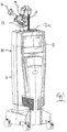
- the medical laser unit comprises a base unit 11 and an adaptor 12, which will be described hereafter in more detail.
- the base unit 11 comprises a main laser source (not shown), in the present example comprising a CO 2 laser, to generate a main laser beam with an output wavelength of 10.6 ⁇ m.
- a main laser source (not shown)
- a main guide laser (not shown) is also mounted in the base unit 11 to produce a visual main guide beam.
- Suitable beam combination and collimation optics are provided such that the base unit 11 outputs a main beam comprising the 10.6 ⁇ m beam and the main guide beam such that both beams are collimated and co-propagating.
- the base unit 11 further comprises a control unit shown in dashed outline at 13 and a control screen 13a which is operable to display operating information received from a control unit and to receive operator input to the control unit to control the laser output of the medical laser unit 10.
- the main beam and main guide beam are transmitted to the adaptor 12.
- the adaptor 12 has a first output port 14, for connection to a hollow waveguide, and a second output port 15 for connection to an internally reflective articulated arm 16.
- the adaptor 12 has a switching element, described below, which is controllable by the control unit 13 to direct the received main beam to one of the first output port 14 and second output port 15 as directed by an operator.
- control unit 13 may be connected to the control unit 13 such that they operate as a single controller, preferably in a manner transparent to the operator.
- the adaptor 12 will now be described in more detail with reference to figures 2 to 8 .
- the adaptor 12 comprises an opto-mechanical chassis generally shown at 20. This is a solid, rigid body which serves as a reference surface with fixed location stops onto which other components can be mounted.
- the opto-mechanical chassis comprises a main body 21 with a number of ports and recesses defined therein.
- the main body 21 is milled from aluminium to provide suitable rigidity, coefficient of thermal expansion and robustness.
- the surfaces are also finished, for example by anodising, to produce a protective surface which has a matt texture to diffuse potentially hazardous laser reflections.
- input beam path 22 extends vertically from a lower part of the body 21.
- First output beam path 23 and second output beam path 24 lead to the first output port 14and second output port 15 respectively.
- First output beam path 23 is co-planar with the input beam path 22 and second output beam path 24, and is inclined at an oblique angle relative to the input beam path 22.
- the second output beam path 24 is co-linear with input beam path 22.
- the rigid body 21 has an output support part best shown at 25, which has a third output beam path 26 extending therethrough which is co-linear with the first output beam path 24.
- the support part 25 has an inclined connection face 27 which is perpendicular to the third output beam path 26 and provided with mounting points 28.
- Channel 29 extends in a linear manner into the main body 21 and has an angled inner face 30.
- Input beam path 22 and first beam path 23 have respective openings 22a, 23a in the angled surface 30, and the input, first and second beam paths 22, 23, 24 converge at point A within channel 29.
- the opto-mechanical chassis 21 comprises an auxiliary guide laser support 31 extending alongside the support part 25.
- the support part 25 has an inclined rear surface 32 to support an auxiliary guide beam combiner as discussed in more detail below and a transversely extending auxiliary guide beam path 32a extending towards a corresponding board in the auxiliary guide beam support arm 31.
- connection points 34 for connection to a beam combiner comprising the second output port 15 to direct the beam to an articulated arm 16.
- the opto-mechanical chassis 20 further comprises a vertical support 40, on which the main body 21 is supported.
- the vertical support 40 comprises a generally cylindrical body 41 defining an input beam port.
- An upper flange 42 engages a lower surface 35 of the body 21 and comprises a plurality of apertures 43 through which bolts 44 may pass to be received in threaded apertures (not shown) in the body 21.
- the vertical support 40 comprises an outwardly extending flange 45 with apertures 46 therein to enable the vertical support 40 to be connected to an optical bench surface 47 provided at the upper surface of the base unit 11.
- the control switch comprises a mirror mount 51 best shown in Fig. 9 which has a vertical support plate 52.
- the vertical support plate 52 comprises a mirror support arm 53 which is dimensioned to be received in channel 29.
- a mirror support plate 54 which is inclined relative to the vertical support plate 52.
- the mirror support plate 54 has a circular aperture 55 in which is received a plane mirror 56, the reflective surface of the mirror being directed downwardly and to the left as shown in Fig. 9 .
- a plane mirror it will be apparent that a curved mirror may be used if desirable, for example for focussing or beam conditioning purposes.
- aperture 55 has an inwardly directed lip 57.
- Three recesses 58 are located within the lip 57 which receive bearing balls 59, the bearing balls 59 defining a correctly aligned surface.
- the mirror 56 when in position is supported by these bearing balls 59.
- a retaining ring 60 is held in place by screws 61 against the back of the mirror 56.
- the opto-mechanical chassis 20 is provided with horizontally extending guide rails 70, 71 disposed above and below the channel 29.
- Fig. 10 shows lower guide rail 71 in position and upper guide rail 70 in the correct orientation for connection to the chassis 20.
- Upper guide block 70a is slidably mounted on the upper guide rail 70
- lower guide blocks 71a, 71a are slidably mounted on the lower guide rail 71.
- Vertical support plate 51 is connected to the guide blocks 70a, 71a, 71b such that the mirror assembly 50 is moveable lengthways of the channel 29.
- a linear actuator comprising a stepper motor 72 connected to a threaded rod 73 extending through a suitable threaded nut 77.
- Driving the stepper motor 72 causes the rod 73 to rotate and hence causes linear movement of the nut 77 and mirror assembly 50.
- the connection between the mirror assembly 50 and nut 77 preferably comprises a spring or flexible element to provide a degree of freedom between the mount and actuator.
- each step of the stepper motor moves the mirror assembly by 13 ⁇ m.
- Screw 76 has a distal ball end located to provide an end stop for the mirror assembly 50.
- the mirror assembly 50 is thus movable by the linear actuator between first and second positions.
- the mirror 56 extends between the input beam path 22 and second input beam path 24, such that the main beam is reflected into first beam path 23.
- the mirror surface passes through point A in Fig.4 .
- the mirror assembly is offset from the beam paths 22, 23, 24 such that the main passes from the input beam path 22 to the second output beam path 24.
- optical sensors 74, 75 are provided to confirm when the mirror assembly 50 is in the first position or second position.
- Fig. 11 is a perspective view of the opto-mechanical chassis 21 showing the output port 14 and the auxiliary guide beam support 31.
- the first output port 14 comprises a cylindrical element 80 with a flange 81 at one end which is connected to the angled surface 27 of the opto-mechanical chassis 21 by bolts 81a received in threaded bores 28.
- a wave guide connection port 82 is mounted at the opposite end, protected by a lid 83.
- the auxiliary guide beam source is shown at 84 comprising a red laser diode with its associated electronics mounted in a single element.
- the auxiliary guide beam beam 84 is mounted on a support plate 85 which is adjustably connected to the support 31 by adjustable bolts 86.
- the auxiliary guide beam source 84 is directed at a beam combiner comprising an angled mirror 88 supported at the inclined rear surface 32 such that it is set at approximately 45° to the cylindrical part 80 and the auxiliary guide beam source 84.
- the angled mirror 88 is positioned such that the aiming beam is directed into the first output port 14 and the main laser beam, when directed through first output beam path 24, passes through the mirror 88 substantially undeflected and into third output beam path 26. It will be apparent that the beam acts to combine the main laser beam and auxiliary guide beam when the first output port 14 is in use.
- the flexible wave guide 90 has a hollow core 91 within a silica substrate 92.
- the inner surfaces of the silicate substrate 92 are coated with a reflective surface 93, in the present example an interface film of silver deposited on the inner surface of the silicate substrate, and then a silver iodide coat deposited on the silver interface film.
- the silica substrate 92 is surrounded by a protective polymer coating 94.
- a guide beam is provided by directing the auxiliary guide beam into the silica substrate 92.
- the bolts 86 are adjusted such that the aiming beam is offset from the main beam as illustrated in Fig. 14a .
- the end of the flexible wave guide is held in a connector 95, and the beams are aligned in such that the main beam 96 is directed into the hollow core 91 and the auxiliary guide beam 97 is offset from the main beam 96 and enters the silica substrate 92.
- the alignment can be carried using an apparatus such as that shown in Fig.
- a dummy fibre holder 98 having the same dimensions as the waveguide holder 95.
- a conventional optical fibre 99 is held within the dummy fibre holder 98 such that the end 99a of the fibre 99 is at the same offset position as the silica cladding 92 of the flexible wave guide 90.
- a photodetector 100 is used to measure the light coupled into the alignment fibre 99. Accordingly, the bolts 86 can be adjusted to vary the direction of the auxiliary guide beam 97 to maximise the signal at the photodetector unit 100 to confirm that the auxiliary guide beam is correctly aligned.
- a cooling fluid system is provided, in the present example a pneumatic cooling air system.
- a suitable cooling system is shown diagrammatically in Fig. 12 .
- the base unit is diagrammatically illustrated at 11 and a pneumatic control apparatus is shown at 110.
- a distributor is shown at 111 which can receive pressurized from an internal compressor 112 provided within the base unit 11, or from an external source 113, which may be an external tank or an external pneumatic supply system.
- the distributor 111 is under the control of the control unit in the base unit 11.
- a first pneumatic connection 114 leads from the distributor 111 to an air chamber 115 located in flow communication with the wave guide connection part 82.
- a second pneumatic connection 116 is connectible to external flexible air tubes shown diagrammatically at 117 which extend along an outside surface of the articulated arm 16 and direct air towards an accessory or control element at the distal end of the articulated arm 16, for example to be connected to an air inlet of the accessory.
- the supply of cooling fluid amongst other advantages helps to cool the flexible wave guide, when working at high energies, and also blows smoke or debris away from the operating point of the laser. Where a higher air flow is required, particularly for using a flexible wave guide at high energies, the internal compressor 112 may not be sufficient and the connection to an external source 113 is desirable.
- suitably filtered and dry compressed air is used, it will be apparent that any other suitable gas or gas mixture may be used.
- a medical laser unit 10 may be adapted by removing pre-existing articulated arm or flexible wave guide connection, and attaching an adaptor 15 to an optical bench part of the base unit 11 as described herein.
- the method of adapting the medical laser unit may also include connecting the optical wave guide connector part 82 to the control unit, and connecting the auxiliary guide beam laser 80 to the control unit.
- the actuator is similarly connected to the control unit.
- the adaptor 15 is provided with a dedicated controller 120 mounted on the optical chassis 21, and the auxiliary controller 120 is operable to transmit and receive information to the controller, and control the linear actuator and auxiliary guide beam laser in response to instructions from the controller.
- the pneumatic distributor 111 may be controlled by the auxiliary controller 120 or entirely controlled by the main controller.
- the controller may detect the presence of an optical wave guide, or be informed of the presence of the optical wave guide by the auxiliary controller 120 and present options to the operator on the screen. If the operator selects the flexible wave guide, then the auxiliary guide beam laser is actuated, and the actuator is operated to move the switching apparatus to the first position.
- the main laser beam is directed to the first output port 14 and into the flexible wave guide, and the auxiliary guide beam is directed into the silica substrate of the flexible wave guide as discussed herein.
- the pneumatic distributor 111 is operated to supply air under pressure through the flexible wave guide as discussed above.
- the linear actuator is operated to move the mirror assembly to the second position. In this position, the main laser beam and the guide beam are unobstructed and pass through the input beam path, second beam path and are reflected within the articulated arm.
- the pneumatic distributor is operated to supply pressurized air to the articulated arm connection.
- the auxiliary guide beam laser is not activated as the auxiliary guide beam is not required.
- a medical laser unit may be provided as a new unit with an adaptor 12 already installed. If so, it will be apparent that auxiliary controller 120 may be omitted and the linear actuator, auxiliary guide beam laser and flexible wave guide detector may be directly connectible to and operated by the main control unit. When a medical laser unit is modified to have an adaptor 12, the software in the main control unit may be updated accordingly.
Landscapes
- Physics & Mathematics (AREA)
- Health & Medical Sciences (AREA)
- Optics & Photonics (AREA)
- Surgery (AREA)
- Life Sciences & Earth Sciences (AREA)
- General Physics & Mathematics (AREA)
- Biomedical Technology (AREA)
- Molecular Biology (AREA)
- Nuclear Medicine, Radiotherapy & Molecular Imaging (AREA)
- Engineering & Computer Science (AREA)
- Electromagnetism (AREA)
- Heart & Thoracic Surgery (AREA)
- Medical Informatics (AREA)
- Otolaryngology (AREA)
- Animal Behavior & Ethology (AREA)
- General Health & Medical Sciences (AREA)
- Public Health (AREA)
- Veterinary Medicine (AREA)
- Laser Surgery Devices (AREA)
- Radiation-Therapy Devices (AREA)
- Lasers (AREA)
Description
- This invention relates to an adaptor for a medical laser unit, a medical laser unit, a method of adapting a base unit for a medical laser unit, a control unit for a medical laser unit and a method of operating a medical laser unit.
- Lasers have found a number of applications in medical procedures. Using suitably focussed and powerful laser beams, tissues can be excised, ablated or cut with fine control and with reduced bleeding. Example treatments are excision and vaporisation of benign and cancerous growths and fibromas, and aesthetic treatments. Conventionally, a CO2 laser is used as the source of the beam producing light at a wavelength of 10.6 µm. Because this wavelength is not suitable for transmission through conventional optical fibres, where it would be absorbed by the silica, it is known to use either hollow flexible waveguides, or internally reflective articulated arms, to direct the beam to the site of operation. Adaptors or switching apparatus that connect a base medical laser unit to a plurality of output devices and which comprise switching devices for controlling the travel path of the laser beam and one or more guiding beams are known from the state of the art, for example as described in
US 4 550 240 A ,EP 0093 005 A2 orFR 2 570 509EP 2 169 435 A2US 2012/321259 to use hollow flexible waveguides to guide a main laser beam and a guide beam at the same time whereby the guide beam can be guided through optical fibers which are embedded in the cladding of the hollow wave guide. - According to a first aspect of the invention there is provided a dual port switching apparatus and a flexible waveguide, the flexible wave guide (90) having a hollow core (91) within a silica substrate (92) whereby the inner surfaces of the silica substrate (92) is coated with a reflective surface (93); the switching adaptor comprising a connection part for mounting to a base unit, an input beam port to receive a main laser beam from a base unit, a first output port for connection to a flexible wave guide, a second output port for connection to an articulated arm, and a switching element moveable between a first position and a second position to direct an input beam to one of the first output port and the second output port. The adaptor further comprises an auxiliary guide beam source, and a beam combiner to direct an auxiliary guide beam to the first output port. The invention is characterized in that the auxiliary guide beam source is actuated if a flexible waveguide is selected by a user and the auxiliary guide beam is controllable to be directed into the silica substrate of the hollow wave guide.
- The switching element may comprise a mirror.
- The mirror may be moveable in a linear direction between the first position and the second position.
- The adaptor may comprise a linear actuator operable to move the switching element between the first position and the second position.
- The input beam port may define an input beam path extending generally vertically, one of the first and second output ports may extend substantially vertically in line with the input beam path, and the other of the first output port and second output port may extend at an angle relative to the input beam path.
- In one of the first position and of the second position the switching element may extends into the input beam path, and in the other of the first position and second position, may be spaced from the input beam path.
- The adaptor may comprise a pressurized gas connection to allow supply of pressurized gas to the first output port.
- According to a second aspect of the invention there is provided a medical laser unit comprising a base unit, the base unit comprising a main laser source and a base unit output port, and an adaptor according to the first aspect of the invention, the adaptor being mounted on the base unit such that the input beam port is connected to the base output beam port to receive the main beam from the main laser source.
- The main laser source may comprise a CO2 laser to provide the main beam.
- The base unit may comprise a main guide beam source and alignment optics wherein the main laser guide beam may be aligned with the CO2 laser beam.
- The apparatus may comprise a control unit operable to control the main laser source.
- The medical laser unit may have a user input device to receive user instructions and transmit instructions to the control unit.
- The control unit is may be operable to control the switching element.
- The medical laser unit may be operable to detect if a flexible wave guide is connected to the first output port.
- If a flexible wave guide is detected, the control unit may be operable to control the switching element to direct the COs laser beam to the first output port, and control the auxiliary guide beam source.
- The medical laser unit may comprised a pressurised gas source and a pressurised gas controller, the control unit being operable to control the pressurised gas controller to direct cooling fluid to one of the first output port and an articulated arm.
- There is provided a method of adapting a medical laser apparatus, the medical laser apparatus being a base unit comprising a main laser source and a laser output port, the method comprising the step of providing an adaptor according to the first aspect of the invention, and mounting the adaptor on the base unit such that the input beam port is aligned with the laser beam port.
- Where the base unit comprises a control unit, the method may comprise the step of connecting the control unit to the switching element such that the control unit is operable to move the switching element between the first position and the second position.
- The method may comprise the step of connecting the control unit to the auxiliary guide beam source such that the control unit is operable to control the auxiliary guide beam.
- There is provided a control unit for a medical laser unit comprising a main laser to generate a main beam, the medical laser unit having an adaptor comprising a first output port, a second output port and a switching element, the control unit being operable to receive an operator input and move the switching element between a first position in which the main beam is directed to the first output port and a second position in which the main beam is directed to the second output port.
- There is provided a method of operating a medical laser unit comprising operating a main laser to generate a main beam, and operating a switching element to move the switching element between a first position in which the main beam is directed to a first output port and a second position in which the main beam is directed to a second output port.
- An embodiment of the invention is described by way of example only with reference to the accompanying drawings wherein;
-
Fig. 1 is a perspective view of a medical laser unit, -
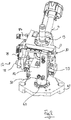
Fig. 2 is a perspective view of an adaptor unit for the apparatus ofFig. 1 , -
Fig. 3 is a perspective view of the adaptor ofFig. 2 with some elements removed, -
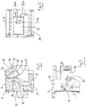
Fig. 4 is a section on line 4-4 ofFig. 3 , -
Fig. 5 is a view indirection 5 of part of the adaptor ofFig. 3 , -
Fig. 6 is a plan view of the adaptor ofFig. 3 , -
Fig.7 is a exploded perspective of a support part of the adaptor ofFig.3 , -
Fig. 8 is a cross-sectional view of the adaptor ofFig. 7 , -
Fig. 9 is a perspective view on a larger scale of part of a switching apparatus for use in the adaptor ofFig. 3 , -
Fig. 10 is a partly exploded perspective view from above of the adaptor ofFig. 3 showing guide rails for the switching apparatus ofFig. 9 , -
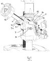
Fig. 11 is a perspective view of part of the adaptor ofFig. 2 , -
Fig. 12 is a partly transparent perspective view of part of the adaptor ofFig. 2 , -
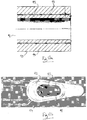
Fig. 13a is a section through a flexible wave guide, -
Fig. 13b is a partially cut away perspective view of the wave guide ofFig. 13a , -
Fig. 14a is a section through the first output port of the apparatus ofFig. 2 , -
Fig. 14b is a section through an alignment apparatus for the first output port ofFig. 14a , and -
Fig. 15 is a diametrical illustration of a cooling fluid system to use with the apparatus ofFig. 1 . - With specific reference now to the drawings in detail, it is stressed that the particulars shown are by way of example and for purposes of illustrative discussion of the preferred embodiments of the present invention only, and are presented in the cause of providing what is believed to be the most useful and readily understood description of the principles and conceptual aspects of the invention. In this regard, no attempt is made to show structural details of the invention in more detail than is necessary for a fundamental understanding of the invention, the description taken with the drawings making apparent to those skilled in the art how the several forms of the invention may be embodied in practice.
- Before explaining at least one embodiment of the invention in detail, it is to be understood that the invention is not limited in its application to the details of construction and the arrangement of the components set forth in the following description or illustrated n the drawings. The invention is applicable to other embodiments or of being practiced or carried out in various ways. Also, it is to be understood that the phraseology and terminology employed herein is for the purpose of description and should not be regarded as limiting.
- Referring now to
Fig. 1 , a medical laser unit generally embodying the invention is shown at 10. The medical laser unit comprises a base unit 11 and anadaptor 12, which will be described hereafter in more detail. The base unit 11 comprises a main laser source (not shown), in the present example comprising a CO2 laser, to generate a main laser beam with an output wavelength of 10.6 µm. As the main laser beam is in the infrared and so is not visible, a main guide laser (not shown) is also mounted in the base unit 11 to produce a visual main guide beam. Suitable beam combination and collimation optics are provided such that the base unit 11 outputs a main beam comprising the 10.6 µm beam and the main guide beam such that both beams are collimated and co-propagating. The base unit 11 further comprises a control unit shown in dashed outline at 13 and a control screen 13a which is operable to display operating information received from a control unit and to receive operator input to the control unit to control the laser output of the medical laser unit 10. The main beam and main guide beam are transmitted to theadaptor 12. Theadaptor 12 has afirst output port 14, for connection to a hollow waveguide, and asecond output port 15 for connection to an internally reflective articulatedarm 16. Theadaptor 12 has a switching element, described below, which is controllable by the control unit 13 to direct the received main beam to one of thefirst output port 14 andsecond output port 15 as directed by an operator. Although not shown, it will be apparent that electrical connections are provided between the control unit 13 and the functional elements of theadaptor 12 so that the operation of theadaptor 12 can be monitored and controlled as appropriate. Where theadaptor 12 has a separate auxiliary control unit, this may be connected to the control unit 13 such that they operate as a single controller, preferably in a manner transparent to the operator. - The
adaptor 12 will now be described in more detail with reference tofigures 2 to 8 . Theadaptor 12 comprises an opto-mechanical chassis generally shown at 20. This is a solid, rigid body which serves as a reference surface with fixed location stops onto which other components can be mounted. - As seen in
Fig. 4 to Fig. 6 , the opto-mechanical chassis comprises amain body 21 with a number of ports and recesses defined therein. Themain body 21 is milled from aluminium to provide suitable rigidity, coefficient of thermal expansion and robustness. Preferably, the surfaces are also finished, for example by anodising, to produce a protective surface which has a matt texture to diffuse potentially hazardous laser reflections. - Within the
main body 21,input beam path 22 extends vertically from a lower part of thebody 21. First output beam path 23 and secondoutput beam path 24 lead to the first output port 14andsecond output port 15 respectively. First output beam path 23 is co-planar with theinput beam path 22 and secondoutput beam path 24, and is inclined at an oblique angle relative to theinput beam path 22. The secondoutput beam path 24 is co-linear withinput beam path 22. Therigid body 21 has an output support part best shown at 25, which has a thirdoutput beam path 26 extending therethrough which is co-linear with the firstoutput beam path 24. The support part 25 has an inclined connection face 27 which is perpendicular to the thirdoutput beam path 26 and provided with mountingpoints 28. -
Channel 29 extends in a linear manner into themain body 21 and has an angledinner face 30.Input beam path 22 and first beam path 23 have respective openings 22a, 23a in theangled surface 30, and the input, first andsecond beam paths channel 29. - To provide for an auxiliary guide beam as discussed in more detail below, the opto-
mechanical chassis 21 comprises an auxiliaryguide laser support 31 extending alongside the support part 25. The support part 25 has an inclinedrear surface 32 to support an auxiliary guide beam combiner as discussed in more detail below and a transversely extending auxiliary guide beam path 32a extending towards a corresponding board in the auxiliary guidebeam support arm 31. - At an
upper surface 33 thereof, themain body 21 is provided with connection points 34 for connection to a beam combiner comprising thesecond output port 15 to direct the beam to an articulatedarm 16. - The opto-
mechanical chassis 20 further comprises avertical support 40, on which themain body 21 is supported. In this example thevertical support 40 comprises a generally cylindrical body 41 defining an input beam port. Anupper flange 42 engages alower surface 35 of thebody 21 and comprises a plurality of apertures 43 through whichbolts 44 may pass to be received in threaded apertures (not shown) in thebody 21. At the lower end thevertical support 40 comprises an outwardly extending flange 45 with apertures 46 therein to enable thevertical support 40 to be connected to an optical bench surface 47 provided at the upper surface of the base unit 11. - To switch the main beam, a switching apparatus or mirror assembly is shown generally indicated at 50. The control switch comprises a mirror mount 51 best shown in
Fig. 9 which has avertical support plate 52. Thevertical support plate 52 comprises amirror support arm 53 which is dimensioned to be received inchannel 29. At the end ofsupport arm 53 there is provided amirror support plate 54 which is inclined relative to thevertical support plate 52. Themirror support plate 54 has a circular aperture 55 in which is received a plane mirror 56, the reflective surface of the mirror being directed downwardly and to the left as shown inFig. 9 . Although the present embodiment uses a plane mirror, it will be apparent that a curved mirror may be used if desirable, for example for focussing or beam conditioning purposes. - To support the mirror 56, aperture 55 has an inwardly directed lip 57. Three recesses 58 are located within the lip 57 which receive
bearing balls 59, the bearingballs 59 defining a correctly aligned surface. The mirror 56 when in position is supported by these bearingballs 59. A retaining ring 60 is held in place by screws 61 against the back of the mirror 56. - To provide for sliding movement of the
mirror assembly 50, the opto-mechanical chassis 20 is provided with horizontally extendingguide rails 70, 71 disposed above and below thechannel 29.Fig. 10 shows lower guide rail 71 in position andupper guide rail 70 in the correct orientation for connection to thechassis 20. Upper guide block 70a is slidably mounted on theupper guide rail 70, and lower guide blocks 71a, 71a are slidably mounted on the lower guide rail 71. Vertical support plate 51 is connected to the guide blocks 70a, 71a, 71b such that themirror assembly 50 is moveable lengthways of thechannel 29. - To provide for controlled sliding movement of the
mirror assembly 50, in the present example a linear actuator is provided comprising astepper motor 72 connected to a threadedrod 73 extending through a suitable threaded nut 77. Driving thestepper motor 72 causes therod 73 to rotate and hence causes linear movement of the nut 77 and mirror assembly 50.To avoid motor cleaving or motor sticking, the connection between themirror assembly 50 and nut 77 preferably comprises a spring or flexible element to provide a degree of freedom between the mount and actuator. In the present example, each step of the stepper motor moves the mirror assembly by 13µm.Screw 76 has a distal ball end located to provide an end stop for themirror assembly 50. - The
mirror assembly 50 is thus movable by the linear actuator between first and second positions. In the first position, the mirror 56 extends between theinput beam path 22 and secondinput beam path 24, such that the main beam is reflected into first beam path 23. Ideally, the mirror surface passes through point A inFig.4 . In the second position, the mirror assembly is offset from thebeam paths input beam path 22 to the secondoutput beam path 24. - To provide for detection of the position of the
mirror assembly 50,optical sensors 74, 75 are provided to confirm when themirror assembly 50 is in the first position or second position. - The
first output port 14 for connection to a flexible wave guide and the auxiliary aiming beam will now be discussed with reference tofigures 11 to 14 .Fig. 11 is a perspective view of the opto-mechanical chassis 21 showing theoutput port 14 and the auxiliaryguide beam support 31. As seen inFig. 11 , thefirst output port 14 comprises acylindrical element 80 with a flange 81 at one end which is connected to the angled surface 27 of the opto-mechanical chassis 21 by bolts 81a received in threaded bores 28. A wave guide connection port 82 is mounted at the opposite end, protected by a lid 83. The auxiliary guide beam source is shown at 84 comprising a red laser diode with its associated electronics mounted in a single element. The auxiliaryguide beam beam 84 is mounted on a support plate 85 which is adjustably connected to thesupport 31 byadjustable bolts 86. As shown inFig. 12 , the auxiliaryguide beam source 84 is directed at a beam combiner comprising anangled mirror 88 supported at the inclinedrear surface 32 such that it is set at approximately 45° to thecylindrical part 80 and the auxiliaryguide beam source 84.. Theangled mirror 88 is positioned such that the aiming beam is directed into thefirst output port 14 and the main laser beam, when directed through firstoutput beam path 24, passes through themirror 88 substantially undeflected and into thirdoutput beam path 26. It will be apparent that the beam acts to combine the main laser beam and auxiliary guide beam when thefirst output port 14 is in use. - An end part of a flexible wave guide as used herein is shown in 90 in
Fig. 13a and Fig. 13b . Theflexible wave guide 90 has a hollow core 91 within asilica substrate 92. The inner surfaces of thesilicate substrate 92 are coated with areflective surface 93, in the present example an interface film of silver deposited on the inner surface of the silicate substrate, and then a silver iodide coat deposited on the silver interface film. Thesilica substrate 92 is surrounded by aprotective polymer coating 94. - As the auxiliary guide beam will not be reliably propagated down the hollow core 91, in the present example a guide beam is provided by directing the auxiliary guide beam into the
silica substrate 92. Thebolts 86 are adjusted such that the aiming beam is offset from the main beam as illustrated inFig. 14a . Referring toFig. 14a the end of the flexible wave guide is held in aconnector 95, and the beams are aligned in such that the main beam 96 is directed into the hollow core 91 and theauxiliary guide beam 97 is offset from the main beam 96 and enters thesilica substrate 92. The alignment can be carried using an apparatus such as that shown inFig. 14b , where adummy fibre holder 98 is used having the same dimensions as thewaveguide holder 95. A conventional optical fibre 99 is held within thedummy fibre holder 98 such that the end 99a of the fibre 99 is at the same offset position as thesilica cladding 92 of theflexible wave guide 90. Aphotodetector 100 is used to measure the light coupled into the alignment fibre 99. Accordingly, thebolts 86 can be adjusted to vary the direction of theauxiliary guide beam 97 to maximise the signal at thephotodetector unit 100 to confirm that the auxiliary guide beam is correctly aligned. - To provide cooling, a cooling fluid system is provided, in the present example a pneumatic cooling air system. A suitable cooling system is shown diagrammatically in
Fig. 12 . The base unit is diagrammatically illustrated at 11 and a pneumatic control apparatus is shown at 110. A distributor is shown at 111 which can receive pressurized from aninternal compressor 112 provided within the base unit 11, or from anexternal source 113, which may be an external tank or an external pneumatic supply system. The distributor 111 is under the control of the control unit in the base unit 11. A first pneumatic connection 114 leads from the distributor 111 to an air chamber 115 located in flow communication with the wave guide connection part 82. A second pneumatic connection 116 is connectible to external flexible air tubes shown diagrammatically at 117 which extend along an outside surface of the articulatedarm 16 and direct air towards an accessory or control element at the distal end of the articulatedarm 16, for example to be connected to an air inlet of the accessory. The supply of cooling fluid amongst other advantages helps to cool the flexible wave guide, when working at high energies, and also blows smoke or debris away from the operating point of the laser. Where a higher air flow is required, particularly for using a flexible wave guide at high energies, theinternal compressor 112 may not be sufficient and the connection to anexternal source 113 is desirable. Although in the present example suitably filtered and dry compressed air is used, it will be apparent that any other suitable gas or gas mixture may be used. - The present invention is particularly advantageous in that it permits an existing medical laser unit 10 to be retrofitted with an
adaptor 15 to provide more flexible operation. Accordingly, a medical laser unit 10 may be adapted by removing pre-existing articulated arm or flexible wave guide connection, and attaching anadaptor 15 to an optical bench part of the base unit 11 as described herein. The method of adapting the medical laser unit may also include connecting the optical wave guide connector part 82 to the control unit, and connecting the auxiliaryguide beam laser 80 to the control unit. The actuator is similarly connected to the control unit. In the present example, theadaptor 15 is provided with a dedicated controller 120 mounted on theoptical chassis 21, and the auxiliary controller 120 is operable to transmit and receive information to the controller, and control the linear actuator and auxiliary guide beam laser in response to instructions from the controller. Similarly, the pneumatic distributor 111 may be controlled by the auxiliary controller 120 or entirely controlled by the main controller. In operation, the controller may detect the presence of an optical wave guide, or be informed of the presence of the optical wave guide by the auxiliary controller 120 and present options to the operator on the screen. If the operator selects the flexible wave guide, then the auxiliary guide beam laser is actuated, and the actuator is operated to move the switching apparatus to the first position. In the first position, the main laser beam is directed to thefirst output port 14 and into the flexible wave guide, and the auxiliary guide beam is directed into the silica substrate of the flexible wave guide as discussed herein. The pneumatic distributor 111 is operated to supply air under pressure through the flexible wave guide as discussed above. - Similarly, if the operator selects the articulated arm, the linear actuator is operated to move the mirror assembly to the second position. In this position, the main laser beam and the guide beam are unobstructed and pass through the input beam path, second beam path and are reflected within the articulated arm. Similarly, the pneumatic distributor is operated to supply pressurized air to the articulated arm connection. The auxiliary guide beam laser is not activated as the auxiliary guide beam is not required.
- In the alternative, it will be apparent that a medical laser unit may be provided as a new unit with an
adaptor 12 already installed. If so, it will be apparent that auxiliary controller 120 may be omitted and the linear actuator, auxiliary guide beam laser and flexible wave guide detector may be directly connectible to and operated by the main control unit. When a medical laser unit is modified to have anadaptor 12, the software in the main control unit may be updated accordingly. - In the above description, an embodiment is an example or implementation of the invention. The various appearances of "one embodiment", "an embodiment" or "some embodiments" do not necessarily all refer to the same embodiments.
- Although various features of the invention may be described in the context of a single embodiment, the features may also be provided separately or in any suitable combination. Conversely, although the invention may be described herein in the context of separate embodiments for clarity, the invention may also be implemented in a single embodiment.
- Furthermore, it is to be understood that the invention can be carried out or practiced in various ways and that the invention can be implemented in embodiments other than the ones outlined in the description above.
- Meanings of technical and scientific terms used herein are to be commonly understood as by one of ordinary skill in the art to which the invention belong, unless otherwise defined.
Claims (16)
- A dual port switching adaptor (12) and a flexible waveguide, the flexible wave guide (90) having a hollow core (91) within a silica substrate (92) whereby the inner surfaces of the silica substrate (92) is coated with a reflective surface (93); the switching adaptor (12) comprising a connection part for mounting to a base unit (11),
an input beam port to receive a main laser beam from a base unit (11),
a first output port (14) detachably connected to a flexible hollow wave guide for directing a main beam (96) into the hollow core (91) of the flexible waveguide,
a second output port (15) for connection to an articulated arm (16)and for directing the main beam to an articulated arm (16), and
a switching element (56) moveable between a first position and a second position to direct an input beam to one of the first output port (14) or the second output port (15), the adaptor (12) further comprising an auxiliary guide beam source (84), and a beam combiner to direct an auxiliary guide beam to the first output port characterized in the auxiliary guide beam (97) being controllable to be directed into the silica substrate (92) of the hollow wave guide. - An adaptor (12) and a flexible hollow waveguide according to claim 1, wherein the switching element (56) comprises a mirror.
- An adaptor (12) and a flexible hollow waveguide according to claim 2, wherein the mirror is moveable in a linear direction between the first position and the second position.
- An adaptor (12) and a flexible hollow waveguide according to claim 3 comprising a linear actuator operable to move the switching element between the first position and the second position.
- An adaptor (12) and a flexible hollow waveguide according to any one of the preceding claims where the auxiliary guide beam is adjustable to direct the auxiliary guide beam (97) into a cladding layer of the hollow wave guide.
- An adaptor (12) and a flexible hollow waveguide according to any one of the preceding claims wherein the input beam port defines an input beam path extending generally vertically, and wherein one of the first and second output ports (14, 15) extend substantially vertically in line with the input beam path, and the other of the first output port and second output port extend at an angle relative to the input beam path.
- An adaptor (12) and a flexible hollow waveguide according to claim 6 wherein, in one of the first position and of the second position the switching element extends into the input beam path, and in the other of the first position and second position, is spaced from the input beam path.
- An adaptor (12) and a flexible hollow waveguide according to any one of the preceding claims comprising a cooling fluid connection to supply cooling fluid to the first output port.
- A medical laser unit (10) comprising a base unit (11), the base unit comprising a laser source and a base unit output port, and an adaptor (12) and a flexible hollow waveguide according to any one of the preceding claims, the adaptor being mounted on the base unit (11) such that the input beam port is connected to the base output beam port to receive the main beam from the main laser source, the base unit comprises a main guide beam source and alignment optics wherein the main guide beam is aligned with the main beam.
- A medical laser unit (10) according to claim 9, wherein the main laser source comprises a CO2 laser to provide the main beam.
- A medical laser unit (10) according to claim 9 or claim 10, comprising a control unit (13) operable to control the main laser source.
- A medical laser unit (10) according to claim 11 having a user input device to receive user instructions and transmit instructions to the control unit (13).
- A medical laser apparatus according to claim 11 or claim 12 wherein the control unit (13) is operable to control the switching element (56).
- A medical laser unit according to any one of claims 9 to 13 operable to detect if a flexible wave guide is connected to the first output port (14).
- A medical laser apparatus according to claim 14 when dependent on claim 10 wherein, if a flexible wave guide is detected, the control unit (13) is operable to; control the switching element (56) to direct the C02 laser beam to the first output port (14), and control the auxiliary guide beam source.
- A medical laser unit according to any one of claims 9 to 15 comprising a pressurised gas source and a pressurised gas controller, the control unit being operable to control the pressurized gas controller to direct cooling fluid to one of the first output port (14)and an articulated arm (16) .
Priority Applications (1)
| Application Number | Priority Date | Filing Date | Title |
|---|---|---|---|
| EP19179392.6A EP3605173B1 (en) | 2013-04-15 | 2014-04-14 | Adapter for connecting a medical laser to a flexible waveguide or an articulated arm |
Applications Claiming Priority (2)
| Application Number | Priority Date | Filing Date | Title |
|---|---|---|---|
| GB1306832.5A GB2513123B (en) | 2013-04-15 | 2013-04-15 | Adaptor |
| PCT/IB2014/060704 WO2014170815A1 (en) | 2013-04-15 | 2014-04-14 | Adapter for connecting a medical laser to a flexible waveguide or an articulated arm |
Related Child Applications (1)
| Application Number | Title | Priority Date | Filing Date |
|---|---|---|---|
| EP19179392.6A Division EP3605173B1 (en) | 2013-04-15 | 2014-04-14 | Adapter for connecting a medical laser to a flexible waveguide or an articulated arm |
Publications (2)
| Publication Number | Publication Date |
|---|---|
| EP2987012A1 EP2987012A1 (en) | 2016-02-24 |
| EP2987012B1 true EP2987012B1 (en) | 2019-06-12 |
Family
ID=48537279
Family Applications (2)
| Application Number | Title | Priority Date | Filing Date |
|---|---|---|---|
| EP19179392.6A Active EP3605173B1 (en) | 2013-04-15 | 2014-04-14 | Adapter for connecting a medical laser to a flexible waveguide or an articulated arm |
| EP14722361.4A Active EP2987012B1 (en) | 2013-04-15 | 2014-04-14 | Adapter for connecting a medical laser to a flexible waveguide or an articulated arm |
Family Applications Before (1)
| Application Number | Title | Priority Date | Filing Date |
|---|---|---|---|
| EP19179392.6A Active EP3605173B1 (en) | 2013-04-15 | 2014-04-14 | Adapter for connecting a medical laser to a flexible waveguide or an articulated arm |
Country Status (6)
| Country | Link |
|---|---|
| US (4) | US10746936B2 (en) |
| EP (2) | EP3605173B1 (en) |
| CN (2) | CN105143939B (en) |
| GB (1) | GB2513123B (en) |
| IL (3) | IL300941B2 (en) |
| WO (1) | WO2014170815A1 (en) |
Families Citing this family (4)
| Publication number | Priority date | Publication date | Assignee | Title |
|---|---|---|---|---|
| GB2513123B (en) * | 2013-04-15 | 2015-12-02 | Lumenis Ltd | Adaptor |
| US10175445B2 (en) | 2014-10-20 | 2019-01-08 | Lumenis Ltd. | Apparatus and method for aligning light beams |
| ES2946276T3 (en) * | 2017-12-12 | 2023-07-14 | Alcon Inc | Multicore fiber for a multipoint laser probe |
| WO2022013144A1 (en) | 2020-07-14 | 2022-01-20 | El.En. S.P.A. | A laser equipment with a laser source and a beam deflector |
Family Cites Families (27)
| Publication number | Priority date | Publication date | Assignee | Title |
|---|---|---|---|---|
| DE3379322D1 (en) * | 1982-04-27 | 1989-04-13 | Sumitomo Electric Industries | Laser device |
| JPS5954488A (en) * | 1982-09-21 | 1984-03-29 | Nippon Sekigaisen Kogyo Kk | Laser irradiation device |
| US4532400A (en) * | 1982-10-01 | 1985-07-30 | Nippon Infrared Industries Co., Ltd. | Laser irradiating apparatus |
| FI843653A7 (en) * | 1984-09-18 | 1986-03-19 | Lasertek Oy | KOPPLINGSENHET FOER EN LASERANLAEGGNING. |
| JPH052114A (en) * | 1991-06-24 | 1993-01-08 | Ebara Corp | Hollow waveguide made of synthetic resin for ultraviolet laser |
| US5729643A (en) * | 1996-04-05 | 1998-03-17 | Coherent, Inc. | Tapered composite optical fiber and method of making the same |
| US6331181B1 (en) * | 1998-12-08 | 2001-12-18 | Intuitive Surgical, Inc. | Surgical robotic tools, data architecture, and use |
| GB0415847D0 (en) * | 2004-07-15 | 2004-08-18 | Polatis Ltd | Four axis actuation |
| US20070147752A1 (en) * | 2005-06-10 | 2007-06-28 | Omniguide, Inc. | Photonic crystal fibers and systems using photonic crystal fibers |
| US10098781B2 (en) * | 2006-03-24 | 2018-10-16 | Topcon Medical Laser Systems Inc. | Multi-spot optical fiber endophotocoagulation probe |
| US20080043353A1 (en) * | 2006-06-30 | 2008-02-21 | Christopher Horvath | Apparatus and system for steering an optical beam |
| US20100074618A1 (en) * | 2006-08-03 | 2010-03-25 | Nabtesco Corporation | Optical path switching device |
| CN101933202B (en) * | 2007-12-17 | 2013-05-29 | 奥兰若光电公司 | Laser transmitter module and method of assembly |
| US7835065B2 (en) * | 2008-01-30 | 2010-11-16 | Corning Incorporated | Optical packages and methods for aligning optical packages |
| EP2600180A1 (en) * | 2008-05-09 | 2013-06-05 | Hewlett-Packard Development Company, L.P. | Optical splitter device |
| CN106342258B (en) * | 2008-09-02 | 2012-08-29 | 中国电子科技集团公司第二十七研究所 | A kind of laser optical path switching device shifter |
| EP2169435A3 (en) * | 2008-09-26 | 2010-05-12 | Lumenis Ltd. | Waveguides with aiming mechanisms |
| US7982935B2 (en) * | 2008-12-31 | 2011-07-19 | Yuri Grapov | Mirror positioning apparatus for use in beam switching |
| CN102804009A (en) * | 2009-10-22 | 2012-11-28 | 耶路撒冷希伯来大学伊森姆研究发展公司 | Method and system for switching optical channels |
| US8625989B2 (en) * | 2011-01-21 | 2014-01-07 | Finisar Corporation | Multi-laser transmitter optical subassemblies for optoelectronic modules |
| JP2012239698A (en) * | 2011-05-20 | 2012-12-10 | Akira Sasaki | Practice instrument |
| US20120321259A1 (en) * | 2011-06-14 | 2012-12-20 | Luke Lu | Light-transmittable composite tube |
| CN103997948B (en) * | 2011-10-19 | 2016-06-01 | 艾里德克斯公司 | Comb mesh pattern laser therapy and method |
| US10369051B2 (en) * | 2012-05-30 | 2019-08-06 | Ellex R&D Pty Ltd | Reflex coaxial illuminator |
| US20140121653A1 (en) * | 2012-10-31 | 2014-05-01 | Nidek Co., Ltd. | Ophthalmic laser treatment apparatus |
| CN203133335U (en) * | 2013-03-13 | 2013-08-14 | 深圳新飞通光电子技术有限公司 | Four-port OLT optical transmitting/receiving integrated module |
| GB2513123B (en) * | 2013-04-15 | 2015-12-02 | Lumenis Ltd | Adaptor |
-
2013
- 2013-04-15 GB GB1306832.5A patent/GB2513123B/en active Active
-
2014
- 2014-04-14 CN CN201480021115.7A patent/CN105143939B/en active Active
- 2014-04-14 IL IL300941A patent/IL300941B2/en unknown
- 2014-04-14 CN CN201811127564.6A patent/CN109157282B/en active Active
- 2014-04-14 WO PCT/IB2014/060704 patent/WO2014170815A1/en not_active Ceased
- 2014-04-14 EP EP19179392.6A patent/EP3605173B1/en active Active
- 2014-04-14 EP EP14722361.4A patent/EP2987012B1/en active Active
-
2015
- 2015-10-05 US US14/874,491 patent/US10746936B2/en active Active
- 2015-10-06 IL IL241888A patent/IL241888B/en active IP Right Grant
-
2019
- 2019-08-14 IL IL268701A patent/IL268701B2/en unknown
-
2020
- 2020-04-29 US US16/862,280 patent/US10955619B2/en active Active
-
2021
- 2021-02-14 US US17/175,670 patent/US12242113B2/en active Active
-
2025
- 2025-01-30 US US19/041,102 patent/US20250172758A1/en active Pending
Non-Patent Citations (1)
| Title |
|---|
| None * |
Also Published As
| Publication number | Publication date |
|---|---|
| IL268701B1 (en) | 2023-03-01 |
| US12242113B2 (en) | 2025-03-04 |
| CN109157282A (en) | 2019-01-08 |
| IL241888B (en) | 2019-08-29 |
| CN109157282B (en) | 2021-05-07 |
| GB2513123A (en) | 2014-10-22 |
| EP2987012A1 (en) | 2016-02-24 |
| US20250172758A1 (en) | 2025-05-29 |
| US10955619B2 (en) | 2021-03-23 |
| US10746936B2 (en) | 2020-08-18 |
| US20200348470A1 (en) | 2020-11-05 |
| CN105143939A (en) | 2015-12-09 |
| CN105143939B (en) | 2018-10-30 |
| GB2513123B (en) | 2015-12-02 |
| GB201306832D0 (en) | 2013-05-29 |
| US20160025933A1 (en) | 2016-01-28 |
| IL300941B1 (en) | 2025-12-01 |
| EP3605173B1 (en) | 2025-05-28 |
| IL268701B2 (en) | 2023-07-01 |
| IL300941B2 (en) | 2026-04-01 |
| EP3605173A1 (en) | 2020-02-05 |
| US20210231880A1 (en) | 2021-07-29 |
| IL268701A (en) | 2019-10-31 |
| WO2014170815A1 (en) | 2014-10-23 |
| IL300941A (en) | 2023-04-01 |
Similar Documents
| Publication | Publication Date | Title |
|---|---|---|
| US20250172758A1 (en) | Adaptor for connecting a medical laser to a flexible waveguide or an articulated arm | |
| US5463710A (en) | Laser - optical fiber tuning and control system | |
| KR20050119131A (en) | Containment plenum for laser irradiation and removal of material from a surface of a structure | |
| WO2004084423A2 (en) | Method and apparatus for material processing | |
| US9782063B2 (en) | Optical coupling efficiency detection assembly and method of assembling the same | |
| CN114346408A (en) | Integrated handheld laser processing system | |
| JPS60187809A (en) | Method and device for monitoring and/or controlling an excavator, in particular a part-cutting machine | |
| CN219425919U (en) | Handheld laser welding gun and laser welding equipment | |
| CN106793941A (en) | Optical coupling efficiency is detected | |
| US7312433B2 (en) | Measuring device and method for detecting objects interrupting a beam of radiation | |
| CA2577316A1 (en) | Method and apparatus for effecting controlled and contained laser processing of material | |
| CN108766170B (en) | Energy-transfer optical fiber simulation experiment device | |
| CN110932059A (en) | T-shaped switching device for high-power optical fiber laser light path | |
| US6735360B2 (en) | Apparatus of making collimators for precise alignment of optical paths without need for adjusting positions or angles to compensate for offsets or deviations during optical device assembly | |
| CN106271101A (en) | A kind of numerically controlled automatic optical-fiber laser cutting machine and operational approach thereof | |
| EP4545033A2 (en) | Alignment method and tools | |
| KR20220120487A (en) | The laser apparatus | |
| CN120244221B (en) | Water-guide laser processing device with fiber laser and high-pressure water jet directly coupled | |
| CN217390858U (en) | Light guide arm and hollow optical fiber integrated structure | |
| CN223402054U (en) | Medical laser equipment compatible with single pulse mode and double pulse mode | |
| CN214640993U (en) | Laser processing system | |
| CN121402871A (en) | A laser tool head and its processing system and method | |
| CN119182035A (en) | Safety type laser optical gate | |
| CN106944708A (en) | Intelligent sawing sheet equipment |
Legal Events
| Date | Code | Title | Description |
|---|---|---|---|
| PUAI | Public reference made under article 153(3) epc to a published international application that has entered the european phase |
Free format text: ORIGINAL CODE: 0009012 |
|
| 17P | Request for examination filed |
Effective date: 20151103 |
|
| AK | Designated contracting states |
Kind code of ref document: A1 Designated state(s): AL AT BE BG CH CY CZ DE DK EE ES FI FR GB GR HR HU IE IS IT LI LT LU LV MC MK MT NL NO PL PT RO RS SE SI SK SM TR |
|
| AX | Request for extension of the european patent |
Extension state: BA ME |
|
| DAX | Request for extension of the european patent (deleted) | ||
| STAA | Information on the status of an ep patent application or granted ep patent |
Free format text: STATUS: EXAMINATION IS IN PROGRESS |
|
| 17Q | First examination report despatched |
Effective date: 20170302 |
|
| GRAP | Despatch of communication of intention to grant a patent |
Free format text: ORIGINAL CODE: EPIDOSNIGR1 |
|
| STAA | Information on the status of an ep patent application or granted ep patent |
Free format text: STATUS: GRANT OF PATENT IS INTENDED |
|
| INTG | Intention to grant announced |
Effective date: 20181122 |
|
| RIN1 | Information on inventor provided before grant (corrected) |
Inventor name: KRAMER, STANISLAV Inventor name: BENISTY, EYAL Inventor name: GELSTEIN, ASSAF |
|
| GRAS | Grant fee paid |
Free format text: ORIGINAL CODE: EPIDOSNIGR3 |
|
| GRAA | (expected) grant |
Free format text: ORIGINAL CODE: 0009210 |
|
| STAA | Information on the status of an ep patent application or granted ep patent |
Free format text: STATUS: THE PATENT HAS BEEN GRANTED |
|
| AK | Designated contracting states |
Kind code of ref document: B1 Designated state(s): AL AT BE BG CH CY CZ DE DK EE ES FI FR GB GR HR HU IE IS IT LI LT LU LV MC MK MT NL NO PL PT RO RS SE SI SK SM TR |
|
| REG | Reference to a national code |
Ref country code: GB Ref legal event code: FG4D |
|
| REG | Reference to a national code |
Ref country code: CH Ref legal event code: EP |
|
| REG | Reference to a national code |
Ref country code: AT Ref legal event code: REF Ref document number: 1143312 Country of ref document: AT Kind code of ref document: T Effective date: 20190615 |
|
| REG | Reference to a national code |
Ref country code: DE Ref legal event code: R096 Ref document number: 602014048170 Country of ref document: DE |
|
| REG | Reference to a national code |
Ref country code: IE Ref legal event code: FG4D |
|
| REG | Reference to a national code |
Ref country code: NL Ref legal event code: MP Effective date: 20190612 |
|
| REG | Reference to a national code |
Ref country code: LT Ref legal event code: MG4D |
|
| PG25 | Lapsed in a contracting state [announced via postgrant information from national office to epo] |
Ref country code: LT Free format text: LAPSE BECAUSE OF FAILURE TO SUBMIT A TRANSLATION OF THE DESCRIPTION OR TO PAY THE FEE WITHIN THE PRESCRIBED TIME-LIMIT Effective date: 20190612 Ref country code: NO Free format text: LAPSE BECAUSE OF FAILURE TO SUBMIT A TRANSLATION OF THE DESCRIPTION OR TO PAY THE FEE WITHIN THE PRESCRIBED TIME-LIMIT Effective date: 20190912 Ref country code: FI Free format text: LAPSE BECAUSE OF FAILURE TO SUBMIT A TRANSLATION OF THE DESCRIPTION OR TO PAY THE FEE WITHIN THE PRESCRIBED TIME-LIMIT Effective date: 20190612 Ref country code: HR Free format text: LAPSE BECAUSE OF FAILURE TO SUBMIT A TRANSLATION OF THE DESCRIPTION OR TO PAY THE FEE WITHIN THE PRESCRIBED TIME-LIMIT Effective date: 20190612 Ref country code: AL Free format text: LAPSE BECAUSE OF FAILURE TO SUBMIT A TRANSLATION OF THE DESCRIPTION OR TO PAY THE FEE WITHIN THE PRESCRIBED TIME-LIMIT Effective date: 20190612 Ref country code: SE Free format text: LAPSE BECAUSE OF FAILURE TO SUBMIT A TRANSLATION OF THE DESCRIPTION OR TO PAY THE FEE WITHIN THE PRESCRIBED TIME-LIMIT Effective date: 20190612 |
|
| PG25 | Lapsed in a contracting state [announced via postgrant information from national office to epo] |
Ref country code: RS Free format text: LAPSE BECAUSE OF FAILURE TO SUBMIT A TRANSLATION OF THE DESCRIPTION OR TO PAY THE FEE WITHIN THE PRESCRIBED TIME-LIMIT Effective date: 20190612 Ref country code: LV Free format text: LAPSE BECAUSE OF FAILURE TO SUBMIT A TRANSLATION OF THE DESCRIPTION OR TO PAY THE FEE WITHIN THE PRESCRIBED TIME-LIMIT Effective date: 20190612 Ref country code: GR Free format text: LAPSE BECAUSE OF FAILURE TO SUBMIT A TRANSLATION OF THE DESCRIPTION OR TO PAY THE FEE WITHIN THE PRESCRIBED TIME-LIMIT Effective date: 20190913 Ref country code: BG Free format text: LAPSE BECAUSE OF FAILURE TO SUBMIT A TRANSLATION OF THE DESCRIPTION OR TO PAY THE FEE WITHIN THE PRESCRIBED TIME-LIMIT Effective date: 20190912 |
|
| REG | Reference to a national code |
Ref country code: AT Ref legal event code: MK05 Ref document number: 1143312 Country of ref document: AT Kind code of ref document: T Effective date: 20190612 |
|
| PG25 | Lapsed in a contracting state [announced via postgrant information from national office to epo] |
Ref country code: NL Free format text: LAPSE BECAUSE OF FAILURE TO SUBMIT A TRANSLATION OF THE DESCRIPTION OR TO PAY THE FEE WITHIN THE PRESCRIBED TIME-LIMIT Effective date: 20190612 Ref country code: AT Free format text: LAPSE BECAUSE OF FAILURE TO SUBMIT A TRANSLATION OF THE DESCRIPTION OR TO PAY THE FEE WITHIN THE PRESCRIBED TIME-LIMIT Effective date: 20190612 Ref country code: PT Free format text: LAPSE BECAUSE OF FAILURE TO SUBMIT A TRANSLATION OF THE DESCRIPTION OR TO PAY THE FEE WITHIN THE PRESCRIBED TIME-LIMIT Effective date: 20191014 Ref country code: RO Free format text: LAPSE BECAUSE OF FAILURE TO SUBMIT A TRANSLATION OF THE DESCRIPTION OR TO PAY THE FEE WITHIN THE PRESCRIBED TIME-LIMIT Effective date: 20190612 Ref country code: CZ Free format text: LAPSE BECAUSE OF FAILURE TO SUBMIT A TRANSLATION OF THE DESCRIPTION OR TO PAY THE FEE WITHIN THE PRESCRIBED TIME-LIMIT Effective date: 20190612 Ref country code: SK Free format text: LAPSE BECAUSE OF FAILURE TO SUBMIT A TRANSLATION OF THE DESCRIPTION OR TO PAY THE FEE WITHIN THE PRESCRIBED TIME-LIMIT Effective date: 20190612 Ref country code: EE Free format text: LAPSE BECAUSE OF FAILURE TO SUBMIT A TRANSLATION OF THE DESCRIPTION OR TO PAY THE FEE WITHIN THE PRESCRIBED TIME-LIMIT Effective date: 20190612 |
|
| PG25 | Lapsed in a contracting state [announced via postgrant information from national office to epo] |
Ref country code: ES Free format text: LAPSE BECAUSE OF FAILURE TO SUBMIT A TRANSLATION OF THE DESCRIPTION OR TO PAY THE FEE WITHIN THE PRESCRIBED TIME-LIMIT Effective date: 20190612 Ref country code: IS Free format text: LAPSE BECAUSE OF FAILURE TO SUBMIT A TRANSLATION OF THE DESCRIPTION OR TO PAY THE FEE WITHIN THE PRESCRIBED TIME-LIMIT Effective date: 20191012 Ref country code: SM Free format text: LAPSE BECAUSE OF FAILURE TO SUBMIT A TRANSLATION OF THE DESCRIPTION OR TO PAY THE FEE WITHIN THE PRESCRIBED TIME-LIMIT Effective date: 20190612 |
|
| REG | Reference to a national code |
Ref country code: DE Ref legal event code: R097 Ref document number: 602014048170 Country of ref document: DE |
|
| PG25 | Lapsed in a contracting state [announced via postgrant information from national office to epo] |
Ref country code: TR Free format text: LAPSE BECAUSE OF FAILURE TO SUBMIT A TRANSLATION OF THE DESCRIPTION OR TO PAY THE FEE WITHIN THE PRESCRIBED TIME-LIMIT Effective date: 20190612 |
|
| PLBE | No opposition filed within time limit |
Free format text: ORIGINAL CODE: 0009261 |
|
| STAA | Information on the status of an ep patent application or granted ep patent |
Free format text: STATUS: NO OPPOSITION FILED WITHIN TIME LIMIT |
|
| PG25 | Lapsed in a contracting state [announced via postgrant information from national office to epo] |
Ref country code: DK Free format text: LAPSE BECAUSE OF FAILURE TO SUBMIT A TRANSLATION OF THE DESCRIPTION OR TO PAY THE FEE WITHIN THE PRESCRIBED TIME-LIMIT Effective date: 20190612 Ref country code: PL Free format text: LAPSE BECAUSE OF FAILURE TO SUBMIT A TRANSLATION OF THE DESCRIPTION OR TO PAY THE FEE WITHIN THE PRESCRIBED TIME-LIMIT Effective date: 20190612 |
|
| 26N | No opposition filed |
Effective date: 20200313 |
|
| PG25 | Lapsed in a contracting state [announced via postgrant information from national office to epo] |
Ref country code: SI Free format text: LAPSE BECAUSE OF FAILURE TO SUBMIT A TRANSLATION OF THE DESCRIPTION OR TO PAY THE FEE WITHIN THE PRESCRIBED TIME-LIMIT Effective date: 20190612 Ref country code: IS Free format text: LAPSE BECAUSE OF FAILURE TO SUBMIT A TRANSLATION OF THE DESCRIPTION OR TO PAY THE FEE WITHIN THE PRESCRIBED TIME-LIMIT Effective date: 20200224 |
|
| PG2D | Information on lapse in contracting state deleted |
Ref country code: IS |
|
| PG25 | Lapsed in a contracting state [announced via postgrant information from national office to epo] |
Ref country code: MC Free format text: LAPSE BECAUSE OF FAILURE TO SUBMIT A TRANSLATION OF THE DESCRIPTION OR TO PAY THE FEE WITHIN THE PRESCRIBED TIME-LIMIT Effective date: 20190612 |
|
| REG | Reference to a national code |
Ref country code: CH Ref legal event code: PL |
|
| PG25 | Lapsed in a contracting state [announced via postgrant information from national office to epo] |
Ref country code: LI Free format text: LAPSE BECAUSE OF NON-PAYMENT OF DUE FEES Effective date: 20200430 Ref country code: CH Free format text: LAPSE BECAUSE OF NON-PAYMENT OF DUE FEES Effective date: 20200430 Ref country code: LU Free format text: LAPSE BECAUSE OF NON-PAYMENT OF DUE FEES Effective date: 20200414 Ref country code: FR Free format text: LAPSE BECAUSE OF NON-PAYMENT OF DUE FEES Effective date: 20200430 |
|
| REG | Reference to a national code |
Ref country code: BE Ref legal event code: MM Effective date: 20200430 |
|
| PG25 | Lapsed in a contracting state [announced via postgrant information from national office to epo] |
Ref country code: BE Free format text: LAPSE BECAUSE OF NON-PAYMENT OF DUE FEES Effective date: 20200430 |
|
| PG25 | Lapsed in a contracting state [announced via postgrant information from national office to epo] |
Ref country code: IE Free format text: LAPSE BECAUSE OF NON-PAYMENT OF DUE FEES Effective date: 20200414 |
|
| PG25 | Lapsed in a contracting state [announced via postgrant information from national office to epo] |
Ref country code: IT Free format text: LAPSE BECAUSE OF NON-PAYMENT OF DUE FEES Effective date: 20200414 |
|
| PG25 | Lapsed in a contracting state [announced via postgrant information from national office to epo] |
Ref country code: MT Free format text: LAPSE BECAUSE OF FAILURE TO SUBMIT A TRANSLATION OF THE DESCRIPTION OR TO PAY THE FEE WITHIN THE PRESCRIBED TIME-LIMIT Effective date: 20190612 Ref country code: CY Free format text: LAPSE BECAUSE OF FAILURE TO SUBMIT A TRANSLATION OF THE DESCRIPTION OR TO PAY THE FEE WITHIN THE PRESCRIBED TIME-LIMIT Effective date: 20190612 |
|
| PG25 | Lapsed in a contracting state [announced via postgrant information from national office to epo] |
Ref country code: MK Free format text: LAPSE BECAUSE OF FAILURE TO SUBMIT A TRANSLATION OF THE DESCRIPTION OR TO PAY THE FEE WITHIN THE PRESCRIBED TIME-LIMIT Effective date: 20190612 |
|
| REG | Reference to a national code |
Ref country code: DE Ref legal event code: R082 Ref document number: 602014048170 Country of ref document: DE |
|
| PGFP | Annual fee paid to national office [announced via postgrant information from national office to epo] |
Ref country code: GB Payment date: 20250319 Year of fee payment: 12 |
|
| PGFP | Annual fee paid to national office [announced via postgrant information from national office to epo] |
Ref country code: DE Payment date: 20250319 Year of fee payment: 12 |