EP2986705B1 - Perfusion bioreactor with tissue flow control and live imaging compatibility - Google Patents
Perfusion bioreactor with tissue flow control and live imaging compatibility Download PDFInfo
- Publication number
- EP2986705B1 EP2986705B1 EP14784780.0A EP14784780A EP2986705B1 EP 2986705 B1 EP2986705 B1 EP 2986705B1 EP 14784780 A EP14784780 A EP 14784780A EP 2986705 B1 EP2986705 B1 EP 2986705B1
- Authority
- EP
- European Patent Office
- Prior art keywords
- bioreactor
- channels
- scaffold
- fluid routing
- fluid
- Prior art date
- Legal status (The legal status is an assumption and is not a legal conclusion. Google has not performed a legal analysis and makes no representation as to the accuracy of the status listed.)
- Active
Links
- 230000010412 perfusion Effects 0.000 title description 8
- 238000010859 live-cell imaging Methods 0.000 title description 2
- 239000012530 fluid Substances 0.000 claims description 50
- 239000004205 dimethyl polysiloxane Substances 0.000 claims description 33
- 229920000435 poly(dimethylsiloxane) Polymers 0.000 claims description 33
- 238000004891 communication Methods 0.000 claims description 5
- 235000015097 nutrients Nutrition 0.000 claims description 3
- 235000013870 dimethyl polysiloxane Nutrition 0.000 claims 1
- CXQXSVUQTKDNFP-UHFFFAOYSA-N octamethyltrisiloxane Chemical compound C[Si](C)(C)O[Si](C)(C)O[Si](C)(C)C CXQXSVUQTKDNFP-UHFFFAOYSA-N 0.000 claims 1
- 238000004987 plasma desorption mass spectroscopy Methods 0.000 claims 1
- 210000001519 tissue Anatomy 0.000 description 13
- 238000000034 method Methods 0.000 description 12
- 238000009826 distribution Methods 0.000 description 6
- 239000000463 material Substances 0.000 description 6
- 238000013461 design Methods 0.000 description 5
- 238000004519 manufacturing process Methods 0.000 description 4
- 210000000988 bone and bone Anatomy 0.000 description 3
- 230000003833 cell viability Effects 0.000 description 3
- 238000003306 harvesting Methods 0.000 description 3
- 238000003384 imaging method Methods 0.000 description 3
- 239000002609 medium Substances 0.000 description 3
- 238000012986 modification Methods 0.000 description 3
- 230000004048 modification Effects 0.000 description 3
- 238000004088 simulation Methods 0.000 description 3
- QVGXLLKOCUKJST-UHFFFAOYSA-N atomic oxygen Chemical compound [O] QVGXLLKOCUKJST-UHFFFAOYSA-N 0.000 description 2
- 230000001419 dependent effect Effects 0.000 description 2
- 230000007613 environmental effect Effects 0.000 description 2
- 239000001963 growth medium Substances 0.000 description 2
- 238000002513 implantation Methods 0.000 description 2
- 238000012423 maintenance Methods 0.000 description 2
- 239000001301 oxygen Substances 0.000 description 2
- 229910052760 oxygen Inorganic materials 0.000 description 2
- 230000008467 tissue growth Effects 0.000 description 2
- 238000012546 transfer Methods 0.000 description 2
- -1 Polydimethylsiloxane Polymers 0.000 description 1
- 229920004738 ULTEM® Polymers 0.000 description 1
- 230000015572 biosynthetic process Effects 0.000 description 1
- 238000004364 calculation method Methods 0.000 description 1
- 210000000845 cartilage Anatomy 0.000 description 1
- 238000005266 casting Methods 0.000 description 1
- 239000002131 composite material Substances 0.000 description 1
- 230000007423 decrease Effects 0.000 description 1
- 238000010586 diagram Methods 0.000 description 1
- 230000009977 dual effect Effects 0.000 description 1
- 238000011156 evaluation Methods 0.000 description 1
- 230000036512 infertility Effects 0.000 description 1
- 238000012544 monitoring process Methods 0.000 description 1
- 229920003023 plastic Polymers 0.000 description 1
- 239000004033 plastic Substances 0.000 description 1
- 239000004417 polycarbonate Substances 0.000 description 1
- 229920000515 polycarbonate Polymers 0.000 description 1
- 229920001601 polyetherimide Polymers 0.000 description 1
- 229920001296 polysiloxane Polymers 0.000 description 1
- 239000011148 porous material Substances 0.000 description 1
- 230000008569 process Effects 0.000 description 1
- 238000010926 purge Methods 0.000 description 1
- 238000011160 research Methods 0.000 description 1
- 238000012216 screening Methods 0.000 description 1
- 238000003860 storage Methods 0.000 description 1
- 230000009772 tissue formation Effects 0.000 description 1
- 230000035899 viability Effects 0.000 description 1
- 238000007794 visualization technique Methods 0.000 description 1
Images


Classifications
-
- C—CHEMISTRY; METALLURGY
- C12—BIOCHEMISTRY; BEER; SPIRITS; WINE; VINEGAR; MICROBIOLOGY; ENZYMOLOGY; MUTATION OR GENETIC ENGINEERING
- C12M—APPARATUS FOR ENZYMOLOGY OR MICROBIOLOGY; APPARATUS FOR CULTURING MICROORGANISMS FOR PRODUCING BIOMASS, FOR GROWING CELLS OR FOR OBTAINING FERMENTATION OR METABOLIC PRODUCTS, i.e. BIOREACTORS OR FERMENTERS
- C12M21/00—Bioreactors or fermenters specially adapted for specific uses
- C12M21/08—Bioreactors or fermenters specially adapted for specific uses for producing artificial tissue or for ex-vivo cultivation of tissue
-
- C—CHEMISTRY; METALLURGY
- C12—BIOCHEMISTRY; BEER; SPIRITS; WINE; VINEGAR; MICROBIOLOGY; ENZYMOLOGY; MUTATION OR GENETIC ENGINEERING
- C12M—APPARATUS FOR ENZYMOLOGY OR MICROBIOLOGY; APPARATUS FOR CULTURING MICROORGANISMS FOR PRODUCING BIOMASS, FOR GROWING CELLS OR FOR OBTAINING FERMENTATION OR METABOLIC PRODUCTS, i.e. BIOREACTORS OR FERMENTERS
- C12M23/00—Constructional details, e.g. recesses, hinges
- C12M23/40—Manifolds; Distribution pieces
-
- C—CHEMISTRY; METALLURGY
- C12—BIOCHEMISTRY; BEER; SPIRITS; WINE; VINEGAR; MICROBIOLOGY; ENZYMOLOGY; MUTATION OR GENETIC ENGINEERING
- C12M—APPARATUS FOR ENZYMOLOGY OR MICROBIOLOGY; APPARATUS FOR CULTURING MICROORGANISMS FOR PRODUCING BIOMASS, FOR GROWING CELLS OR FOR OBTAINING FERMENTATION OR METABOLIC PRODUCTS, i.e. BIOREACTORS OR FERMENTERS
- C12M25/00—Means for supporting, enclosing or fixing the microorganisms, e.g. immunocoatings
- C12M25/14—Scaffolds; Matrices
-
- C—CHEMISTRY; METALLURGY
- C12—BIOCHEMISTRY; BEER; SPIRITS; WINE; VINEGAR; MICROBIOLOGY; ENZYMOLOGY; MUTATION OR GENETIC ENGINEERING
- C12M—APPARATUS FOR ENZYMOLOGY OR MICROBIOLOGY; APPARATUS FOR CULTURING MICROORGANISMS FOR PRODUCING BIOMASS, FOR GROWING CELLS OR FOR OBTAINING FERMENTATION OR METABOLIC PRODUCTS, i.e. BIOREACTORS OR FERMENTERS
- C12M29/00—Means for introduction, extraction or recirculation of materials, e.g. pumps
- C12M29/10—Perfusion
Definitions
- the disclosed subject matter relates to a system and apparatus for tissue engineering and harvesting. Particularly, the present disclosed subject matter is directed toward utilization of perfusion bioreactor chamber for engineering a broad spectrum of tissues that allows controlled distribution of fluid through or around scaffolding materials of various shapes, structures and topologies during prolonged periods of cultivation.
- the present disclosure greatly simplifies and improves the techniques to optimize the properties of complex-shaped, multi-phase tissues for implantation and scientific research, as well as enable more insight into the tissue growth without interrupting culture.
- a bioreactor chamber is disclosed in W.L. Grayson, et al.: "Engineering anatomically shaped human bone grafts", Proceedings of the National Academy of Sciences, vol. 107, No. 8, 9 October 2009 (2009-10-09), pages 3299-3304, XP055502838 .
- the bioreactor chamber disclosed in the above-mentioned publication comprises: a scaffold (decellularized bone), one PDMS block, a plurality of manifolds, a plurality of fluid routing blocks configured with fluid routing structural features, and an exterior case.
- the PDMS block has at least one side, an approximately central cavity and channels extending from the at least one side to the approximately central cavity.
- a bioreactor culture chamber includes a scaffold, at least one PDMS block, a plurality of manifolds, and a plurality of fluid routing blocks.
- the fluid routing blocks are configure with fluid routing structural features.
- the fluid routing blocks are configured to be nested within the manifolds.
- the bioreactor culture chamber also includes a case. The case is disposed exterior of the scaffold, PDMS block and plurality of manifolds.
- a bioreactor culture chamber includes a block.
- the block has at least one side, an approximately central cavity.
- the block has a plurality of channels extending from the at least one side to the approximately central cavity.
- the bioreactor culture chamber includes a fluid routing manifold.
- the fluid routing manifold includes an inlet and an outlet.
- the fluid routing manifold is in fluid communication with the plurality of channels.
- the bioreactor culture chamber includes an enclosure disposed about an exterior of the fluid routing manifold.
- the enclosure is substantially tubular.
- the block comprises PDMS.
- the enclosure exerts a compressive force on the fluid routing manifold.
- the plurality of channels is configured such that each of the plurality of channels has substantially the same flow path resistance.
- the bioreactor culture chamber includes a scaffold disposed within the approximately central cavity.
- the scaffold comprises a plurality of cells.
- the inlet is in fluid communication with a reservoir.
- the reservoir comprises a nutrient solution.
- the block and the enclosure are substantially transparent to x-rays.
- the block and the enclosure are substantially transparent to MRI.
- bioreactor culture chamber includes an additional fluid routing manifold having an inlet and an outlet.
- the enclosure is disposed about an exterior of the additional fluid routing manifold.
- the scaffold and the approximately central cavity are substantially the same shape.
- the methods and systems presented herein may be used for the design and utilization of a perfusion bioreactor chamber for engineering a broad spectrum of tissues that allows controlled distribution of fluid through or around scaffolding materials of various shapes, structures and topologies during prolonged periods of cultivation.
- the bioreactor disclosed herein also allows for use of two or more different culture media (e.g., to support the formation of composite tissues), control of oxygen concentration inside the tissue, and live imaging (e.g ., by ⁇ CT, MRI) without interruption of culture.
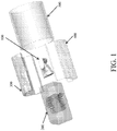
- FIG. 1 An exemplary embodiment of the bioreactor culture chamber is illustrated in FIG. 1 and includes five main components. These components include: a complex scaffold 100, a Polydimethylsiloxane (PDMS) block 200, two fluid-routing manifolds 300,400, and a case 500.
- a complex scaffold 100 is inserted into the PDMS block 200, which is specifically fabricated to match the construct shape.
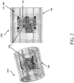
- the PDMS block 200 is sandwiched between two fluid-routing manifolds 300,400, while a tubular enclosure 500 slides over the assembly, providing a compressive force to tightly seal all the individual components together (as shown in FIG. 2 ) as an assembled unit 1000.
- the fluid-routing manifolds 300, 400 are designed with a plurality of ports for medium perfusion.
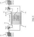
- FIG. 3 demonstrates the fluid-routing manifolds 300, 400 with two inlets 301, 302 and two outlets 401, 402 (wherein the direction of flow is denoted by the arrows) allowing introduction of two different types of fluid 310, 320 ("Media #1" and "Media #2").
- the fluid-routing manifolds 300, 400 spatially distribute flowing fluid into different regions of the PDMS block 200 and to the scaffold 100.
- channels 330 within the PDMS block 200 are sized according to the local scaffold thickness and are positioned to provide a desired fluid flow scheme throughout the scaffold.
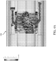
- FIG. 4 depicts flow simulation for a given design as predicted using computational fluid dynamics data calculation and visualization techniques.
- the larger-diameter channels can be placed in the thicker region and smaller diameter channels are placed in the thinner region, in a way providing the exact same flow path resistance.
- the spacing of the channels in either region can be defined ( e.g., for a specific type and density of cells) to provide a desired substantial concentration, i.e., oxygen in the tissue space.
- the number, sizes and placement of perfusion channels can be determined by computational flow dynamics modeling to obtain desired distribution scheme of fluid flow.
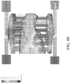
- the mold to create PDMS block can be created, as shown in FIG. 5 .
- the PDMS block fabrication technique includes four components: two cases with predetermined channels 210, 220; a positive scaffold-shape mold with predetermined channels 230; and rods 240 of various sizes. The mold is used to create a PDMS block 200.
- the positive scaffold-shape mold and the outside casing containing the pre-determined holes for channels can be fabricated via 3D printed or machined.
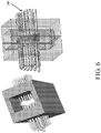
- Multiple rods 240 are inserted through the pre-determined holes of the outside casing 210, 220 into the positive scaffold-shape mold as shown in FIG.6 .
- PDMS is poured into the empty space between the two casings and cured to create the negative PDMS block with pre-determined channels. The rods are then removed to create channels with various size and locations, the PDMS block is cut and the positive scaffold-shape mold is removed.
- the materials used to assemble this bioreactor are silicone and plastics, such as polycarbonate and polyetherimides (e.g., Ultem), to allow for monitoring compatibility in CT or MRI.
- the whole chamber can be place in the imaging machines without having to remove or open any parts allowing for sterility during imaging.
- An additional method to fabricate the PDMS block is accomplished via casting PDMS over a 3D printed structure of the manifold channels in a low-melting-temperature material (e.g., wax) as shown in FIG. 7 .
- a low-melting-temperature material e.g., wax
- wax or dissolvable material is 3-D printed to create positive mold 250.
- the mold is inserted into a case 260 and PDMS can be poured from the top. Once cured, the temperature is raised to purge the wax from the PDMS, resulting in a PDMS manifold.
- This same process could also be accomplished with a dissolvable material (e.g. water-soluble).
- the system and methods disclosed herein provide various advantages.
- the present disclosure enables the design of the fluid-routing manifolds that control spatial distribution of one or more types of culture medium into the PDMS block.
- a PDMS block may have multiple channels of different sizes and spacing at any desired location.
- the block is designed by computational flow simulation to match a desired fluid flow distribution within the scaffold.
- Methods to fabricate the channeled PDMS block are provided.
- the design of the bioreactor is compatible with real-time imaging (e.g. , by ⁇ CT and MRI).
- Various alternative methods to fabricate the channeled PDMS block(s) are provided.
- the manifold 302 can be configured with generally planar inner surfaces which include an upper and lower flange that extends radially inward when in the assembled position (or out of the page as shown in FIG. 8 ).
- the manifold 302 also includes a recess portion 304 disposed on a planar side extending between the upper and lower flanges.
- the recess portion 304 is sized and shaped to accommodate a similarly shaped scaffold and/or tissue growth.
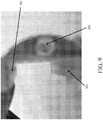
- port 306 is positioned within the recess portion 304 and is configured to allow fluid transfer in a direction that is orthogonal to the longitudinal axis of the bioreactor, when in the assembled position. Fluid is supplied and/or removed from the inner surfaces of the manifold 302 via port 308, as shown in FIG. 9 .
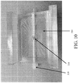
- FIG. 10 depicts another embodiment of the manifold 312.
- the recess portion 314 is configured with a rectangular shape and includes a plurality of channels extending radially outward from the port 316.
- fluid is supplied and/or removed from the inner surfaces of the manifold 312 via port 318.
- FIG. 11 depicts an exemplary PDMS block 202 having a plurality of holes or pores 212 disposed there out to facilitate fluid transfer and tissue generation.
- the sizes of the holes can vary along any given dimension of the scaffold. Likewise the concentration or density of the holes can very along any given dimension of the scaffold.
- FIG. 12 depicts exemplary manifolds 302 and 304, which can be configured to receive fluid routing blocks 322 and 324.
- fluid routing blocks 322 and 324 are configured as separate and discrete parts, which are inserted within the manifolds 302, 304. These fluid routing blocks 322 and 324 in turn are matingly and sealingly coupled to enclose a scaffold 102.
- Fluid routing blocks 322 and 324 can be configured with varying sizes, shapes, and concentration of channels to rout fluid, as so desired. When assembled, these components are nested and coupled and inserted within the case 502.
- Various embodiments of the present disclosure are useful for transport and storage of native tissues, for example allografts for implantation.
- the harvest, evaluation and matching of allografts of bone and cartilage can take about a month (of which about two weeks is attributable to harvesting and screening and two weeks is attributable to tissue matching).
- cell viability decreases to the range of 15-50%.
- Devices according to the present disclosure maintain the viability of these grafts.
- osteochondral allografts have limited availability and a short shelf life of only about 14 days. By placing an ostechondral allograft into a perfusion bioreactor according to the present disclosure, the tissue may be maintained and supported so as to extend the shelf life of the osteochondral tissue.
- a system 1300 for graft maintenance is shown.
- a graft chamber 1301, such as describe further above, is coupled to an environmental control unit 1303 and a media reservoir 1302. Each is in fluid communication with micro-pump 1304.
- Micro-pump 1304 circulates the media through the environmental control unit 1303 and the graft chamber 1301. In some embodiments, micro-pump 1304 is battery powered.
Description
- The disclosed subject matter relates to a system and apparatus for tissue engineering and harvesting. Particularly, the present disclosed subject matter is directed toward utilization of perfusion bioreactor chamber for engineering a broad spectrum of tissues that allows controlled distribution of fluid through or around scaffolding materials of various shapes, structures and topologies during prolonged periods of cultivation.
- In the tissue engineering field, the present disclosure greatly simplifies and improves the techniques to optimize the properties of complex-shaped, multi-phase tissues for implantation and scientific research, as well as enable more insight into the tissue growth without interrupting culture.
- A bioreactor chamber is disclosed in W.L. Grayson, et al.: "Engineering anatomically shaped human bone grafts", Proceedings of the National Academy of Sciences, vol. 107, No. 8, 9 October 2009 (2009-10-09), pages 3299-3304, XP055502838.
- The bioreactor chamber disclosed in the above-mentioned publication comprises: a scaffold (decellularized bone), one PDMS block, a plurality of manifolds, a plurality of fluid routing blocks configured with fluid routing structural features, and an exterior case. The PDMS block has at least one side, an approximately central cavity and channels extending from the at least one side to the approximately central cavity.
- In the broadest sense, the present application provides for a bioreactor chamber as defined in the claims. According to an aspect of the present disclosure, a bioreactor culture chamber is provided. The bioreactor culture chamber includes a scaffold, at least one PDMS block, a plurality of manifolds, and a plurality of fluid routing blocks. The fluid routing blocks are configure with fluid routing structural features. The fluid routing blocks are configured to be nested within the manifolds. The bioreactor culture chamber also includes a case. The case is disposed exterior of the scaffold, PDMS block and plurality of manifolds.
- According to another aspect of the present disclosure, a bioreactor culture chamber is provided. The bioreactor culture chamber includes a block. The block has at least one side, an approximately central cavity. The block has a plurality of channels extending from the at least one side to the approximately central cavity. The bioreactor culture chamber includes a fluid routing manifold. The fluid routing manifold includes an inlet and an outlet. The fluid routing manifold is in fluid communication with the plurality of channels. The bioreactor culture chamber includes an enclosure disposed about an exterior of the fluid routing manifold.
- In some embodiments, the enclosure is substantially tubular. In some embodiments, the block comprises PDMS. In some embodiments, the enclosure exerts a compressive force on the fluid routing manifold. In some embodiments, the plurality of channels is configured such that each of the plurality of channels has substantially the same flow path resistance. In some embodiments, the bioreactor culture chamber includes a scaffold disposed within the approximately central cavity. In some embodiments, the scaffold comprises a plurality of cells. In some embodiments, the inlet is in fluid communication with a reservoir. In some embodiments, the reservoir comprises a nutrient solution. In some embodiments, the block and the enclosure are substantially transparent to x-rays. In some embodiments, the block and the enclosure are substantially transparent to MRI. In some embodiments, bioreactor culture chamber includes an additional fluid routing manifold having an inlet and an outlet. In such embodiments, the enclosure is disposed about an exterior of the additional fluid routing manifold. In some embodiments, the scaffold and the approximately central cavity are substantially the same shape.
- A detailed description of various aspects, features, and embodiments of the subject matter described herein is provided with reference to the accompanying drawings, which are briefly described below. The drawings are illustrative and are not necessarily drawn to scale, with some components and features being exaggerated for clarity. The drawings illustrate various aspects and features of the present subject matter and may illustrate one or more embodiment(s) or example(s) of the present subject matter in whole or in part.
-
FIG. 1 is a schematic representation of an exploded-view of the components of the bioreactor culture chamber in accordance with the disclosed subject matter. -
FIG. 2 is a schematic representation of the assembled bioreactor culture chamber ofFIG. 1 . -
FIG. 3 is a schematic view of an exemplary embodiment of dual medium perfusion in accordance with the disclosed subject matter. -
FIGS. 4A-B are computational fluid dynamic plots demonstrating flow simulation, which can determine desired fluid flow scheme and design PDMS block. -
FIG. 5 is a schematic representation of an exploded-view of an exemplary PDMS block fabrication technique in accordance with the disclosed subject matter. -
FIG. 6 is a schematic representation of the assembled PDMS block fabrication ofFIG. 5 . -
FIG. 7 is a schematic representation of an exploded-view of another exemplary PDMS block fabrication technique in accordance with the disclosed subject matter. -
FIG. 8 is a schematic view of an alternative embodiment of a manifold, in accordance with the disclosed subject matter. -
FIG. 9 is a front view of the embodiment ofFIG. 8 . -
FIG. 10 is a schematic view of an alternative embodiment of a manifold, in accordance with the disclosed subject matter. -
FIG. 11 is an alternative embodiment of the PDMS block, in accordance with the disclosed subject matter. -
FIG. 12 is a schematic representation of an exploded-view of the components of an alternative embodiment of the bioreactor culture chamber in accordance with the disclosed subject matter. -
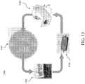
FIG. 13 is a diagram of a system for the maintenance of cell viability for osteochondral allografts according to an embodiment of the present disclosure. - Reference will now be made in detail to exemplary embodiments of the disclosed subject matter, an example of which is illustrated in the accompanying drawings. The apparatus and corresponding method of the disclosed subject matter will be described in conjunction with the detailed description of the system.
- The methods and systems presented herein may be used for the design and utilization of a perfusion bioreactor chamber for engineering a broad spectrum of tissues that allows controlled distribution of fluid through or around scaffolding materials of various shapes, structures and topologies during prolonged periods of cultivation. The bioreactor disclosed herein also allows for use of two or more different culture media (e.g., to support the formation of composite tissues), control of oxygen concentration inside the tissue, and live imaging (e.g., by µCT, MRI) without interruption of culture.
- An exemplary embodiment of the bioreactor culture chamber is illustrated in
FIG. 1 and includes five main components. These components include: acomplex scaffold 100, a Polydimethylsiloxane (PDMS)block 200, two fluid-routing manifolds 300,400, and acase 500. To assemble the bioreactor, thescaffold 100 is inserted into thePDMS block 200, which is specifically fabricated to match the construct shape. ThePDMS block 200 is sandwiched between two fluid-routing manifolds 300,400, while atubular enclosure 500 slides over the assembly, providing a compressive force to tightly seal all the individual components together (as shown inFIG. 2 ) as an assembledunit 1000. The fluid-routingmanifolds -
FIG. 3 demonstrates the fluid-routingmanifolds inlets outlets 401, 402 (wherein the direction of flow is denoted by the arrows) allowing introduction of two different types offluid 310, 320 ("Media # 1" and "Media # 2"). The fluid-routingmanifolds PDMS block 200 and to thescaffold 100. - Large constructs require a well-controlled nutrient supply to support cell viability and stimulate tissue formation. For control medium perfusion,
channels 330 within the PDMS block 200 are sized according to the local scaffold thickness and are positioned to provide a desired fluid flow scheme throughout the scaffold. -
FIG. 4 depicts flow simulation for a given design as predicted using computational fluid dynamics data calculation and visualization techniques. For example, in order to obtain close-to homogenous fluid flow velocity in anatomically shaped scaffolds that have different thicknesses in different locations, the larger-diameter channels can be placed in the thicker region and smaller diameter channels are placed in the thinner region, in a way providing the exact same flow path resistance. Additionally or alternatively, the spacing of the channels in either region can be defined (e.g., for a specific type and density of cells) to provide a desired substantial concentration, i.e., oxygen in the tissue space. - The number, sizes and placement of perfusion channels can be determined by computational flow dynamics modeling to obtain desired distribution scheme of fluid flow. Once the distribution and size of channels to provide desired scheme of fluid flow is determined for a given embodiment, the mold to create PDMS block can be created, as shown in
FIG. 5 . In the exemplary embodiment shown, the PDMS block fabrication technique includes four components: two cases withpredetermined channels predetermined channels 230; androds 240 of various sizes. The mold is used to create aPDMS block 200. - The positive scaffold-shape mold and the outside casing containing the pre-determined holes for channels can be fabricated via 3D printed or machined.
Multiple rods 240 are inserted through the pre-determined holes of theoutside casing FIG.6 . PDMS is poured into the empty space between the two casings and cured to create the negative PDMS block with pre-determined channels. The rods are then removed to create channels with various size and locations, the PDMS block is cut and the positive scaffold-shape mold is removed. - In accordance with another aspect of the disclosure, and for purpose of illustration and not limitation, the materials used to assemble this bioreactor are silicone and plastics, such as polycarbonate and polyetherimides (e.g., Ultem), to allow for monitoring compatibility in CT or MRI. The whole chamber can be place in the imaging machines without having to remove or open any parts allowing for sterility during imaging.
- An additional method to fabricate the PDMS block is accomplished via casting PDMS over a 3D printed structure of the manifold channels in a low-melting-temperature material (e.g., wax) as shown in
FIG. 7 . Here, wax or dissolvable material is 3-D printed to createpositive mold 250. The mold is inserted into acase 260 and PDMS can be poured from the top. Once cured, the temperature is raised to purge the wax from the PDMS, resulting in a PDMS manifold. This same process could also be accomplished with a dissolvable material (e.g. water-soluble). - In accordance with the present disclosure, the system and methods disclosed herein provide various advantages. The present disclosure enables the design of the fluid-routing manifolds that control spatial distribution of one or more types of culture medium into the PDMS block. A PDMS block may have multiple channels of different sizes and spacing at any desired location. The block is designed by computational flow simulation to match a desired fluid flow distribution within the scaffold. Methods to fabricate the channeled PDMS block are provided. The design of the bioreactor is compatible with real-time imaging (e.g., by µCT and MRI). Various alternative methods to fabricate the channeled PDMS block(s) are provided.
- Additional exemplary embodiments of the disclosed subject matter are provided in
FIGS. 8-13 . As shown inFIGS. 8-9 , the manifold 302 can be configured with generally planar inner surfaces which include an upper and lower flange that extends radially inward when in the assembled position (or out of the page as shown inFIG. 8 ). The manifold 302 also includes arecess portion 304 disposed on a planar side extending between the upper and lower flanges. Therecess portion 304 is sized and shaped to accommodate a similarly shaped scaffold and/or tissue growth. Furthermore,port 306 is positioned within therecess portion 304 and is configured to allow fluid transfer in a direction that is orthogonal to the longitudinal axis of the bioreactor, when in the assembled position. Fluid is supplied and/or removed from the inner surfaces of the manifold 302 viaport 308, as shown inFIG. 9 . - Similarly,
FIG. 10 depicts another embodiment of the manifold 312. In this embodiment therecess portion 314 is configured with a rectangular shape and includes a plurality of channels extending radially outward from theport 316. As described above with respect to the embodiment ofFIG. 9 , fluid is supplied and/or removed from the inner surfaces of the manifold 312 viaport 318. -
FIG. 11 depicts an exemplary PDMS block 202 having a plurality of holes orpores 212 disposed there out to facilitate fluid transfer and tissue generation. The sizes of the holes can vary along any given dimension of the scaffold. Likewise the concentration or density of the holes can very along any given dimension of the scaffold. -
FIG. 12 depictsexemplary manifolds manifolds scaffold 102. Fluid routing blocks 322 and 324 can be configured with varying sizes, shapes, and concentration of channels to rout fluid, as so desired. When assembled, these components are nested and coupled and inserted within thecase 502. - Various embodiments of the present disclosure are useful for transport and storage of native tissues, for example allografts for implantation. The harvest, evaluation and matching of allografts of bone and cartilage can take about a month (of which about two weeks is attributable to harvesting and screening and two weeks is attributable to tissue matching). During this time, cell viability decreases to the range of 15-50%. Devices according to the present disclosure maintain the viability of these grafts. For example, osteochondral allografts have limited availability and a short shelf life of only about 14 days. By placing an ostechondral allograft into a perfusion bioreactor according to the present disclosure, the tissue may be maintained and supported so as to extend the shelf life of the osteochondral tissue.
- Referring to
FIG. 13 , asystem 1300 for graft maintenance is shown. Agraft chamber 1301, such as describe further above, is coupled to anenvironmental control unit 1303 and amedia reservoir 1302. Each is in fluid communication withmicro-pump 1304.Micro-pump 1304 circulates the media through theenvironmental control unit 1303 and thegraft chamber 1301. In some embodiments, micro-pump 1304 is battery powered. - While the disclosed subject matter is described herein in terms of certain preferred embodiments, those skilled in the art will recognize that various modifications and improvements may be made to the disclosed subject matter without departing from the scope thereof. Moreover, although individual features of one embodiment of the disclosed subject matter may be discussed herein or shown in the drawings of the one embodiment and not in other embodiments, it should be apparent that individual features of one embodiment may be combined with one or more features of another embodiment or features from a plurality of embodiments.
- In addition to the specific embodiments claimed below, the disclosed subject matter is also directed to other embodiments having any other possible combination of the dependent features claimed below and those disclosed above. As such, the particular features presented in the dependent claims and disclosed above can be combined with each other in other manners within the scope of the disclosed subject matter such that the disclosed subject matter should be recognized as also specifically directed to other embodiments having any other possible combinations. Thus, the foregoing description of specific embodiments of the disclosed subject matter has been presented for purposes of illustration and description. It is not intended to be exhaustive or to limit the disclosed subject matter to those embodiments disclosed.
- It will be apparent to those skilled in the art that various modifications and variations can be made in the method and system of the disclosed subject matter without departing from the spirit or scope of the disclosed subject matter. Thus, it is intended that the disclosed subject matter include modifications and variations that are within the scope of the appended claims and their equivalents.
Claims (13)
- A bioreactor culture chamber comprising:a block (200) having at least one side, an approximately central cavity, a scaffold (100) disposed within the approximately central cavity and having different thickness in different regions, and a plurality of channels (330) extending from the at least one side to the approximately central cavity;a fluid routing manifold (300, 400) having an inlet (301, 302) and an outlet (401, 402), the fluid routing manifold in fluid communication with the plurality of channels; wherein the plurality of channels (330) are sized and positioned with larger-diameter channels placed in relation to thicker regions of the scaffold and smaller-diameter channels placed in relation to thinner regions of the scaffold so that each of the plurality of channels provides substantially the same flow path resistance within the scaffold; andan enclosure (500) disposed about an exterior of the fluid routing manifold.
- The bioreactor of claim 1, wherein the enclosure (500) is substantially tubular.
- The bioreactor of claim 1, wherein the block (200) comprises PDMS.
- The bioreactor of claim 1, wherein the enclosure (500) exerts a compressive force on the fluid routing manifold (300, 400).
- The bioreactor of claim 1, wherein the plurality of channels (330) is configured such that each of the plurality of channels has substantially the same flow path resistance.
- The bioreactor of claim 1, wherein the scaffold (100) comprises a plurality of cells.
- The bioreactor of claim 1, wherein the inlet (301, 302) is in fluid communication with a reservoir.
- The bioreactor of claim 7, wherein the reservoir comprises a nutrient solution.
- The bioreactor of claim 1, wherein the block (200) and the enclosure (500) are substantially transparent to x-rays.
- The bioreactor of claim 1, wherein the block (200) and the enclosure (500) are substantially transparent to MRI.
- The bioreactor of claim 1, further comprising an additional fluid routing manifold having an inlet and an outlet, wherein the enclosure (500) is disposed about an exterior of the additional fluid routing manifold.
- The bioreactor of claim 1, wherein the scaffold (100) and the approximately central cavity are substantially the same shape.
- The bioreactor of claim 1, comprising:a plurality of said fluid routing manifolds (300, 302, 304, 312, 400), anda plurality of fluid routing blocks (322, 324) configured with fluid routing structural features, the fluid routing blocks configured to be nested within the fluid routing manifolds.
Applications Claiming Priority (3)
| Application Number | Priority Date | Filing Date | Title |
|---|---|---|---|
| US201361813378P | 2013-04-18 | 2013-04-18 | |
| US201361857490P | 2013-07-23 | 2013-07-23 | |
| PCT/US2014/034559 WO2014172575A1 (en) | 2013-04-18 | 2014-04-17 | Perfusion bioreactor with tissue flow control and live imaging compatibility |
Publications (3)
| Publication Number | Publication Date |
|---|---|
| EP2986705A1 EP2986705A1 (en) | 2016-02-24 |
| EP2986705A4 EP2986705A4 (en) | 2016-12-14 |
| EP2986705B1 true EP2986705B1 (en) | 2020-03-25 |
Family
ID=51731857
Family Applications (1)
| Application Number | Title | Priority Date | Filing Date |
|---|---|---|---|
| EP14784780.0A Active EP2986705B1 (en) | 2013-04-18 | 2014-04-17 | Perfusion bioreactor with tissue flow control and live imaging compatibility |
Country Status (8)
| Country | Link |
|---|---|
| US (2) | US10301584B2 (en) |
| EP (1) | EP2986705B1 (en) |
| JP (2) | JP6449855B2 (en) |
| KR (1) | KR102280214B1 (en) |
| CN (3) | CN114703059A (en) |
| AU (1) | AU2014253850B2 (en) |
| CA (1) | CA2909187C (en) |
| WO (1) | WO2014172575A1 (en) |
Families Citing this family (4)
| Publication number | Priority date | Publication date | Assignee | Title |
|---|---|---|---|---|
| JP6866314B2 (en) | 2015-08-17 | 2021-04-28 | フィリップ・モーリス・プロダクツ・ソシエテ・アノニム | Aerosol generation system and aerosol generation articles for use in that system |
| WO2018035182A1 (en) * | 2016-08-16 | 2018-02-22 | The Trustees Of Columbia University In The City Of New York | Storage and preservation of living tissue allografts |
| FR3088341B1 (en) | 2018-11-09 | 2023-10-06 | Inst Mines Telecom | CELL CULTURE DEVICE |
| WO2022112968A1 (en) | 2020-11-25 | 2022-06-02 | Association For The Advancement Of Tissue Engineering And Cell Based Technologies & Therapies (A4Tec) - Associação | Bioreactor for tissue engineering of multi-tissue structure and manufacturing method thereof |
Family Cites Families (9)
| Publication number | Priority date | Publication date | Assignee | Title |
|---|---|---|---|---|
| US5416022A (en) * | 1988-08-10 | 1995-05-16 | Cellex Biosciences, Inc. | Cell culture apparatus |
| US5827729A (en) * | 1996-04-23 | 1998-10-27 | Advanced Tissue Sciences | Diffusion gradient bioreactor and extracorporeal liver device using a three-dimensional liver tissue |
| US20020110905A1 (en) | 2001-02-15 | 2002-08-15 | Emilio Barbera-Guillem | Perfusion system for cultured cells |
| JP2010536348A (en) * | 2007-08-24 | 2010-12-02 | スマート・バイオシステムズ・エーピーエス | Medium scale bioreactor platform for perfusion |
| US9410113B2 (en) * | 2007-10-26 | 2016-08-09 | St3 Development Corporation | Bioreactor system for three-dimensional tissue stimulator |
| CA2613945A1 (en) * | 2007-12-12 | 2009-06-12 | The Hospital For Sick Children | Bladder bioreactor |
| WO2010102059A1 (en) | 2009-03-03 | 2010-09-10 | The Trustees Of Columbia University In The City Of New York | Methods, devices, and systems for bone tissue engineering using a bioreactor |
| EP2438153A1 (en) * | 2009-06-03 | 2012-04-11 | Aarhus Universitet | Submerged perfusion bioreactor |
| US9206383B2 (en) * | 2009-12-07 | 2015-12-08 | The Trustees Of Columbia University In The City Of New York | Bioreactor, devices, systems and methods |
-
2014
- 2014-04-17 WO PCT/US2014/034559 patent/WO2014172575A1/en active Application Filing
- 2014-04-17 CN CN202210398863.3A patent/CN114703059A/en active Pending
- 2014-04-17 AU AU2014253850A patent/AU2014253850B2/en active Active
- 2014-04-17 CA CA2909187A patent/CA2909187C/en active Active
- 2014-04-17 CN CN201480021924.8A patent/CN105283538A/en active Pending
- 2014-04-17 KR KR1020157032861A patent/KR102280214B1/en active IP Right Grant
- 2014-04-17 JP JP2016509109A patent/JP6449855B2/en active Active
- 2014-04-17 CN CN202210399803.3A patent/CN114672417A/en active Pending
- 2014-04-17 EP EP14784780.0A patent/EP2986705B1/en active Active
- 2014-04-17 US US14/782,630 patent/US10301584B2/en active Active
-
2018
- 2018-12-06 JP JP2018229138A patent/JP6845212B2/en active Active
-
2019
- 2019-04-02 US US16/373,516 patent/US10889789B2/en active Active
Non-Patent Citations (1)
| Title |
|---|
| W. L. GRAYSON ET AL: "Engineering anatomically shaped human bone grafts", PROCEEDINGS OF THE NATIONAL ACADEMY OF SCIENCES, vol. 107, no. 8, 9 October 2009 (2009-10-09), US, pages 3299 - 3304, XP055502838, ISSN: 0027-8424, DOI: 10.1073/pnas.0905439106 * |
Also Published As
| Publication number | Publication date |
|---|---|
| KR20150143819A (en) | 2015-12-23 |
| WO2014172575A1 (en) | 2014-10-23 |
| KR102280214B1 (en) | 2021-07-21 |
| JP2019033768A (en) | 2019-03-07 |
| CA2909187C (en) | 2023-02-07 |
| EP2986705A1 (en) | 2016-02-24 |
| US20160040108A1 (en) | 2016-02-11 |
| CN114703059A (en) | 2022-07-05 |
| CA2909187A1 (en) | 2014-10-23 |
| US20190225925A1 (en) | 2019-07-25 |
| AU2014253850A1 (en) | 2015-10-15 |
| US10889789B2 (en) | 2021-01-12 |
| AU2014253850B2 (en) | 2019-05-16 |
| CN114672417A (en) | 2022-06-28 |
| JP6449855B2 (en) | 2019-01-09 |
| JP6845212B2 (en) | 2021-03-17 |
| EP2986705A4 (en) | 2016-12-14 |
| CN105283538A (en) | 2016-01-27 |
| JP2016515402A (en) | 2016-05-30 |
| US10301584B2 (en) | 2019-05-28 |
Similar Documents
| Publication | Publication Date | Title |
|---|---|---|
| US10889789B2 (en) | Perfusion bioreactor with tissue flow control and live imaging compatibility | |
| ES2580804T3 (en) | Methods, devices and systems for bone tissue engineering using a bioreactor | |
| CA2784100C (en) | A continuous culturing device comprising a scaffold matrix of interconnected growth surfaces | |
| Panoskaltsis-Mortari | Bioreactor development for lung tissue engineering | |
| KR102441836B1 (en) | Module type cell culture device | |
| US20150322397A1 (en) | Bioreactor Cartridge and System | |
| TW202022107A (en) | Continuous flow microbioreactor | |
| He et al. | Why choose 3D bioprinting? Part I: a brief introduction of 3D bioprinting for the beginners | |
| Pino et al. | Bioengineered renal cell therapy device for clinical translation | |
| US20230357692A1 (en) | Cell culture apparatus | |
| EP2800807B1 (en) | Bioreactor composed of watertight chamber and internal matrix for the generation of cellularized medical implants | |
| Allori et al. | Design and validation of a dynamic cell‐culture system for bone biology research and exogenous tissue‐engineering applications | |
| Thilmany | Printed life | |
| O'Grady et al. | Spatiotemporal Control of Morphogen Delivery to Pattern Stem Cell Differentiation in Three‐Dimensional Hydrogels | |
| JPS61500052A (en) | Cell culture system | |
| Karp et al. | Disease modeling with kidney organoids | |
| Zhu et al. | Design and fabrication of the vertical-flow bioreactor for compaction hepatocyte culture in drug testing application | |
| US20050049581A1 (en) | Hybrid organ circulatory system | |
| US11959060B1 (en) | Fluid systems, apparatuses, devices and methods of management thereof for cultivating tissue | |
| Benc et al. | Improving the quality of oocytes with the help of nucleolotransfer therapy | |
| McClelland et al. | Construction of a multicoaxial hollow fiber bioreactor | |
| MOGENTALE | Design and development of a novel automatic system for bioreactor culture medium exchange | |
| CN102166380A (en) | Perfusion type bioartificial liver reactor based on double-layered nitrocellulose membrane |
Legal Events
| Date | Code | Title | Description |
|---|---|---|---|
| PUAI | Public reference made under article 153(3) epc to a published international application that has entered the european phase |
Free format text: ORIGINAL CODE: 0009012 |
|
| 17P | Request for examination filed |
Effective date: 20151105 |
|
| AK | Designated contracting states |
Kind code of ref document: A1 Designated state(s): AL AT BE BG CH CY CZ DE DK EE ES FI FR GB GR HR HU IE IS IT LI LT LU LV MC MK MT NL NO PL PT RO RS SE SI SK SM TR |
|
| AX | Request for extension of the european patent |
Extension state: BA ME |
|
| RIN1 | Information on inventor provided before grant (corrected) |
Inventor name: YEAGER, KEITH Inventor name: BHUMIRATANA, SARINDR Inventor name: VUNJAK-NOVAKOVIC, GORDANA |
|
| DAX | Request for extension of the european patent (deleted) | ||
| RIN1 | Information on inventor provided before grant (corrected) |
Inventor name: BHUMIRATANA, SARINDR Inventor name: YEAGER, KEITH Inventor name: VUNJAK-NOVAKOVIC, GORDANA |
|
| A4 | Supplementary search report drawn up and despatched |
Effective date: 20161114 |
|
| RIC1 | Information provided on ipc code assigned before grant |
Ipc: C12M 3/00 20060101AFI20161108BHEP Ipc: C12M 1/12 20060101ALI20161108BHEP Ipc: C12M 1/00 20060101ALI20161108BHEP |
|
| STAA | Information on the status of an ep patent application or granted ep patent |
Free format text: STATUS: EXAMINATION IS IN PROGRESS |
|
| 17Q | First examination report despatched |
Effective date: 20180910 |
|
| GRAP | Despatch of communication of intention to grant a patent |
Free format text: ORIGINAL CODE: EPIDOSNIGR1 |
|
| STAA | Information on the status of an ep patent application or granted ep patent |
Free format text: STATUS: GRANT OF PATENT IS INTENDED |
|
| INTG | Intention to grant announced |
Effective date: 20190520 |
|
| GRAJ | Information related to disapproval of communication of intention to grant by the applicant or resumption of examination proceedings by the epo deleted |
Free format text: ORIGINAL CODE: EPIDOSDIGR1 |
|
| STAA | Information on the status of an ep patent application or granted ep patent |
Free format text: STATUS: EXAMINATION IS IN PROGRESS |
|
| GRAP | Despatch of communication of intention to grant a patent |
Free format text: ORIGINAL CODE: EPIDOSNIGR1 |
|
| STAA | Information on the status of an ep patent application or granted ep patent |
Free format text: STATUS: GRANT OF PATENT IS INTENDED |
|
| INTG | Intention to grant announced |
Effective date: 20191011 |
|
| GRAS | Grant fee paid |
Free format text: ORIGINAL CODE: EPIDOSNIGR3 |
|
| GRAA | (expected) grant |
Free format text: ORIGINAL CODE: 0009210 |
|
| STAA | Information on the status of an ep patent application or granted ep patent |
Free format text: STATUS: THE PATENT HAS BEEN GRANTED |
|
| AK | Designated contracting states |
Kind code of ref document: B1 Designated state(s): AL AT BE BG CH CY CZ DE DK EE ES FI FR GB GR HR HU IE IS IT LI LT LU LV MC MK MT NL NO PL PT RO RS SE SI SK SM TR |
|
| REG | Reference to a national code |
Ref country code: GB Ref legal event code: FG4D |
|
| REG | Reference to a national code |
Ref country code: CH Ref legal event code: NV Representative=s name: VALIPAT S.A. C/O BOVARD SA NEUCHATEL, CH Ref country code: AT Ref legal event code: REF Ref document number: 1248557 Country of ref document: AT Kind code of ref document: T Effective date: 20200415 Ref country code: IE Ref legal event code: FG4D |
|
| REG | Reference to a national code |
Ref country code: DE Ref legal event code: R096 Ref document number: 602014062866 Country of ref document: DE |
|
| PG25 | Lapsed in a contracting state [announced via postgrant information from national office to epo] |
Ref country code: NO Free format text: LAPSE BECAUSE OF FAILURE TO SUBMIT A TRANSLATION OF THE DESCRIPTION OR TO PAY THE FEE WITHIN THE PRESCRIBED TIME-LIMIT Effective date: 20200625 Ref country code: RS Free format text: LAPSE BECAUSE OF FAILURE TO SUBMIT A TRANSLATION OF THE DESCRIPTION OR TO PAY THE FEE WITHIN THE PRESCRIBED TIME-LIMIT Effective date: 20200325 Ref country code: FI Free format text: LAPSE BECAUSE OF FAILURE TO SUBMIT A TRANSLATION OF THE DESCRIPTION OR TO PAY THE FEE WITHIN THE PRESCRIBED TIME-LIMIT Effective date: 20200325 |
|
| PG25 | Lapsed in a contracting state [announced via postgrant information from national office to epo] |
Ref country code: HR Free format text: LAPSE BECAUSE OF FAILURE TO SUBMIT A TRANSLATION OF THE DESCRIPTION OR TO PAY THE FEE WITHIN THE PRESCRIBED TIME-LIMIT Effective date: 20200325 Ref country code: SE Free format text: LAPSE BECAUSE OF FAILURE TO SUBMIT A TRANSLATION OF THE DESCRIPTION OR TO PAY THE FEE WITHIN THE PRESCRIBED TIME-LIMIT Effective date: 20200325 Ref country code: LV Free format text: LAPSE BECAUSE OF FAILURE TO SUBMIT A TRANSLATION OF THE DESCRIPTION OR TO PAY THE FEE WITHIN THE PRESCRIBED TIME-LIMIT Effective date: 20200325 Ref country code: GR Free format text: LAPSE BECAUSE OF FAILURE TO SUBMIT A TRANSLATION OF THE DESCRIPTION OR TO PAY THE FEE WITHIN THE PRESCRIBED TIME-LIMIT Effective date: 20200626 Ref country code: BG Free format text: LAPSE BECAUSE OF FAILURE TO SUBMIT A TRANSLATION OF THE DESCRIPTION OR TO PAY THE FEE WITHIN THE PRESCRIBED TIME-LIMIT Effective date: 20200625 |
|
| REG | Reference to a national code |
Ref country code: NL Ref legal event code: MP Effective date: 20200325 |
|
| REG | Reference to a national code |
Ref country code: LT Ref legal event code: MG4D |
|
| PG25 | Lapsed in a contracting state [announced via postgrant information from national office to epo] |
Ref country code: NL Free format text: LAPSE BECAUSE OF FAILURE TO SUBMIT A TRANSLATION OF THE DESCRIPTION OR TO PAY THE FEE WITHIN THE PRESCRIBED TIME-LIMIT Effective date: 20200325 |
|
| PG25 | Lapsed in a contracting state [announced via postgrant information from national office to epo] |
Ref country code: CZ Free format text: LAPSE BECAUSE OF FAILURE TO SUBMIT A TRANSLATION OF THE DESCRIPTION OR TO PAY THE FEE WITHIN THE PRESCRIBED TIME-LIMIT Effective date: 20200325 Ref country code: RO Free format text: LAPSE BECAUSE OF FAILURE TO SUBMIT A TRANSLATION OF THE DESCRIPTION OR TO PAY THE FEE WITHIN THE PRESCRIBED TIME-LIMIT Effective date: 20200325 Ref country code: LT Free format text: LAPSE BECAUSE OF FAILURE TO SUBMIT A TRANSLATION OF THE DESCRIPTION OR TO PAY THE FEE WITHIN THE PRESCRIBED TIME-LIMIT Effective date: 20200325 Ref country code: EE Free format text: LAPSE BECAUSE OF FAILURE TO SUBMIT A TRANSLATION OF THE DESCRIPTION OR TO PAY THE FEE WITHIN THE PRESCRIBED TIME-LIMIT Effective date: 20200325 Ref country code: SM Free format text: LAPSE BECAUSE OF FAILURE TO SUBMIT A TRANSLATION OF THE DESCRIPTION OR TO PAY THE FEE WITHIN THE PRESCRIBED TIME-LIMIT Effective date: 20200325 Ref country code: PT Free format text: LAPSE BECAUSE OF FAILURE TO SUBMIT A TRANSLATION OF THE DESCRIPTION OR TO PAY THE FEE WITHIN THE PRESCRIBED TIME-LIMIT Effective date: 20200818 Ref country code: SK Free format text: LAPSE BECAUSE OF FAILURE TO SUBMIT A TRANSLATION OF THE DESCRIPTION OR TO PAY THE FEE WITHIN THE PRESCRIBED TIME-LIMIT Effective date: 20200325 Ref country code: IS Free format text: LAPSE BECAUSE OF FAILURE TO SUBMIT A TRANSLATION OF THE DESCRIPTION OR TO PAY THE FEE WITHIN THE PRESCRIBED TIME-LIMIT Effective date: 20200725 |
|
| REG | Reference to a national code |
Ref country code: AT Ref legal event code: MK05 Ref document number: 1248557 Country of ref document: AT Kind code of ref document: T Effective date: 20200325 |
|
| PG25 | Lapsed in a contracting state [announced via postgrant information from national office to epo] |
Ref country code: MC Free format text: LAPSE BECAUSE OF FAILURE TO SUBMIT A TRANSLATION OF THE DESCRIPTION OR TO PAY THE FEE WITHIN THE PRESCRIBED TIME-LIMIT Effective date: 20200325 |
|
| REG | Reference to a national code |
Ref country code: DE Ref legal event code: R097 Ref document number: 602014062866 Country of ref document: DE |
|
| PG25 | Lapsed in a contracting state [announced via postgrant information from national office to epo] |
Ref country code: DK Free format text: LAPSE BECAUSE OF FAILURE TO SUBMIT A TRANSLATION OF THE DESCRIPTION OR TO PAY THE FEE WITHIN THE PRESCRIBED TIME-LIMIT Effective date: 20200325 Ref country code: LU Free format text: LAPSE BECAUSE OF NON-PAYMENT OF DUE FEES Effective date: 20200417 Ref country code: AT Free format text: LAPSE BECAUSE OF FAILURE TO SUBMIT A TRANSLATION OF THE DESCRIPTION OR TO PAY THE FEE WITHIN THE PRESCRIBED TIME-LIMIT Effective date: 20200325 Ref country code: ES Free format text: LAPSE BECAUSE OF FAILURE TO SUBMIT A TRANSLATION OF THE DESCRIPTION OR TO PAY THE FEE WITHIN THE PRESCRIBED TIME-LIMIT Effective date: 20200325 Ref country code: IT Free format text: LAPSE BECAUSE OF FAILURE TO SUBMIT A TRANSLATION OF THE DESCRIPTION OR TO PAY THE FEE WITHIN THE PRESCRIBED TIME-LIMIT Effective date: 20200325 |
|
| PLBE | No opposition filed within time limit |
Free format text: ORIGINAL CODE: 0009261 |
|
| STAA | Information on the status of an ep patent application or granted ep patent |
Free format text: STATUS: NO OPPOSITION FILED WITHIN TIME LIMIT |
|
| PG25 | Lapsed in a contracting state [announced via postgrant information from national office to epo] |
Ref country code: PL Free format text: LAPSE BECAUSE OF FAILURE TO SUBMIT A TRANSLATION OF THE DESCRIPTION OR TO PAY THE FEE WITHIN THE PRESCRIBED TIME-LIMIT Effective date: 20200325 |
|
| 26N | No opposition filed |
Effective date: 20210112 |
|
| PG25 | Lapsed in a contracting state [announced via postgrant information from national office to epo] |
Ref country code: IE Free format text: LAPSE BECAUSE OF NON-PAYMENT OF DUE FEES Effective date: 20200417 |
|
| PG25 | Lapsed in a contracting state [announced via postgrant information from national office to epo] |
Ref country code: SI Free format text: LAPSE BECAUSE OF FAILURE TO SUBMIT A TRANSLATION OF THE DESCRIPTION OR TO PAY THE FEE WITHIN THE PRESCRIBED TIME-LIMIT Effective date: 20200325 |
|
| PG25 | Lapsed in a contracting state [announced via postgrant information from national office to epo] |
Ref country code: TR Free format text: LAPSE BECAUSE OF FAILURE TO SUBMIT A TRANSLATION OF THE DESCRIPTION OR TO PAY THE FEE WITHIN THE PRESCRIBED TIME-LIMIT Effective date: 20200325 Ref country code: MT Free format text: LAPSE BECAUSE OF FAILURE TO SUBMIT A TRANSLATION OF THE DESCRIPTION OR TO PAY THE FEE WITHIN THE PRESCRIBED TIME-LIMIT Effective date: 20200325 Ref country code: CY Free format text: LAPSE BECAUSE OF FAILURE TO SUBMIT A TRANSLATION OF THE DESCRIPTION OR TO PAY THE FEE WITHIN THE PRESCRIBED TIME-LIMIT Effective date: 20200325 |
|
| PG25 | Lapsed in a contracting state [announced via postgrant information from national office to epo] |
Ref country code: MK Free format text: LAPSE BECAUSE OF FAILURE TO SUBMIT A TRANSLATION OF THE DESCRIPTION OR TO PAY THE FEE WITHIN THE PRESCRIBED TIME-LIMIT Effective date: 20200325 Ref country code: AL Free format text: LAPSE BECAUSE OF FAILURE TO SUBMIT A TRANSLATION OF THE DESCRIPTION OR TO PAY THE FEE WITHIN THE PRESCRIBED TIME-LIMIT Effective date: 20200325 |
|
| P01 | Opt-out of the competence of the unified patent court (upc) registered |
Effective date: 20230314 |
|
| REG | Reference to a national code |
Ref country code: DE Ref legal event code: R082 Ref document number: 602014062866 Country of ref document: DE Representative=s name: ALPSPITZ IP ALLGAYER UND PARTNER PATENTANWAELT, DE |
|
| PGFP | Annual fee paid to national office [announced via postgrant information from national office to epo] |
Ref country code: GB Payment date: 20230921 Year of fee payment: 10 |
|
| PGFP | Annual fee paid to national office [announced via postgrant information from national office to epo] |
Ref country code: FR Payment date: 20230927 Year of fee payment: 10 Ref country code: DE Payment date: 20230919 Year of fee payment: 10 Ref country code: BE Payment date: 20230926 Year of fee payment: 10 |
|
| PGFP | Annual fee paid to national office [announced via postgrant information from national office to epo] |
Ref country code: CH Payment date: 20231003 Year of fee payment: 10 |