EP2986550B1 - Load bearing apparatus and method - Google Patents
Load bearing apparatus and method Download PDFInfo
- Publication number
- EP2986550B1 EP2986550B1 EP14718699.3A EP14718699A EP2986550B1 EP 2986550 B1 EP2986550 B1 EP 2986550B1 EP 14718699 A EP14718699 A EP 14718699A EP 2986550 B1 EP2986550 B1 EP 2986550B1
- Authority
- EP
- European Patent Office
- Prior art keywords
- load
- bearing
- tension
- bearing elements
- winch
- Prior art date
- Legal status (The legal status is an assumption and is not a legal conclusion. Google has not performed a legal analysis and makes no representation as to the accuracy of the status listed.)
- Active
Links
Images

Classifications
-
- B—PERFORMING OPERATIONS; TRANSPORTING
- B66—HOISTING; LIFTING; HAULING
- B66D—CAPSTANS; WINCHES; TACKLES, e.g. PULLEY BLOCKS; HOISTS
- B66D1/00—Rope, cable, or chain winding mechanisms; Capstans
- B66D1/60—Rope, cable, or chain winding mechanisms; Capstans adapted for special purposes
- B66D1/74—Capstans
- B66D1/7442—Capstans having a horizontal rotation axis
-
- B—PERFORMING OPERATIONS; TRANSPORTING
- B66—HOISTING; LIFTING; HAULING
- B66D—CAPSTANS; WINCHES; TACKLES, e.g. PULLEY BLOCKS; HOISTS
- B66D1/00—Rope, cable, or chain winding mechanisms; Capstans
- B66D1/28—Other constructional details
- B66D1/30—Rope, cable, or chain drums or barrels
-
- B—PERFORMING OPERATIONS; TRANSPORTING
- B66—HOISTING; LIFTING; HAULING
- B66D—CAPSTANS; WINCHES; TACKLES, e.g. PULLEY BLOCKS; HOISTS
- B66D1/00—Rope, cable, or chain winding mechanisms; Capstans
- B66D1/28—Other constructional details
- B66D1/40—Control devices
- B66D1/48—Control devices automatic
- B66D1/50—Control devices automatic for maintaining predetermined rope, cable, or chain tension, e.g. in ropes or cables for towing craft, in chains for anchors; Warping or mooring winch-cable tension control
-
- B—PERFORMING OPERATIONS; TRANSPORTING
- B66—HOISTING; LIFTING; HAULING
- B66D—CAPSTANS; WINCHES; TACKLES, e.g. PULLEY BLOCKS; HOISTS
- B66D1/00—Rope, cable, or chain winding mechanisms; Capstans
- B66D1/28—Other constructional details
- B66D1/40—Control devices
- B66D1/48—Control devices automatic
- B66D1/50—Control devices automatic for maintaining predetermined rope, cable, or chain tension, e.g. in ropes or cables for towing craft, in chains for anchors; Warping or mooring winch-cable tension control
- B66D1/505—Control devices automatic for maintaining predetermined rope, cable, or chain tension, e.g. in ropes or cables for towing craft, in chains for anchors; Warping or mooring winch-cable tension control electrical
-
- B—PERFORMING OPERATIONS; TRANSPORTING
- B66—HOISTING; LIFTING; HAULING
- B66D—CAPSTANS; WINCHES; TACKLES, e.g. PULLEY BLOCKS; HOISTS
- B66D1/00—Rope, cable, or chain winding mechanisms; Capstans
- B66D1/60—Rope, cable, or chain winding mechanisms; Capstans adapted for special purposes
- B66D1/74—Capstans
- B66D1/7405—Capstans having two or more drums providing tractive force
- B66D1/741—Capstans having two or more drums providing tractive force and having rope storing means
-
- B—PERFORMING OPERATIONS; TRANSPORTING
- B66—HOISTING; LIFTING; HAULING
- B66D—CAPSTANS; WINCHES; TACKLES, e.g. PULLEY BLOCKS; HOISTS
- B66D1/00—Rope, cable, or chain winding mechanisms; Capstans
- B66D1/60—Rope, cable, or chain winding mechanisms; Capstans adapted for special purposes
- B66D1/74—Capstans
- B66D1/7463—Accessories
-
- B—PERFORMING OPERATIONS; TRANSPORTING
- B66—HOISTING; LIFTING; HAULING
- B66B—ELEVATORS; ESCALATORS OR MOVING WALKWAYS
- B66B1/00—Control systems of elevators in general
- B66B1/24—Control systems with regulation, i.e. with retroactive action, for influencing travelling speed, acceleration, or deceleration
-
- B—PERFORMING OPERATIONS; TRANSPORTING
- B66—HOISTING; LIFTING; HAULING
- B66B—ELEVATORS; ESCALATORS OR MOVING WALKWAYS
- B66B11/00—Main component parts of lifts in, or associated with, buildings or other structures
- B66B11/0065—Roping
- B66B11/0075—Roping with hoisting rope or cable positively attached to a winding drum
-
- B—PERFORMING OPERATIONS; TRANSPORTING
- B66—HOISTING; LIFTING; HAULING
- B66B—ELEVATORS; ESCALATORS OR MOVING WALKWAYS
- B66B11/00—Main component parts of lifts in, or associated with, buildings or other structures
- B66B11/04—Driving gear ; Details thereof, e.g. seals
- B66B11/06—Driving gear ; Details thereof, e.g. seals with hoisting rope or cable positively attached to a winding drum
-
- B—PERFORMING OPERATIONS; TRANSPORTING
- B66—HOISTING; LIFTING; HAULING
- B66B—ELEVATORS; ESCALATORS OR MOVING WALKWAYS
- B66B5/00—Applications of checking, fault-correcting, or safety devices in elevators
- B66B5/0006—Monitoring devices or performance analysers
Definitions
- the present invention relates to a load-bearing apparatus comprising multiple load-bearing elements, to a traction device for use in such, and to a tension control apparatus for controlling the tension of each of the load-bearing elements.
- Numerous fields of application require the deployment of heavy loads to/from a location of interest, including building, construction, mining, oil and gas, etc.
- One such application involves the deployment of sub-sea hardware in very deep water, e.g., at depths of 1000m and greater. Deep water deployment of sub-sea hardware is particularly associated with the oil and gas industry. Examples of such sub-sea hardware include manifolds, templates, processing modules and wellhead systems. Assemblies of this type can weigh hundreds of tonnes. Similarly, extreme loads may be encountered when lifting or lowering a pipeline or section of pipeline to or from the seabed during installation and/or maintenance.
- Deep water deployment systems including cranes employ a variety of mechanisms and typically include traction systems to move payloads via load-bearing spoolable media, such as metal, synthetic or natural fibre cables, wires and ropes.
- Traction systems include a drum winch around which a spoolable medium is wound, wherein rotation of the drum permits spooling of the medium.
- the drum acts to store the spoolable medium, with the medium be arranged in single or multiple wraps and layers between end flanges of the drum.
- the spoolable medium may be subject to significant radial crushing forces, particularly in circumstances where large payloads are involved and thus significant tensions are applied to the spoolable medium.
- it may be necessary to store the medium in a high tension state which may reduce the life span of the medium through fatigue, excessive strains, hysteresis and the like.
- storage of the spoolable medium on a drum typically requires the use of complex fleeting arrangements to ensure that the medium is arranged in suitable wraps and layers.
- the drum is used only to apply a force to a spoolable medium, with the spoolable medium being stored separately, for example in a basket, on a separate spool or the like.
- the force applied by the drum is typically either a pulling force to pay in a spoolable medium, or a controlled releasing force to permit controlled paying out of a spoolable medium while under load, for example while connected to a payload.
- winch species which may include capstan or windlass winches, an intermediate portion of a spoolable medium is wrapped around the drum a number of times such that an outboard side of the spoolable medium extends from the drum to engage a payload, and an inboard side of the spoolable medium extends to storage.
- the drum Under loaded conditions the drum functions to reduce the tension in the spoolable medium from a high tension condition in the outboard side, to a lower tension condition in the inboard side of the spoolable medium, thus permitting the spoolable medium to be stored in a favourable low tension state.
- winch species are often called detensioning units.
- the traction winch may include multiple sheaves over which the rope is drawn both to provide adequate traction and to progressively unload the rope before it is passed to the storage take up reel at low tension.
- An example of such traction winch is disclosed in U.S. Patent No. 6,182,915 (ODIM HOLDING ASA) in which the multiple sheaves are separately powered in a manner to prevent the cable from being damaged by slipping as it unloads.
- Another example is disclosed in International Patent Application Publication No. WO 2011/121272 (PARKBURN PRECISION HANDLING SYSTEMS LTD) in which two traction winch drums configured to rotate about respective first and second axes of rotation which are inclined relative to each other. The relative inclined alignment of the first and second axes of rotation of the drum assemblies permits the respective drum contact surfaces to cooperate to manipulate an associated spoolable medium to follow a predefined path, such as a predefined helical path.
- UHMWPE Ultra High Molecular Weight Polyethylene
- synthetic fibre ropes offer a viable solution for deep water deployment, and are vastly superior to steel wire rope in many respects, they nevertheless present special challenges of their own, especially when used in larger diameters.
- synthetic fibre ropes typically require larger diameter sheave wheels than do wire ropes. A number of reasons for this may include (among others) the susceptibility of individual fibres to fracture when bent and also the relative inability of the fibre material to shed heat due to its low thermal conductivity, which can in turn lead to heat build-up and damage to the fibres in the core of the rope.
- EP 0 699 618 discloses a clamping device for an artificial fibre rope, especially for use in lifts. It comprises a retainer drum with at least one cut-in rope for accommodation of the rope.
- JP H11 11822 discloses a rope drum comprising a double drum side plate, a rope winding member and clamp hardware.
- SU 724 433 discloses a multi-channel lifting drum comprising a drum and ropes passed inside the drum.
- DE 195 25 921 discloses a method for winding tethers in several cable layers on a cable drum and a hoist.
- GB 2 155 904 discloses an elevator hoist apparatus having a hoist drum with multiple parallel rope grooves formed in the drum.
- WO 2011/121272 discloses a winch apparatus comprising first and second drum assemblies each defining a discontinuous drum contact surface.
- WO 2007/127453 discloses a lift assembly system and method including a substantially rectangular tube, a motor operably connected to first and second drives, a rotatable drum and, structurally connected to one end of the tube, a head block.
- US 3 306 580 discloses a pair of conductors wound on drums provided with double helical grooves.
- WO 2009/078044 discloses a synchronization device, plant and machines for laying cables such as electric conductors, optical fibres, ropes and the like.
- the invention is a load-bearing apparatus according to claim 1 and a method for bearing a load according to claim 14.
- a load-bearing apparatus comprising:
- the winch apparatus may comprise a contact surface for engaging at least a portion of the load-bearing medium, e.g. at least a portion of the plurality of load-bearing elements, e.g. at least a portion of each of the plurality of load-bearing elements.
- the winch apparatus may be configured to control paying out and/or paying in of the plurality of load-bearing elements.
- the winch apparatus may be configured to control paying out and/or paying in of each of the plurality of load-bearing elements simultaneously.
- the winch apparatus may be configured to function as a detensioning device for use in reducing tension within the load-bearing medium.
- the winch apparatus may comprise or define a detensioning device.
- the winch apparatus may be configured as a capstan winch.
- the load-bearing spoolable medium may comprise an outboard or high tension portion, between the load and the winch apparatus.
- the load-bearing spoolable medium may comprise an inboard or low tension portion, on a side of the winch apparatus opposite the load.
- the winch apparatus may comprise an outboard or high tension side, between the load and the winch apparatus.
- the winch apparatus may comprise an inboard or low tension side, on a side of the winch apparatus opposite the load.
- One or more load-bearing elements may comprise an elongate element, such as a rope, cable, wire, or the like.
- One or more load-bearing elements may comprise a multicomponent element, such as a rope, cable, wire, or the like.
- One or more load-bearing elements may comprise a synthetic fibre rope, a metal rope such as a steel rope, or the like.
- the cross-section of one or more load-bearing elements may be substantially circular, oval, rectangular (e.g. a so-called "flat rope), or may have any other suitable profile.
- One or more load-bearing elements may be made from a polymeric material, for example UHMWPE such as sold under the trade names of DYNEEMA® and a load-bearing spoolable medium for connecting to a load on the outboard side of the detensioning winch apparatus, the load-bearing spoolable medium comprising a plurality of load-bearing elements and being spooled for at least one turn about the detensioning winch apparatus and defining an outboard portion extending on the outboard side of the detensioning winch apparatus and an inboard portion extending on the inboard side of the detensioning winch apparatus; a tension control apparatus for individually and adjustably controlling the tension of each of the plurality of load-bearing elements; wherein the load bearing elements are arranged side-by-side on a contact surface of the detensioning winch apparatus; wherein the detensioning winch apparatus reduces tension within the load-bearing spoolable medium from the outboard portion to the inboard portion.
- UHMWPE such
- the winch apparatus may comprise a contact surface for engaging at least a portion of the load-bearing medium, e.g. at least a portion of the plurality of load-bearing elements, e.g. at least a portion of each of the plurality of load-bearing elements.
- the winch apparatus may be configured to control paying out and/or paying in of the plurality of load-bearing elements.
- the winch apparatus may be configured to control paying out and/or paying in of each of the plurality of load-bearing elements simultaneously.
- the winch apparatus may be configured to function as a detensioning device for use in reducing tension within the load-bearing medium.
- the winch apparatus may comprise or define a detensioning device.
- the winch apparatus may be configured as a capstan winch.
- the load-bearing spoolable medium may comprise an outboard or high tension portion, between the load and the winch apparatus.
- the load-bearing spoolable medium may comprise an inboard or low tension portion, on a side of the winch apparatus opposite the load.
- the winch apparatus may comprise an outboard or high tension side, between the load and the winch apparatus.
- the winch apparatus may comprise an inboard or low tension side, on a side of the winch apparatus opposite the load.
- One or more load-bearing elements may comprise an elongate element, such as a rope, cable, wire, or the like.
- One or more load-bearing elements may comprise a multicomponent element, such as a rope, cable, wire, or the like.
- One or more load-bearing elements may comprise a synthetic fibre rope, a metal rope such as a steel rope, or the like.
- the cross-section of one or more load-bearing elements may be substantially circular, oval, rectangular (e.g. a so-called "flat rope), or may have any other suitable profile.
- One or more load-bearing elements may be made from a polymeric material, for example UHMWPE such as sold under the trade names of DYNEEMA® and
- the load-bearing medium may comprise a plurality of separate and/or distinct load-bearing elements.
- the terms “separate and distinct” are not meant to limit the configuration of the load-bearing elements relative to each other, i.e. the load-bearing elements may be in contact, or may not be in contact, with each other.
- the terms “separate and distinct” are meant to indicate that the load-bearing elements each support, e.g. independently, a proportion, e.g. a predetermined amount or proportion of the weight of the load.
- a dimension, e.g. a diameter, of each of the load-bearing elements may be reduced compared to a dimension, e.g.
- the load-bearing spoolable medium may comprises a plurality of adjacent load-bearing elements.
- the load-bearing elements may be arranged side-by-side on the winch apparatus, e.g. on a contact surface of the winch apparatus.
- the load-bearing elements may be arranged in a common plane.
- the load-bearing elements may be arranged on the winch apparatus in a plane being generally in a direction of, or parallel to, an axis, e.g. to a rotational axis, of the winch apparatus.
- the load-bearing elements may be substantially parallel to each other, e.g. when in engagement with the contact surface of the winch apparatus.
- the load-bearing elements may be substantially parallel to each other when in engagement with the contact surface of the winch apparatus, in a plane substantially parallel to an axis, e.g. to an axis of rotation, of the winch apparatus, and/or tangential to a surface of the winch apparatus.
- the load-bearing elements e.g. an outboard portion thereof, may be substantially parallel to each other.
- the load bearing spoolable medium may define one or more turns around the winch apparatus.
- the load bearing spoolable medium may define a plurality of turns around the winch apparatus.
- the load-bearing elements may be provided in sequential order around or about the winch apparatus.
- a turn of a load-bearing element may be separated from an adjacent turn of the same load-bearing element, by the remaining load-bearing elements.
- Each turn of the load bearing spoolable medium may comprise a turn of the load-bearing elements provided in sequential order on the winch apparatus.
- the weight of the load may be distributed amongst the plurality of load-bearing elements.
- the weight of the load may be substantially evenly distributed amongst the plurality of load-bearing elements.
- the weight of the load may be unevenly distributed amongst the plurality of load-bearing elements.
- one or more load-bearing elements may be selected to bear a higher or lower load compared to the other load-bearing elements, e.g. temporarily, in order to accommodate, for example, operational or environmental requirements, fatigue or wear of one or more load-bearing elements, etc.
- a dimension, e.g. a diameter, of two or more load-bearing elements, may be substantially identical.
- Two or more of the plurality of load-bearing elements may have a different dimension, e.g. diameter, from a dimension, e.g. diameter, of at least another one or more of the plurality of load-bearing elements.
- diameter used herein is not meant to limit the profile of the load-bearing elements to a particular profile, such as circular in cross-section, but is meant to refer to a general height and/or width of a cross-section of the load-bearing elements.
- the load may comprise a single load.
- each of the plurality of load-bearing elements may be configured for supporting, connecting to and/or attaching to a single load.
- a dimension, e.g. a diameter, of each of the load-bearing elements may be reduced compared to a dimension, e.g. diameter, of a corresponding single load-bearing medium that would be required to support the same load. This may allow significant reduction in the diameter of a winch apparatus, , e.g. a drum thereof, to be used with such load-bearing elements.
- the at least one load may comprise a plurality of loads.
- each of the plurality of load-bearing elements may be configured for supporting, connecting to and/or attaching to a respectively load.
- the load-bearing apparatus may allow deployment and/or handling of multiple loads using a single winch apparatus. This may be particularly advantageous, e.g. when a plurality of similarly weighed objects required to be lowered/hoisted/supported to/from/at a given location, for example sections of tubing or casing, manifolds, etc.
- one of the plurality of load-bearing elements may be connected to a load of relatively low weight, while several of the plurality of load-bearing elements may be connected to a load of relatively high weight.
- the contact surface of the winch apparatus configured for engaging the load-bearing spoolable medium and/or the plurality of load-bearing elements may comprise a substantially flat surface.
- the contact surface of the winch apparatus may comprise a substantially continuous surface, e.g. a drum surface.
- the contact surface of the winch apparatus may comprise an interrupted surface, e.g. may be defined by a plurality of support elements, e.g. plurality of circumferentially arranged support elements which may collectively define a/the contact surface.
- the contact surface may comprise a grooved profile, e.g. may comprise at least one groove.
- the at least one groove may be arranged to receive and/or guide the load-bearing spoolable medium and/or the plurality of load-bearing elements on the contact surface.
- the winch apparatus may comprise one or more sheaved wheels, a single drum winch, a multiple drum winch, or the like.
- the load-bearing apparatus may comprise a tension control apparatus for controlling, applying and/or adjusting the tension of the load-bearing spoolable medium and/or the plurality of load-bearing elements, e.g. on an inboard or low tension side of the winch apparatus.
- the tension control apparatus may be located on an inboard side of the winch apparatus.
- the tension control apparatus may be arranged to individually and/or independently control, apply, and/or adjust the tension of each of the plurality of load-bearing elements.
- the tension control apparatus may comprise at least one tension control device.
- the tension control apparatus may comprise one tension control device capable of controlling, applying and/or adjusting the tension of each of the plurality of load-bearing elements.
- the tension control apparatus may comprise a plurality of tension control devices, each capable of controlling, applying and/or adjusting the tension of a respective load-bearing element, e.g. individually and/or independently.
- tension control devices each capable of controlling, applying and/or adjusting the tension of a respective load-bearing element, e.g. individually and/or independently.
- T 1 on the outboard side can be controlled and/or maintained at a predetermined or desired value by controlling and/or maintaining T 2 on the inboard side at a predetermined value.
- the at least one tension control apparatus may be configured to maintain or apply substantially equal tensions between the load-bearing elements, e.g. when the load-bearing elements are of substantially equal dimension, e.g. diameter.
- the at least one tension control apparatus may be configured to maintain or apply substantially equal tensions between respective outboard portions of the plurality of load-bearing elements.
- the weight of the at least one load may be substantially equally distributed amongst the load-bearing elements, thus preventing any of the ropes from experiencing overload that may lead to premature failure. This may also ensure compliance within a minimum safety standards in the industry. Offshore lifting operations are regulated by classification society rules and regulations, which include for example DNV, Bureau Veritas and Lloyds Register.
- SF minimum safety factor
- Typical minimum SF for offshore operations is in the order of 3.5 x the payload.
- controlling the inboard tension of each load-bearing element to maintain substantially equal outboard tensions between the plurality of load-bearing elements may assist in complying with minimum safety regulations in a particular industry, such as offshore lifting operations.
- Another advantage may include reducing the difference in load elongation between the load-bearing elements, which may lead to undesirable relative movement or slip between the load-bearing elements on the winch apparatus.
- the at least one tension control apparatus may be configured to maintain or apply different tensions between the load-bearing elements.
- the at least one tension control apparatus may be configured to maintain or apply different tensions between respective outboard portions and/or inboard portions of the plurality of load-bearing elements. This may help accommodate, for example, operational or environmental requirements, fatigue or wear of one or more load-bearing elements, etc.
- the at least one tension control apparatus may be configured to maintain or apply substantially equal tensions between two or more of the load-bearing elements, and may be configured to maintain or apply different tensions between two or more of the load-bearing elements.
- the tension control apparatus may be arranged to maintain a difference in tension between the load-bearing elements at a predetermined level, e.g. below a predetermined limit, such as below about 20%, e.g. below about 10%, e.g. below about 5%.
- the tension control apparatus may be arranged to maintain a difference in tension between the load-bearing elements at a particular or predetermined position relative to the winch apparatus, e.g. on an outboard side and/or on an inboard side thereof.
- the tension control device(s) may comprise at least one drum, winch, sheave, track system, or the like.
- the load-bearing apparatus e.g. the tension control apparatus, may comprise a sensing device or arrangement.
- the sensing device or arrangement may be arranged to sense or measure at least one property or parameter of at least one portion of the load-bearing apparatus.
- the sensing device or arrangement may be arranged to sense or measure at least one property or parameter of the load-bearing spoolable medium.
- the sensing device or arrangement may comprise at least one tension-measuring device, e.g. meter, for measuring the tension of one or more load-bearing elements, e.g. of the plurality of load-bearing elements, e.g. on an inboard portion thereof.
- at least one tension-measuring device e.g. meter
- the sensing device or arrangement may comprise at least one tension-measuring device, e.g. meter, for measuring the tension of one or more load-bearing elements, e.g. of the plurality of load-bearing elements, e.g. on an inboard portion thereof.
- the sensing device or arrangement may comprise a plurality of tension-measuring devices, each capable of measuring the tension of a respective load-bearing element, e.g. on an inboard portion thereof.
- the sensing device or arrangement may comprise a sensor associated with the winch apparatus, e.g. a rotational sensor.
- the sensing device or arrangement may comprise a sensor for measuring the deviation or movement of the load-bearing elements on the winch apparatus, e.g. on a drum thereof.
- the sensing device or arrangement may comprise a sensor for measuring the length of rope provided engaging the winch apparatus, e.g. a contact surface thereof.
- the load-bearing apparatus may comprise at least one actuator, e.g. a tension control actuator.
- the at least one actuator e.g. tension control actuator, may be arranged for actuating the at least one tension control device, or may form part of the at least one tension control device.
- the at least one actuator may comprise a motor.
- the load-bearing apparatus e.g. the tension control apparatus
- the tension control apparatus may comprise a plurality of actuators, each capable of actuating a respective tension control device.
- the sensing device or arrangement may be arranged to provide feedback, e.g. to a user or operator, and/or may comprise a closed-loop control system, e.g. a closed-loop tension control apparatus.
- a closed-loop control system e.g. a closed-loop tension control apparatus.
- the sensing device or arrangement may be provided with a display, e.g. a graphic, alphanumeric, audio, and/or tactile display, arranged to provide feedback, e.g. an indication of a measurement made by the sensing device or arrangement.
- a display e.g. a graphic, alphanumeric, audio, and/or tactile display, arranged to provide feedback, e.g. an indication of a measurement made by the sensing device or arrangement.
- the at least one actuator may be activated manually, e.g. by a user, for example in response to a measurement made by the sensing device or arrangement, such as a change in tension measured by the at least one tension-measuring device.
- the at least one actuator may be activated automatically and/or may form part of a closed-loop system, e.g. a closed-loop tension control apparatus.
- the at least one actuator may be associated with the at least one tension-measuring device, such that departure in tension from a predetermined range may automatically activate the at least one actuator, and/or cause the at least one actuator to actuate the at least one tension control device.
- the load-bearing apparatus may further comprise a storage apparatus for storing the load-bearing medium.
- the storage apparatus may be provided on an inboard side of the winch apparatus, e.g. on an inboard side of the tension control apparatus.
- the storage apparatus may comprise one or more storage devices.
- the storage apparatus may comprise one storage device capable of storing the load-bearing spoolable medium, e.g. the plurality of load-bearing elements.
- the storage apparatus may comprise a plurality of storage devices, each capable of storing a relative load-bearing element.
- the storage apparatus may comprise one or more container, reel, or the like.
- the load-bearing apparatus may be used in applications requiring supporting or moving, e.g. lowering or hoisting, of a load.
- Such applications may comprise subsea applications, such as on off-shore platforms or vessels; cranes such as off-shore on on-land cranes; towing systems; weight, counterweight, or cantilever devices; tension controlling devices; or the like.
- a load-bearing apparatus comprising:
- At least a portion of the load-bearing spoolable medium may be spooled about a contact surface of the winch apparatus.
- the load-bearing medium may comprises a plurality of adjacent load-bearing elements.
- the load-bearing elements may be arranged side-by-side on the winch apparatus, e.g. on a contact surface of the winch apparatus.
- the load-bearing elements may be arranged in a common plane.
- the load-bearing elements may be arranged on the winch apparatus in a plane being generally in a direction of an axis, e.g. of a rotational axis, of the winch apparatus.
- the load-bearing elements e.g. the adjacent and/or side-by-side load-bearing elements, may be substantially parallel to each other, e.g. when in engagement with the contact surface of the winch apparatus.
- the load-bearing elements may be substantially parallel to each other when in engagement with the contact surface of the winch apparatus, in a plane substantially parallel to an axis, e.g. to an axis of rotation, of the winch apparatus.
- a winch apparatus comprising a contact surface configured for engaging a load-bearing spoolable medium comprising plurality of load-bearing elements arranged side-by-side on a contact surface of the winch apparatus.
- the plurality of load-bearing elements may collectively define a load-bearing spoolable medium.
- the plurality of load-bearing elements may be adapted to support, connect to and/or attach to a load.
- the winch apparatus may be configured to control paying out and/or paying in of the plurality of load-bearing elements.
- the winch apparatus may be configured to control paying out and/or paying in of each of the plurality of load-bearing elements simultaneously.
- the winch apparatus may be configured to function as a detensioning device for use in reducing tension within the load-bearing medium.
- the winch apparatus may comprise or define a detensioning device.
- the winch apparatus may be configured as a capstan winch.
- the winch apparatus may comprise an outboard or high tension side, between the load and the winch apparatus.
- the winch apparatus may comprise an inboard or low tension side, on a side of the winch apparatus opposite the load.
- the contact surface of the winch apparatus may be configured for engaging a plurality of adjacent load-bearing elements.
- the contact surface of the winch apparatus may be configured for engaging a plurality of load-bearing elements which may be substantially parallel to each other, at least when in engagement with the contact surface of the winch apparatus.
- the load-bearing elements may be substantially parallel to each other when in engagement with the contact surface of the winch apparatus, in a plane substantially parallel to an axis of rotation of the winch apparatus.
- the load-bearing elements may be substantially parallel to each other on an outboard side of the winch apparatus.
- the contact surface of the winch apparatus may comprise a substantially flat surface.
- the contact surface of the winch apparatus may comprise a substantially continuous surface, e.g. a drum surface.
- the contact surface of the winch apparatus may comprise an interrupted surface, e.g. may be defined by a plurality of support elements, e.g. plurality of circumferentially arranged support elements which may collectively define a/the contact surface.
- the contact surface may comprise a grooved profile, e.g. may comprise at least one groove.
- the at least one groove may be arranged to receive and/or guide the plurality of load-bearing elements on the contact surface.
- the winch apparatus may comprise one or more sheaved wheels, a single drum winch, a multiple drum winch, or the like.
- a plurality of load-bearing elements configured for connecting to a load at or near one end thereof, wherein the plurality of load-bearing elements is arranged side-by-side and is configured to engage a contact surface of a winch apparatus.
- the plurality of load-bearing elements may comprise an outboard or high tension portion, between the load and the winch apparatus.
- the plurality of load-bearing elements may comprise an inboard or low tension portion, on a side of the winch apparatus opposite the load.
- One or more load-bearing elements may comprise an elongate element, such as a rope, cable, wire, or the like.
- One or more load-bearing elements may comprise a multicomponent element, such as a rope, cable, wire, or the like.
- One or more load-bearing elements may comprise a synthetic fibre rope, a metal rope such as a steel rope, or the like.
- the cross-section of one or more load-bearing elements may be substantially circular, oval, rectangular (e.g. a so-called "flat rope), or may have any other suitable profile.
- the plurality of load-bearing elements may comprises a plurality of separate and/or distinct load-bearing elements.
- the terms “separate and distinct” are not meant to limit the configuration of the load-bearing elements relative to each other, i.e. the load-bearing elements may be in contact, or may not be in contact, with each other.
- the terms “separate and distinct” are meant to indicate that the load-bearing elements each support, e.g. independently, a proportion, e.g. a predetermined amount or proportion of the weight of the load.
- a dimension, e.g. a diameter, of each of the load-bearing elements may be reduced compared to a dimension, e.g.
- the plurality of load-bearing elements may comprise a plurality of adjacent load-bearing elements.
- the load-bearing elements may be arranged side-by-side on the winch apparatus, e.g. on a contact surface of the winch apparatus.
- the load-bearing elements may be arranged in a common plane.
- the load-bearing elements may be arranged on the winch apparatus in a plane being generally in a direction of an axis, e.g. to a rotational axis, of the winch apparatus.
- the load-bearing elements e.g. the adjacent and/or side-by-side load-bearing elements, may be substantially parallel to each other, e.g. when in engagement with the contact surface of the winch apparatus.
- the load-bearing elements may be substantially parallel to each other when in engagement with the contact surface of the winch apparatus, in a plane substantially parallel to an axis, e.g. to an axis of rotation, of the winch apparatus.
- the load-bearing elements e.g. an outboard portion thereof, may be substantially parallel to each other.
- a tension control apparatus for controlling, applying and/or adjusting the tension of a plurality of load-bearing elements engaging a contact surface of a winch apparatus, wherein the tension control apparatus is provided on an inboard or low tension side of the winch apparatus.
- the tension control apparatus may be arranged to individually and/or independently control, apply, and/or adjust the tension of each of the plurality of load-bearing elements.
- the tension control apparatus may comprise at least one tension control device.
- the tension control apparatus may comprise one tension control device capable of controlling, applying and/or adjusting the tension of each of the plurality of load-bearing elements.
- the tension control apparatus may comprise a plurality of tension control devices, each capable of controlling, applying and/or adjusting the tension of a respective load-bearing element.
- T 1 on the outboard side can be controlled and/or maintained at a predetermined or desired value by controlling and/or maintaining T 2 on the inboard side at a predetermined value.
- the at least one tension control apparatus may be configured to maintain or apply substantially equal tensions between the load-bearing elements, e.g. when the load-bearing elements are of substantially equal dimension, e.g. diameter.
- the at least one tension control apparatus may be configured to maintain or apply substantially equal tensions between respective outboard portions of the plurality of load-bearing elements.
- the weight of the at least one load may be substantially equally distributed amongst the load-bearing elements, thus preventing any of the ropes from experiencing overload that may lead to premature failure. This may also ensure compliance within a minimum safety standards in the industry. Offshore lifting operations are regulated by classification society rules and regulations, which include for example DNV, Bureau Veritas and Lloyds Register.
- SF minimum safety factor
- Typical minimum SF for offshore operations is in the order of 3.5 x the payload.
- controlling the inboard tension of each load-bearing element to maintain substantially equal outboard tensions between the plurality of load-bearing elements may assist in complying with minimum safety regulations in a particular industry, such as offshore lifting operations.
- Another advantage may include reducing the difference in load elongation between the load-bearing elements, which may lead to undesirable relative movement or slip between the load-bearing elements on the winch apparatus.
- the at least one tension control apparatus may be configured to maintain or apply different tensions between the load-bearing elements.
- the at least one tension control apparatus may be configured to maintain or apply different tensions between respective outboard portions of the plurality of load-bearing elements. This may help accommodate, for example, operational or environmental requirements, fatigue or wear of one or more load-bearing elements, etc.
- the at least one tension control apparatus may be configured to maintain or apply substantially equal tensions between two or more of the load-bearing elements, and may be configured to maintain or apply different tensions between two or more of the load-bearing elements.
- the tension control apparatus may be arranged to maintain a difference in tension between the load-bearing elements at a predetermined level, e.g. below a predetermined limit, such as below about 20%, e.g. below about 10%, e.g. below about 5%.
- the tension control apparatus may be arranged to maintain a difference in tension between the load-bearing elements at a particular position relative to the winch apparatus, e.g. on an outboard side and/or on an inboard side thereof.
- the tension control device(s) may comprise at least one drum, winch, sheave, track system, or the like.
- the load-bearing apparatus e.g. the tension control apparatus, may comprise a sensing device or arrangement.
- the sensing device or arrangement may be arranged to sense or measure at least one property or parameter of at least one portion of the load-bearing apparatus.
- the sensing device or arrangement may be arranged to sense or measure at least one property or parameter of the load-bearing spoolable medium.
- the sensing device or arrangement may comprise at least one tension-measuring device, e.g. meter, for measuring the tension of the plurality of load-bearing elements, e.g. on an inboard portion thereof.
- at least one tension-measuring device e.g. meter
- the sensing device or arrangement may comprise a plurality of tension-measuring devices, each capable of measuring the tension of a respective load-bearing element, e.g. on an inboard portion thereof.
- the sensing device or arrangement may comprise a sensor associated with the winch apparatus, e.g. a rotational sensor.
- the sensing device or arrangement may comprise a sensor for measuring the deviation or movement of the load-bearing elements on the winch apparatus, e.g. on a drum thereof.
- the sensing device or arrangement may comprise a sensor for measuring the length of rope provided engaging the winch apparatus, e.g. a contact surface thereof.
- the load-bearing apparatus may comprise at least one actuator, e.g. a tension control actuator.
- the at least one actuator e.g. tension control actuator, may be arranged for actuating the at least one tension control device, or may form part of the at least one tension control device.
- the at least one actuator may comprise a motor.
- the load-bearing apparatus e.g. the tension control apparatus
- the tension control apparatus may comprise a plurality of actuators, each capable of actuating a respective tension control device.
- the sensing device or arrangement may be arranged to provide feedback to a user, and/or may comprise a closed-loop control system, e.g. a closed-loop tension control apparatus.
- a closed-loop control system e.g. a closed-loop tension control apparatus.
- the sensing device or arrangement may be provided with a display, e.g. a graphic, alphanumeric, audio, and/or tactile display, arranged to provide feedback, e.g. an indication of a measurement made by the sensing device or arrangement.
- a display e.g. a graphic, alphanumeric, audio, and/or tactile display, arranged to provide feedback, e.g. an indication of a measurement made by the sensing device or arrangement.
- the at least one actuator may be activated manually, e.g. by a user, for example in response to a measurement made by the sensing device or arrangement, such as a change in tension measured by the at least one tension-measuring device.
- the at least one actuator may be activated automatically and/or may form part of a closed-loop system, e.g. a closed-loop tension control apparatus.
- the at least one actuator may be associated with the at least one tension-measuring device, such that departure in tension from a predetermined range may automatically activate the at least one actuator, and/or cause the at least one actuator to actuate the at least one tension control device.
- a load-bearing apparatus comprising:
- a seventh example there is provided a method for bearing a load, comprising:
- the method may comprise engaging the plurality of load-bearing elements side-by-side with the contact surface.
- the method may comprise controlling paying out and/or paying in of the plurality of load-bearing elements.
- the method may comprise controlling paying out and/or paying in of the plurality of load-bearing elements simultaneously by actuating the winch apparatus.
- the method may comprise controlling applying and/or adjusting the tension of the plurality of load-bearing elements on an inboard side of the winch apparatus.
- the method may comprise controlling applying and/or adjusting the tension of an inboard portion of the load-bearing elements.
- the method may comprise controlling, applying, and/or adjusting the tension of each of the plurality of load-bearing elements individually and/or independently.
- the method may comprise sensing and/or measuring at least one property or parameter of at least one portion of one or more load-bearing element and/or of the winch apparatus.
- the method may comprise measuring the tension of the plurality of load-bearing elements, e.g. on an inboard portion thereof.
- the method may comprise measuring the tension of each load-bearing element, e.g. on an inboard portion thereof.
- the method may comprise controlling, applying and/or adjusting the tension of one or more load-bearing element in response to measuring the tension of one or more load-bearing element, e.g. on an inboard portion thereof.
- the method may comprise operating in a closed-loop control system.
- the method may comprise automatically controlling, applying and/or adjusting the tension of one or more load-bearing element in response to measuring the tension of one or more load-bearing element, e.g. on an inboard portion thereof.
- the method may comprise providing feedback, e.g. to a user or operator, following measurement of the tension of one or more load-bearing element.
- the method may comprise manually controlling, applying and/or adjusting the tension of one or more load-bearing element in response to measuring the tension of one or more load-bearing element, e.g. on an inboard portion thereof.
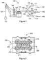
- Figure 1 shows a schematic side view representation of a load-bearing apparatus 100 according to a first embodiment of the present invention.
- the exemplary load-bearing apparatus 100 of Figure 1 reflects an offshore application such as an off-shore platform or vessel.
- the load-bearing apparatus 100 may equally find use in other applications, for example cranes such as off-shore on on-land cranes; towing systems; weight, counterweight, or cantilever devices; tension controlling devices; structural applications such as station keeping or any other structural applications requiring dynamic positioning and/or tensioning of a structure; or the like.
- the load-bearing apparatus 100 comprises a winch apparatus 110.
- the load-bearing apparatus 100 also comprises a load-bearing spoolable medium 120 for connecting to a load 130.
- the load-bearing spoolable medium 120 is shown in schematic form in Figures 1 and 2 for ease of reading.
- the load-bearing spoolable medium 120 comprises a plurality of load-bearing elements 121,122,123, best shown in figures 3 and 4 .
- the plurality of load-bearing elements comprises three load-bearing elements 121,122,123.
- a portion of the load-bearing spoolable medium 120 is spooled about the winch apparatus 110.
- the winch apparatus 110 is configured to control paying out and/or paying in of the load-bearing spoolable medium 120.
- the winch apparatus 110 is configured to function as a detensioning device to reduce tension within the load-bearing spoolable medium 120.
- the load-bearing spoolable medium 120 defines an outboard or high tension portion 125, between the load 130 and the winch apparatus 110, and defines an inboard or low tension portion 126, on a side of the winch apparatus 110 opposite the load 130.
- the load-bearing spoolable medium 120 and the winch apparatus 110 are described in more detail with reference to Figures 2 , 3 and 4 .
- the load-bearing apparatus 100 includes an overboarding assembly 140 which is used to appropriately direct a spoolable medium 120 from a vessel (not shown) into the sea. Additionally, a heave compensator 142 is provided which provides dynamic compensation to the spoolable medium 120 to accommodate for heaving motion of the associated vessel.
- the load-bearing apparatus 100 comprises a guide 144 for guiding each of the load-bearing elements 121,122,123 towards a respective tension control apparatus 151,152,153.
- the tension control apparatuses 151,152,153 are provided to control, apply and/or adjust the tension of a respective load-bearing element 121,122,123, on an inboard portion 126 thereof.
- the tension control apparatus 151,152,153 is further described in more detail with reference to Figures 5 and 6 .
- the load-bearing apparatus 100 further includes a storage apparatus 161,162,163, which in this embodiment is provided in the form of a plurality of storage baskets 161,162,163, which permit a respective load-bearing element 121,122,123 to be stored in a zero or near zero tension state.
- FIG 2 shows a load-bearing apparatus 200 according to a second embodiment of the present invention, showing load-bearing spoolable medium 220 and winch apparatus 210.
- the load-bearing spoolable medium 220 and winch apparatus 210 are generally similar to the load-bearing spoolable medium 120 and winch apparatus 110 of Figure 1 , like part denoted by like numerals, incremented by '100'.
- the winch apparatus 210 has a contact surface 211 configured for engaging the load-bearing spoolable medium 220.
- load-bearing spoolable medium 220 comprises a plurality of load-bearing elements arranged side-by-side on contact surface 211 of the winch apparatus 210.
- the contact surface 211 of the winch apparatus 210 comprises a plurality of circumferentially arranged support elements 212 or slats each having discrete contact surfaces which collectively define a drum contact surface.
- FIG 3 shows a load-bearing apparatus 300 according to a third embodiment of the present invention, showing load-bearing spoolable medium 320 and winch apparatus 310.
- the load-bearing spoolable medium 320 and winch apparatus 310 are generally similar to the load-bearing spoolable medium 120 and winch apparatus 110 of Figure 1 , like part denoted by like numerals, incremented by '200'.
- the contact surface 311 of the winch apparatus 310 comprises a substantially continuous, flat, surface 313.
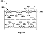
- FIG 4 shows a load-bearing apparatus 400 according to a fourth embodiment of the present invention, showing load-bearing spoolable medium 420 and winch apparatus 410.
- the load-bearing spoolable medium 420 and winch apparatus 410 are generally similar to the load-bearing spoolable medium 420 and winch apparatus 410 of Figure 1 , like part denoted by like numerals, incremented by '300'.
- the contact surface 411 of the winch apparatus 410 comprises a grooved surface having groove 414.
- the groove 414 is arranged to receive and guide the plurality of load-bearing elements 421,422,423 on the contact surface 411 as the load-bearing elements 421,422,423 are wound about the winch apparatus 410.
- the load-bearing spoolable medium 320,420 comprises three separate, distinct load-bearing elements 321,322,323 and 421,422,423 arranged side-by-side. Provision of a plurality of load-bearing elements 121,122,123, 321,322,323 and 421,422,423 arranged side-by-side permits reduction of a diameter of each of the load-bearing elements 121,122,123, 321,322,323 and 421,422,423 compared to a diameter of a corresponding single load-bearing medium that would be required to support the same load 130.
- each load-bearing element 321,322,323 and 421,422,423 comprises a synthetic fibre rope.
- the provision of three load-bearing elements significantly reduces the diameter appropriate for the winch apparatus 310,410, while maintaining the number of load-bearing elements relatively low to minimise difficulty of handling or risks of malfunction associated with a multiple rope system.
- a standard 136mm diameter single rope having a minimum break load (MBL) of 1125Te would give a safety factor of 4.5.
- each of the three load-bearing elements 321,322,323 and 421,422,423 of Figures 3 and 4 may have a diameter in the region of 70-90 mm, e.g. approximately 78 mm. This reduced diameter in each of the load-bearing elements allows reduction in he diameter of the associated winch apparatus 310,410.
- each of the two load-bearing elements may have a diameter in the region of 80-100 mm, e.g. approximately 88 mm. This reduced diameter in each of the load-bearing elements allows reduction in he diameter of the associated winch apparatus 310,410.
- each of the four load-bearing elements may have a diameter in the region of 50-80 mm, e.g. approximately 66 mm. This reduced diameter in each of the load-bearing elements allows reduction in he diameter of the associated winch apparatus 310,410.
- FIGS 3 and 4 depict load-bearing elements 321,322,323 and 421,422,423 having a substantially circular cross-section. However, this is for ease of representation only, and other rope profiles may be equally suitable for use in the present invention, such as flat ropes, or the likes.
- the load-bearing elements 321,322,323 and 421,422,423 are substantially parallel to each other on the contact surface 311,411 of the winch apparatus 310,410, in a plane substantially parallel to an axis of rotation 315,415 of the winch apparatus 310,410, and tangential to the contact surface 311,411.
- the load-bearing spoolable medium 320,420 defines three turns around the winch apparatus 310,410. It will be understood that the load-bearing spoolable medium 320,420 may define fewer, or more, turns, but only three turns are shown in Figures 3 and 4 for ease of understanding.
- the load-bearing elements 321,322,323 and 421,422,423 are provided in sequential order around the contact surface 311,411 of the winch apparatus 310,410. That is, each of the first, second and third turns (represented respectively by suffix a,b,c) defines in sequential order first, second and third load-bearing elements 321,322,323 and 421,422,423. A turn of a load-bearing element may be separated from an adjacent turn of the same load-bearing element, by the remaining load-bearing elements.
- first load-bearing element 321a,421a of the first turn is separated from first load-bearing element 321b,421b of the second turn by second and third load-bearing elements 322a,323a,422a,423a of the first turn.
- first load-bearing element 321b,421b of the second turn is separated from first load-bearing element 321c,421c of the third turn by second and third load-bearing elements 322b,323b,422b,423b of the second turn.
- the diameter of each of the plurality of load-bearing elements 321,322,323 and 421,422,423 is identical.
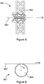
- FIG 5 is a side view of a tension control apparatus 551 according to a fifth embodiment of the present invention.
- the tension control apparatus 551 is generally similar to the tension control apparatus 151,152,153 of Figure 1 , like part denoted by like numerals, incremented by '400'.
- the tension control apparatus 551 comprises a tension control device 552 for engaging load-bearing element 521.
- the tension control device 552 is in the form of a track tensioner.
- FIG 6 is a side view of a tension control apparatus 651 according to a sixth embodiment of the present invention.
- the tension control apparatus 651 is generally similar to the tension control apparatus 151,152,153 of Figure 1 , like part denoted by like numerals, incremented by '500'.
- the tension control apparatus 651 comprises a tension control device 652 for engaging load-bearing element 621.
- the tension control device 652 is in the form of a drum, winch or sheave.
- each tension control apparatus 151,152,153 is provided to control, apply and/or adjust the tension of a respective load-bearing element 121,122,123, on an inboard portion 126 thereof.
- the tension control apparatus 151,152,153 are arranged to maintain a difference in tension between the load-bearing elements 121,122,123 at a predetermined level, e.g. below an upper limit such as below about 20%, e.g. below about 10%, e.g. below about 5%.
- the tension control apparatus 151,152,153 are configured to maintain or apply different tensions between the load-bearing elements. This may help accommodate, for example, operational or environmental requirements, fatigue or wear of one or more load-bearing elements, etc.
- each tension control apparatus 151,152,153 comprises a respective sensing device 155,156,157 which is arranged to measure the tension of a respective load-bearing element 121,122,123 on an inboard portion 126 thereof.
- each tension control apparatus 151,152,153 comprises a respective actuator 171,172,173, which in this embodiment forms part of a respective tension control device 151,152,153, and comprises a motor.
- each load-bearing element 121,122,123 may be individually and independently controlled, which may allow the apparatus 100 and/or a user to apply a desired tension on a outboard portion 125 of each load-bearing element 121,122,123.
Landscapes
- Engineering & Computer Science (AREA)
- Mechanical Engineering (AREA)
- Support Of The Bearing (AREA)
- Jib Cranes (AREA)
- Earth Drilling (AREA)
Description
- The present invention relates to a load-bearing apparatus comprising multiple load-bearing elements, to a traction device for use in such, and to a tension control apparatus for controlling the tension of each of the load-bearing elements.
- Numerous fields of application require the deployment of heavy loads to/from a location of interest, including building, construction, mining, oil and gas, etc. One such application involves the deployment of sub-sea hardware in very deep water, e.g., at depths of 1000m and greater. Deep water deployment of sub-sea hardware is particularly associated with the oil and gas industry. Examples of such sub-sea hardware include manifolds, templates, processing modules and wellhead systems. Assemblies of this type can weigh hundreds of tonnes. Similarly, extreme loads may be encountered when lifting or lowering a pipeline or section of pipeline to or from the seabed during installation and/or maintenance.
- Deep water deployment systems including cranes employ a variety of mechanisms and typically include traction systems to move payloads via load-bearing spoolable media, such as metal, synthetic or natural fibre cables, wires and ropes. Traction systems include a drum winch around which a spoolable medium is wound, wherein rotation of the drum permits spooling of the medium.
- In some species of winch the drum acts to store the spoolable medium, with the medium be arranged in single or multiple wraps and layers between end flanges of the drum. In such winch species, however, the spoolable medium may be subject to significant radial crushing forces, particularly in circumstances where large payloads are involved and thus significant tensions are applied to the spoolable medium. Further, in some applications it may be necessary to store the medium in a high tension state, which may reduce the life span of the medium through fatigue, excessive strains, hysteresis and the like. Furthermore, storage of the spoolable medium on a drum typically requires the use of complex fleeting arrangements to ensure that the medium is arranged in suitable wraps and layers.
- In other species of winch the drum is used only to apply a force to a spoolable medium, with the spoolable medium being stored separately, for example in a basket, on a separate spool or the like. The force applied by the drum is typically either a pulling force to pay in a spoolable medium, or a controlled releasing force to permit controlled paying out of a spoolable medium while under load, for example while connected to a payload. In such winch species, which may include capstan or windlass winches, an intermediate portion of a spoolable medium is wrapped around the drum a number of times such that an outboard side of the spoolable medium extends from the drum to engage a payload, and an inboard side of the spoolable medium extends to storage. Under loaded conditions the drum functions to reduce the tension in the spoolable medium from a high tension condition in the outboard side, to a lower tension condition in the inboard side of the spoolable medium, thus permitting the spoolable medium to be stored in a favourable low tension state. In view of this tension reduction functionality, such winch species are often called detensioning units. In use, the drum establishes a tension gradient in the spoolable medium, which may be defined by the capstan friction equation:

- T1 = outboard tension
- T2 = inboard tension
- µ = co-efficient of friction between the spoolable medium and the drum or contact surface
- θ = angle of contact with the drum (e.g., one wrap is 2π radians)
- The traction winch may include multiple sheaves over which the rope is drawn both to provide adequate traction and to progressively unload the rope before it is passed to the storage take up reel at low tension. An example of such traction winch is disclosed in
U.S. Patent No. 6,182,915 (ODIM HOLDING ASA) in which the multiple sheaves are separately powered in a manner to prevent the cable from being damaged by slipping as it unloads. Another example is disclosed in International Patent Application Publication No.WO 2011/121272 (PARKBURN PRECISION HANDLING SYSTEMS LTD) in which two traction winch drums configured to rotate about respective first and second axes of rotation which are inclined relative to each other. The relative inclined alignment of the first and second axes of rotation of the drum assemblies permits the respective drum contact surfaces to cooperate to manipulate an associated spoolable medium to follow a predefined path, such as a predefined helical path. - When steel is used as a spoolable medium, the deployment of very large loads of the type described above requires the use of very large steel wire ropes or cables. However, especially at great depths, the weight of the steel itself becomes a significant problem. Not only does this impose tremendous loads on the lifting system but also, beyond a certain depth, it becomes impossible to make a wire rope large enough to support its own weight without exceeding its safe working loads, let alone the weight of the equipment to which it is attached.
- In order to reduce the weight of the spoolable media used in very deep water applications, synthetic fibre ropes have been adopted. Synthetic fibre ropes typically exhibit near neutral buoyancy and therefore minimal added weight, even when working at great depths. Such ropes can be made from a variety of synthetic fibres. Ultra High Molecular Weight Polyethylene (UHMWPE) fibre rope has proven especially successful due to its high strength to weight ratio and low elongation under loads. For example, suitable UHMWPE fibre ropes are available under the Dyneema® trademark of DSM, The Netherlands.
- Although synthetic fibre ropes offer a viable solution for deep water deployment, and are vastly superior to steel wire rope in many respects, they nevertheless present special challenges of their own, especially when used in larger diameters. In particular, when used with traction winches, synthetic fibre ropes typically require larger diameter sheave wheels than do wire ropes. A number of reasons for this may include (among others) the susceptibility of individual fibres to fracture when bent and also the relative inability of the fibre material to shed heat due to its low thermal conductivity, which can in turn lead to heat build-up and damage to the fibres in the core of the rope. As a result, it has been determined that the practical minimum "D:d" diameter ratio for using large synthetic fibre ropes on traction winch systems is approximately 30:1, wherein "D:d" represents the ratio between the diameter of the sheave wheel and the diameter of the rope. Current research focusing on loads of 250Te indicates that a synthetic fibre rope having the requisite capacity (including industry established safety margins) will have a diameter on the order of 140mm. Based on the minimum 30:1 ratio, the corresponding minimum sheave diameter is approximately 4.2m, which is very large. A 750Te system would require a proportionately larger rope, to the point where the sheave wheels and associated machinery would be prohibitively large. Not only is the cost of such equipment very high, but it is compounded by the need to use a larger vessel and a larger crew, to the point where feasibility is drawn into question.
- Furthermore, very large diameter synthetic ropes present additional problems. In particular, ropes do not scale well and suffer a loss of strength translation efficiency in their larger sizes. Furthermore, it has been found that, even when using optimally-sized sheaves, the larger the rope the lower the number of bend cycles it is able to sustain before failure. Although the reasons for this are not entirely clear, and without wishing to be bound by theory, it is believed that this may be primarily due to the mass of material involved and the impact of the heat and abrasion generated by the greater number of crossover points within the rope structure, complicated by the insulation efficiency of the fibre material. Yet another difficulty is that splices or other repairs in large-size synthetic ropes increase diameter, which makes it very difficult for these to pass through the grooves of conventional sheave wheels, particularly on the leading sheave wheel where the rope is under extreme tension.
- Systems using multi fall arrangements have been used in the past to seek to overcome some of the limitations cited above, and have been used with both steel wire and fibre rope systems. However, although this technique overcomes the need for large diameter ropes, some limitations of this approach include reduction of deployment speed by a factor proportionate to the number of falls in the moving block. This creates a significant increase in deployment time and hence results in a high cost impact when deploying payloads in great water depths. This also creates difficulty achieving sufficient speed in the lifting line when employing active heave compensation required for decoupling the vessel motions from the payload during deployment.
- Systems using multiple separate drum winch systems with single lift lines connected to the payload have been used with some success to overcome these issues. However, the challenge of controlling multiple systems and balancing high tension loads in each of the lifting wires is a significant challenge, and the risks involved if precise control is not maintained between the separate winch systems make this technique difficult to implement.
- Various arrangements of multiple ropes or cables combined with one or more drums are disclosed in
EP 1 460 025 (StrOdter),US 605,937 (Turner),US 6,042,087 (Heinemann),US 4,600,086 (Yamasaki et al. ),JP 11-011882 JP 07196288 SU 412133 CN 201220899 Weihua Group). -
EP 0 699 618 discloses a clamping device for an artificial fibre rope, especially for use in lifts. It comprises a retainer drum with at least one cut-in rope for accommodation of the rope. -
JP H11 11822 -
SU 724 433 -
DE 195 25 921 discloses a method for winding tethers in several cable layers on a cable drum and a hoist. -
GB 2 155 904 -
WO 2011/121272 discloses a winch apparatus comprising first and second drum assemblies each defining a discontinuous drum contact surface. -
WO 2007/127453 discloses a lift assembly system and method including a substantially rectangular tube, a motor operably connected to first and second drives, a rotatable drum and, structurally connected to one end of the tube, a head block. -
US 3 306 580 discloses a pair of conductors wound on drums provided with double helical grooves. -
WO 2009/078044 discloses a synchronization device, plant and machines for laying cables such as electric conductors, optical fibres, ropes and the like. - The invention is a load-bearing apparatus according to claim 1 and a method for bearing a load according to claim 14.
- In what follows non-claimed examples are presented which are useful for understanding the invention.
- According to a first example there is provided a load-bearing apparatus comprising:
- a detensioning winch apparatus defining an outboard side and an inboard side; and
- a load-bearing spoolable medium for connecting to a load, the load-bearing spoolable medium comprising a plurality of load-bearing elements;
- wherein at least a portion of the load-bearing spoolable medium is spooled about the winch apparatus.
- The winch apparatus may comprise a contact surface for engaging at least a portion of the load-bearing medium, e.g. at least a portion of the plurality of load-bearing elements, e.g. at least a portion of each of the plurality of load-bearing elements.
- The winch apparatus may be configured to control paying out and/or paying in of the plurality of load-bearing elements. The winch apparatus may be configured to control paying out and/or paying in of each of the plurality of load-bearing elements simultaneously.
- The winch apparatus may be configured to function as a detensioning device for use in reducing tension within the load-bearing medium. As such, the winch apparatus may comprise or define a detensioning device.
- The winch apparatus may be configured as a capstan winch.
- The load-bearing spoolable medium may comprise an outboard or high tension portion, between the load and the winch apparatus.
- The load-bearing spoolable medium may comprise an inboard or low tension portion, on a side of the winch apparatus opposite the load.
- The winch apparatus may comprise an outboard or high tension side, between the load and the winch apparatus.
- The winch apparatus may comprise an inboard or low tension side, on a side of the winch apparatus opposite the load.
- One or more load-bearing elements may comprise an elongate element, such as a rope, cable, wire, or the like.
- One or more load-bearing elements may comprise a multicomponent element, such as a rope, cable, wire, or the like.
- One or more load-bearing elements may comprise a synthetic fibre rope, a metal rope such as a steel rope, or the like.
- The cross-section of one or more load-bearing elements may be substantially circular, oval, rectangular (e.g. a so-called "flat rope), or may have any other suitable profile.
- One or more load-bearing elements may be made from a polymeric material, for example UHMWPE such as sold under the trade names of DYNEEMA® and
a load-bearing spoolable medium for connecting to a load on the outboard side of the detensioning winch apparatus, the load-bearing spoolable medium comprising a plurality of load-bearing elements and being spooled for at least one turn about the detensioning winch apparatus and defining an outboard portion extending on the outboard side of the detensioning winch apparatus and an inboard portion extending on the inboard side of the detensioning winch apparatus;
a tension control apparatus for individually and adjustably controlling the tension of each of the plurality of load-bearing elements;
wherein the load bearing elements are arranged side-by-side on a contact surface of the detensioning winch apparatus;
wherein the detensioning winch apparatus reduces tension within the load-bearing spoolable medium from the outboard portion to the inboard portion. - The winch apparatus may comprise a contact surface for engaging at least a portion of the load-bearing medium, e.g. at least a portion of the plurality of load-bearing elements, e.g. at least a portion of each of the plurality of load-bearing elements.
- The winch apparatus may be configured to control paying out and/or paying in of the plurality of load-bearing elements. The winch apparatus may be configured to control paying out and/or paying in of each of the plurality of load-bearing elements simultaneously.
- The winch apparatus may be configured to function as a detensioning device for use in reducing tension within the load-bearing medium. As such, the winch apparatus may comprise or define a detensioning device.
- The winch apparatus may be configured as a capstan winch.
- The load-bearing spoolable medium may comprise an outboard or high tension portion, between the load and the winch apparatus.
- The load-bearing spoolable medium may comprise an inboard or low tension portion, on a side of the winch apparatus opposite the load.
- The winch apparatus may comprise an outboard or high tension side, between the load and the winch apparatus.
- The winch apparatus may comprise an inboard or low tension side, on a side of the winch apparatus opposite the load.
- One or more load-bearing elements may comprise an elongate element, such as a rope, cable, wire, or the like.
- One or more load-bearing elements may comprise a multicomponent element, such as a rope, cable, wire, or the like.
- One or more load-bearing elements may comprise a synthetic fibre rope, a
metal rope such as a steel rope, or the like. - The cross-section of one or more load-bearing elements may be substantially circular, oval, rectangular (e.g. a so-called "flat rope), or may have any other suitable profile. One or more load-bearing elements may be made from a polymeric material, for example UHMWPE such as sold under the trade names of DYNEEMA® and
- The load-bearing medium may comprise a plurality of separate and/or distinct load-bearing elements. It will be understood that the terms "separate and distinct" are not meant to limit the configuration of the load-bearing elements relative to each other, i.e. the load-bearing elements may be in contact, or may not be in contact, with each other. Thus, the terms "separate and distinct" are meant to indicate that the load-bearing elements each support, e.g. independently, a proportion, e.g. a predetermined amount or proportion of the weight of the load. By such provision, a dimension, e.g. a diameter, of each of the load-bearing elements may be reduced compared to a dimension, e.g. diameter, of a corresponding single load-bearing medium that would be required to support the same load. One of the effects and advantages of such reduction in diameter of the load-bearing elements is that the diameter of a winch used with such load-bearing elements may be reduced. Winch systems typically have an optimum diameter based on the diameter of the spoolable medium used. Therefore, reduction in the diameter of the load-bearing elements may allow significant reduction in the diameter of the winch apparatus, e.g. a drum thereof.
- The load-bearing spoolable medium may comprises a plurality of adjacent load-bearing elements.
- The load-bearing elements may be arranged side-by-side on the winch apparatus, e.g. on a contact surface of the winch apparatus.
- The load-bearing elements may be arranged in a common plane.
- The load-bearing elements may be arranged on the winch apparatus in a plane being generally in a direction of, or parallel to, an axis, e.g. to a rotational axis, of the winch apparatus.
- The load-bearing elements, e.g. the adjacent and/or side-by-side load-bearing elements, may be substantially parallel to each other, e.g. when in engagement with the contact surface of the winch apparatus. The load-bearing elements may be substantially parallel to each other when in engagement with the contact surface of the winch apparatus, in a plane substantially parallel to an axis, e.g. to an axis of rotation, of the winch apparatus, and/or tangential to a surface of the winch apparatus.
- The load-bearing elements, e.g. an outboard portion thereof, may be substantially parallel to each other.
- The load bearing spoolable medium may define one or more turns around the winch apparatus.
- Typically, the load bearing spoolable medium may define a plurality of turns around the winch apparatus.
- The load-bearing elements may be provided in sequential order around or about the winch apparatus. A turn of a load-bearing element may be separated from an adjacent turn of the same load-bearing element, by the remaining load-bearing elements. Each turn of the load bearing spoolable medium may comprise a turn of the load-bearing elements provided in sequential order on the winch apparatus.
- The weight of the load may be distributed amongst the plurality of load-bearing elements.
- In one embodiment, the weight of the load may be substantially evenly distributed amongst the plurality of load-bearing elements.
- In another embodiment, the weight of the load may be unevenly distributed amongst the plurality of load-bearing elements. For example, one or more load-bearing elements may be selected to bear a higher or lower load compared to the other load-bearing elements, e.g. temporarily, in order to accommodate, for example, operational or environmental requirements, fatigue or wear of one or more load-bearing elements, etc.
- A dimension, e.g. a diameter, of two or more load-bearing elements, may be substantially identical.
- Two or more of the plurality of load-bearing elements may have a different dimension, e.g. diameter, from a dimension, e.g. diameter, of at least another one or more of the plurality of load-bearing elements.
- The term "diameter" used herein is not meant to limit the profile of the load-bearing elements to a particular profile, such as circular in cross-section, but is meant to refer to a general height and/or width of a cross-section of the load-bearing elements.
- The load may comprise a single load. In such instance each of the plurality of load-bearing elements may be configured for supporting, connecting to and/or attaching to a single load. By such provision, a dimension, e.g. a diameter, of each of the load-bearing elements may be reduced compared to a dimension, e.g. diameter, of a corresponding single load-bearing medium that would be required to support the same load. This may allow significant reduction in the diameter of a winch apparatus, , e.g. a drum thereof, to be used with such load-bearing elements.
- The at least one load may comprise a plurality of loads. In one embodiment, each of the plurality of load-bearing elements may be configured for supporting, connecting to and/or attaching to a respectively load. By such provision, the load-bearing apparatus may allow deployment and/or handling of multiple loads using a single winch apparatus. This may be particularly advantageous, e.g. when a plurality of similarly weighed objects required to be lowered/hoisted/supported to/from/at a given location, for example sections of tubing or casing, manifolds, etc.
- Various combinations of the above may be envisaged. For example, one of the plurality of load-bearing elements may be connected to a load of relatively low weight, while several of the plurality of load-bearing elements may be connected to a load of relatively high weight.
- The contact surface of the winch apparatus configured for engaging the load-bearing spoolable medium and/or the plurality of load-bearing elements, may comprise a substantially flat surface.
- The contact surface of the winch apparatus may comprise a substantially continuous surface, e.g. a drum surface. The contact surface of the winch apparatus may comprise an interrupted surface, e.g. may be defined by a plurality of support elements, e.g. plurality of circumferentially arranged support elements which may collectively define a/the contact surface.
- The contact surface may comprise a grooved profile, e.g. may comprise at least one groove. In one embodiment the at least one groove may be arranged to receive and/or guide the load-bearing spoolable medium and/or the plurality of load-bearing elements on the contact surface.
- The winch apparatus may comprise one or more sheaved wheels, a single drum winch, a multiple drum winch, or the like.
- The load-bearing apparatus may comprise a tension control apparatus for controlling, applying and/or adjusting the tension of the load-bearing spoolable medium and/or the plurality of load-bearing elements, e.g. on an inboard or low tension side of the winch apparatus.
- The tension control apparatus may be located on an inboard side of the winch apparatus.
- The tension control apparatus may be arranged to individually and/or independently control, apply, and/or adjust the tension of each of the plurality of load-bearing elements.
- The tension control apparatus may comprise at least one tension control device.
- The tension control apparatus may comprise one tension control device capable of controlling, applying and/or adjusting the tension of each of the plurality of load-bearing elements.
- The tension control apparatus may comprise a plurality of tension control devices, each capable of controlling, applying and/or adjusting the tension of a respective load-bearing element, e.g. individually and/or independently. By such provision, any variation in tension between load-bearing elements on an outboard side of the winch apparatus, e.g. due to marine currents, interfering objects, rope construction, etc, may be mitigated and/or overcome by controlling and/or adjusting the tension of each of the load-bearing elements on an inboard side of the winch apparatus. This is because the tension gradient on the winch apparatus may be defined by the capstan friction equation:

- T1 = outboard tension
- T2 = inboard tension
- µ = co-efficient of friction between the load-bearing element and the drum or contact surface
- θ = angle of contact with the drum or contact surface (e.g., one wrap is 2π radians)
- Therefore, assuming that µ and θ are known, T1 on the outboard side can be controlled and/or maintained at a predetermined or desired value by controlling and/or maintaining T2 on the inboard side at a predetermined value.
- In one embodiment, the at least one tension control apparatus may be configured to maintain or apply substantially equal tensions between the load-bearing elements, e.g. when the load-bearing elements are of substantially equal dimension, e.g. diameter. The at least one tension control apparatus may be configured to maintain or apply substantially equal tensions between respective outboard portions of the plurality of load-bearing elements. By such provision, the weight of the at least one load may be substantially equally distributed amongst the load-bearing elements, thus preventing any of the ropes from experiencing overload that may lead to premature failure. This may also ensure compliance within a minimum safety standards in the industry. Offshore lifting operations are regulated by classification society rules and regulations, which include for example DNV, Bureau Veritas and Lloyds Register. All lifting and lowering operations have to maintain a certain minimum safety factor (SF) within the lifting system related to a payload, the SF including not only the weight in air but any added mass or other dynamic factors the payload will see during deployment. Typical minimum SF for offshore operations is in the order of 3.5 x the payload. Thus, controlling the inboard tension of each load-bearing element to maintain substantially equal outboard tensions between the plurality of load-bearing elements, may assist in complying with minimum safety regulations in a particular industry, such as offshore lifting operations. Another advantage may include reducing the difference in load elongation between the load-bearing elements, which may lead to undesirable relative movement or slip between the load-bearing elements on the winch apparatus.
- In another embodiment, the at least one tension control apparatus may be configured to maintain or apply different tensions between the load-bearing elements. The at least one tension control apparatus may be configured to maintain or apply different tensions between respective outboard portions and/or inboard portions of the plurality of load-bearing elements. This may help accommodate, for example, operational or environmental requirements, fatigue or wear of one or more load-bearing elements, etc.
- Various combinations of the above may be envisaged. For example, the at least one tension control apparatus may be configured to maintain or apply substantially equal tensions between two or more of the load-bearing elements, and may be configured to maintain or apply different tensions between two or more of the load-bearing elements.
- The tension control apparatus may be arranged to maintain a difference in tension between the load-bearing elements at a predetermined level, e.g. below a predetermined limit, such as below about 20%, e.g. below about 10%, e.g. below about 5%. The tension control apparatus may be arranged to maintain a difference in tension between the load-bearing elements at a particular or predetermined position relative to the winch apparatus, e.g. on an outboard side and/or on an inboard side thereof.
- The tension control device(s) may comprise at least one drum, winch, sheave, track system, or the like.
- The load-bearing apparatus, e.g. the tension control apparatus, may comprise a sensing device or arrangement.
- The sensing device or arrangement may be arranged to sense or measure at least one property or parameter of at least one portion of the load-bearing apparatus. The sensing device or arrangement may be arranged to sense or measure at least one property or parameter of the load-bearing spoolable medium.
- The sensing device or arrangement may comprise at least one tension-measuring device, e.g. meter, for measuring the tension of one or more load-bearing elements, e.g. of the plurality of load-bearing elements, e.g. on an inboard portion thereof.
- In one embodiment, the sensing device or arrangement may comprise a plurality of tension-measuring devices, each capable of measuring the tension of a respective load-bearing element, e.g. on an inboard portion thereof.
- The sensing device or arrangement may comprise a sensor associated with the winch apparatus, e.g. a rotational sensor.
- The sensing device or arrangement may comprise a sensor for measuring the deviation or movement of the load-bearing elements on the winch apparatus, e.g. on a drum thereof.
- The sensing device or arrangement may comprise a sensor for measuring the length of rope provided engaging the winch apparatus, e.g. a contact surface thereof. By such provision, any slip of one or more load-bearing elements on the winch apparatus, e.g. due to excessive tension, may be detected.
- The load-bearing apparatus, e.g. the tension control apparatus, may comprise at least one actuator, e.g. a tension control actuator. The at least one actuator, e.g. tension control actuator, may be arranged for actuating the at least one tension control device, or may form part of the at least one tension control device.
- The at least one actuator may comprise a motor.
- In one embodiment, the load-bearing apparatus, e.g. the tension control apparatus, may comprise a plurality of actuators, each capable of actuating a respective tension control device.
- The sensing device or arrangement may be arranged to provide feedback, e.g. to a user or operator, and/or may comprise a closed-loop control system, e.g. a closed-loop tension control apparatus.
- The sensing device or arrangement may be provided with a display, e.g. a graphic, alphanumeric, audio, and/or tactile display, arranged to provide feedback, e.g. an indication of a measurement made by the sensing device or arrangement.
- The at least one actuator may be activated manually, e.g. by a user, for example in response to a measurement made by the sensing device or arrangement, such as a change in tension measured by the at least one tension-measuring device.
- The at least one actuator may be activated automatically and/or may form part of a closed-loop system, e.g. a closed-loop tension control apparatus. In one embodiment, the at least one actuator may be associated with the at least one tension-measuring device, such that departure in tension from a predetermined range may automatically activate the at least one actuator, and/or cause the at least one actuator to actuate the at least one tension control device.
- The load-bearing apparatus may further comprise a storage apparatus for storing the load-bearing medium.
- The storage apparatus may be provided on an inboard side of the winch apparatus, e.g. on an inboard side of the tension control apparatus.
- The storage apparatus may comprise one or more storage devices.
- In one embodiment, the storage apparatus may comprise one storage device capable of storing the load-bearing spoolable medium, e.g. the plurality of load-bearing elements.
- In another embodiment, the storage apparatus may comprise a plurality of storage devices, each capable of storing a relative load-bearing element.
- The storage apparatus may comprise one or more container, reel, or the like.
- The load-bearing apparatus may be used in applications requiring supporting or moving, e.g. lowering or hoisting, of a load. Such applications may comprise subsea applications, such as on off-shore platforms or vessels; cranes such as off-shore on on-land cranes; towing systems; weight, counterweight, or cantilever devices; tension controlling devices; or the like.
- According to a second example there is provided a load-bearing apparatus comprising:
- a winch apparatus; and
- a load-bearing spoolable medium for connecting to a load, the load-bearing medium comprising a plurality of load-bearing elements;
- wherein at least a portion of the load-bearing spoolable medium is spooled about the winch apparatus;
- wherein the load-bearing elements are arranged side-by-side on a contact surface of the winch apparatus.
- At least a portion of the load-bearing spoolable medium may be spooled about a contact surface of the winch apparatus.
- The load-bearing medium may comprises a plurality of adjacent load-bearing elements.
- The load-bearing elements may be arranged side-by-side on the winch apparatus, e.g. on a contact surface of the winch apparatus.
- The load-bearing elements may be arranged in a common plane.
- The load-bearing elements may be arranged on the winch apparatus in a plane being generally in a direction of an axis, e.g. of a rotational axis, of the winch apparatus.
- The load-bearing elements, e.g. the adjacent and/or side-by-side load-bearing elements, may be substantially parallel to each other, e.g. when in engagement with the contact surface of the winch apparatus. The load-bearing elements may be substantially parallel to each other when in engagement with the contact surface of the winch apparatus, in a plane substantially parallel to an axis, e.g. to an axis of rotation, of the winch apparatus.
- The features described in respect of the load-bearing apparatus according to a first example may apply in respect of the load-bearing apparatus according to a second aspect of the present invention, and are therefore not repeated here for brevity.
- According to a third example there is provided a winch apparatus comprising a contact surface configured for engaging a load-bearing spoolable medium comprising plurality of load-bearing elements arranged side-by-side on a contact surface of the winch apparatus.
- The plurality of load-bearing elements may collectively define a load-bearing spoolable medium.
- The plurality of load-bearing elements may be adapted to support, connect to and/or attach to a load.
- The winch apparatus may be configured to control paying out and/or paying in of the plurality of load-bearing elements. The winch apparatus may be configured to control paying out and/or paying in of each of the plurality of load-bearing elements simultaneously.
- The winch apparatus may be configured to function as a detensioning device for use in reducing tension within the load-bearing medium. As such the winch apparatus may comprise or define a detensioning device.
- The winch apparatus may be configured as a capstan winch.
- The winch apparatus may comprise an outboard or high tension side, between the load and the winch apparatus.
- The winch apparatus may comprise an inboard or low tension side, on a side of the winch apparatus opposite the load.
- The contact surface of the winch apparatus may be configured for engaging a plurality of adjacent load-bearing elements.
- The contact surface of the winch apparatus may be configured for engaging a plurality of load-bearing elements which may be substantially parallel to each other, at least when in engagement with the contact surface of the winch apparatus. The load-bearing elements may be substantially parallel to each other when in engagement with the contact surface of the winch apparatus, in a plane substantially parallel to an axis of rotation of the winch apparatus. The load-bearing elements may be substantially parallel to each other on an outboard side of the winch apparatus.
- The contact surface of the winch apparatus may comprise a substantially flat surface.
- The contact surface of the winch apparatus may comprise a substantially continuous surface, e.g. a drum surface. The contact surface of the winch apparatus may comprise an interrupted surface, e.g. may be defined by a plurality of support elements, e.g. plurality of circumferentially arranged support elements which may collectively define a/the contact surface.
- The contact surface may comprise a grooved profile, e.g. may comprise at least one groove. In one embodiment the at least one groove may be arranged to receive and/or guide the plurality of load-bearing elements on the contact surface.
- The winch apparatus may comprise one or more sheaved wheels, a single drum winch, a multiple drum winch, or the like.
- The features described in respect of the load-bearing apparatus according to a first aspect or a second aspect of the present invention may apply in respect of the winch apparatus according to a third aspect of the present invention, and are therefore not repeated here for brevity.
- According to a fourth example there is provided a plurality of load-bearing elements configured for connecting to a load at or near one end thereof, wherein the plurality of load-bearing elements is arranged side-by-side and is configured to engage a contact surface of a winch apparatus.
- The plurality of load-bearing elements may comprise an outboard or high tension portion, between the load and the winch apparatus.
- The plurality of load-bearing elements may comprise an inboard or low tension portion, on a side of the winch apparatus opposite the load.
- One or more load-bearing elements may comprise an elongate element, such as a rope, cable, wire, or the like.
- One or more load-bearing elements may comprise a multicomponent element, such as a rope, cable, wire, or the like.
- One or more load-bearing elements may comprise a synthetic fibre rope, a metal rope such as a steel rope, or the like.
- The cross-section of one or more load-bearing elements may be substantially circular, oval, rectangular (e.g. a so-called "flat rope), or may have any other suitable profile.
- The plurality of load-bearing elements may comprises a plurality of separate and/or distinct load-bearing elements. It will be understood that the terms "separate and distinct" are not meant to limit the configuration of the load-bearing elements relative to each other, i.e. the load-bearing elements may be in contact, or may not be in contact, with each other. Thus, the terms "separate and distinct" are meant to indicate that the load-bearing elements each support, e.g. independently, a proportion, e.g. a predetermined amount or proportion of the weight of the load. By such provision, a dimension, e.g. a diameter, of each of the load-bearing elements may be reduced compared to a dimension, e.g. diameter, of a corresponding single load-bearing medium that would be required to support the same load. One of the effects and advantages of such reduction in diameter of the load-bearing elements is that the diameter of a winch used with such load-bearing elements may be reduced. Winch systems typically have an optimum diameter based on the diameter of the spoolable medium used. Therefore, reduction in the diameter of the load-bearing elements may allow significant reduction in the diameter of the winch apparatus, e.g. a drum thereof.
- The plurality of load-bearing elements may comprise a plurality of adjacent load-bearing elements.
- The load-bearing elements may be arranged side-by-side on the winch apparatus, e.g. on a contact surface of the winch apparatus.
- The load-bearing elements may be arranged in a common plane.
- The load-bearing elements may be arranged on the winch apparatus in a plane being generally in a direction of an axis, e.g. to a rotational axis, of the winch apparatus.
- The load-bearing elements, e.g. the adjacent and/or side-by-side load-bearing elements, may be substantially parallel to each other, e.g. when in engagement with the contact surface of the winch apparatus. The load-bearing elements may be substantially parallel to each other when in engagement with the contact surface of the winch apparatus, in a plane substantially parallel to an axis, e.g. to an axis of rotation, of the winch apparatus.
- The load-bearing elements, e.g. an outboard portion thereof, may be substantially parallel to each other.
- The features described in respect of the load-bearing apparatus according to a first example or a second example may apply in respect of the plurality of load-bearing elements according to a fourth example and are therefore not repeated here for brevity.
- According to a fifth example there is provided a tension control apparatus for controlling, applying and/or adjusting the tension of a plurality of load-bearing elements engaging a contact surface of a winch apparatus, wherein the tension control apparatus is provided on an inboard or low tension side of the winch apparatus.
- The tension control apparatus may be arranged to individually and/or independently control, apply, and/or adjust the tension of each of the plurality of load-bearing elements.
- The tension control apparatus may comprise at least one tension control device.
- The tension control apparatus may comprise one tension control device capable of controlling, applying and/or adjusting the tension of each of the plurality of load-bearing elements.
- The tension control apparatus may comprise a plurality of tension control devices, each capable of controlling, applying and/or adjusting the tension of a respective load-bearing element. By such provision, any variation in tension between load-bearing elements on an outboard side of the winch apparatus, e.g. due to marine currents, interfering objects, rope construction, etc, may be mitigated and/or overcome by controlling and/or adjusting the tension of each of the load-bearing elements on an inboard side of the winch apparatus. This is because the tension gradient on the winch apparatus may be defined by the capstan friction equation:

- T1 = outboard tension
- T2 = inboard tension
- µ = co-efficient of friction between the load-bearing element and the drum or contact surface
- θ = angle of contact with the drum or contact surface (e.g., one wrap is 2π radians)
- Therefore, assuming that µ and θ are known, T1 on the outboard side can be controlled and/or maintained at a predetermined or desired value by controlling and/or maintaining T2 on the inboard side at a predetermined value.
- In one embodiment, the at least one tension control apparatus may be configured to maintain or apply substantially equal tensions between the load-bearing elements, e.g. when the load-bearing elements are of substantially equal dimension, e.g. diameter. The at least one tension control apparatus may be configured to maintain or apply substantially equal tensions between respective outboard portions of the plurality of load-bearing elements. By such provision, the weight of the at least one load may be substantially equally distributed amongst the load-bearing elements, thus preventing any of the ropes from experiencing overload that may lead to premature failure. This may also ensure compliance within a minimum safety standards in the industry. Offshore lifting operations are regulated by classification society rules and regulations, which include for example DNV, Bureau Veritas and Lloyds Register. All lifting and lowering operations have to maintain a certain minimum safety factor (SF) within the lifting system related to a payload, the SF including not only the weight in air but any added mass or other dynamic factors the payload will see during deployment. Typical minimum SF for offshore operations is in the order of 3.5 x the payload. Thus, controlling the inboard tension of each load-bearing element to maintain substantially equal outboard tensions between the plurality of load-bearing elements, may assist in complying with minimum safety regulations in a particular industry, such as offshore lifting operations. Another advantage may include reducing the difference in load elongation between the load-bearing elements, which may lead to undesirable relative movement or slip between the load-bearing elements on the winch apparatus.
- In another embodiment, the at least one tension control apparatus may be configured to maintain or apply different tensions between the load-bearing elements. The at least one tension control apparatus may be configured to maintain or apply different tensions between respective outboard portions of the plurality of load-bearing elements. This may help accommodate, for example, operational or environmental requirements, fatigue or wear of one or more load-bearing elements, etc.
- Various combinations of the above may be envisaged. For example, the at least one tension control apparatus may be configured to maintain or apply substantially equal tensions between two or more of the load-bearing elements, and may be configured to maintain or apply different tensions between two or more of the load-bearing elements.
- The tension control apparatus may be arranged to maintain a difference in tension between the load-bearing elements at a predetermined level, e.g. below a predetermined limit, such as below about 20%, e.g. below about 10%, e.g. below about 5%. The tension control apparatus may be arranged to maintain a difference in tension between the load-bearing elements at a particular position relative to the winch apparatus, e.g. on an outboard side and/or on an inboard side thereof.
- The tension control device(s) may comprise at least one drum, winch, sheave, track system, or the like.
- The load-bearing apparatus, e.g. the tension control apparatus, may comprise a sensing device or arrangement.
- The sensing device or arrangement may be arranged to sense or measure at least one property or parameter of at least one portion of the load-bearing apparatus. The sensing device or arrangement may be arranged to sense or measure at least one property or parameter of the load-bearing spoolable medium.
- The sensing device or arrangement may comprise at least one tension-measuring device, e.g. meter, for measuring the tension of the plurality of load-bearing elements, e.g. on an inboard portion thereof.
- In one embodiment, the sensing device or arrangement may comprise a plurality of tension-measuring devices, each capable of measuring the tension of a respective load-bearing element, e.g. on an inboard portion thereof.
- The sensing device or arrangement may comprise a sensor associated with the winch apparatus, e.g. a rotational sensor.
- The sensing device or arrangement may comprise a sensor for measuring the deviation or movement of the load-bearing elements on the winch apparatus, e.g. on a drum thereof.
- The sensing device or arrangement may comprise a sensor for measuring the length of rope provided engaging the winch apparatus, e.g. a contact surface thereof. By such provision, and slip of one or more load-bearing elements on the winch apparatus, e.g. due to excessive tension, may be detected.
- The load-bearing apparatus, e.g. the tension control apparatus, may comprise at least one actuator, e.g. a tension control actuator. The at least one actuator, e.g. tension control actuator, may be arranged for actuating the at least one tension control device, or may form part of the at least one tension control device.
- The at least one actuator may comprise a motor.
- In one embodiment, the load-bearing apparatus, e.g. the tension control apparatus, may comprise a plurality of actuators, each capable of actuating a respective tension control device.
- The sensing device or arrangement may be arranged to provide feedback to a user, and/or may comprise a closed-loop control system, e.g. a closed-loop tension control apparatus.
- The sensing device or arrangement may be provided with a display, e.g. a graphic, alphanumeric, audio, and/or tactile display, arranged to provide feedback, e.g. an indication of a measurement made by the sensing device or arrangement.
- The at least one actuator may be activated manually, e.g. by a user, for example in response to a measurement made by the sensing device or arrangement, such as a change in tension measured by the at least one tension-measuring device.
- The at least one actuator may be activated automatically and/or may form part of a closed-loop system, e.g. a closed-loop tension control apparatus. In one embodiment, the at least one actuator may be associated with the at least one tension-measuring device, such that departure in tension from a predetermined range may automatically activate the at least one actuator, and/or cause the at least one actuator to actuate the at least one tension control device.
- The features described in respect of the load-bearing apparatus according to a first aspect or second of the present invention may apply in respect of the tension control apparatus according to a fifth aspect of the present invention, and are therefore not repeated here for brevity.
- According to a sixth example there is provided a load-bearing apparatus comprising:
- a winch apparatus; and
- a load-bearing spoolable medium for connecting to a load on an outboard side of the winch apparatus, the load-bearing medium comprising a plurality of load-bearing elements, wherein at least a portion of the load-bearing spoolable medium is spooled about the winch apparatus, and wherein the load-bearing elements are arranged side-by-side on a contact surface of the winch apparatus; and
- a tension control apparatus for controlling, applying and/or adjusting the tension of the plurality of load-bearing elements on an inboard side of the winch apparatus.
- The features described in respect of any of the first to fifth aspects of the present invention may apply in respect of the load-bearing apparatus according to a sixth aspect of the present invention, and are therefore not repeated here for brevity.
- According to a seventh example there is provided a method for bearing a load, comprising:
- connecting and/or attaching a load to a load-bearing spoolable medium, wherein the load-bearing medium comprises a plurality of load-bearing elements; and
- engaging the plurality of load-bearing elements with a contact surface of a winch apparatus.
- The method may comprise engaging the plurality of load-bearing elements side-by-side with the contact surface.
- The method may comprise controlling paying out and/or paying in of the plurality of load-bearing elements. The method may comprise controlling paying out and/or paying in of the plurality of load-bearing elements simultaneously by actuating the winch apparatus.
- The method may comprise controlling applying and/or adjusting the tension of the plurality of load-bearing elements on an inboard side of the winch apparatus.
- The method may comprise controlling applying and/or adjusting the tension of an inboard portion of the load-bearing elements.
- The method may comprise controlling, applying, and/or adjusting the tension of each of the plurality of load-bearing elements individually and/or independently.
- The method may comprise sensing and/or measuring at least one property or parameter of at least one portion of one or more load-bearing element and/or of the winch apparatus.
- The method may comprise measuring the tension of the plurality of load-bearing elements, e.g. on an inboard portion thereof.
- The method may comprise measuring the tension of each load-bearing element, e.g. on an inboard portion thereof.
- The method may comprise controlling, applying and/or adjusting the tension of one or more load-bearing element in response to measuring the tension of one or more load-bearing element, e.g. on an inboard portion thereof.
- The method may comprise operating in a closed-loop control system. The method may comprise automatically controlling, applying and/or adjusting the tension of one or more load-bearing element in response to measuring the tension of one or more load-bearing element, e.g. on an inboard portion thereof.
- The method may comprise providing feedback, e.g. to a user or operator, following measurement of the tension of one or more load-bearing element.
- The method may comprise manually controlling, applying and/or adjusting the tension of one or more load-bearing element in response to measuring the tension of one or more load-bearing element, e.g. on an inboard portion thereof.
- The features described in respect of the load-bearing apparatus according to a first, second or sixth example, the winch apparatus according to a third example the plurality of load-bearing elements according to a fourth example or the tension control apparatus according to a fifth example may apply in respect of the method according to a seventh example and are therefore not repeated here for brevity.
- Embodiments of the present invention will now be described by way of example only, with reference to the accompanying drawings, in which:
-
Figure 1 is a schematic side view representation of a load-bearing apparatus according to a first embodiment of the present invention; -
Figure 2 is a top view of a load-bearing apparatus according to a second embodiment of the present invention; -
Figure 3 is a cross-sectional view of a load-bearing apparatus according to a third embodiment of the present invention; -
Figure 4 is a cross-sectional view of a load-bearing apparatus according to a fourth embodiment of the present invention; -
Figure 5 is a side view of a tension control apparatus according to a fifth embodiment of the present invention; -
Figure 6 is a side view of a tension control apparatus according to a sixth embodiment of the present invention. -
Figure 1 shows a schematic side view representation of a load-bearing apparatus 100 according to a first embodiment of the present invention. - The exemplary load-
bearing apparatus 100 ofFigure 1 reflects an offshore application such as an off-shore platform or vessel. However, the load-bearing apparatus 100 may equally find use in other applications, for example cranes such as off-shore on on-land cranes; towing systems; weight, counterweight, or cantilever devices; tension controlling devices; structural applications such as station keeping or any other structural applications requiring dynamic positioning and/or tensioning of a structure; or the like. - The load-
bearing apparatus 100 comprises awinch apparatus 110. - The load-
bearing apparatus 100 also comprises a load-bearing spoolable medium 120 for connecting to aload 130. - The load-bearing spoolable medium 120 is shown in schematic form in
Figures 1 and 2 for ease of reading. The load-bearing spoolable medium 120 comprises a plurality of load-bearing elements 121,122,123, best shown infigures 3 and4 . - In this embodiment, the plurality of load-bearing elements comprises three load-bearing elements 121,122,123.
- A portion of the load-bearing spoolable medium 120 is spooled about the
winch apparatus 110. - The
winch apparatus 110 is configured to control paying out and/or paying in of the load-bearing spoolable medium 120. Thewinch apparatus 110 is configured to function as a detensioning device to reduce tension within the load-bearing spoolable medium 120. - The load-bearing spoolable medium 120 defines an outboard or
high tension portion 125, between theload 130 and thewinch apparatus 110, and defines an inboard orlow tension portion 126, on a side of thewinch apparatus 110 opposite theload 130. - The load-bearing spoolable medium 120 and the
winch apparatus 110 are described in more detail with reference toFigures 2 ,3 and4 . - The load-
bearing apparatus 100 includes anoverboarding assembly 140 which is used to appropriately direct a spoolable medium 120 from a vessel (not shown) into the sea. Additionally, aheave compensator 142 is provided which provides dynamic compensation to the spoolable medium 120 to accommodate for heaving motion of the associated vessel. - The load-
bearing apparatus 100 comprises aguide 144 for guiding each of the load-bearing elements 121,122,123 towards a respective tension control apparatus 151,152,153. The tension control apparatuses 151,152,153 are provided to control, apply and/or adjust the tension of a respective load-bearing element 121,122,123, on aninboard portion 126 thereof. - The tension control apparatus 151,152,153 is further described in more detail with reference to
Figures 5 and 6 . - The load-
bearing apparatus 100 further includes a storage apparatus 161,162,163, which in this embodiment is provided in the form of a plurality of storage baskets 161,162,163, which permit a respective load-bearing element 121,122,123 to be stored in a zero or near zero tension state. -
Figure 2 shows a load-bearing apparatus 200 according to a second embodiment of the present invention, showing load-bearing spoolable medium 220 andwinch apparatus 210. The load-bearing spoolable medium 220 andwinch apparatus 210 are generally similar to the load-bearing spoolable medium 120 andwinch apparatus 110 ofFigure 1 , like part denoted by like numerals, incremented by '100'. - The
winch apparatus 210 has acontact surface 211 configured for engaging the load-bearing spoolable medium 220. Although not shown in the schematic representation ofFigure 2 for ease of representation, load-bearing spoolable medium 220 comprises a plurality of load-bearing elements arranged side-by-side oncontact surface 211 of thewinch apparatus 210. - In the embodiment of
Figure 2 , thecontact surface 211 of thewinch apparatus 210 comprises a plurality of circumferentially arrangedsupport elements 212 or slats each having discrete contact surfaces which collectively define a drum contact surface. -
Figure 3 shows a load-bearing apparatus 300 according to a third embodiment of the present invention, showing load-bearing spoolable medium 320 andwinch apparatus 310. The load-bearing spoolable medium 320 andwinch apparatus 310 are generally similar to the load-bearing spoolable medium 120 andwinch apparatus 110 ofFigure 1 , like part denoted by like numerals, incremented by '200'. - In the embodiment of
Figure 3 , thecontact surface 311 of thewinch apparatus 310 comprises a substantially continuous, flat,surface 313. -
Figure 4 shows a load-bearing apparatus 400 according to a fourth embodiment of the present invention, showing load-bearing spoolable medium 420 andwinch apparatus 410. The load-bearing spoolable medium 420 andwinch apparatus 410 are generally similar to the load-bearing spoolable medium 420 andwinch apparatus 410 ofFigure 1 , like part denoted by like numerals, incremented by '300'. - In the embodiment of
Figure 4 , thecontact surface 411 of thewinch apparatus 410 comprises a groovedsurface having groove 414. Thegroove 414 is arranged to receive and guide the plurality of load-bearing elements 421,422,423 on thecontact surface 411 as the load-bearing elements 421,422,423 are wound about thewinch apparatus 410. - In the embodiments of
Figures 3 and4 , the load-bearing spoolable medium 320,420 comprises three separate, distinct load-bearing elements 321,322,323 and 421,422,423 arranged side-by-side. Provision of a plurality of load-bearing elements 121,122,123, 321,322,323 and 421,422,423 arranged side-by-side permits reduction of a diameter of each of the load-bearing elements 121,122,123, 321,322,323 and 421,422,423 compared to a diameter of a corresponding single load-bearing medium that would be required to support thesame load 130. One of the effects and advantages of such reduction in diameter of the load-bearing elements 121,122,123, 321,322,323 and 421,422,423 is that the diameter of the winch apparatus 110,310,410 used with such load-bearing elements 121,122,123, 321,322,323 and 421,422,423 may be reduced, therefore reducing costs, ease of handling, and safety. - In this embodiment, each load-bearing element 321,322,323 and 421,422,423 comprises a synthetic fibre rope. The provision of three load-bearing elements significantly reduces the diameter appropriate for the winch apparatus 310,410, while maintaining the number of load-bearing elements relatively low to minimise difficulty of handling or risks of malfunction associated with a multiple rope system.
- For a load of 250Te, a standard 136mm diameter single rope having a minimum break load (MBL) of 1125Te would give a safety factor of 4.5.
- For the same load capacity, each of the three load-bearing elements 321,322,323 and 421,422,423 of
Figures 3 and4 may have a diameter in the region of 70-90 mm, e.g. approximately 78 mm. This reduced diameter in each of the load-bearing elements allows reduction in he diameter of the associated winch apparatus 310,410. - In other embodiments using two load-bearing elements (not shown), each of the two load-bearing elements may have a diameter in the region of 80-100 mm, e.g. approximately 88 mm. This reduced diameter in each of the load-bearing elements allows reduction in he diameter of the associated winch apparatus 310,410.
- In other embodiments using four load-bearing elements (not shown), each of the four load-bearing elements may have a diameter in the region of 50-80 mm, e.g. approximately 66 mm. This reduced diameter in each of the load-bearing elements allows reduction in he diameter of the associated winch apparatus 310,410.
-
Figures 3 and4 depict load-bearing elements 321,322,323 and 421,422,423 having a substantially circular cross-section. However, this is for ease of representation only, and other rope profiles may be equally suitable for use in the present invention, such as flat ropes, or the likes. - The load-bearing elements 321,322,323 and 421,422,423 are substantially parallel to each other on the contact surface 311,411 of the winch apparatus 310,410, in a plane substantially parallel to an axis of rotation 315,415 of the winch apparatus 310,410, and tangential to the contact surface 311,411.
- In this embodiment, the load-bearing spoolable medium 320,420 defines three turns around the winch apparatus 310,410. It will be understood that the load-bearing spoolable medium 320,420 may define fewer, or more, turns, but only three turns are shown in
Figures 3 and4 for ease of understanding. - The load-bearing elements 321,322,323 and 421,422,423 are provided in sequential order around the contact surface 311,411 of the winch apparatus 310,410. That is, each of the first, second and third turns (represented respectively by suffix a,b,c) defines in sequential order first, second and third load-bearing elements 321,322,323 and 421,422,423. A turn of a load-bearing element may be separated from an adjacent turn of the same load-bearing element, by the remaining load-bearing elements. As see on
Figures 3 and4 , first load-bearing element bearing element bearing elements bearing element bearing element bearing elements - In this embodiment, the diameter of each of the plurality of load-bearing elements 321,322,323 and 421,422,423 is identical.
-
Figure 5 is a side view of atension control apparatus 551 according to a fifth embodiment of the present invention. Thetension control apparatus 551 is generally similar to the tension control apparatus 151,152,153 ofFigure 1 , like part denoted by like numerals, incremented by '400'. - In the embodiment of
Figure 5 , thetension control apparatus 551 comprises atension control device 552 for engaging load-bearing element 521. Thetension control device 552 is in the form of a track tensioner. -
Figure 6 is a side view of atension control apparatus 651 according to a sixth embodiment of the present invention. Thetension control apparatus 651 is generally similar to the tension control apparatus 151,152,153 ofFigure 1 , like part denoted by like numerals, incremented by '500'. - In the embodiment of
Figure 6 , thetension control apparatus 651 comprises atension control device 652 for engaging load-bearing element 621. Thetension control device 652 is in the form of a drum, winch or sheave. - Referring back to
Figure 1 , each tension control apparatus 151,152,153 is provided to control, apply and/or adjust the tension of a respective load-bearing element 121,122,123, on aninboard portion 126 thereof. - In this embodiment, the tension control apparatus 151,152,153 are arranged to maintain a difference in tension between the load-bearing elements 121,122,123 at a predetermined level, e.g. below an upper limit such as below about 20%, e.g. below about 10%, e.g. below about 5%. In other embodiments, In another embodiment, the tension control apparatus 151,152,153 are configured to maintain or apply different tensions between the load-bearing elements. This may help accommodate, for example, operational or environmental requirements, fatigue or wear of one or more load-bearing elements, etc.
- In this embodiment, each tension control apparatus 151,152,153 comprises a respective sensing device 155,156,157 which is arranged to measure the tension of a respective load-bearing element 121,122,123 on an
inboard portion 126 thereof. - In this embodiment, each tension control apparatus 151,152,153 comprises a respective actuator 171,172,173, which in this embodiment forms part of a respective tension control device 151,152,153, and comprises a motor.
- By such provision, the tension of each load-bearing element 121,122,123 may be individually and independently controlled, which may allow the
apparatus 100 and/or a user to apply a desired tension on aoutboard portion 125 of each load-bearing element 121,122,123. - It should be understood that the embodiments described herein are merely exemplary and that various modifications may be made thereto without departing from the scope of the present invention as described in the appended claims.
Claims (15)
- A load-bearing apparatus (100) comprising:a detensioning winch apparatus (110) defining an outboard side and an inboard side; anda load-bearing spoolable medium (120) for connecting to a load (130) on the outboard side of the detensioning winch apparatus (110), the load-bearing spoolable medium (120) comprising a plurality of load-bearing elements (121, 122, 123) and being spooled for at least one turn about the detensioning winch apparatus (110) and defining an outboard portion (125) extending on the outboard side of the detensioning winch apparatus (110) and an inboard portion (126) extending on the inboard side of the detensioning winch apparatus (110),a tension control apparatus (151, 152, 153) for individually and adjustably controlling the tension of each of the plurality of load-bearing elements (121, 122, 123);wherein the load-bearing elements (121, 122, 123) are arranged side-by-side on a contact surface of the detensioning winch apparatus (110),wherein the detensioning winch apparatus (110) reduces tension within the load-bearing spoolable medium (120) from the outboard portion (125) to the inboard portion (126).
- The load-bearing apparatus (100) according to claim 1, comprising a storage apparatus (161, 162, 163) for storing the load-bearing spoolable medium (120) on the inboard side of the detensioning winch apparatus (110).
- The load-bearing apparatus (100) according to any preceding claim, wherein one or more load-bearing elements (121, 122, 123) comprise a synthetic fibre rope.
- The load-bearing apparatus (100) according to any preceding claim, wherein the plurality of load-bearing elements (121, 122, 123) comprises a plurality of separate and/or distinct load-bearing elements.
- The load-bearing apparatus (100) according to any preceding claim, wherein the load-bearing elements (121, 122, 123) are arranged on a contact surface of the detensioning winch apparatus (110) in a plane substantially parallel to an axis of rotation of the detensioning winch apparatus (110), and/or substantially tangential to a surface of the detensioning winch apparatus (110).
- The load-bearing apparatus (100) according to any preceding claim, wherein the load-bearing elements (121, 122, 123) are arranged in sequential order around or about the detensioning winch apparatus (110).
- The load-bearing apparatus (100) according to any preceding claim, wherein the tension control apparatus (151, 152, 153) is arranged to individually control, apply, and/or adjust the tension of each of the plurality of load-bearing elements (121, 122, 123).
- The load-bearing apparatus (100) according to claim 7, wherein the tension control apparatus (151, 152, 153) is provided on the inboard side of the detensioning winch apparatus (110), and/or is arranged to control, apply, and/or adjust the tension of the inboard portion of the plurality of load-bearing elements (121, 122, 123).
- The load-bearing apparatus (100) according to claim 8, wherein the tension control apparatus (151, 152, 153) is arranged to control, apply, and/or adjust the tension of the inboard portion of the plurality of load-bearing elements (121, 122, 123) to maintain or apply substantially equal tensions between respective outboard portions of the plurality of load-bearing elements (121, 122, 123).
- A load bearing apparatus according to any preceding claim, wherein the tension control apparatus is arranged to maintain a difference in tension between the load bearing elements at or below a predetermined level.
- The load-bearing apparatus (100) according to any of claims 7 to 10, wherein the tension control apparatus (151, 152, 153) comprises a plurality of tension control devices, each capable of controlling, applying and/or adjusting the tension of a respective load-bearing element (121, 122, 123).
- The load-bearing apparatus (100) according to claim 11, comprising at least one actuator arranged for actuating one or more tension control devices.
- The load-bearing apparatus (100) according to any preceding claim, further comprising a plurality of tension-measuring devices (155, 156, 157), each capable of measuring the tension of a respective load-bearing element (121, 122, 123).
- A method for bearing a load (130), comprising:spooling a load-bearing spoolable medium (120) around a detensioning winch apparatus (110) for at least one turn, wherein the load-bearing spoolable medium (120) comprises a plurality of load-bearing elements (121, 122, 123) arranged side-by-side on a contact surface of the detensioning winch apparatus (110), wherein the load-bearing spoolable medium (120) defines an outboard portion (125) extending on an outboard side of the detensioning winch apparatus (110) and an inboard portion (126) extending on an inboard side of the detensioning winch apparatus (110); andconnecting a load (130) to the load bearing spoolable medium (120) on the outboard side of the detensioning winch apparatus (110);individually and adjustably controlling the tension of each of the plurality of load-bearing elements;wherein the detensioning winch apparatus (110) reduces tension within the load-bearing spoolable medium (120) from the outboard portion (125) to the inboard portion (126).
- The method according to claim 14, comprising controlling, applying and/or adjusting the tension of the plurality of load-bearing elements (121, 122, 123) on the inboard side of the detensioning winch apparatus 110) and/or on the inboard portion (126) of the load-bearing elements (121, 122, 123), and/or comprising controlling, applying, and/or adjusting the tension of each of the plurality of load-bearing elements (121, 122, 123) individually and/or independently.
Priority Applications (1)
| Application Number | Priority Date | Filing Date | Title |
|---|---|---|---|
| PL14718699T PL2986550T3 (en) | 2013-04-17 | 2014-04-16 | Load bearing apparatus and method |
Applications Claiming Priority (2)
| Application Number | Priority Date | Filing Date | Title |
|---|---|---|---|
| GBGB1306974.5A GB201306974D0 (en) | 2013-04-17 | 2013-04-17 | Load Bearing Apparatus and Method |
| PCT/GB2014/051190 WO2014170671A1 (en) | 2013-04-17 | 2014-04-16 | Load bearing apparatus and method |
Publications (2)
| Publication Number | Publication Date |
|---|---|
| EP2986550A1 EP2986550A1 (en) | 2016-02-24 |
| EP2986550B1 true EP2986550B1 (en) | 2019-06-26 |
Family
ID=48537388
Family Applications (1)
| Application Number | Title | Priority Date | Filing Date |
|---|---|---|---|
| EP14718699.3A Active EP2986550B1 (en) | 2013-04-17 | 2014-04-16 | Load bearing apparatus and method |
Country Status (13)
| Country | Link |
|---|---|
| US (1) | US9850112B2 (en) |
| EP (1) | EP2986550B1 (en) |
| AU (1) | AU2014255448B2 (en) |
| BR (1) | BR112015023875B1 (en) |
| CA (1) | CA2907877C (en) |
| DK (1) | DK2986550T3 (en) |
| ES (1) | ES2745399T3 (en) |
| GB (1) | GB201306974D0 (en) |
| NZ (1) | NZ711322A (en) |
| PL (1) | PL2986550T3 (en) |
| PT (1) | PT2986550T (en) |
| SG (1) | SG11201508424PA (en) |
| WO (1) | WO2014170671A1 (en) |
Families Citing this family (8)
| Publication number | Priority date | Publication date | Assignee | Title |
|---|---|---|---|---|
| US10207905B2 (en) * | 2015-02-05 | 2019-02-19 | Schlumberger Technology Corporation | Control system for winch and capstan |
| US9950915B2 (en) * | 2015-05-27 | 2018-04-24 | Rt Ltd. | Winch system |
| CA3011357A1 (en) * | 2016-01-13 | 2017-07-20 | Ingine, Inc. | Wave power generation device including wire |
| US10697567B2 (en) * | 2017-09-25 | 2020-06-30 | Baker Hughes, A Ge Company, Llc | Flexible device and method |
| EP3470363B1 (en) * | 2017-10-16 | 2025-01-15 | SkySails Power GmbH | Method and system for controlling the unwinding or winding of a rope section on or off a rotating drum |
| US10669138B2 (en) * | 2018-02-06 | 2020-06-02 | Benton Frederick Baugh | Method of providing preload for a dual drum traction winch |
| RU2741381C1 (en) * | 2018-04-20 | 2021-01-25 | Общество С Ограниченной Ответственностью "Корум Груп" | System for diagnostics of traction sheave lining wear of multirope hoisting machine |
| DE102021108837A1 (en) * | 2020-04-14 | 2021-10-14 | Liebherr-Components Biberach Gmbh | Cable winch, method for winding such a cable winch, as well as a crane with a cable winch |
Citations (3)
| Publication number | Priority date | Publication date | Assignee | Title |
|---|---|---|---|---|
| US3306580A (en) * | 1963-11-19 | 1967-02-28 | C R F Ohg Di Prec S S P A | Stringing of conductors |
| WO2007127453A1 (en) * | 2006-04-28 | 2007-11-08 | Electronic Theater Controls, Inc. | Lift assembly, system, and method |
| WO2009078044A1 (en) * | 2007-12-18 | 2009-06-25 | Tesmec Spa | Synchronization device for machines for laying cables, such as for example conductors, optical fibres, ropes or suchlike, and cable laying plant adopting said device |
Family Cites Families (25)
| Publication number | Priority date | Publication date | Assignee | Title |
|---|---|---|---|---|
| US605937A (en) | 1898-06-21 | Elevator | ||
| US3261591A (en) * | 1963-08-29 | 1966-07-19 | Algonquin Shipping & Trading | Automatic self-tensioning winch |
| FR94512E (en) * | 1967-06-01 | 1969-08-29 | Creusot Forges Ateliers | Automatic device for compensating variations in voltage and length of cables in devices for transferring loads by cables between two mobile units. |
| SU412133A1 (en) | 1970-05-04 | 1974-01-25 | В. А. Вознесенский, В. Я. Кошкин, С. В. Селезнев , Р. М. Тохтасьев | DRUM WINCHES |
| US3971545A (en) * | 1972-04-20 | 1976-07-27 | Warman Charles P | Fluid actuated dynamic brake |
| US3825197A (en) * | 1972-12-04 | 1974-07-23 | L Sturgeon | Cable tension preloader |
| SU724433A1 (en) | 1978-06-05 | 1980-03-30 | Институт Горной Механики И Технической Кибернетики Им. М.М.Федорова | Drum of multirope hoisting unit |
| DE2862182D1 (en) * | 1978-09-25 | 1983-03-24 | Plumettaz Sa | Suspending apparatus for a facade's maintenance platform |
| KR890002051B1 (en) | 1984-03-16 | 1989-06-15 | 미쓰비시전기주식회사 | Elevator hoist apparatus |
| US5221059A (en) * | 1991-01-30 | 1993-06-22 | Basf Corporation | Uniform yarn tensioning |
| JPH07196288A (en) | 1993-12-28 | 1995-08-01 | Japan Steel Works Ltd:The | Winding guide device |
| CA2154422C (en) | 1994-08-29 | 2005-05-24 | Hans G. Blochle | Cable-clamping device for a synthetic fibre cable |
| DE19525921C1 (en) | 1995-07-04 | 1996-11-28 | Mannesmann Ag | Method of winding multiple tethers and hoist |
| CA2227801A1 (en) | 1997-03-15 | 1998-09-15 | Theodor Kromer Gmbh Unternehmensgruppe Unican | Device for equalizing weight of a hanging load |
| JP3238351B2 (en) | 1997-06-17 | 2001-12-10 | 三菱重工業株式会社 | Rope drum |
| NO324416B1 (en) | 1998-04-21 | 2007-10-08 | Odim Asa | Multiple traction winch |
| WO2001089971A1 (en) * | 2000-05-19 | 2001-11-29 | Branstal Printing Participation Establishment | Method and device for the merging of different paper webs |
| EP1528032A4 (en) * | 2002-04-23 | 2010-03-31 | Panasonic Elec Works Co Ltd | Elevator |
| FR2843953B1 (en) * | 2002-08-28 | 2005-04-08 | Kley France | WINCH TYPE A CABESTAN |
| DE10312847A1 (en) | 2003-03-21 | 2004-09-30 | Strödter Handhabungstechnik GmbH | Doppelseilbalancer |
| US7416169B2 (en) * | 2004-08-02 | 2008-08-26 | Terex Demag Gmbh | Hoisting-cable drive comprising a single bottom-hook block and two winches |
| DE102005054825A1 (en) * | 2005-11-15 | 2007-05-24 | Voith Patent Gmbh | Method for determining paper strength |
| CN201220899Y (en) | 2008-06-17 | 2009-04-15 | 卫华集团有限公司 | Screw thread reel |
| US20100262384A1 (en) * | 2009-04-07 | 2010-10-14 | Umair Marfani | High tension cable measurement system and assembly |
| GB201005200D0 (en) | 2010-03-27 | 2010-05-12 | Parkburn Prec Handling Systems | Winch apparatus |
-
2013
- 2013-04-17 GB GBGB1306974.5A patent/GB201306974D0/en not_active Ceased
-
2014
- 2014-04-16 CA CA2907877A patent/CA2907877C/en active Active
- 2014-04-16 ES ES14718699T patent/ES2745399T3/en active Active
- 2014-04-16 SG SG11201508424PA patent/SG11201508424PA/en unknown
- 2014-04-16 EP EP14718699.3A patent/EP2986550B1/en active Active
- 2014-04-16 AU AU2014255448A patent/AU2014255448B2/en active Active
- 2014-04-16 PL PL14718699T patent/PL2986550T3/en unknown
- 2014-04-16 DK DK14718699.3T patent/DK2986550T3/en active
- 2014-04-16 PT PT14718699T patent/PT2986550T/en unknown
- 2014-04-16 NZ NZ711322A patent/NZ711322A/en unknown
- 2014-04-16 WO PCT/GB2014/051190 patent/WO2014170671A1/en not_active Ceased
- 2014-04-16 US US14/782,904 patent/US9850112B2/en active Active
- 2014-04-16 BR BR112015023875-0A patent/BR112015023875B1/en active IP Right Grant
Patent Citations (3)
| Publication number | Priority date | Publication date | Assignee | Title |
|---|---|---|---|---|
| US3306580A (en) * | 1963-11-19 | 1967-02-28 | C R F Ohg Di Prec S S P A | Stringing of conductors |
| WO2007127453A1 (en) * | 2006-04-28 | 2007-11-08 | Electronic Theater Controls, Inc. | Lift assembly, system, and method |
| WO2009078044A1 (en) * | 2007-12-18 | 2009-06-25 | Tesmec Spa | Synchronization device for machines for laying cables, such as for example conductors, optical fibres, ropes or suchlike, and cable laying plant adopting said device |
Also Published As
| Publication number | Publication date |
|---|---|
| DK2986550T3 (en) | 2019-10-07 |
| PT2986550T (en) | 2019-09-27 |
| WO2014170671A1 (en) | 2014-10-23 |
| EP2986550A1 (en) | 2016-02-24 |
| BR112015023875A2 (en) | 2017-07-18 |
| HK1215563A1 (en) | 2016-09-02 |
| CA2907877A1 (en) | 2014-10-23 |
| AU2014255448B2 (en) | 2017-11-30 |
| US9850112B2 (en) | 2017-12-26 |
| AU2014255448A1 (en) | 2015-09-10 |
| ES2745399T3 (en) | 2020-03-02 |
| GB201306974D0 (en) | 2013-05-29 |
| PL2986550T3 (en) | 2020-01-31 |
| US20160031685A1 (en) | 2016-02-04 |
| BR112015023875B1 (en) | 2022-08-02 |
| SG11201508424PA (en) | 2015-11-27 |
| CA2907877C (en) | 2020-12-22 |
| NZ711322A (en) | 2018-02-23 |
Similar Documents
| Publication | Publication Date | Title |
|---|---|---|
| US9850112B2 (en) | Load bearing apparatus and method | |
| EP2349906B1 (en) | Offshore lifting operations | |
| EP2054335B1 (en) | Direct acting single sheave active/passiv heave compensator | |
| EP2521685B1 (en) | Winch apparatus | |
| EP2582609B1 (en) | Double drum traction winch | |
| EP2279978A1 (en) | Drum tensioning method and apparatus for load hoist wire rope | |
| US5984586A (en) | Mooring unit and retrofitting method | |
| US20130082223A1 (en) | Tension control device for an anchor line rope | |
| US11312452B2 (en) | Hoisting system and method for hoisting a vertically-suspended object | |
| HK1215563B (en) | Load bearing apparatus and method | |
| NL1039735C2 (en) | Marine winch assembly. |
Legal Events
| Date | Code | Title | Description |
|---|---|---|---|
| PUAI | Public reference made under article 153(3) epc to a published international application that has entered the european phase |
Free format text: ORIGINAL CODE: 0009012 |
|
| 17P | Request for examination filed |
Effective date: 20150731 |
|
| AK | Designated contracting states |
Kind code of ref document: A1 Designated state(s): AL AT BE BG CH CY CZ DE DK EE ES FI FR GB GR HR HU IE IS IT LI LT LU LV MC MK MT NL NO PL PT RO RS SE SI SK SM TR |
|
| AX | Request for extension of the european patent |
Extension state: BA ME |
|
| DAX | Request for extension of the european patent (deleted) | ||
| REG | Reference to a national code |
Ref country code: HK Ref legal event code: DE Ref document number: 1215563 Country of ref document: HK |
|
| STAA | Information on the status of an ep patent application or granted ep patent |
Free format text: STATUS: EXAMINATION IS IN PROGRESS |
|
| 17Q | First examination report despatched |
Effective date: 20180219 |
|
| RIC1 | Information provided on ipc code assigned before grant |
Ipc: B66D 1/74 20060101ALI20181217BHEP Ipc: B66B 5/00 20060101ALI20181217BHEP Ipc: B66D 1/50 20060101ALI20181217BHEP Ipc: B66D 1/30 20060101AFI20181217BHEP Ipc: B66B 1/24 20060101ALI20181217BHEP Ipc: B66B 11/00 20060101ALI20181217BHEP Ipc: B66B 11/06 20060101ALI20181217BHEP |
|
| GRAP | Despatch of communication of intention to grant a patent |
Free format text: ORIGINAL CODE: EPIDOSNIGR1 |
|
| STAA | Information on the status of an ep patent application or granted ep patent |
Free format text: STATUS: GRANT OF PATENT IS INTENDED |
|
| INTG | Intention to grant announced |
Effective date: 20190214 |
|
| GRAS | Grant fee paid |
Free format text: ORIGINAL CODE: EPIDOSNIGR3 |
|
| GRAJ | Information related to disapproval of communication of intention to grant by the applicant or resumption of examination proceedings by the epo deleted |
Free format text: ORIGINAL CODE: EPIDOSDIGR1 |
|
| GRAL | Information related to payment of fee for publishing/printing deleted |
Free format text: ORIGINAL CODE: EPIDOSDIGR3 |
|
| STAA | Information on the status of an ep patent application or granted ep patent |
Free format text: STATUS: EXAMINATION IS IN PROGRESS |
|
| INTC | Intention to grant announced (deleted) | ||
| GRAR | Information related to intention to grant a patent recorded |
Free format text: ORIGINAL CODE: EPIDOSNIGR71 |
|
| STAA | Information on the status of an ep patent application or granted ep patent |
Free format text: STATUS: GRANT OF PATENT IS INTENDED |
|
| GRAA | (expected) grant |
Free format text: ORIGINAL CODE: 0009210 |
|
| STAA | Information on the status of an ep patent application or granted ep patent |
Free format text: STATUS: THE PATENT HAS BEEN GRANTED |
|
| INTG | Intention to grant announced |
Effective date: 20190515 |
|
| AK | Designated contracting states |
Kind code of ref document: B1 Designated state(s): AL AT BE BG CH CY CZ DE DK EE ES FI FR GB GR HR HU IE IS IT LI LT LU LV MC MK MT NL NO PL PT RO RS SE SI SK SM TR |
|
| REG | Reference to a national code |
Ref country code: GB Ref legal event code: FG4D |
|
| REG | Reference to a national code |
Ref country code: CH Ref legal event code: EP |
|
| REG | Reference to a national code |
Ref country code: AT Ref legal event code: REF Ref document number: 1148062 Country of ref document: AT Kind code of ref document: T Effective date: 20190715 |
|
| REG | Reference to a national code |
Ref country code: IE Ref legal event code: FG4D |
|
| REG | Reference to a national code |
Ref country code: DE Ref legal event code: R096 Ref document number: 602014049041 Country of ref document: DE |
|
| REG | Reference to a national code |
Ref country code: RO Ref legal event code: EPE |
|
| REG | Reference to a national code |
Ref country code: PT Ref legal event code: SC4A Ref document number: 2986550 Country of ref document: PT Date of ref document: 20190927 Kind code of ref document: T Free format text: AVAILABILITY OF NATIONAL TRANSLATION Effective date: 20190911 |
|
| REG | Reference to a national code |
Ref country code: DK Ref legal event code: T3 Effective date: 20191003 |
|
| REG | Reference to a national code |
Ref country code: SE Ref legal event code: TRGR |
|
| REG | Reference to a national code |
Ref country code: NL Ref legal event code: FP |
|
| PG25 | Lapsed in a contracting state [announced via postgrant information from national office to epo] |
Ref country code: AL Free format text: LAPSE BECAUSE OF FAILURE TO SUBMIT A TRANSLATION OF THE DESCRIPTION OR TO PAY THE FEE WITHIN THE PRESCRIBED TIME-LIMIT Effective date: 20190626 Ref country code: HR Free format text: LAPSE BECAUSE OF FAILURE TO SUBMIT A TRANSLATION OF THE DESCRIPTION OR TO PAY THE FEE WITHIN THE PRESCRIBED TIME-LIMIT Effective date: 20190626 Ref country code: LT Free format text: LAPSE BECAUSE OF FAILURE TO SUBMIT A TRANSLATION OF THE DESCRIPTION OR TO PAY THE FEE WITHIN THE PRESCRIBED TIME-LIMIT Effective date: 20190626 |
|
| REG | Reference to a national code |
Ref country code: NO Ref legal event code: T2 Effective date: 20190626 |
|
| REG | Reference to a national code |
Ref country code: LT Ref legal event code: MG4D |
|
| PG25 | Lapsed in a contracting state [announced via postgrant information from national office to epo] |
Ref country code: GR Free format text: LAPSE BECAUSE OF FAILURE TO SUBMIT A TRANSLATION OF THE DESCRIPTION OR TO PAY THE FEE WITHIN THE PRESCRIBED TIME-LIMIT Effective date: 20190927 Ref country code: RS Free format text: LAPSE BECAUSE OF FAILURE TO SUBMIT A TRANSLATION OF THE DESCRIPTION OR TO PAY THE FEE WITHIN THE PRESCRIBED TIME-LIMIT Effective date: 20190626 Ref country code: BG Free format text: LAPSE BECAUSE OF FAILURE TO SUBMIT A TRANSLATION OF THE DESCRIPTION OR TO PAY THE FEE WITHIN THE PRESCRIBED TIME-LIMIT Effective date: 20190926 Ref country code: LV Free format text: LAPSE BECAUSE OF FAILURE TO SUBMIT A TRANSLATION OF THE DESCRIPTION OR TO PAY THE FEE WITHIN THE PRESCRIBED TIME-LIMIT Effective date: 20190626 |
|
| REG | Reference to a national code |
Ref country code: AT Ref legal event code: MK05 Ref document number: 1148062 Country of ref document: AT Kind code of ref document: T Effective date: 20190626 |
|
| PG25 | Lapsed in a contracting state [announced via postgrant information from national office to epo] |
Ref country code: EE Free format text: LAPSE BECAUSE OF FAILURE TO SUBMIT A TRANSLATION OF THE DESCRIPTION OR TO PAY THE FEE WITHIN THE PRESCRIBED TIME-LIMIT Effective date: 20190626 Ref country code: AT Free format text: LAPSE BECAUSE OF FAILURE TO SUBMIT A TRANSLATION OF THE DESCRIPTION OR TO PAY THE FEE WITHIN THE PRESCRIBED TIME-LIMIT Effective date: 20190626 Ref country code: SK Free format text: LAPSE BECAUSE OF FAILURE TO SUBMIT A TRANSLATION OF THE DESCRIPTION OR TO PAY THE FEE WITHIN THE PRESCRIBED TIME-LIMIT Effective date: 20190626 |
|
| PG25 | Lapsed in a contracting state [announced via postgrant information from national office to epo] |
Ref country code: SM Free format text: LAPSE BECAUSE OF FAILURE TO SUBMIT A TRANSLATION OF THE DESCRIPTION OR TO PAY THE FEE WITHIN THE PRESCRIBED TIME-LIMIT Effective date: 20190626 Ref country code: IS Free format text: LAPSE BECAUSE OF FAILURE TO SUBMIT A TRANSLATION OF THE DESCRIPTION OR TO PAY THE FEE WITHIN THE PRESCRIBED TIME-LIMIT Effective date: 20191026 |
|
| REG | Reference to a national code |
Ref country code: ES Ref legal event code: FG2A Ref document number: 2745399 Country of ref document: ES Kind code of ref document: T3 Effective date: 20200302 |
|
| PG25 | Lapsed in a contracting state [announced via postgrant information from national office to epo] |
Ref country code: TR Free format text: LAPSE BECAUSE OF FAILURE TO SUBMIT A TRANSLATION OF THE DESCRIPTION OR TO PAY THE FEE WITHIN THE PRESCRIBED TIME-LIMIT Effective date: 20190626 |
|
| PG25 | Lapsed in a contracting state [announced via postgrant information from national office to epo] |
Ref country code: IS Free format text: LAPSE BECAUSE OF FAILURE TO SUBMIT A TRANSLATION OF THE DESCRIPTION OR TO PAY THE FEE WITHIN THE PRESCRIBED TIME-LIMIT Effective date: 20200224 |
|
| REG | Reference to a national code |
Ref country code: DE Ref legal event code: R097 Ref document number: 602014049041 Country of ref document: DE |
|
| PLBE | No opposition filed within time limit |
Free format text: ORIGINAL CODE: 0009261 |
|
| STAA | Information on the status of an ep patent application or granted ep patent |
Free format text: STATUS: NO OPPOSITION FILED WITHIN TIME LIMIT |
|
| PG2D | Information on lapse in contracting state deleted |
Ref country code: IS |
|
| 26N | No opposition filed |
Effective date: 20200603 |
|
| PG25 | Lapsed in a contracting state [announced via postgrant information from national office to epo] |
Ref country code: SI Free format text: LAPSE BECAUSE OF FAILURE TO SUBMIT A TRANSLATION OF THE DESCRIPTION OR TO PAY THE FEE WITHIN THE PRESCRIBED TIME-LIMIT Effective date: 20190626 |
|
| PG25 | Lapsed in a contracting state [announced via postgrant information from national office to epo] |
Ref country code: MC Free format text: LAPSE BECAUSE OF FAILURE TO SUBMIT A TRANSLATION OF THE DESCRIPTION OR TO PAY THE FEE WITHIN THE PRESCRIBED TIME-LIMIT Effective date: 20190626 |
|
| REG | Reference to a national code |
Ref country code: CH Ref legal event code: PL |
|
| PG25 | Lapsed in a contracting state [announced via postgrant information from national office to epo] |
Ref country code: CH Free format text: LAPSE BECAUSE OF NON-PAYMENT OF DUE FEES Effective date: 20200430 Ref country code: LI Free format text: LAPSE BECAUSE OF NON-PAYMENT OF DUE FEES Effective date: 20200430 Ref country code: LU Free format text: LAPSE BECAUSE OF NON-PAYMENT OF DUE FEES Effective date: 20200416 |
|
| PG25 | Lapsed in a contracting state [announced via postgrant information from national office to epo] |
Ref country code: IE Free format text: LAPSE BECAUSE OF NON-PAYMENT OF DUE FEES Effective date: 20200416 |
|
| PG25 | Lapsed in a contracting state [announced via postgrant information from national office to epo] |
Ref country code: MT Free format text: LAPSE BECAUSE OF FAILURE TO SUBMIT A TRANSLATION OF THE DESCRIPTION OR TO PAY THE FEE WITHIN THE PRESCRIBED TIME-LIMIT Effective date: 20190626 Ref country code: CY Free format text: LAPSE BECAUSE OF FAILURE TO SUBMIT A TRANSLATION OF THE DESCRIPTION OR TO PAY THE FEE WITHIN THE PRESCRIBED TIME-LIMIT Effective date: 20190626 |
|
| PG25 | Lapsed in a contracting state [announced via postgrant information from national office to epo] |
Ref country code: MK Free format text: LAPSE BECAUSE OF FAILURE TO SUBMIT A TRANSLATION OF THE DESCRIPTION OR TO PAY THE FEE WITHIN THE PRESCRIBED TIME-LIMIT Effective date: 20190626 |
|
| P01 | Opt-out of the competence of the unified patent court (upc) registered |
Effective date: 20230526 |
|
| PGFP | Annual fee paid to national office [announced via postgrant information from national office to epo] |
Ref country code: SE Payment date: 20250311 Year of fee payment: 12 |
|
| PGFP | Annual fee paid to national office [announced via postgrant information from national office to epo] |
Ref country code: PT Payment date: 20250317 Year of fee payment: 12 |
|
| PGFP | Annual fee paid to national office [announced via postgrant information from national office to epo] |
Ref country code: NL Payment date: 20250402 Year of fee payment: 12 |
|
| PGFP | Annual fee paid to national office [announced via postgrant information from national office to epo] |
Ref country code: FI Payment date: 20250402 Year of fee payment: 12 |
|
| PGFP | Annual fee paid to national office [announced via postgrant information from national office to epo] |
Ref country code: DE Payment date: 20250402 Year of fee payment: 12 |
|
| PGFP | Annual fee paid to national office [announced via postgrant information from national office to epo] |
Ref country code: GB Payment date: 20250411 Year of fee payment: 12 Ref country code: DK Payment date: 20250411 Year of fee payment: 12 |
|
| PGFP | Annual fee paid to national office [announced via postgrant information from national office to epo] |
Ref country code: NO Payment date: 20250404 Year of fee payment: 12 |
|
| PGFP | Annual fee paid to national office [announced via postgrant information from national office to epo] |
Ref country code: BE Payment date: 20250402 Year of fee payment: 12 Ref country code: IT Payment date: 20250403 Year of fee payment: 12 |
|
| PGFP | Annual fee paid to national office [announced via postgrant information from national office to epo] |
Ref country code: FR Payment date: 20250411 Year of fee payment: 12 |
|
| PGFP | Annual fee paid to national office [announced via postgrant information from national office to epo] |
Ref country code: ES Payment date: 20250714 Year of fee payment: 12 |
|
| PGFP | Annual fee paid to national office [announced via postgrant information from national office to epo] |
Ref country code: PL Payment date: 20250402 Year of fee payment: 12 |
|
| PGFP | Annual fee paid to national office [announced via postgrant information from national office to epo] |
Ref country code: RO Payment date: 20260323 Year of fee payment: 13 |
|
| PGFP | Annual fee paid to national office [announced via postgrant information from national office to epo] |
Ref country code: CZ Payment date: 20260318 Year of fee payment: 13 |