EP2986338B1 - Transcutaneous electrical nerves stimulator with automatic detection of user sleep-wake state - Google Patents
Transcutaneous electrical nerves stimulator with automatic detection of user sleep-wake state Download PDFInfo
- Publication number
- EP2986338B1 EP2986338B1 EP14785014.3A EP14785014A EP2986338B1 EP 2986338 B1 EP2986338 B1 EP 2986338B1 EP 14785014 A EP14785014 A EP 14785014A EP 2986338 B1 EP2986338 B1 EP 2986338B1
- Authority
- EP
- European Patent Office
- Prior art keywords
- user
- stimulation
- sleep
- accelerometer
- orientation
- Prior art date
- Legal status (The legal status is an assumption and is not a legal conclusion. Google has not performed a legal analysis and makes no representation as to the accuracy of the status listed.)
- Active
Links
Images






Classifications
-
- A—HUMAN NECESSITIES
- A61—MEDICAL OR VETERINARY SCIENCE; HYGIENE
- A61B—DIAGNOSIS; SURGERY; IDENTIFICATION
- A61B5/00—Measuring for diagnostic purposes; Identification of persons
- A61B5/48—Other medical applications
- A61B5/4806—Sleep evaluation
- A61B5/4815—Sleep quality
-
- A—HUMAN NECESSITIES
- A61—MEDICAL OR VETERINARY SCIENCE; HYGIENE
- A61B—DIAGNOSIS; SURGERY; IDENTIFICATION
- A61B5/00—Measuring for diagnostic purposes; Identification of persons
- A61B5/103—Measuring devices for testing the shape, pattern, colour, size or movement of the body or parts thereof, for diagnostic purposes
- A61B5/11—Measuring movement of the entire body or parts thereof, e.g. head or hand tremor or mobility of a limb
- A61B5/1118—Determining activity level
-
- A—HUMAN NECESSITIES
- A61—MEDICAL OR VETERINARY SCIENCE; HYGIENE
- A61B—DIAGNOSIS; SURGERY; IDENTIFICATION
- A61B5/00—Measuring for diagnostic purposes; Identification of persons
- A61B5/48—Other medical applications
- A61B5/4806—Sleep evaluation
- A61B5/4809—Sleep detection, i.e. determining whether a subject is asleep or not
-
- A—HUMAN NECESSITIES
- A61—MEDICAL OR VETERINARY SCIENCE; HYGIENE
- A61B—DIAGNOSIS; SURGERY; IDENTIFICATION
- A61B5/00—Measuring for diagnostic purposes; Identification of persons
- A61B5/48—Other medical applications
- A61B5/4824—Touch or pain perception evaluation
-
- A—HUMAN NECESSITIES
- A61—MEDICAL OR VETERINARY SCIENCE; HYGIENE
- A61B—DIAGNOSIS; SURGERY; IDENTIFICATION
- A61B5/00—Measuring for diagnostic purposes; Identification of persons
- A61B5/48—Other medical applications
- A61B5/4836—Diagnosis combined with treatment in closed-loop systems or methods
-
- A—HUMAN NECESSITIES
- A61—MEDICAL OR VETERINARY SCIENCE; HYGIENE
- A61N—ELECTROTHERAPY; MAGNETOTHERAPY; RADIATION THERAPY; ULTRASOUND THERAPY
- A61N1/00—Electrotherapy; Circuits therefor
- A61N1/18—Applying electric currents by contact electrodes
- A61N1/32—Applying electric currents by contact electrodes alternating or intermittent currents
- A61N1/36—Applying electric currents by contact electrodes alternating or intermittent currents for stimulation
- A61N1/36014—External stimulators, e.g. with patch electrodes
- A61N1/36021—External stimulators, e.g. with patch electrodes for treatment of pain
-
- A—HUMAN NECESSITIES
- A61—MEDICAL OR VETERINARY SCIENCE; HYGIENE
- A61N—ELECTROTHERAPY; MAGNETOTHERAPY; RADIATION THERAPY; ULTRASOUND THERAPY
- A61N1/00—Electrotherapy; Circuits therefor
- A61N1/18—Applying electric currents by contact electrodes
- A61N1/32—Applying electric currents by contact electrodes alternating or intermittent currents
- A61N1/36—Applying electric currents by contact electrodes alternating or intermittent currents for stimulation
- A61N1/36014—External stimulators, e.g. with patch electrodes
- A61N1/3603—Control systems
-
- G—PHYSICS
- G06—COMPUTING OR CALCULATING; COUNTING
- G06F—ELECTRIC DIGITAL DATA PROCESSING
- G06F1/00—Details not covered by groups G06F3/00 - G06F13/00 and G06F21/00
- G06F1/16—Constructional details or arrangements
- G06F1/1613—Constructional details or arrangements for portable computers
- G06F1/163—Wearable computers, e.g. on a belt
-
- G—PHYSICS
- G06—COMPUTING OR CALCULATING; COUNTING
- G06F—ELECTRIC DIGITAL DATA PROCESSING
- G06F1/00—Details not covered by groups G06F3/00 - G06F13/00 and G06F21/00
- G06F1/16—Constructional details or arrangements
- G06F1/1613—Constructional details or arrangements for portable computers
- G06F1/1633—Constructional details or arrangements of portable computers not specific to the type of enclosures covered by groups G06F1/1615 - G06F1/1626
- G06F1/1684—Constructional details or arrangements related to integrated I/O peripherals not covered by groups G06F1/1635 - G06F1/1675
- G06F1/1694—Constructional details or arrangements related to integrated I/O peripherals not covered by groups G06F1/1635 - G06F1/1675 the I/O peripheral being a single or a set of motion sensors for pointer control or gesture input obtained by sensing movements of the portable computer
-
- G—PHYSICS
- G06—COMPUTING OR CALCULATING; COUNTING
- G06F—ELECTRIC DIGITAL DATA PROCESSING
- G06F3/00—Input arrangements for transferring data to be processed into a form capable of being handled by the computer; Output arrangements for transferring data from processing unit to output unit, e.g. interface arrangements
- G06F3/01—Input arrangements or combined input and output arrangements for interaction between user and computer
- G06F3/017—Gesture based interaction, e.g. based on a set of recognized hand gestures
-
- A—HUMAN NECESSITIES
- A61—MEDICAL OR VETERINARY SCIENCE; HYGIENE
- A61B—DIAGNOSIS; SURGERY; IDENTIFICATION
- A61B2562/00—Details of sensors; Constructional details of sensor housings or probes; Accessories for sensors
- A61B2562/02—Details of sensors specially adapted for in-vivo measurements
- A61B2562/0219—Inertial sensors, e.g. accelerometers, gyroscopes, tilt switches
-
- A—HUMAN NECESSITIES
- A61—MEDICAL OR VETERINARY SCIENCE; HYGIENE
- A61N—ELECTROTHERAPY; MAGNETOTHERAPY; RADIATION THERAPY; ULTRASOUND THERAPY
- A61N1/00—Electrotherapy; Circuits therefor
- A61N1/02—Details
- A61N1/04—Electrodes
- A61N1/0404—Electrodes for external use
- A61N1/0408—Use-related aspects
- A61N1/0456—Specially adapted for transcutaneous electrical nerve stimulation [TENS]
-
- A—HUMAN NECESSITIES
- A61—MEDICAL OR VETERINARY SCIENCE; HYGIENE
- A61N—ELECTROTHERAPY; MAGNETOTHERAPY; RADIATION THERAPY; ULTRASOUND THERAPY
- A61N1/00—Electrotherapy; Circuits therefor
- A61N1/02—Details
- A61N1/04—Electrodes
- A61N1/0404—Electrodes for external use
- A61N1/0472—Structure-related aspects
- A61N1/0492—Patch electrodes
Definitions
- This invention relates generally to Transcutaneous Electrical Nerve Stimulation (TENS) devices that deliver electrical currents across the intact skin of a user via electrodes so as to provide symptomatic relief of pain, and more particularly to detecting the sleep-wake state of the user in order to enhance the device's pain-relieving benefits at nighttime.
- TENS Transcutaneous Electrical Nerve Stimulation
- Transcutaneous Electrical Nerve Stimulation (TENS) devices apply electrical currents to particular areas of the human body in order to suppress pain.
- TENS Transcutaneous Electrical Nerve Stimulation
- the most common form of TENS is called conventional TENS.
- an electrical circuit In a conventional TENS device, an electrical circuit generates stimulation current pulses with specified characteristics.
- the pulse waveform specifications include intensity (mA), duration ( ⁇ sec) and shape (typically monophasic or biphasic).
- the pulse pattern specifications include the frequency (Hz) of the stimulation pulses and the length of each continuous stimulation session (minutes).
- Electrodes typically delivered to the user through electrodes, with the electrical stimulation being in the form of low intensity (typically less than 100 mA), short duration (typically 50-400 ⁇ sec) pulses at frequencies typically between about 10 and 200 Hz.
- the electrodes are placed on the skin of the user within, adjacent to, or proximal to, the area of pain.
- the electrodes typically utilize hydrogels to create a stable low-impedance electrode-skin interface to facilitate the delivery of electrical current to the user so as to stimulate peripheral sensory nerves, whereby to suppress pain.
- a significant safety concern for traditional TENS use is the potential for "electrode peeling" (i.e., where the electrodes of the TENS device unintentionally separate from the skin of the user).
- electrode peeling can result in current density and power density increases due to decreased electrode-skin contact area. Increased current density and power density could lead to painful stimulation and, in the extreme, thermal burns.
- the U.S. Food and Drug Administration (FDA) has published draft guidelines on TENS devices that require a warning against the use of conventional TENS devices during sleep due to the risk of unintended electrode peeling [ Food and Drug Administration, Draft Guidance for Industry and Staff: Class II Special Controls Guidance Document: Transcutaneous Electrical Nerve Stimulator for Pain Relief, April 5, 2010 ]. Consequently, most TENS devices are designed to operate exclusively during the day (i.e., during wake state) without any nighttime (i.e., sleep state) operation.
- the known geometry of the pre-configured electrode array establishes the initial electrode-skin contact area and the analysis of subsequent electrode-skin impedance changes allows an accurate estimation of electrode-skin contact area (i.e., to detect the occurrence of electrode peeling).
- the impedance reaches a critical value corresponding to a reduced contact area (i.e., the occurrence of electrode peeling) that may lead to excessive stimulation current density or power density, the device automatically terminates stimulation in order to avoid the risk of painful stimulation and, in the extreme, thermal burns.
- TENS transcutaneous electrical nerve stimulation
- the optimal TENS therapeutic intensity level is often described as the intensity level that evokes "strong but comfortable" sensation from a user.
- a stimulation intensity level tailored for daytime (i.e., wake state) use may be too strong for nighttime (i.e., sleep state) use since the stimulation intensity level appropriate for the wake state may interfere with sleep.
- a pain-relieving TENS therapy session typically starts immediately when the user interacts with the device in a prescribed manner, such as by pressing a button on the TENS device. Each therapy session typically lasts for about 60 minutes. While on-demand therapy gives the user complete control over the timing of each TENS therapy session, on-demand therapy is not well suited for nighttime (i.e., sleep state) use as it requires deliberate and regular interaction with the TENS device by the user.
- the TENS device could adjust its therapeutic stimulation parameters (such as the stimulation intensity level) during nighttime (i.e., sleep state) so as to avoid interference with sleep.
- the TENS device should monitor the sleep state and sleep quality of the user and adapt its operation (e.g., adjust its stimulation intensity level) accordingly.
- the gold standard in determining the sleep-wake state of a subject is polysomnography which comprises at least three distinct types of data (i.e., EEG, EOG and EMG). Because of difficulty in recording and analyzing these types of data, actigraphy has been developed and refined over the last 30 years as a practical alternative to study sleep/awake patterns [ Ancoli-Israel S, Cole R, Alessi C, Chambers M, Moorcroft W, Pollak CP. The role of actigraphy in the study of sleep and circadian rhythms. Sleep. May 1 2003;26(3):342-392 ]. Actigraphy is a continuous recording of body movement by means of a body-worn device that detects body movement, typically through the use of accelerometers.
- the present invention integrates an actigraphy-based sleep-wake classification method with conventional TENS device functionality in order to provide a novel method and apparatus for enhancing the pain-relieving utility of TENS therapy at nighttime (i.e., during sleep state) without disturbing the sleep of the TENS user.
- US-A-2013/0158627 discloses a TENS device comprising a housing, stimulation means for electrically stimulating at least one nerve, an electrode releasably mounted to the housing and connectable to the stimulation means for electrical stimulation of the at least one nerve, monitoring means for monitoring the user's body orientation and movement, and analysis means for analyzing said orientation and movement.
- WO-A-03/051453 discloses a surface neuroprosthesis device for functional electrical stimulation (FES) of impaired limbs, namely for enhancing the walking abilities of patients having gait modulation problems.
- FES functional electrical stimulation
- the present invention comprises the provision and use of a novel TENS device which comprises a TENS stimulator designed to be placed on the patient's upper calf (or other anatomical location) and a pre-configured electrode array designed to provide circumferential stimulation in the area of the upper calf (or other anatomical location).
- An accelerometer incorporated in the TENS device continuously monitors body orientation and movement of the user in order to determine the user's sleep-wake state.
- the TENS device is adapted to adjust its stimulation parameters based on the user's sleep-wake state, which is determined by the aforementioned analysis of body orientation and movement.
- the user is considered to be "in-bed” if the user's body orientation is determined to be recumbent for a selected portion (e.g., a majority) of a selected time period (e.g., a decision window).
- a measure of user body movement based on the concept of actigraphy, is used to quantify the user's activity level.
- the user is considered to be asleep if the user is "in-bed” and if the activity level (i.e., body movement) of the user remains low for a selected period of time.
- "In-bed" status, low activity level, and sleep state can be used individually or collectively by the TENS device to adjust stimulator output, such as stimulation pulse waveform parameters.
- Fig. 1 illustrates a novel TENS device 100 formed in accordance with the present invention, with the novel TENS device being shown worn on a user's upper calf 140.
- a user may wear one TENS device 100 on either leg, or wear two TENS devices, one on each leg.
- TENS device 100 is shown in greater detail in Fig. 2 and preferably comprises three components: a stimulator 105, a strap 110, and an electrode array 120 (comprising a cathode electrode and an anode electrode appropriately connected to stimulator 105 as is well known in the art).
- Stimulator 105 preferably comprises three mechanically and electrically inter-connected compartments 101, 102, and 103. Compartments 101, 102, 103 are preferably inter-connected by hinge mechanisms 104 (only one of which is shown in Fig. 2 ), thereby allowing TENS device 100 to conform to the curved anatomy of a user's leg.
- compartment 102 houses the TENS stimulation hardware (except for a battery) and user interface elements 106 and 108.
- Compartment 102 also houses an accelerometer 152 (see Figs. 2B and 4 ), preferably in the form of a semiconductor chip accelerometer, for detecting user gestures, user body position and orientation, and user movement and activity levels (see below). Compartment 102 also houses a real-time clock 505 ( Fig. 2B ). In a preferred embodiment, compartments 101 and 103 are smaller, auxiliary compartments that house a battery for powering the TENS stimulation hardware and other ancillary elements, such as an ambient light sensor or detector 510 ( Figs.
- TENS device 100 for determining ambient light conditions and a wireless interface unit (not shown) for allowing TENS device 100 to wirelessly communicate with other elements (e.g., another TENS device being worn on the other leg of the user).
- a wireless interface unit for allowing TENS device 100 to wirelessly communicate with other elements (e.g., another TENS device being worn on the other leg of the user).
- only one compartment 102 may be provided for housing all of the TENS stimulation hardware, battery, and other ancillary elements of the present invention without the need for side compartments 101 and 103.
- interface element 106 comprises a push button for user control of electrical stimulation
- interface element 108 comprises an LED for indicating stimulation status and providing other feedback to the user.
- Additional user interface elements e.g., an LCD display, audio feedback through a beeper or voice output, haptic devices such as a vibrating motor, electrical feedback by pulsing the stimulus, etc.
- haptic devices such as a vibrating motor, electrical feedback by pulsing the stimulus, etc.
- the preferred embodiment of the present invention is designed to be worn on the upper calf 140 of the user as shown in Fig. 1 .
- TENS device 100 comprising stimulator 105, electrode array 120, and strap 110, is secured to upper calf 140 by placing the apparatus in position and then tightening strap 110.
- the preferred embodiment of the present invention comprises placement of the TENS device on the upper calf of the user, additional anatomical locations (such as above the knee, on the lower back, and on an upper extremity) are contemplated and are also considered to be within the scope of the present invention.
- Fig. 2A is a schematic representation of the current flow between a TENS device and the user.
- stimulation current 415 from a controlled current source 410 flows into the user's tissue 430 via cathode electrode 420.
- Cathode electrode 420 consists of conductive backing (e.g., silver hatch) 442 and hydrogel 444.
- the current passes through the user's tissue 430 and returns to current source 410 through anode electrode 432 (anode electrode 432 also comprises a conductive backing 442 and hydrogel 444).
- anode and cathode electrodes are purely notational in the context of a biphasic waveform (i.e., when the biphasic stimulation pulse reverses its polarity in its second phase of the biphasic TENS stimulation, current will be flowing into the user's body via interface 432 and out of the user's body via interface 420.)
- TENS device 100 Further details regarding the construction and use of the foregoing aspects of TENS device 100 are disclosed in (i) pending prior U.S. Patent Application Serial No. 13/678,221, filed 11/15/2012 by Shai N. Gozani et al. for APPARATUS AND METHOD FOR RELIEVING PAIN USING TRANSCUTANEOUS ELECTRICAL NERVE STIMULATION (Attorney's Docket No. NEURO-5960), and (ii) pending prior U.S. Patent Application Serial No. 14/230,648, filed 03/31/2014 by Shai N. Gozani et al. for DETECTING CUTANEOUS "ELECTRODE PEELING" USING ELECTRODE-SKIN IMPEDANCE (Attorney's Docket No. NEURO-64),.
- TENS device 100 When the TENS device is secured in position on the user's upper calf, the position and orientation of accelerometer 152 in TENS device 100 is fixed and known relative to the lower limb of the user. Tight mechanical coupling between TENS device 100 and lower limb 140 allows lower limb movement be accurately measured by accelerometer 152. Such tight mechanical coupling is established through strap 110. If desired, a tension gauge 109 ( Fig. 1 ) may be provided on strap 110 to confirm that a tight mechanical coupling is established between TENS device 100 and lower limb 140. Data from accelerometer 152 are analyzed in real time to determine the orientation and movement of lower limb 140 of the user.
- the orientation, movement, and activity level of lower limb 140 are used to determine the sleep-wake state of the user. Based on the sleep-wake state of the user, the TENS device can modify its stimulation pattern (such as the stimulation intensity level and the onset of the stimulation).
- a strong but comfortable stimulation intensity level may be ideal for a user during the daytime (i.e., during wake state); but the same stimulation intensity level during nighttime may evoke a sensation that prevents the user from falling asleep or may cause the user to wake up from sleep. Therefore, the TENS device is preferably configured to lower its therapeutic stimulation intensity level when the user is determined to be asleep.
- the orientation and movement components measured by the present invention may contribute individually or collectively to the determination of the sleep-wake state of the user.
- the TENS device measures calf orientation, which is highly correlated with body orientation. More particularly, upright body orientation is generally a reliable indicator that the user is in a wake state, while recumbent orientation suggests a resting state (e.g., such as occurs during sleep). Regular and robust body movement is more likely the result of user activities during the daytime (i.e., during wake state), while quiet or low-level spontaneous movements are more likely during nighttime (i.e., during sleep state).
- Interactions of body orientation and movement level can also be useful in identifying the sleep-wake state of the user (i.e., thereby enhancing a sleep-wake state classification).
- recumbent body orientation and a low-level of physical activity is generally a good indicator that the user is asleep.
- real-time clock 505 allows assigning a nontrivial a priori probability of the sleep-wake state at any given time of the day in order to further refine the sleep-wake state classification results obtained by the aforementioned analysis of orientation and movement data (i.e., a user is more likely to be asleep at 3:00 am and less likely to be asleep at 4:00 pm).
- the conditions for classifying user body orientation as recumbent or for classifying user sleep-wake state as asleep can be made more stringent.
- output from ambient light sensor 505 is used to assign a nontrivial a priori probability of the sleep-wake state in order to improve sleep-wake classification results.
- ambient light sensor 505 can be used to determine if the user is in a setting which has an illuminated or non-illuminated ambience: a user is more likely to be sleeping in a dark setting than in a brightly lit setting.
- Fig. 2B shows a TENS device 100 which comprises a "user activity" detector 500 , wherein user activity detector 500 comprises the aforementioned accelerometer 152, real-time clock 505, ambient light detector 510, means 515 for calculating user activity (e.g., a microprocessor of the sort well known in the art, with appropriate programming to provide the functionality disclosed herein to allow a determination of user activity), and means 520 for modifying the stimulation intensity level (e.g., the magnitude of the current) according to the determination made of user activity (e.g., a controller for controlling the controlled current source 410, wherein the controller is of the sort well known in the art, controlled by the aforementioned microprocessor so as to provide the functionality disclosed herein).
- user activity detector 500 comprises the aforementioned accelerometer 152, real-time clock 505, ambient light detector 510, means 515 for calculating user activity (e.g., a microprocessor of the sort well known in the art, with appropriate programming to provide the functionality disclosed herein to allow a determination of user
- the orientation and activity measures from accelerometer 152 in TENS device 100 only become coupled with the orientation and activity of a user when the TENS device is worn by the user.
- an on-skin detector is provided to determine whether and when TENS device 100 is securely placed on the user's upper calf. Only when TENS device 100 is determined to be on-skin, does the orientation and activity data from accelerometer 152 of the TENS device become relevant in estimating the orientation and movement of the user.
- the on-skin detector may be provided within TENS device 100. More particularly, in one preferred form of the invention, a voltage of 20 volts from voltage source 204 is applied to the anode terminal 212 of TENS stimulator 105 by closing the switch 220. If the TENS device is worn by the user, then user skin 430, interposed between anode electrode 420 and cathode electrode 432, will form an equivalent resistor 208 in a voltage divider circuit. More particularly, when TENS device 100 is on the skin of the user, the equivalent circuit 260 shown in Fig.
- equivalent circuit 260 allows the anode voltage V a 204 to be sensed through the voltage divider resistors 206 and 208.
- the cathode voltage measured from the amplifier 207 will be non-zero and close to the anode voltage 204.
- the equivalent circuit 270 represents the real-world system and the cathode voltage from amplifier 207 will be zero.
- accelerometer 152 may be approximated by static orientation measured by accelerometer 152 when TENS device 100 is placed on the user's upper calf 140 ( Fig. 1 ). Strictly speaking, the accelerometer orientation matches that of the lower leg.
- accelerometer chip 152 is placed on the circuit board 151 housed inside compartment 102, so that the accelerometer's 3-axis directions 153 (i.e., x-axis, y-axis, z-axis) are known and fixed when TENS device 100 is placed on the user's upper calf.
- a stationary recumbent user lying with legs flat on a bed will have a measured acceleration value along the y-axis of about 0g.
- a threshold level for determining upright/recumbent is 0.50g, corresponding to a leg angle of about 30° from the horizontal plane.
- other threshold values may also be used.
- the specific ⁇ sign in front of g depends upon the TENS device placement on upper calf 140 and is fixed for each placement.
- Body movement component m(t) is considered as "noise" in the context of determining body orientation.
- an orientation detection algorithm taking into account user body movement, is implemented as follows.
- Step 1 Set a target threshold ⁇ 0 for the angle ⁇ so that
- the target angle threshold ⁇ 0 is set to 30°.
- the result of this averaging is denoted as A y,T .
- Step 3 Calculate a context-dependent threshold ⁇ C,T that takes into account an estimation error of the angle ⁇ and implements a hysteresis effect so as to prevent rapid switching of the body orientation state.
- the target threshold ⁇ 0 is adjusted by the amount [ ⁇ H + ⁇ *SE T ] to arrive at ⁇ C,T , where ⁇ relates to the confidence level of the estimated mean A y,T .
- the hysteresis parameter ⁇ H is set to 2.5° and ⁇ is set to 3.0.
- Step 4 Compare the estimated angle ⁇ T (determined in Step 2) and the context-dependent threshold ⁇ C,T (determined in Step 3). If the absolute value of ⁇ T is greater than the context-dependent threshold ⁇ C,T , then the body orientation is considered to be (i.e., the body orientation is classified as) upright for the current epoch. Otherwise, the body orientation is classified as recumbent.
- Step 5 Examine the body orientation states of multiple consecutive epochs. While the body orientation of an individual epoch is accurate, the body orientation of the user over a longer time period is more informative and relevant in determining the sleep-wake state of the user. In a preferred embodiment, the majority of the body orientation over the last ten epochs is used to identify the true state of the user body orientation for the purposes of sleep-wake classification. An update to the body orientation state can be as fast as each new epoch becoming available or as slow as waiting for an entirely new set of epochs to arrive. The preferred embodiment updates body orientation state with the arrival of each new epoch. In other words, where each epoch is one minute in length, the user body orientation determination may be updated as fast as once a minute.
- user activity detector 500 of TENS device 100 uses the output of accelerometer 152 to determine the body orientation of the user. More particularly, user activity detector 500 analyzes the y-axis data received from accelerometer 152 to determine the orientation of the body of the user. In one preferred form of the invention, this is done by removing the body movement component from the y-axis data reported by accelerometer 152, and then comparing the y-axis data with the earth gravity vector g so as to determine the orientation of the body of the user.
- Actigraphy is a continuous recording of body movement by means of a body-worn device that detects movement, typically through acceleration. Although commonly measured with a wrist-worn device, movement can be recorded at various body locations, including the lower leg. Actigraphy is effective in estimating and differentiating sleep-wake states because there is less movement during the sleep state and more movement during the wake state [ Ancoli-Israel S, Cole R, Alessi C, Chambers M, Moorcroft W, Pollak CP. The role of actigraphy in the study of sleep and circadian rhythms. Sleep. May 1 2003;26(3):342-392 .].
- each axis of accelerometer 152 measures the projection of the acceleration vector along that axis.
- the accelerometer measurement for each axis consists of a low frequency (slow varying) component and a high frequency (fast varying) component.
- the low frequency component is useful in assessing the body orientation of the user by estimating the gravitational force projection onto each axis of the accelerometer.
- the high frequency component captures acceleration as a result of user body movement events such as walking, running, climbing stairs, etc.
- acceleration in each individual axis of the accelerometer contains unique and useful information for user body movement analysis
- the instantaneous acceleration, A(t) defined in Equation 1 below, is commonly used to characterize the level of activity level, a relevant measure for sleep-wake classification.
- a t A x t 2 + A y t 2 + A z t 2
- a preferred embodiment of the present invention uses the instantaneous acceleration A(t) for the actigraphy calculation. However, calculations based on other forms of acceleration combinations may also be used.
- the single-axis acceleration components A x (t), A y (t), and A z (t) of accelerometer 152 are sampled at 50Hz (although other sampling rates may also be used).
- Sampled acceleration components are band-pass filtered between 0.25Hz and 12.0Hz.
- the high-pass aspect of this band-pass filter reduces the effect of acceleration components which are not directly linked to body movement.
- the gravitational force projection on each axis is substantially constant and its frequency is generally below 0.25Hz, so this high-pass filter will remove that acceleration component as it is considered irrelevant to body movement activity levels.
- Body mass and physical limitation also constrains the frequency of accelerations caused by voluntary body movement. Filtering out frequency components higher than 12.0Hz greatly reduces the effect of external environment factors such as high-frequency vibrations sensed by accelerometer 152 when the user is in a moving vehicle.
- Equation 1 Filtered single-axis acceleration components A x (t), A y (t), and A z (t) are then combined via Equation 1 to form the actigraphy signal A(t).
- values of A(t) are averaged over one-minute epochs to yield minute-by-minute activity level counts.
- the median of the 20 most recent activity level counts forms the "body movement measure" (BMM). Then the BMM value is compared against a pre-determined threshold value ⁇ .
- BMM MEDIAN M T M T ⁇ 1 M T ⁇ 2 M T ⁇ 19 ⁇ ⁇ Breaking the actigraphy signal A (t) into one-minute epochs is a common practice in traditional actigraphy analysis for sleep study [ Ancoli-Israel S, Cole R, Alessi C, Chambers M, Moorcroft W, Pollak CP. The role of actigraphy in the study of sleep and circadian rhythms. Sleep. May 1 2003;26(3):342-392 .]. The one-minute epoch activity level count M T also lends itself to other forms of BMM that can be easily implemented.
- a weighted average of several epochs is used to determine BMM.
- the advantages of using a weighted average of several epochs to determine BMM include allowing activity level counts from more recent epochs to contribute more to the body movement measure than the counts from earlier epochs.
- the movement measure threshold ⁇ may be derived from published literature or determined experimentally [ Cole RJ, Kripke DF, Gruen W, Mullaney DJ, Gillin JC. Automatic sleep/wake identification from wrist activity. Sleep. Oct 1992;15(5):461-469 .] using polysomnography as a gold standard [ Sadeh A. The role and validity of actigraphy in sleep medicine: an update. Sleep Med Rev. Aug 2011;15(4):259-267 .] [ Tryon WW. Issues of validity in actigraphic sleep assessment. Sleep. Feb 1 2004;27(1):158-165 .]. The performance of the actigraphy signal-based BMM for sleep-wake classification is expected to have high sensitivity but low specificity for sleep [ Paquet J, Kawinska A, Carrier J.
- the threshold ⁇ for BMM can benefit from a real-time optimization process to tailor (i.e., improve) its performance (i.e., accuracy) for individual users.
- acceleration signals acquired by accelerometer 152 incorporated in TENS device 100 may be different in size and morphology as a result of placement variations.
- different users will have different body movement patterns prior to and during sleep.
- the threshold parameter ⁇ is initially set to a high value so that it is more sensitive for sleep classification based on BMM values. If the TENS device determines that the user is consistently awake post sleep classification, the threshold parameter ⁇ is adjusted to a lower (i.e., more stringent) value to increase specificity.
- the device determination that a user is in a wake state can be based on deliberate interactions between the user and the device, an increase in BMM values in subsequent epochs, and a body orientation change to upright. Misclassification can also be determined by a significant time lag between the sleep classification event timestamp from real-time clock 505 and self-reported sleep time by the user. However, threshold parameter adjustments are preferably not based on a single misclassification but rather on a sequence of misclassifications.
- the threshold ⁇ for BMM can also be made to be a function of the user body orientation state or orientation angle. For example, when the orientation angle ⁇ is just below the recumbent orientation threshold, the threshold ⁇ can be made smaller to strengthen the quality of the low body movement classification. This is especially useful when the body orientation and body movement classification results are used together to determine the sleep-wake state of the user.
- user activity detector 500 of TENS device 100 uses the output of accelerometer 152 to determine the body movement and activity levels of the user. More particularly, user activity detector 500 analyzes the x, y and z-axis data received from accelerometer 152 to determine the extent of body movement of the user. In one preferred form of the invention, this is done by looking at the instantaneous acceleration of the body of the user over a period of time and comparing it against a pre-determined threshold.
- the present invention aims to maximize the pain-relieving therapeutic value of TENS device 100 while minimizing any potential interference of TENS device 100 with the sleep quality of the user when TENS therapy is delivered to the user during nighttime (i.e., sleep state).
- operation of the TENS device should be modified before and during an actual user sleep phase, e.g., by reducing the TENS stimulation intensity level. For example, when the user is in bed and getting ready to sleep, a strong stimulation sensation may prevent the user from falling into sleep. Similarly, starting a therapy session while the user is asleep with a TENS stimulation intensity level that is appropriate for daytime use may wake the user from sleep.
- the TENS device should modify its manner of operation in accordance with the in-bed status and the sleep-wake state of the user (i.e., the higher stimulation intensity level associated with the wake state should be reduced to a lower stimulation intensity level appropriate for the sleep state).
- Body orientation and body movement can be used individually to determine whether a user is in bed or not. Combining body orientation and body movement orientation can improve the accuracy of the in-bed detection determination.
- only body orientation is considered for the in-bed determination.
- stimulation intensity is reduced by 2dB (equivalent to reducing the stimulation current intensity by 20%). This lowered stimulation intensity reduces the stimulation sensation felt by the user so that the user can fall into sleep easier.
- both orientation and BMM factors are considered.
- the threshold for BMM is set higher than the threshold value intended to classify the user's sleep-wake status, inasmuch as the criteria is to determine whether the user is in a "pre-sleep" in-bed state, that is, in a recumbent position with low body movement activity.
- a given BMM may satisfy the threshold for in-bed classification but may not satisfy the threshold for sleep classification.
- the TENS therapy session will automatically restart every two hours, with each session lasting for one hour, when the TENS device determines that the in-bed status is valid.
- This auto-restart feature allows TENS therapy be delivered to the user throughout the night (i.e., during sleep state) so as to provide pain relief at regular intervals, such that the likelihood of the user being awoken by pain is minimized.
- user activity detector 500 of TENS device 100 uses the output of accelerometer 152 to determine the "in-bed” status of the user. More particularly, user activity detector 500 analyzes the aforementioned body orientation determination, and the aforementioned body movement and activity level determination, to determine the in-bed status of the user in order for the TENS device to modify its operation, such as reducing stimulation intensity level when the "in-bed" status is detected.
- body orientation and body movement are monitored during nighttime via the on-board accelerometer 152.
- the actigraphy-based feature BMM is used to assess sleep quality and body orientation is used so as to filter out any period during which the user may be out of bed.
- Activity levels during the actual TENS stimulation period are used to refine the nighttime stimulation intensity level. If the nighttime stimulation intensity level is too strong, it may cause an unconscious but deliberate reaction such as increased body movement from the user. Therefore, it is desirable for the nighttime stimulation intensity level to be adjusted where necessary in order to keep nighttime stimulation from disturbing the user (which disturbance is reflected by increased BMM).
- the TENS device when an increase in BMM is detected during nighttime TENS stimulation, decreases the stimulation intensity level for a pre-determined period of time (e.g., five minutes). If this decrease in the stimulation intensity level is successful in decreasing BMM (i.e., the stimulation intensity has been lowered to a level which is no longer disturbing the user), TENS device 100 is configured to "remember" the reduced stimulation intensity level for future nighttime TENS therapy sessions.
- a pre-determined period of time e.g., five minutes.
- the reduced stimulation intensity level is not immediately adopted for future therapy sessions. Instead, the reduced stimulation intensity level is used only when the same correlation between stimulation intensity and BMM is observed in two additional subsequent TENS therapy sessions.
- an increase in BMM will first trigger a decrease in the stimulation intensity level (i.e., in case the BMM is caused by excess stimulation intensity). If no noticeable decrease in BMM is thereafter observed, or the BMM continues to increase, an increase in the nighttime TENS stimulation intensity level is initiated. If the BMM decreases following the increase in the stimulation intensity level (i.e., if the increase in stimulation intensity level is effective in blocking pain and hence reducing BMM), the TENS device remembers the increased stimulation intensity level for future nighttime TENS therapy sessions.
- the residual pain relief effect will generally continue for some period of time.
- the duration of this residual pain relief effect will vary from user to user.
- a preferred embodiment of the present invention sets a timer (not shown) incorporated in TENS device 100 for auto-restarting the next TENS therapy session one hour after completion of the previous TENS therapy session. For some users, this one hour gap between the two nighttime TENS therapy sessions may be too long to be bridged by the residual pain relief effect.
- the TENS device if the BMM increases before the auto-restart timer expires, the TENS device is configured to automatically restart the next therapy session without waiting for the auto-restart timer to expire.
- the preferred embodiment of the present invention preferably maintains a history of early restart instances. When the number of early restarts exceeds a pre-determined threshold, the auto-restart timer is shortened to reduce the gap between pain-relieving TENS therapy sessions.
- the use of a preferred embodiment of the present invention is illustrated in the following example.
- the user snaps an electrode array 120 onto TENS stimulator 105 and uses strap 110 to secure TENS device 100 on upper calf 140 of the user with full electrode and skin contact ( Figs. 1 and 2 ).
- novel TENS device 100 detects the on-skin condition (i.e., using the on-skin detector discussed above and shown in Fig. 3 )
- the TENS device begins analyzing the accelerometer data.
- Fig. 6 shows sample traces of the data from on-board accelerometer 152 over a period of three minutes. More particularly, the top three traces shown in Fig. 6 illustrate the accelerometer output data for the x-axis direction 301, y-axis direction 302, and z-axis direction 303.
- the fourth trace 304 shown in Fig. 6 (i.e., the bottom trace) plots the values of the instantaneous acceleration A(t) calculated according to Equation 1 above.
- the data shown in Fig. 6 provides a basis for determining when the user is recumbent, when the user is upright, when the user is substantially stationary and when the user has a high activity level.
- Fig. 7 uses the same y-axis accelerometer output data to illustrate a preferred method for determining user body orientation. More particularly, and looking now at Fig. 7 , when the y-axis accelerometer output 302 is to be used to determine the orientation of the user, average acceleration is first obtained for each epoch, which is defined in this example as a one-minute segment. Trace 312 shows the average acceleration value for the three epochs covered in Figs. 6 and 7 . The average acceleration values of trace 312 are mapped to the angles ⁇ 172 ( Fig. 5 ) between the y-axis accelerometer direction 174 and the horizontal plane 170. They are compared with context-dependent angle threshold 319 ( Fig.
- Dotted line 314 shows the targeted angle threshold of 30° in a preferred embodiment.
- a positive offset is added for the context-dependent angle threshold 319 for the first epoch since the prior body orientation is recumbent (not shown).
- the angle 316 for the first epoch is below the threshold 311 so the body orientation is classified as recumbent. Because of the recumbent orientation 316 of the first epoch, an offset is added to the target angle threshold 314 to form the context-dependent threshold 313 for the second epoch.
- Threshold 313 is slightly larger than threshold 311 because of the effect of an additional term in the offset: standard error of the estimated angle mean.
- the second epoch has larger variations in acceleration values, leading to a larger standard error and offset term.
- the angle of the second epoch 317 is above the threshold 313, so that the body orientation is classified as upright. Since the body orientation is classified as upright for the second epoch, the offset is subtracted from the target angle threshold 314 to form the context-dependent threshold 315 for the third epoch. Body orientation is classified as upright for the third epoch because the angle value 318 is above the context-dependent threshold 315.
- the data shown in Fig. 7 provides a basis for determining when the user is recumbent and when the user is upright.
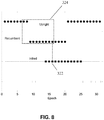
- Fig. 8 shows the "in-bed” classification outcome for a sequence of upright/recumbent body orientations.
- a preferred embodiment of the present invention makes its epoch-by-epoch "in-bed” classification based on the 10 most recent epochs.
- the "in-bed” status is considered to be "true”, as indicated by a solid square 322, because 8 out of the most 10 recent body orientations (the 10 most recent body orientations for the 16 th epoch are shown within the dotted box 324) are recumbent (with only 2 of the 10 most recent body orientations being classified as upright).
- the previous "in-bed" classification is retained for the current epoch.
- the data shown in Fig. 8 provides a basis for determining when the user is in-bed.
- Fig. 9 illustrates the calculation results for the activity level count M T .
- the instantaneous acceleration trace 304 from Fig. 6 is reproduced in Fig. 9 .
- the activity level count M T for an epoch is the average of the instantaneous acceleration data within that epoch.
- the instantaneous acceleration data reveals that activity is progressively higher from the first epoch 335 to the second epoch 336 and to the third epoch 337.
- the activity level count at the third epoch 337 is higher than that of the second epoch 336 which in turn is higher than that of the first epoch 335.
- the BMM for a particular time is defined as the median of the activity level counts for the most recent twenty epochs.
- the BMM is compared against a threshold value ( ⁇ ) of 0.1g. If the BMM is below the threshold value, the user's body is classified as having a "low activity" status.
- ⁇ a threshold value of 0.1g. If the BMM is below the threshold value, the user's body is classified as having a "low activity" status.
- the data shown in Fig. 9 provides a basis for determining the user's activity level (i.e., for determining when the user should be classified as having a "low activity” status).
- the preferred embodiment of the present invention uses both "in-bed” status and "low activity” status, either individually or jointly, to adjust operation of the novel TENS device. More particularly, the preferred embodiment of the present invention is configured to reduce the stimulation intensity level of TENS device 100 when the user is characterized as having "in-bed” status, or "low activity” status, or both.
- Fig. 10 provides an example of how the novel TENS device of the present invention adjusts its stimulator operation according to the user's body and measurement status derived from the accelerometer data.
- Fig. 10 shows, from top to bottom, user behavior 350, user "in-bed” status 360, user "low activity” status 370, and operation of the TENS stimulator 380.
- the novel TENS device is positioned on the upper calf of the user so as to trigger the on-skin condition and thereby start activity monitoring.
- stimulator 105 delivers normal stimulation with intensity 381 during an evening activity period 351.
- the "in-bed” status of the user is “off' and the “low activity” status of the user is “off (following an initial "on” period 371).
- the data from accelerometer 152 indicates the user has become recumbent and that this body orientation has been maintained for a certain number of epochs, so the "in-bed” status is changed to the "on" state 361 (after some delay because the "in-bed” detector in the preferred embodiment requires analysis of a certain number of recumbent body position epochs in order to make the "in-bed” determination).
- the user may still move his/her leg for some period of time while the user is in-bed, but the user typically thereafter enters a quiet period with low BMM, so the "low activity" status is changed to the "on” state 372 after an additional delay.
- the novel TENS device 100 reduces the intensity of its stimulator output to a lower level 382 once the "in-bed” status is turned on, in order to help the user to fall into sleep by moderating the stimulation intensity level below the "strong but comfortable” level 381 (which is more suitable for daytime TENS therapy) to the lower level 382 (which is more suitable for falling into sleep).
- the user is disturbed by the stimulation sensation (even at the reduced stimulation intensity level 382 discussed above) and moves his/her legs at time instance 353.
- This leg activity causes a change from the "low activity" status 373.
- the TENS stimulator 105 compensates for this by further reducing its stimulation intensity level to a new, lower stimulation intensity level 383.
- pain sensation causes the user to move his/her leg (while maintaining a recumbent orientation by staying in bed), so that the "low activity" status is changed to "off at 374.
- the novel TENS device recognizes the combination of stimulation “off, “low activity” status "off, and “in-bed” status "on”, which reflects the user experiencing pain while lying in bed. Instead of waiting until time instance 385 (when the timer would automatically start the next TENS therapy session), the TENS device automatically starts the next TENS therapy session early, (at time instance 384).
- the present invention uses an accelerometer incorporated in the TENS device to measure acceleration of the TENS device (and hence to measure acceleration of the body limb to which the TENS device, and hence the accelerometer, are attached) in the x-axis, y-axis and z-axis directions.
- the y-axis data is compared to the earth gravity vector g in the manner discussed above to determine the orientation of the user, and this orientation may be characterized as "recumbent" status or "upright” status.
- the x-axis data, the y-axis data and the z-axis data is used in the manner discussed above to determine body movement, and this body movement may be characterized as "low activity” status or "non-low activity” status.
- the recumbent/upright status and the low activity/non-low activity status is used in the manner discussed above to determine if the user is likely to be in bed, and this determination may be characterized as "in-bed” status or "non in-bed” status.
- the TENS device is configured so that if the user has "in-bed” status, the TENS device reduces the stimulation intensity level from a higher "wake” state level to a lower "sleep” state level. User orientation and body movement are thereafter monitored. If the user remains recumbent and body movement thereafter increases (e.g., potentially signifying that pain is awakening the user from sleep), the TENS device is configured to increase the stimulation intensity level so as to provide increased pain relief and thereby help the user remain asleep.
- the TENS device is configured to increase the stimulation intensity level to a higher level (e.g., to a normal "wake" state level) so as to provide increased pain relief to the user.
- the activity and orientation status of the user can also be utilized during daytime use to modify the operation of the TENS stimulator.
- the activity and orientation status of the user can be used to modify the operation of the TENS stimulator during a daytime sleep session, e.g., to reduce the stimulation intensity level during a daytime nap.
- the activity and orientation status of the user can also be used irrespective of the sleep-wake state of the user.
- the activity and orientation status of the user can be used to modify the operation of the TENS stimulator during a daytime work session (e.g., to reduce the stimulation intensity level when a user is seated at their desk), or to modify the operation of the TENS stimulator during normal daily activities (e.g., to increase the stimulation intensity level when the user is walking or running, etc.), etc.
- the present invention provides a transcutaneous electrical nerve stimulator with the automatic detection of user activities, wherein the TENS stimulator may be pre-programmed to modify its operation according to the detected user activity.
Landscapes
- Health & Medical Sciences (AREA)
- Life Sciences & Earth Sciences (AREA)
- Engineering & Computer Science (AREA)
- Public Health (AREA)
- Veterinary Medicine (AREA)
- Biomedical Technology (AREA)
- Heart & Thoracic Surgery (AREA)
- Animal Behavior & Ethology (AREA)
- General Health & Medical Sciences (AREA)
- Biophysics (AREA)
- Physics & Mathematics (AREA)
- Pathology (AREA)
- Medical Informatics (AREA)
- Molecular Biology (AREA)
- Surgery (AREA)
- Theoretical Computer Science (AREA)
- Computer Hardware Design (AREA)
- Radiology & Medical Imaging (AREA)
- Nuclear Medicine, Radiotherapy & Molecular Imaging (AREA)
- General Engineering & Computer Science (AREA)
- Pain & Pain Management (AREA)
- General Physics & Mathematics (AREA)
- Human Computer Interaction (AREA)
- Oral & Maxillofacial Surgery (AREA)
- Dentistry (AREA)
- Anesthesiology (AREA)
- Physiology (AREA)
- Hospice & Palliative Care (AREA)
- Psychiatry (AREA)
- Measurement Of The Respiration, Hearing Ability, Form, And Blood Characteristics Of Living Organisms (AREA)
- Electrotherapy Devices (AREA)
- Neurology (AREA)
Description
- This invention relates generally to Transcutaneous Electrical Nerve Stimulation (TENS) devices that deliver electrical currents across the intact skin of a user via electrodes so as to provide symptomatic relief of pain, and more particularly to detecting the sleep-wake state of the user in order to enhance the device's pain-relieving benefits at nighttime.
- Transcutaneous Electrical Nerve Stimulation (TENS) devices apply electrical currents to particular areas of the human body in order to suppress pain. The most common form of TENS is called conventional TENS. In a conventional TENS device, an electrical circuit generates stimulation current pulses with specified characteristics. The pulse waveform specifications include intensity (mA), duration (µsec) and shape (typically monophasic or biphasic). The pulse pattern specifications include the frequency (Hz) of the stimulation pulses and the length of each continuous stimulation session (minutes).
- Electrical stimulation is typically delivered to the user through electrodes, with the electrical stimulation being in the form of low intensity (typically less than 100 mA), short duration (typically 50-400 µsec) pulses at frequencies typically between about 10 and 200 Hz. The electrodes are placed on the skin of the user within, adjacent to, or proximal to, the area of pain. The electrodes typically utilize hydrogels to create a stable low-impedance electrode-skin interface to facilitate the delivery of electrical current to the user so as to stimulate peripheral sensory nerves, whereby to suppress pain.
- Poor sleep quality is one of the major causes of morbidity in patients suffering from chronic pain [Fishbain DA, Hall J, Meyers AL, Gonzales J, Mallinckrodt C. Does pain mediate the pain interference with sleep problem in chronic pain? Findings from studies for management of diabetic peripheral neuropathic pain with duloxetine. J Pain Symptom Manage. Dec 2008;36(6):639-647]. It is, therefore, desirable that patients have the option of receiving TENS therapy during sleep. In fact, several studies have shown that TENS therapy can improve sleep quality (see, for example, Barbarisi M, Pace MC, Passavanti MB, et al. Pregabalin and transcutaneous electrical nerve stimulation for postherpetic neuralgia treatment. Clin J Pain. Sep 2010;26(7):567-572).
- A significant safety concern for traditional TENS use is the potential for "electrode peeling" (i.e., where the electrodes of the TENS device unintentionally separate from the skin of the user). Such electrode peeling can result in current density and power density increases due to decreased electrode-skin contact area. Increased current density and power density could lead to painful stimulation and, in the extreme, thermal burns. The U.S. Food and Drug Administration (FDA) has published draft guidelines on TENS devices that require a warning against the use of conventional TENS devices during sleep due to the risk of unintended electrode peeling [Food and Drug Administration, Draft Guidance for Industry and Staff: Class II Special Controls Guidance Document: Transcutaneous Electrical Nerve Stimulator for Pain Relief, April 5, 2010]. Consequently, most TENS devices are designed to operate exclusively during the day (i.e., during wake state) without any nighttime (i.e., sleep state) operation.
- In pending prior
U.S. Patent Application Serial No. 14/230,648 - To achieve maximum pain relief, electrical stimulation needs to be at an adequate intensity level [Moran F, Leonard T, Hawthorne S, et al. Hypoalgesia in response to transcutaneous electrical nerve stimulation (TENS) depends on stimulation intensity. J Pain. 12:929-935)]. The optimal TENS therapeutic intensity level is often described as the intensity level that evokes "strong but comfortable" sensation from a user. However, a stimulation intensity level tailored for daytime (i.e., wake state) use may be too strong for nighttime (i.e., sleep state) use since the stimulation intensity level appropriate for the wake state may interfere with sleep.
- Another common feature of a TENS device is its "on-demand" pain relief operation. A pain-relieving TENS therapy session typically starts immediately when the user interacts with the device in a prescribed manner, such as by pressing a button on the TENS device. Each therapy session typically lasts for about 60 minutes. While on-demand therapy gives the user complete control over the timing of each TENS therapy session, on-demand therapy is not well suited for nighttime (i.e., sleep state) use as it requires deliberate and regular interaction with the TENS device by the user.
- For these reasons, it would be advantageous to provide automated means to detect the user's sleep-wake state so that the TENS device can automatically alter its operation according to the daytime (i.e., wake state) or nighttime (i.e., sleep state) needs of the user. In addition to delivering effective pain therapy during the daytime, it would be advantageous if the TENS device could adjust its therapeutic stimulation parameters (such as the stimulation intensity level) during nighttime (i.e., sleep state) so as to avoid interference with sleep. Thus, in order to strengthen its utility at nighttime (i.e., during sleep state) for pain relief without interrupting sleep, the TENS device should monitor the sleep state and sleep quality of the user and adapt its operation (e.g., adjust its stimulation intensity level) accordingly.
- The gold standard in determining the sleep-wake state of a subject is polysomnography which comprises at least three distinct types of data (i.e., EEG, EOG and EMG). Because of difficulty in recording and analyzing these types of data, actigraphy has been developed and refined over the last 30 years as a practical alternative to study sleep/awake patterns [Ancoli-Israel S, Cole R, Alessi C, Chambers M, Moorcroft W, Pollak CP. The role of actigraphy in the study of sleep and circadian rhythms. Sleep. May 1 2003;26(3):342-392]. Actigraphy is a continuous recording of body movement by means of a body-worn device that detects body movement, typically through the use of accelerometers. Significantly, the present invention integrates an actigraphy-based sleep-wake classification method with conventional TENS device functionality in order to provide a novel method and apparatus for enhancing the pain-relieving utility of TENS therapy at nighttime (i.e., during sleep state) without disturbing the sleep of the TENS user.
-
US-A-2013/0158627 discloses a TENS device comprising a housing, stimulation means for electrically stimulating at least one nerve, an electrode releasably mounted to the housing and connectable to the stimulation means for electrical stimulation of the at least one nerve, monitoring means for monitoring the user's body orientation and movement, and analysis means for analyzing said orientation and movement. -
WO-A-03/051453 - The present invention comprises the provision and use of a novel TENS device which comprises a TENS stimulator designed to be placed on the patient's upper calf (or other anatomical location) and a pre-configured electrode array designed to provide circumferential stimulation in the area of the upper calf (or other anatomical location). An accelerometer incorporated in the TENS device continuously monitors body orientation and movement of the user in order to determine the user's sleep-wake state. A key feature of the present invention is that the TENS device is adapted to adjust its stimulation parameters based on the user's sleep-wake state, which is determined by the aforementioned analysis of body orientation and movement. The user is considered to be "in-bed" if the user's body orientation is determined to be recumbent for a selected portion (e.g., a majority) of a selected time period (e.g., a decision window). A measure of user body movement, based on the concept of actigraphy, is used to quantify the user's activity level. The user is considered to be asleep if the user is "in-bed" and if the activity level (i.e., body movement) of the user remains low for a selected period of time. "In-bed" status, low activity level, and sleep state can be used individually or collectively by the TENS device to adjust stimulator output, such as stimulation pulse waveform parameters.
- The present invention provides an apparatus according to
claim 1. Preferred embodiments are defined in the dependent claims. Aspects, embodiments and examples not falling under the scope ofclaim 1 do not form part of the invention. The latter applies in particular to the methods described herein. - These and other objects and features of the present invention will be more fully disclosed or rendered obvious by the following detailed description of the preferred embodiments of the invention, which is to be considered together with the accompanying drawings wherein like numbers refer to like parts, and further wherein:
-
Fig. 1 is a schematic view showing a novel TENS device formed in accordance with the present invention, with the novel TENS device being mounted to the upper calf of a user; -
Fig. 2 is a schematic view showing the novel TENS device ofFig. 1 in greater detail; -
Fig. 2A is a schematic view of the novel TENS device shown inFigs. 1 and2 ; -
Fig. 2B is a schematic view of the novel TENS device ofFigs. 1 and2 , including its user activity detector; -
Fig. 3 is a schematic view showing the on-skin detection system of the novel TENS device shown inFigs. 1 and2 , as well as its equivalent circuits when the novel TENS device is on and off the skin of a user; -
Fig. 4 is a schematic view showing the orientation of the accelerometer incorporated in the novel TENS device ofFigs. 1 and2 , when the novel TENS device ofFig. 1 is mounted to the upper calf of a user; -
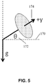
Fig. 5 is a schematic view showing the relationship between gravitational acceleration and the y-axis acceleration vector of the accelerometer in the novel TENS device when the novel TENS device (disposed on the user's leg) rests at an angle with respect to the horizontal plane; -
Fig. 6 is a schematic view showing the accelerometer measurements in all three axes and the calculated instantaneous acceleration values for a three-minute period with various body position and movement patterns of a user wearing the novel TENS device; -
Fig. 7 is a schematic view showing the raw y-axis accelerometer measurement data, intermediate results of body orientation analysis, and the body orientation results for the same three minute period ofFig. 6 ; -
Fig. 8 is a schematic view showing body orientation results and the "in-bed" classification results based on the body orientation results of 30 epochs; -
Fig. 9 is a schematic view showing the instantaneous acceleration calculated from the data shown inFig. 6 and the corresponding activity level counts for the three-minute period ofFig. 6 ; and -
Fig. 10 is a schematic view showing the timing diagram of the interactions between the user body orientation and movement status and operation of the stimulator of the novel TENS device. -
Fig. 1 illustrates anovel TENS device 100 formed in accordance with the present invention, with the novel TENS device being shown worn on a user'supper calf 140. A user may wear oneTENS device 100 on either leg, or wear two TENS devices, one on each leg. -
TENS device 100 is shown in greater detail inFig. 2 and preferably comprises three components: astimulator 105, astrap 110, and an electrode array 120 (comprising a cathode electrode and an anode electrode appropriately connected to stimulator 105 as is well known in the art).Stimulator 105 preferably comprises three mechanically and electricallyinter-connected compartments Compartments Fig. 2 ), thereby allowingTENS device 100 to conform to the curved anatomy of a user's leg. In a preferred embodiment,compartment 102 houses the TENS stimulation hardware (except for a battery) anduser interface elements Compartment 102 also houses an accelerometer 152 (seeFigs. 2B and4 ), preferably in the form of a semiconductor chip accelerometer, for detecting user gestures, user body position and orientation, and user movement and activity levels (see below).Compartment 102 also houses a real-time clock 505 (Fig. 2B ). In a preferred embodiment, compartments 101 and 103 are smaller, auxiliary compartments that house a battery for powering the TENS stimulation hardware and other ancillary elements, such as an ambient light sensor or detector 510 (Figs. 2B and4 ) for determining ambient light conditions and a wireless interface unit (not shown) for allowingTENS device 100 to wirelessly communicate with other elements (e.g., another TENS device being worn on the other leg of the user). In another embodiment of the present invention, only onecompartment 102 may be provided for housing all of the TENS stimulation hardware, battery, and other ancillary elements of the present invention without the need forside compartments - Still looking now at
Fig. 2 ,interface element 106 comprises a push button for user control of electrical stimulation, andinterface element 108 comprises an LED for indicating stimulation status and providing other feedback to the user. Additional user interface elements (e.g., an LCD display, audio feedback through a beeper or voice output, haptic devices such as a vibrating motor, electrical feedback by pulsing the stimulus, etc.) may also be provided and are considered to be within the scope of the present invention. - The preferred embodiment of the present invention is designed to be worn on the
upper calf 140 of the user as shown inFig. 1 .TENS device 100, comprisingstimulator 105,electrode array 120, andstrap 110, is secured toupper calf 140 by placing the apparatus in position and then tighteningstrap 110. Although the preferred embodiment of the present invention comprises placement of the TENS device on the upper calf of the user, additional anatomical locations (such as above the knee, on the lower back, and on an upper extremity) are contemplated and are also considered to be within the scope of the present invention. -
Fig. 2A is a schematic representation of the current flow between a TENS device and the user. As seen inFig. 2A , stimulation current 415 from a controlledcurrent source 410 flows into the user'stissue 430 viacathode electrode 420.Cathode electrode 420 consists of conductive backing (e.g., silver hatch) 442 andhydrogel 444. The current passes through the user'stissue 430 and returns tocurrent source 410 through anode electrode 432 (anode electrode 432 also comprises aconductive backing 442 and hydrogel 444). It should be appreciated that the designation of anode and cathode electrodes is purely notational in the context of a biphasic waveform (i.e., when the biphasic stimulation pulse reverses its polarity in its second phase of the biphasic TENS stimulation, current will be flowing into the user's body viainterface 432 and out of the user's body viainterface 420.) - Further details regarding the construction and use of the foregoing aspects of
TENS device 100 are disclosed in (i) pending priorU.S. Patent Application Serial No. 13/678,221, filed 11/15/2012 by Shai N. Gozani et al. U.S. Patent Application Serial No. 14/230,648, filed 03/31/2014 by Shai N. Gozani et al. - When the TENS device is secured in position on the user's upper calf, the position and orientation of
accelerometer 152 inTENS device 100 is fixed and known relative to the lower limb of the user. Tight mechanical coupling betweenTENS device 100 andlower limb 140 allows lower limb movement be accurately measured byaccelerometer 152. Such tight mechanical coupling is established throughstrap 110. If desired, a tension gauge 109 (Fig. 1 ) may be provided onstrap 110 to confirm that a tight mechanical coupling is established betweenTENS device 100 andlower limb 140. Data fromaccelerometer 152 are analyzed in real time to determine the orientation and movement oflower limb 140 of the user. The orientation, movement, and activity level of lower limb 140 (determined by analyzing the data from accelerometer 152) are used to determine the sleep-wake state of the user. Based on the sleep-wake state of the user, the TENS device can modify its stimulation pattern (such as the stimulation intensity level and the onset of the stimulation). A strong but comfortable stimulation intensity level may be ideal for a user during the daytime (i.e., during wake state); but the same stimulation intensity level during nighttime may evoke a sensation that prevents the user from falling asleep or may cause the user to wake up from sleep. Therefore, the TENS device is preferably configured to lower its therapeutic stimulation intensity level when the user is determined to be asleep. - The orientation and movement components measured by the present invention may contribute individually or collectively to the determination of the sleep-wake state of the user. In one preferred form of the invention, the TENS device measures calf orientation, which is highly correlated with body orientation. More particularly, upright body orientation is generally a reliable indicator that the user is in a wake state, while recumbent orientation suggests a resting state (e.g., such as occurs during sleep). Regular and robust body movement is more likely the result of user activities during the daytime (i.e., during wake state), while quiet or low-level spontaneous movements are more likely during nighttime (i.e., during sleep state). Interactions of body orientation and movement level can also be useful in identifying the sleep-wake state of the user (i.e., thereby enhancing a sleep-wake state classification). Specifically, recumbent body orientation and a low-level of physical activity is generally a good indicator that the user is asleep. In addition, real-
time clock 505 allows assigning a nontrivial a priori probability of the sleep-wake state at any given time of the day in order to further refine the sleep-wake state classification results obtained by the aforementioned analysis of orientation and movement data (i.e., a user is more likely to be asleep at 3:00 am and less likely to be asleep at 4:00 pm). In a preferred embodiment of the present invention, to reflect that the a priori sleep state probability is low at a specific daytime window, the conditions for classifying user body orientation as recumbent or for classifying user sleep-wake state as asleep, can be made more stringent. - In another embodiment, output from ambient
light sensor 505 is used to assign a nontrivial a priori probability of the sleep-wake state in order to improve sleep-wake classification results. In other words, ambientlight sensor 505 can be used to determine if the user is in a setting which has an illuminated or non-illuminated ambience: a user is more likely to be sleeping in a dark setting than in a brightly lit setting. -
Fig. 2B shows aTENS device 100 which comprises a "user activity"detector 500 , whereinuser activity detector 500 comprises theaforementioned accelerometer 152, real-time clock 505, ambientlight detector 510, means 515 for calculating user activity (e.g., a microprocessor of the sort well known in the art, with appropriate programming to provide the functionality disclosed herein to allow a determination of user activity), and means 520 for modifying the stimulation intensity level (e.g., the magnitude of the current) according to the determination made of user activity (e.g., a controller for controlling the controlledcurrent source 410, wherein the controller is of the sort well known in the art, controlled by the aforementioned microprocessor so as to provide the functionality disclosed herein). - It will be appreciated that the orientation and activity measures from
accelerometer 152 inTENS device 100 only become coupled with the orientation and activity of a user when the TENS device is worn by the user. In a preferred embodiment, an on-skin detector is provided to determine whether and whenTENS device 100 is securely placed on the user's upper calf. Only whenTENS device 100 is determined to be on-skin, does the orientation and activity data fromaccelerometer 152 of the TENS device become relevant in estimating the orientation and movement of the user. - To this end, in a preferred embodiment of the present invention, and looking now at
Fig. 3 , the on-skin detector may be provided withinTENS device 100. More particularly, in one preferred form of the invention, a voltage of 20 volts fromvoltage source 204 is applied to theanode terminal 212 of TENS stimulator 105 by closing theswitch 220. If the TENS device is worn by the user, thenuser skin 430, interposed betweenanode electrode 420 andcathode electrode 432, will form anequivalent resistor 208 in a voltage divider circuit. More particularly, whenTENS device 100 is on the skin of the user, theequivalent circuit 260 shown inFig. 3 represents the real-world system andequivalent circuit 260 allows theanode voltage V a 204 to be sensed through thevoltage divider resistors amplifier 207 will be non-zero and close to theanode voltage 204. On the other hand, whenTENS device 100 is not on the skin of the user, theequivalent circuit 270 represents the real-world system and the cathode voltage fromamplifier 207 will be zero. - User orientation, either upright or recumbent, may be approximated by static orientation measured by
accelerometer 152 whenTENS device 100 is placed on the user's upper calf 140 (Fig. 1 ). Strictly speaking, the accelerometer orientation matches that of the lower leg. In a preferred embodiment, and looking now atFig. 4 ,accelerometer chip 152 is placed on thecircuit board 151 housed insidecompartment 102, so that the accelerometer's 3-axis directions 153 (i.e., x-axis, y-axis, z-axis) are known and fixed whenTENS device 100 is placed on the user's upper calf. - A stationary upright user, or one sitting with feet resting on the ground, will have an upright calf orientation. Consequently, the y-axis acceleration of
accelerometer chip 152 will have a value of about -1g due toearth gravity 154, where g is the standard acceleration due to earth gravity. The above measurement holds true regardless of the exactrotational position 160 ofcompartment 102 aroundupper calf 140. WhenTENS device 100 is placed upside down on the upper calf, an allowable placement position, the accelerometer axis directions rotate as shown in 155. In this case, a stationary upright user will have a measured acceleration value along the y-axis of about +1g. By contrast, a stationary recumbent user lying with legs flat on a bed will have a measured acceleration value along the y-axis of about 0g. In a preferred embodiment, if the absolute value of the y-axis acceleration is greater than a threshold level, then the orientation of the user is considered to be upright, otherwise the orientation of the user is considered to be recumbent. In a preferred embodiment, this threshold level for determining upright/recumbent is 0.50g, corresponding to a leg angle of about 30° from the horizontal plane. However, other threshold values may also be used. - It is unrealistic to expect a user wearing
TENS device 100 to remain stationary or motionless, particularly during the daytime (i.e., during wake state). Therefore, it is advantageous to provide a method for determining body orientation that takes into account additional acceleration projected to the y-axis ofaccelerometer 152 due to user body movement. More particularly, and looking now atFig. 5 , where the earth's gravitational vector direction is fixed as downward,angle θ 172 represents the angle between the positive accelerometer y-axis direction 174 and the truehorizontal plane 170. Then the accelerometer measurement along the y-axis becomes
upper calf 140 and is fixed for each placement. Body movement component m(t) is considered as "noise" in the context of determining body orientation. - In a preferred embodiment, an orientation detection algorithm, taking into account user body movement, is implemented as follows.
-
Step 1. Set a target threshold θ0 for the angle θ so that |θ| < θ0 corresponds to the case where the upper calf of the user is recumbent. In a preferred embodiment, the target angle threshold θ0 is set to 30°. -
Step 2. Average Ay(t) over a time window of length N (t=T-N+1, T-N+2, ..., T) to reduce the effect of non-stationary noise m(t) (i.e., to reduce the effect of the body movement component m(t)). The result of this averaging is denoted as Ay,T. Estimated standard deviation σy,T is calculated, and standard error of the mean is calculated: SET =σy,T /sqrt(N). In a preferred embodiment, the accelerometer measurements are sampled at 50Hz and the average window length is N=3000, corresponding to a one-minute time window. Each non-overlapping window forms an "epoch". The angle θT is then estimated, using the formula:
-
Step 3. Calculate a context-dependent threshold θC,T that takes into account an estimation error of the angle θ and implements a hysteresis effect so as to prevent rapid switching of the body orientation state. The target threshold θ0 is adjusted by the amount [θH + α*SET ] to arrive at θC,T , where α relates to the confidence level of the estimated mean Ay,T. In a preferred embodiment, the hysteresis parameter θH is set to 2.5° and α is set to 3.0. The adjustment is by way of addition if the absolute value of the previous angle is below threshold θC,T-1, such that: θC,T = θ0 + [θH + α*SET]; otherwise, the adjustment is by way of subtraction, such that: θC,T = θ0 - [θH + α*SET]. - Step 4. Compare the estimated angle θT (determined in Step 2) and the context-dependent threshold θC,T (determined in Step 3). If the absolute value of θT is greater than the context-dependent threshold θC,T , then the body orientation is considered to be (i.e., the body orientation is classified as) upright for the current epoch. Otherwise, the body orientation is classified as recumbent.
-
Step 5. Examine the body orientation states of multiple consecutive epochs. While the body orientation of an individual epoch is accurate, the body orientation of the user over a longer time period is more informative and relevant in determining the sleep-wake state of the user. In a preferred embodiment, the majority of the body orientation over the last ten epochs is used to identify the true state of the user body orientation for the purposes of sleep-wake classification. An update to the body orientation state can be as fast as each new epoch becoming available or as slow as waiting for an entirely new set of epochs to arrive. The preferred embodiment updates body orientation state with the arrival of each new epoch. In other words, where each epoch is one minute in length, the user body orientation determination may be updated as fast as once a minute. - Thus it will be seen that
user activity detector 500 ofTENS device 100 uses the output ofaccelerometer 152 to determine the body orientation of the user. More particularly,user activity detector 500 analyzes the y-axis data received fromaccelerometer 152 to determine the orientation of the body of the user. In one preferred form of the invention, this is done by removing the body movement component from the y-axis data reported byaccelerometer 152, and then comparing the y-axis data with the earth gravity vector g so as to determine the orientation of the body of the user. - Human body movement is often measured quantitatively by actigraphy. Actigraphy is a continuous recording of body movement by means of a body-worn device that detects movement, typically through acceleration. Although commonly measured with a wrist-worn device, movement can be recorded at various body locations, including the lower leg. Actigraphy is effective in estimating and differentiating sleep-wake states because there is less movement during the sleep state and more movement during the wake state [Ancoli-Israel S, Cole R, Alessi C, Chambers M, Moorcroft W, Pollak CP. The role of actigraphy in the study of sleep and circadian rhythms. Sleep. May 1 2003;26(3):342-392.].
- When
TENS device 100 is worn on the user'supper calf 140, lower leg movement will be captured byaccelerometer 152 of the TENS device. Each axis ofaccelerometer 152 measures the projection of the acceleration vector along that axis. Like many time-varying signals, the accelerometer measurement for each axis consists of a low frequency (slow varying) component and a high frequency (fast varying) component. The low frequency component is useful in assessing the body orientation of the user by estimating the gravitational force projection onto each axis of the accelerometer. A preferred embodiment, focusing on the y-axis measurement of the accelerometer, was described earlier for determining body orientation. The high frequency component captures acceleration as a result of user body movement events such as walking, running, climbing stairs, etc. - Although acceleration in each individual axis of the accelerometer contains unique and useful information for user body movement analysis, the instantaneous acceleration, A(t), defined in
Equation 1 below, is commonly used to characterize the level of activity level, a relevant measure for sleep-wake classification.
- In a preferred embodiment, the single-axis acceleration components Ax(t), Ay(t), and Az(t) of
accelerometer 152 are sampled at 50Hz (although other sampling rates may also be used). Sampled acceleration components are band-pass filtered between 0.25Hz and 12.0Hz. The high-pass aspect of this band-pass filter reduces the effect of acceleration components which are not directly linked to body movement. For example, the gravitational force projection on each axis is substantially constant and its frequency is generally below 0.25Hz, so this high-pass filter will remove that acceleration component as it is considered irrelevant to body movement activity levels. Body mass and physical limitation also constrains the frequency of accelerations caused by voluntary body movement. Filtering out frequency components higher than 12.0Hz greatly reduces the effect of external environment factors such as high-frequency vibrations sensed byaccelerometer 152 when the user is in a moving vehicle. - Filtered single-axis acceleration components Ax(t), Ay(t), and Az(t) are then combined via
Equation 1 to form the actigraphy signal A(t). In a preferred embodiment, values of A(t) are averaged over one-minute epochs to yield minute-by-minute activity level counts. The T-th minute activity level count is given by Equation 2:

- The movement measure threshold χ may be derived from published literature or determined experimentally [Cole RJ, Kripke DF, Gruen W, Mullaney DJ, Gillin JC. Automatic sleep/wake identification from wrist activity. Sleep. Oct 1992;15(5):461-469.] using polysomnography as a gold standard [Sadeh A. The role and validity of actigraphy in sleep medicine: an update. Sleep Med Rev. Aug 2011;15(4):259-267.] [Tryon WW. Issues of validity in actigraphic sleep assessment. Sleep. .]. The performance of the actigraphy signal-based BMM for sleep-wake classification is expected to have high sensitivity but low specificity for sleep [Paquet J, Kawinska A, Carrier J. Wake detection capacity of actigraphy during sleep. Sleep. Oct 2007;30(10):1362-1369.]. In other words, if the user is actually sleeping, then the BMM is very likely to be low. However, if the user is in a waking but restful state then the BMM may be low as well. In a preferred embodiment, specificity is improved by using a comparatively long 20 minute monitoring window with an additional requirement of recumbent body position, which has been shown to increase specificity [Cole RJ, Kripke DF, Gruen W, Mullaney DJ, Gillin JC. Automatic sleep/wake identification from wrist activity. Sleep. Oct 1992;15(5):461-469].
- The threshold χ for BMM, however it may be initially determined, can benefit from a real-time optimization process to tailor (i.e., improve) its performance (i.e., accuracy) for individual users. For the same body movement, acceleration signals acquired by
accelerometer 152 incorporated inTENS device 100 may be different in size and morphology as a result of placement variations. In addition, different users will have different body movement patterns prior to and during sleep. In one embodiment, the threshold parameter χ is initially set to a high value so that it is more sensitive for sleep classification based on BMM values. If the TENS device determines that the user is consistently awake post sleep classification, the threshold parameter χ is adjusted to a lower (i.e., more stringent) value to increase specificity. The device determination that a user is in a wake state can be based on deliberate interactions between the user and the device, an increase in BMM values in subsequent epochs, and a body orientation change to upright. Misclassification can also be determined by a significant time lag between the sleep classification event timestamp from real-time clock 505 and self-reported sleep time by the user. However, threshold parameter adjustments are preferably not based on a single misclassification but rather on a sequence of misclassifications. - The threshold χ for BMM can also be made to be a function of the user body orientation state or orientation angle. For example, when the orientation angle θ is just below the recumbent orientation threshold, the threshold χ can be made smaller to strengthen the quality of the low body movement classification. This is especially useful when the body orientation and body movement classification results are used together to determine the sleep-wake state of the user.
- Thus it will be seen that
user activity detector 500 ofTENS device 100 uses the output ofaccelerometer 152 to determine the body movement and activity levels of the user. More particularly,user activity detector 500 analyzes the x, y and z-axis data received fromaccelerometer 152 to determine the extent of body movement of the user. In one preferred form of the invention, this is done by looking at the instantaneous acceleration of the body of the user over a period of time and comparing it against a pre-determined threshold. - The present invention aims to maximize the pain-relieving therapeutic value of
TENS device 100 while minimizing any potential interference ofTENS device 100 with the sleep quality of the user when TENS therapy is delivered to the user during nighttime (i.e., sleep state). To minimize interference to sleep, operation of the TENS device should be modified before and during an actual user sleep phase, e.g., by reducing the TENS stimulation intensity level. For example, when the user is in bed and getting ready to sleep, a strong stimulation sensation may prevent the user from falling into sleep. Similarly, starting a therapy session while the user is asleep with a TENS stimulation intensity level that is appropriate for daytime use may wake the user from sleep. For the TENS device to overcome the potential disadvantages of nighttime application while remaining effective during daytime, the TENS device should modify its manner of operation in accordance with the in-bed status and the sleep-wake state of the user (i.e., the higher stimulation intensity level associated with the wake state should be reduced to a lower stimulation intensity level appropriate for the sleep state). - Body orientation and body movement can be used individually to determine whether a user is in bed or not. Combining body orientation and body movement orientation can improve the accuracy of the in-bed detection determination.
- In one preferred embodiment, only body orientation is considered for the in-bed determination. When five or more epochs of the 10 most recent epochs of an observation period indicate a recumbent orientation, the user is considered to be in "in-bed" status. As a result, stimulation intensity is reduced by 2dB (equivalent to reducing the stimulation current intensity by 20%). This lowered stimulation intensity reduces the stimulation sensation felt by the user so that the user can fall into sleep easier.
- In another preferred embodiment, both orientation and BMM factors are considered. The threshold for BMM is set higher than the threshold value intended to classify the user's sleep-wake status, inasmuch as the criteria is to determine whether the user is in a "pre-sleep" in-bed state, that is, in a recumbent position with low body movement activity. In other words, a given BMM may satisfy the threshold for in-bed classification but may not satisfy the threshold for sleep classification.
- It is known that an actigraphy-based sleep study often classifies a person's sleep state ahead of the reference standard based on polysomnography [Paquet J, Kawinska A, Carrier J. Wake detection capacity of actigraphy during sleep. Sleep. Oct 2007;30(10): 1362-1369.]. The reason is that the recumbent position, coupled with low body movement, often precedes (but does not necessarily coincide with) the actual sleep stage. The body position and movement activity level during this "pre-sleep" in-bed period is indistinguishable from that of the actual sleep period. While this may pose a challenge for using actigraphy to classify sleep state in a traditional sleep study context, the time gap between the in-bed state and actual sleep state is advantageous for the TENS therapy application. In order to help the user to fall into sleep quickly when a TENS therapy session is ongoing, it is desirable to reduce the stimulation intensity during the "pre-sleep" phase. Otherwise, the actual sleep phase can be delayed until the current TENS therapy session is completed due to the strong sensation of the normal daytime TENS stimulation intensity.
- In a preferred embodiment, the TENS therapy session will automatically restart every two hours, with each session lasting for one hour, when the TENS device determines that the in-bed status is valid. This auto-restart feature allows TENS therapy be delivered to the user throughout the night (i.e., during sleep state) so as to provide pain relief at regular intervals, such that the likelihood of the user being awoken by pain is minimized.
- Thus it will be seen that
user activity detector 500 ofTENS device 100 uses the output ofaccelerometer 152 to determine the "in-bed" status of the user. More particularly,user activity detector 500 analyzes the aforementioned body orientation determination, and the aforementioned body movement and activity level determination, to determine the in-bed status of the user in order for the TENS device to modify its operation, such as reducing stimulation intensity level when the "in-bed" status is detected. - In a preferred embodiment of the present invention, body orientation and body movement are monitored during nighttime via the on-
board accelerometer 152. The actigraphy-based feature BMM is used to assess sleep quality and body orientation is used so as to filter out any period during which the user may be out of bed. Activity levels during the actual TENS stimulation period are used to refine the nighttime stimulation intensity level. If the nighttime stimulation intensity level is too strong, it may cause an unconscious but deliberate reaction such as increased body movement from the user. Therefore, it is desirable for the nighttime stimulation intensity level to be adjusted where necessary in order to keep nighttime stimulation from disturbing the user (which disturbance is reflected by increased BMM). - In one preferred embodiment of the present invention, when an increase in BMM is detected during nighttime TENS stimulation, the TENS device decreases the stimulation intensity level for a pre-determined period of time (e.g., five minutes). If this decrease in the stimulation intensity level is successful in decreasing BMM (i.e., the stimulation intensity has been lowered to a level which is no longer disturbing the user),
TENS device 100 is configured to "remember" the reduced stimulation intensity level for future nighttime TENS therapy sessions. - In another embodiment of the present invention, if the decrease in the stimulation intensity level is successful in decreasing BMM, the reduced stimulation intensity level is not immediately adopted for future therapy sessions. Instead, the reduced stimulation intensity level is used only when the same correlation between stimulation intensity and BMM is observed in two additional subsequent TENS therapy sessions.
- When a nighttime TENS stimulation intensity is not strong enough, the TENS therapy may not effectively suppress the pain sensation, allowing the pain sensation to interfere with sleep. In this circumstance, BMM may be high due to the pain sensed by the user. In a preferred embodiment of the present invention, an increase in BMM will first trigger a decrease in the stimulation intensity level (i.e., in case the BMM is caused by excess stimulation intensity). If no noticeable decrease in BMM is thereafter observed, or the BMM continues to increase, an increase in the nighttime TENS stimulation intensity level is initiated. If the BMM decreases following the increase in the stimulation intensity level (i.e., if the increase in stimulation intensity level is effective in blocking pain and hence reducing BMM), the TENS device remembers the increased stimulation intensity level for future nighttime TENS therapy sessions.
- After each TENS therapy session, the residual pain relief effect will generally continue for some period of time. The duration of this residual pain relief effect will vary from user to user. A preferred embodiment of the present invention sets a timer (not shown) incorporated in
TENS device 100 for auto-restarting the next TENS therapy session one hour after completion of the previous TENS therapy session. For some users, this one hour gap between the two nighttime TENS therapy sessions may be too long to be bridged by the residual pain relief effect. Thus, in another preferred form of the invention, if the BMM increases before the auto-restart timer expires, the TENS device is configured to automatically restart the next therapy session without waiting for the auto-restart timer to expire. The preferred embodiment of the present invention preferably maintains a history of early restart instances. When the number of early restarts exceeds a pre-determined threshold, the auto-restart timer is shortened to reduce the gap between pain-relieving TENS therapy sessions. - The use of a preferred embodiment of the present invention is illustrated in the following example. The user snaps an
electrode array 120 onto TENS stimulator 105 and usesstrap 110 to secureTENS device 100 onupper calf 140 of the user with full electrode and skin contact (Figs. 1 and2 ). Whennovel TENS device 100 detects the on-skin condition (i.e., using the on-skin detector discussed above and shown inFig. 3 ), the TENS device begins analyzing the accelerometer data. -
Fig. 6 shows sample traces of the data from on-board accelerometer 152 over a period of three minutes. More particularly, the top three traces shown inFig. 6 illustrate the accelerometer output data for thex-axis direction 301, y-axis direction 302, and z-axis direction 303. Thefourth trace 304 shown inFig. 6 (i.e., the bottom trace) plots the values of the instantaneous acceleration A(t) calculated according toEquation 1 above. - Based upon the data represented by the four exemplary traces shown in
Fig. 6 , it can be concluded that the user's body orientation is recumbent during the first 60-second segment 305 (i.e., because zero acceleration is detected along y-axis during this time period), and it can be concluded that the user's body orientation is upright for the next 120-second segment 306 (i.e., because acceleration of 1g is detected along the y-axis during this time period). During the next 40-second segment 308, it can be concluded that the user remains stationary, and upright, since there is little activity in the instantaneous acceleration 304 (other than orientation changes). However, during the next 80-second segment 309, it can be concluded that the user has a relatively high activity level (i.e., because there is substantial activity in the instantaneous acceleration 304). Thus, the data shown inFig. 6 provides a basis for determining when the user is recumbent, when the user is upright, when the user is substantially stationary and when the user has a high activity level. -
Fig. 7 uses the same y-axis accelerometer output data to illustrate a preferred method for determining user body orientation. More particularly, and looking now atFig. 7 , when the y-axis accelerometer output 302 is to be used to determine the orientation of the user, average acceleration is first obtained for each epoch, which is defined in this example as a one-minute segment.Trace 312 shows the average acceleration value for the three epochs covered inFigs. 6 and7 . The average acceleration values oftrace 312 are mapped to the angles θ 172 (Fig. 5 ) between the y-axis accelerometer direction 174 and thehorizontal plane 170. They are compared with context-dependent angle threshold 319 (Fig. 7 ) in order to determine whether the body orientation is upright or recumbent.Dotted line 314 shows the targeted angle threshold of 30° in a preferred embodiment. A positive offset is added for the context-dependent angle threshold 319 for the first epoch since the prior body orientation is recumbent (not shown). Theangle 316 for the first epoch is below thethreshold 311 so the body orientation is classified as recumbent. Because of therecumbent orientation 316 of the first epoch, an offset is added to thetarget angle threshold 314 to form the context-dependent threshold 313 for the second epoch.Threshold 313 is slightly larger thanthreshold 311 because of the effect of an additional term in the offset: standard error of the estimated angle mean. The second epoch has larger variations in acceleration values, leading to a larger standard error and offset term. The angle of thesecond epoch 317 is above thethreshold 313, so that the body orientation is classified as upright. Since the body orientation is classified as upright for the second epoch, the offset is subtracted from thetarget angle threshold 314 to form the context-dependent threshold 315 for the third epoch. Body orientation is classified as upright for the third epoch because theangle value 318 is above the context-dependent threshold 315. Thus, the data shown inFig. 7 provides a basis for determining when the user is recumbent and when the user is upright. -
Fig. 8 shows the "in-bed" classification outcome for a sequence of upright/recumbent body orientations. A preferred embodiment of the present invention makes its epoch-by-epoch "in-bed" classification based on the 10 most recent epochs. Thus, for example, at the 16th epoch, the "in-bed" status is considered to be "true", as indicated by asolid square 322, because 8 out of the most 10 recent body orientations (the 10 most recent body orientations for the 16th epoch are shown within the dotted box 324) are recumbent (with only 2 of the 10 most recent body orientations being classified as upright). In the case of an even split of body orientations (e.g., 5 body orientations being classified as recumbent and 5 body orientations being classified as upright), the previous "in-bed" classification is retained for the current epoch. Thus, the data shown inFig. 8 provides a basis for determining when the user is in-bed. -
Fig. 9 illustrates the calculation results for the activity level count MT. Theinstantaneous acceleration trace 304 fromFig. 6 is reproduced inFig. 9 . The activity level count MT for an epoch is the average of the instantaneous acceleration data within that epoch. In this example, the instantaneous acceleration data reveals that activity is progressively higher from thefirst epoch 335 to thesecond epoch 336 and to thethird epoch 337. Indeed, the activity level count at thethird epoch 337 is higher than that of thesecond epoch 336 which in turn is higher than that of thefirst epoch 335. The BMM for a particular time is defined as the median of the activity level counts for the most recent twenty epochs. In a preferred embodiment of the present invention, the BMM is compared against a threshold value (χ) of 0.1g. If the BMM is below the threshold value, the user's body is classified as having a "low activity" status. Thus, the data shown inFig. 9 provides a basis for determining the user's activity level (i.e., for determining when the user should be classified as having a "low activity" status). - The preferred embodiment of the present invention uses both "in-bed" status and "low activity" status, either individually or jointly, to adjust operation of the novel TENS device. More particularly, the preferred embodiment of the present invention is configured to reduce the stimulation intensity level of
TENS device 100 when the user is characterized as having "in-bed" status, or "low activity" status, or both. - The timing diagram shown in
Fig. 10 provides an example of how the novel TENS device of the present invention adjusts its stimulator operation according to the user's body and measurement status derived from the accelerometer data.Fig. 10 shows, from top to bottom,user behavior 350, user "in-bed"status 360, user "low activity"status 370, and operation of theTENS stimulator 380. - The novel TENS device is positioned on the upper calf of the user so as to trigger the on-skin condition and thereby start activity monitoring. Initially,
stimulator 105 delivers normal stimulation withintensity 381 during anevening activity period 351. The "in-bed" status of the user is "off' and the "low activity" status of the user is "off (following an initial "on" period 371). - When the user goes to bed at
time 352, the data fromaccelerometer 152 indicates the user has become recumbent and that this body orientation has been maintained for a certain number of epochs, so the "in-bed" status is changed to the "on" state 361 (after some delay because the "in-bed" detector in the preferred embodiment requires analysis of a certain number of recumbent body position epochs in order to make the "in-bed" determination). The user may still move his/her leg for some period of time while the user is in-bed, but the user typically thereafter enters a quiet period with low BMM, so the "low activity" status is changed to the "on"state 372 after an additional delay. Nevertheless, thenovel TENS device 100 reduces the intensity of its stimulator output to alower level 382 once the "in-bed" status is turned on, in order to help the user to fall into sleep by moderating the stimulation intensity level below the "strong but comfortable" level 381 (which is more suitable for daytime TENS therapy) to the lower level 382 (which is more suitable for falling into sleep). - In the example illustrated in
Fig. 10 , during the night, the user is disturbed by the stimulation sensation (even at the reducedstimulation intensity level 382 discussed above) and moves his/her legs attime instance 353. This leg activity causes a change from the "low activity"status 373. The TENS stimulator 105 compensates for this by further reducing its stimulation intensity level to a new, lowerstimulation intensity level 383. Attime instance 354, when no TENS stimulation is being provided to the user, pain sensation causes the user to move his/her leg (while maintaining a recumbent orientation by staying in bed), so that the "low activity" status is changed to "off at 374. The novel TENS device recognizes the combination of stimulation "off, "low activity" status "off, and "in-bed" status "on", which reflects the user experiencing pain while lying in bed. Instead of waiting until time instance 385 (when the timer would automatically start the next TENS therapy session), the TENS device automatically starts the next TENS therapy session early, (at time instance 384). - At
time instance 355, the user wakes up and gets out of bed, with an upright position and an increased activity level. Both "in-bed" status and "low activity" status are turned "off and all future TENS therapy sessions will return to the normal stimulation intensity 386 (which is appropriate for wake status use). - Thus it will be seen that, broadly speaking, the present invention uses an accelerometer incorporated in the TENS device to measure acceleration of the TENS device (and hence to measure acceleration of the body limb to which the TENS device, and hence the accelerometer, are attached) in the x-axis, y-axis and z-axis directions. The y-axis data is compared to the earth gravity vector g in the manner discussed above to determine the orientation of the user, and this orientation may be characterized as "recumbent" status or "upright" status. The x-axis data, the y-axis data and the z-axis data is used in the manner discussed above to determine body movement, and this body movement may be characterized as "low activity" status or "non-low activity" status. The recumbent/upright status and the low activity/non-low activity status is used in the manner discussed above to determine if the user is likely to be in bed, and this determination may be characterized as "in-bed" status or "non in-bed" status. The TENS device is configured so that if the user has "in-bed" status, the TENS device reduces the stimulation intensity level from a higher "wake" state level to a lower "sleep" state level. User orientation and body movement are thereafter monitored. If the user remains recumbent and body movement thereafter increases (e.g., potentially signifying that pain is awakening the user from sleep), the TENS device is configured to increase the stimulation intensity level so as to provide increased pain relief and thereby help the user remain asleep. If the user does not remain recumbent and body movement thereafter increases (e.g., potentially signifying that the user has arisen and is moving about), the TENS device is configured to increase the stimulation intensity level to a higher level (e.g., to a normal "wake" state level) so as to provide increased pain relief to the user.
- Although the present invention is sometimes described above in the context of nighttime use, it should be appreciated that the activity and orientation status of the user can also be utilized during daytime use to modify the operation of the TENS stimulator. By way of example but not limitation, the activity and orientation status of the user can be used to modify the operation of the TENS stimulator during a daytime sleep session, e.g., to reduce the stimulation intensity level during a daytime nap.
- Furthermore, the activity and orientation status of the user can also be used irrespective of the sleep-wake state of the user. By way of example but not limitation, the activity and orientation status of the user can be used to modify the operation of the TENS stimulator during a daytime work session (e.g., to reduce the stimulation intensity level when a user is seated at their desk), or to modify the operation of the TENS stimulator during normal daily activities (e.g., to increase the stimulation intensity level when the user is walking or running, etc.), etc.
- Thus, it will be appreciated that the present invention provides a transcutaneous electrical nerve stimulator with the automatic detection of user activities, wherein the TENS stimulator may be pre-programmed to modify its operation according to the detected user activity.
Claims (30)
- Apparatus (100) for transcutaneous electrical nerve stimulation in a user, the apparatus comprising:a housing;stimulation means (105) for electrically stimulating at least one nerve;an electrode (120) releasably mounted to the housing and connectable to the stimulation means (105) for electrical stimulation of the at least one nerve;monitoring means (500) for monitoring the user's body orientation and movement,analysis means (515) for analyzing said orientation and movement monitored by the monitoring means (500) to determine whether the user is in a sleep state or in a wake state; and
control means (520) for automatically lowering the therapeutic stimulation intensity level when the user is in a sleep state,wherein the control means (520) is configured to re-start stimulation means (105) after a timer is expired when the user is in sleep state. - Apparatus according to claim 1 wherein the body orientation and movement are used to estimate the user's activity level or to classify the user's activity type.
- Apparatus according to claim 1 wherein said monitoring means comprises at least one accelerometer (152).
- Apparatus according to claim 3 configured such that the axis directions of the accelerometer (152) are known and fixed with respect to a specific anatomical location of the user when a tight mechanical coupling is established between the monitoring means (500) and the anatomical location, the anatomical location being preferably the upper calf area of the user.
- Apparatus according to claim 4 further comprising a strap configured such that the required tight mechanical coupling between the monitoring means and the anatomical location is created when the strap holds the housing, monitoring means, and electrode at the anatomical location.
- Apparatus according to claim 5 wherein the strap (110) includes a tension gauge (109) to measure tightness between the monitoring means (500) and the anatomical location.
- Apparatus according to claim 6 wherein the control means is configured to confirm the tight mechanical coupling between the monitoring means (500) and the anatomical location through a comparison of the tension measured by the tension gauge with a tension threshold.
- Apparatus (100) according to claim 4 wherein control means is configured to confirm the tight mechanical coupling between the monitoring means (500) and the anatomical location by detecting contact of said electrode (120) with the skin of the user.
- Apparatus according to claim 3 wherein the analysis means (515) is configured to map acceleration measurements from the accelerometer (152) to the user's body orientation and body movement.
- Apparatus according to claim 9 configured to determine the user's body orientation by analyzing the projection value of the earth gravity acceleration vector on at least one axis of the accelerometer (152).
- Apparatus according to claim 10 wherein the estimated projection value of the earth gravity acceleration vector is a function of at least one projection measurement from the accelerometer (152) over an epoch.
- Apparatus according to claim 10 wherein the projection value is expressed as an angle between said accelerometer axis and the horizontal plane.
- Apparatus according to claim 12 configured to compare the absolute value of the angle with a threshold in order to determine the user's body orientation as upright or recumbent.
- Apparatus according to claim 13 wherein the user's body orientation is considered to be recumbent if the absolute value of the angle is below the threshold.
- Apparatus according to claim 13 wherein the angle threshold has a target value and an offset, the target value preferably being 30° or 45°.
- Apparatus according to claim 15 wherein the target value is a function of at least one real world condition comprising at least one from the group consisting of an ambient light condition, the time of the day, and a recent sleep time period pattern of the user.
- Apparatus according to claim 15 wherein the offset has a hysteresis component to eliminate rapid orientation changes to and from the recumbent position.
- Apparatus according to claim 15 wherein the offset comprises a confidence interval component which is proportional to the standard error of the estimated mean value of the projection.
- Apparatus according to claim 15 wherein the offset is positive if the prior user position is recumbent, and/ or wherein the offset is negative if the prior user position is upright.
- Apparatus according to claim 9 configured to determine the body orientation according to the majority of the body orientations of at least one most recent epochs and/or according to whether the user's body orientation remains the same for at least one most recent epoch.
- Apparatus according to claim 1 wherein the analysis means (515) is configured to classify the user state as "in-bed" if the body orientation is recumbent.
- Apparatus according to claim 9 wherein the body movement measure is a function of at least one body activity level count derived from the acceleration measurements, and wherein the function is preferably the median function or the weighted average function.
- Apparatus according to claim 22 wherein each body activity level count is an average of an accelerometer signal over an epoch.
- Apparatus according to claim 23 wherein the accelerometer signal comprises an instantaneous acceleration signal.
- Apparatus according to claim 24 wherein the instantaneous acceleration signal is the square root of summation of squared values of filtered accelerometer measurements along each of its three axes, and comprising a band-pass filter configured to filter the accelerometer measurements.
- Apparatus according to claim 1 wherein the analysis means is configured to classify the user state as "low activity" if the user's body movement measure is below a threshold value.
- Apparatus according to claim 1 wherein the analysis means (515) is configured to classify the user state as sleep if the user is "in-bed" and has "low activity".
- Apparatus according to claim 1 wherein the timer defines the interval when the stimulation means (105) is off.
- Apparatus according to claim 1 wherein the timer duration is shortened if an increase in the user's body movement measure is observed in multiple periods during which the stimulation means (105) are off.
- Apparatus according to claim 1 wherein the control means (520) is configured to modify the operation of the stimulation means (105) when a "low activity" status changes from on to off and an "in-bed" status is on, preferably by adjusting stimulation intensity level or by adjusting stimulation pulse frequency.
Applications Claiming Priority (3)
| Application Number | Priority Date | Filing Date | Title |
|---|---|---|---|
| US201361811864P | 2013-04-15 | 2013-04-15 | |
| US14/230,648 US9474898B2 (en) | 2013-03-29 | 2014-03-31 | Detecting cutaneous electrode peeling using electrode-skin impedance |
| PCT/US2014/034233 WO2014172381A1 (en) | 2013-04-15 | 2014-04-15 | Transcutaneous electrical nerves stimulator with automatic detection of user sleep-wake state |
Publications (4)
| Publication Number | Publication Date |
|---|---|
| EP2986338A1 EP2986338A1 (en) | 2016-02-24 |
| EP2986338A4 EP2986338A4 (en) | 2017-01-11 |
| EP2986338B1 true EP2986338B1 (en) | 2021-10-06 |
| EP2986338B8 EP2986338B8 (en) | 2021-12-15 |
Family
ID=51731805
Family Applications (1)
| Application Number | Title | Priority Date | Filing Date |
|---|---|---|---|
| EP14785014.3A Active EP2986338B8 (en) | 2013-04-15 | 2014-04-15 | Transcutaneous electrical nerves stimulator with automatic detection of user sleep-wake state |
Country Status (5)
| Country | Link |
|---|---|
| US (1) | US11247052B2 (en) |
| EP (1) | EP2986338B8 (en) |
| JP (2) | JP2016515463A (en) |
| CN (1) | CN105431196B (en) |
| WO (1) | WO2014172381A1 (en) |
Families Citing this family (36)
| Publication number | Priority date | Publication date | Assignee | Title |
|---|---|---|---|---|
| AU2012340365B2 (en) | 2011-11-15 | 2017-08-31 | GSK Consumer Healthcare S.A. | Apparatus and method for relieving pain using transcutaneous electrical nerve stimulation |
| US10112040B2 (en) | 2011-11-15 | 2018-10-30 | Neurometrix, Inc. | Transcutaneous electrical nerve stimulation using novel unbalanced biphasic waveform and novel electrode arrangement |
| US11259744B2 (en) | 2011-11-15 | 2022-03-01 | Neurometrix, Inc. | Transcutaneous electrical nerve stimulator with automatic detection of leg orientation and leg motion for enhanced sleep analysis, including enhanced transcutaneous electrical nerve stimulation (TENS) using the same |
| US10940311B2 (en) * | 2013-03-29 | 2021-03-09 | Neurometrix, Inc. | Apparatus and method for button-free control of a wearable transcutaneous electrical nerve stimulator using interactive gestures and other means |
| JP6779860B2 (en) | 2014-08-15 | 2020-11-04 | アクソニクス モジュレーション テクノロジーズ インコーポレイテッド | Integrated EMG clinician programming device for use with implantable neurostimulators |
| EP3180072B1 (en) | 2014-08-15 | 2018-11-28 | Axonics Modulation Technologies Inc. | Electromyographic lead positioning and stimulation titration in a nerve stimulation system for treatment of overactive bladder |
| AU2015301400B2 (en) | 2014-08-15 | 2020-05-28 | Axonics Modulation Technologies, Inc. | Systems and methods for neurostimulation electrode configurations based on neural localization |
| US10834535B2 (en) * | 2015-11-30 | 2020-11-10 | Oura Health Oy | Method for monitoring activity of subject and monitoring device therefor |
| EP3435850B1 (en) * | 2016-04-29 | 2024-06-05 | LifeLens Technologies, Inc. | Monitoring and management of physiologic parameters of a subject |
| KR101803715B1 (en) * | 2016-06-14 | 2017-12-01 | 주식회사 웨이전스 | A Portable Electric Device Connecting Type of a Device for Treating a Sleep Disturbance by Applying a Electrical Stimulus |
| AU2017297399B2 (en) * | 2016-07-13 | 2020-04-09 | GSK Consumer Healthcare S.A. | Apparatus and method for automated compensation of transcutaneous electrical nerve stimulation for temporal fluctuations such as circadian rhythms |
| US11839762B2 (en) | 2016-10-05 | 2023-12-12 | Stimvia S.R.O. | Neuromodulation medical treatment device |
| US11638814B2 (en) | 2016-10-05 | 2023-05-02 | Tesla Medical S.R.O. | Method for neuromodulation treatment of neurodegenerative disease |
| US11896824B2 (en) | 2016-10-05 | 2024-02-13 | Stimvia S.R.O. | Method for neuromodulation treatment of low urinary tract dysfunction |
| RU2742502C2 (en) * | 2016-10-05 | 2021-02-08 | Тесла Медикал, С.Р.О. | Neuromodulation treatment device and method |
| CA3043311A1 (en) * | 2016-11-11 | 2018-05-17 | GSK Consumer Healthcare S.A. | A tens device for activity monitoring, gait analysis, and balance assessment |
| CA3048012A1 (en) | 2016-12-23 | 2018-06-28 | GSK Consumer Healthcare S.A. | "smart" electrode assembly for transcutaneous electrical nerve stimulation (tens) |
| US11058877B2 (en) | 2017-05-30 | 2021-07-13 | Neurometrix, Inc. | Apparatus and method for the automated control of transcutaneous electrical nerve stimulation based on current and forecasted weather conditions |
| USD837394S1 (en) | 2017-07-11 | 2019-01-01 | Neurometrix, Inc. | Transcutaneous electrical nerve stimulation (TENS) device |
| USD857910S1 (en) | 2017-09-21 | 2019-08-27 | Neurometrix, Inc. | Transcutaneous electrical nerve stimulation device |
| USD865986S1 (en) | 2017-09-21 | 2019-11-05 | Neurometrix, Inc. | Transcutaneous electrical nerve stimulation device strap |
| USD861903S1 (en) | 2018-05-15 | 2019-10-01 | Neurometrix, Inc. | Apparatus for transcutaneous electrical nerve stimulation |
| US11701293B2 (en) * | 2018-09-11 | 2023-07-18 | Encora, Inc. | Apparatus and method for reduction of neurological movement disorder symptoms using wearable device |
| WO2020115326A2 (en) | 2018-12-07 | 2020-06-11 | GSK Consumer Healthcare S.A. | Intelligent determination of therapeutic stimulation intensity for transcutaneous electrical nerve stimulation |
| CN109674449A (en) * | 2018-12-24 | 2019-04-26 | 深圳和而泰数据资源与云技术有限公司 | A kind of method and device of data processing |
| KR102185840B1 (en) * | 2019-01-08 | 2020-12-03 | 재단법인대구경북과학기술원 | Low frequency stimulator control device and control method thereof |
| CN109656374A (en) * | 2019-01-22 | 2019-04-19 | 广东得胜电子有限公司 | A kind of anti-drowsy equipment |
| US11446490B2 (en) | 2019-04-05 | 2022-09-20 | Tesla Medical S.R.O. | Method for a neuromodulation treatment |
| WO2020242900A1 (en) | 2019-05-24 | 2020-12-03 | Axonics Modulation Technologies, Inc. | Trainer device for a neurostimulator programmer and associated methods of use with a neurostimulation system |
| US11439829B2 (en) | 2019-05-24 | 2022-09-13 | Axonics, Inc. | Clinician programmer methods and systems for maintaining target operating temperatures |
| CN114072056B (en) * | 2019-06-07 | 2024-03-01 | 澳大利亚仿生学研究所 | Methods and systems for detecting neural activity |
| WO2021006235A1 (en) * | 2019-07-05 | 2021-01-14 | 国立大学法人 東京大学 | Sleep-wakefulness determination device and program |
| US20220062635A1 (en) * | 2020-08-25 | 2022-03-03 | Peyman Nazmi | Neuromodulators and method of programming thereof |
| KR102637878B1 (en) * | 2022-09-02 | 2024-02-19 | 주식회사 뉴로스피어 | Device of brain electric field stimulation therapy using electro-fenton effects from intra-pathological lesion iron oxide crystal of neurodegenerative disease |
| CN116370791B (en) * | 2023-03-07 | 2025-08-05 | 浙江强脑科技有限公司 | Sleep assist device and control method thereof |
| USD1013646S1 (en) * | 2023-10-26 | 2024-02-06 | Yuan Chen | Controller |
Family Cites Families (249)
| Publication number | Priority date | Publication date | Assignee | Title |
|---|---|---|---|---|
| US1741962A (en) | 1928-03-26 | 1929-12-31 | Aristede A Theodoropulos | Cleaning and massaging device |
| USD263869S (en) | 1978-05-10 | 1982-04-13 | IDR Electronics Co., Ltd. | Medical magnetic band |
| US4290431A (en) | 1979-06-21 | 1981-09-22 | Novametrix Medical Systems, Inc. | Transcutaneous oxygen and local perfusion measurement |
| US4503863A (en) | 1979-06-29 | 1985-03-12 | Katims Jefferson J | Method and apparatus for transcutaneous electrical stimulation |
| US4605010A (en) | 1984-05-17 | 1986-08-12 | Western Clinical Engineering Ltd. | Pressurizing cuff |
| JPS61171943A (en) | 1985-01-26 | 1986-08-02 | Honda Motor Co Ltd | Automatic tensile device for connector transmitting member in internal-combustion engine |
| US4738250A (en) | 1985-10-01 | 1988-04-19 | Mems Technology, Incorporated | Apparatus and method for micro-electric medical stimulation of cells of living animal tissue |
| GB2186191B (en) | 1985-11-06 | 1990-01-10 | Univ Strathclyde | Hybrid orthosis |
| US4989605A (en) | 1989-03-31 | 1991-02-05 | Joel Rossen | Transcutaneous electrical nerve stimulation (TENS) device |
| JPH02265571A (en) | 1989-04-07 | 1990-10-30 | Omron Tateisi Electron Co | Low frequency remedial equipment |
| US5063929A (en) | 1989-08-25 | 1991-11-12 | Staodyn, Inc. | Electronic stimulating device having timed treatment of varying intensity and method therefor |
| USD323561S (en) | 1989-08-28 | 1992-01-28 | Staodyn, Inc. | Transcutaneous nerve stimulator |
| WO1991013585A1 (en) | 1990-03-09 | 1991-09-19 | Matsushita Electric Industrial Co., Ltd. | Sleep detecting device |
| JP2979713B2 (en) * | 1991-05-24 | 1999-11-15 | 松下電器産業株式会社 | Sleep state determination device |
| US5169384A (en) | 1991-08-16 | 1992-12-08 | Bosniak Stephen L | Apparatus for facilitating post-traumatic, post-surgical, and/or post-inflammatory healing of tissue |
| USD342571S (en) | 1991-10-15 | 1993-12-21 | Givens Sr Ernest | Wrist-worn body function monitor |
| US5350414A (en) | 1991-12-10 | 1994-09-27 | Electro Science Technologies, Inc. | Local application microprocessor based nerve and muscle stimulator |
| USD346029S (en) | 1991-12-27 | 1994-04-12 | Solar Wide Industrial Ltd. | Wrist band for relief of stress |
| US5429589A (en) | 1992-04-02 | 1995-07-04 | New Dimensions In Medicine, Inc. | Hydrogel gauze wound dressing |
| US5487759A (en) | 1993-06-14 | 1996-01-30 | Bastyr; Charles A. | Nerve stimulating device and associated support device |
| US5562718A (en) | 1994-06-03 | 1996-10-08 | Palermo; Francis X. | Electronic neuromuscular stimulation device |
| US5645077A (en) | 1994-06-16 | 1997-07-08 | Massachusetts Institute Of Technology | Inertial orientation tracker apparatus having automatic drift compensation for tracking human head and other similarly sized body |
| US5806522A (en) | 1995-08-15 | 1998-09-15 | Katims; Jefferson Jacob | Digital automated current perception threshold (CPT) determination device and method |
| US5797902A (en) | 1996-05-10 | 1998-08-25 | Minnesota Mining And Manufacturing Company | Biomedical electrode providing early detection of accidental detachment |
| US5948000A (en) | 1996-10-03 | 1999-09-07 | United States Surgical Corporation | System for suture anchor placement |
| US6064912A (en) | 1997-03-28 | 2000-05-16 | Kenney; John P. | Orthotic/electrotherapy for treating contractures due to immobility |
| US6099488A (en) | 1997-05-05 | 2000-08-08 | Hung; Chuang-Ti | Massage apparatus for colonic transit |
| US6611789B1 (en) | 1997-10-02 | 2003-08-26 | Personal Electric Devices, Inc. | Monitoring activity of a user in locomotion on foot |
| CA2319525C (en) | 1998-02-06 | 2004-06-01 | Wisconsin Alumni Research Foundation | Tongue placed tactile output device |
| US6002965A (en) | 1998-06-10 | 1999-12-14 | Katz; Amiram | Self applied device and method for prevention of deep vein thrombosis |
| US6161044A (en) | 1998-11-23 | 2000-12-12 | Synaptic Corporation | Method and apparatus for treating chronic pain syndromes, tremor, dementia and related disorders and for inducing electroanesthesia using high frequency, high intensity transcutaneous electrical nerve stimulation |
| US6266558B1 (en) | 1998-12-01 | 2001-07-24 | Neurometrix, Inc. | Apparatus and method for nerve conduction measurements with automatic setting of stimulus intensity |
| JP2000167067A (en) | 1998-12-11 | 2000-06-20 | Minato Ikagaku Kk | Electrical stimulator |
| USD411887S (en) | 1999-01-19 | 1999-07-06 | Empi, Inc. | Combined pelvic floor stimulation and electromyography device |
| US9521999B2 (en) | 2005-09-13 | 2016-12-20 | Arthrex, Inc. | Fully-threaded bioabsorbable suture anchor |
| US9101765B2 (en) | 1999-03-05 | 2015-08-11 | Metacure Limited | Non-immediate effects of therapy |
| USD450313S1 (en) | 1999-12-06 | 2001-11-13 | Asahi Kogaku Kogyo Kabushiki Kaisha | Remote controller |
| US6546291B2 (en) | 2000-02-16 | 2003-04-08 | Massachusetts Eye & Ear Infirmary | Balance prosthesis |
| US6662051B1 (en) | 2000-03-31 | 2003-12-09 | Stephen A. Eraker | Programmable pain reduction device |
| EP1311320A4 (en) | 2000-08-15 | 2008-01-23 | Stimel Ltd | ELECTROMYOGRAPHIC AND VISUAL BIOLOGICAL RETROACTION ELECTROSTIMULATION SYSTEM |
| US7218226B2 (en) | 2004-03-01 | 2007-05-15 | Apple Inc. | Acceleration-based theft detection system for portable electronic devices |
| USD462772S1 (en) | 2001-01-25 | 2002-09-10 | Beiersdorf Inc. | Knee strap |
| US7254444B2 (en) | 2001-10-17 | 2007-08-07 | Encore Medical Asset Corporation | Electrical nerve stimulation device |
| US6829510B2 (en) | 2001-12-18 | 2004-12-07 | Ness Neuromuscular Electrical Stimulation Systems Ltd. | Surface neuroprosthetic device having an internal cushion interface system |
| WO2003086235A2 (en) | 2002-04-12 | 2003-10-23 | Trustees Of Boston University | Sensory prosthetic for improved balance control |
| US20080077192A1 (en) | 2002-05-03 | 2008-03-27 | Afferent Corporation | System and method for neuro-stimulation |
| WO2003092795A1 (en) | 2002-05-03 | 2003-11-13 | Afferent Corporation | A method and apparatus for enhancing neurophysiologic performance |
| US20040098065A1 (en) | 2002-11-19 | 2004-05-20 | Alliance Health Products, Llc | Transcutaneous nerve and muscle stimulator and method of using the same |
| US20060052788A1 (en) | 2003-02-04 | 2006-03-09 | Thelen Sarah L | Expandable fixation devices for minimally invasive surgery |
| US8512221B2 (en) * | 2003-02-28 | 2013-08-20 | Consolidated Research Of Richmond, Inc. | Automated treatment system for sleep |
| EP1601329A4 (en) * | 2003-02-28 | 2010-08-25 | Cons Res Of Richmond Inc | AUTOMATED SYSTEM FOR THE TREATMENT OF INSOMNIA |
| US20060251334A1 (en) | 2003-05-22 | 2006-11-09 | Toshihiko Oba | Balance function diagnostic system and method |
| JP2005034402A (en) * | 2003-07-15 | 2005-02-10 | Matsushita Electric Ind Co Ltd | Biological rhythm evaluation apparatus and biological rhythm evaluation method |
| WO2005028029A2 (en) | 2003-08-18 | 2005-03-31 | Cardiac Pacemakers, Inc. | Patient monitoring, diagnosis, and/or therapy systems and methods |
| US7616988B2 (en) * | 2003-09-18 | 2009-11-10 | Cardiac Pacemakers, Inc. | System and method for detecting an involuntary muscle movement disorder |
| US7887493B2 (en) | 2003-09-18 | 2011-02-15 | Cardiac Pacemakers, Inc. | Implantable device employing movement sensing for detecting sleep-related disorders |
| JP2005081068A (en) | 2003-09-11 | 2005-03-31 | Tanita Corp | Impedance type thickness measuring device |
| JP4185846B2 (en) * | 2003-10-24 | 2008-11-26 | 株式会社山武 | Activity state determination device, watching support system, and activity state determination method |
| US6978684B2 (en) | 2003-11-10 | 2005-12-27 | Nike, Inc. | Apparel that dynamically, consciously, and/or reflexively affects subject performance |
| CA2547445C (en) | 2003-11-26 | 2009-03-10 | Wicab, Inc. | Systems and methods for altering vestibular biology |
| US20080009772A1 (en) | 2003-11-26 | 2008-01-10 | Wicab, Inc. | Systems and methods for altering brain and body functions and for treating conditions and diseases of the same |
| US7499746B2 (en) | 2004-01-30 | 2009-03-03 | Encore Medical Asset Corporation | Automated adaptive muscle stimulation method and apparatus |
| US7981064B2 (en) | 2005-02-18 | 2011-07-19 | So Sound Solutions, Llc | System and method for integrating transducers into body support structures |
| US8010189B2 (en) | 2004-02-20 | 2011-08-30 | Brainsgate Ltd. | SPG stimulation for treating complications of subarachnoid hemorrhage |
| US20070203435A1 (en) | 2004-03-26 | 2007-08-30 | Peter Novak | System And Method For Gait Synchronized Vibratory Stimulation Of The Feet |
| US20050234525A1 (en) | 2004-04-14 | 2005-10-20 | Phillips David B | Electric stimulation for treating neuropathy using asymmetric biphasic signals |
| EP1765253A4 (en) | 2004-06-09 | 2009-08-19 | Flowmedic Ltd | A portable self-contained device for enhancing circulation |
| US7865250B2 (en) | 2004-06-10 | 2011-01-04 | Medtronic Urinary Solutions, Inc. | Methods for electrical stimulation of nerves in adipose tissue regions |
| USD516576S1 (en) | 2004-06-24 | 2006-03-07 | Apple Computer, Inc. | Media device |
| JP4592360B2 (en) * | 2004-09-02 | 2010-12-01 | 公立大学法人会津大学 | Physical condition monitoring device |
| US20060085047A1 (en) | 2004-10-18 | 2006-04-20 | Unsworth John D | Neuromuscular electrical stimulation of the foot muscles for prevention of deep vein thrombosis and pulmonary embolism with motion detection control |
| US7865236B2 (en) | 2004-10-20 | 2011-01-04 | Nervonix, Inc. | Active electrode, bio-impedance based, tissue discrimination system and methods of use |
| WO2006057734A1 (en) | 2004-10-21 | 2006-06-01 | Advanced Neuromodulation Systems, Inc. | New stimulation design for neuromodulation |
| US20060190057A1 (en) | 2005-02-24 | 2006-08-24 | Reese Edward W | Synthetic traveling wave transcutaneous electrical stimulation device |
| US7555345B2 (en) | 2005-03-11 | 2009-06-30 | Medtronic, Inc. | Implantable neurostimulator device |
| WO2006113801A2 (en) | 2005-04-19 | 2006-10-26 | Compex Technologies, Inc. | Electrical stimulation device and method for therapeutic treatment and pain management |
| US8108049B2 (en) | 2005-04-30 | 2012-01-31 | Medtronic, Inc. | Impedance-based stimulation adjustment |
| US20070276449A1 (en) | 2005-06-15 | 2007-11-29 | Med-Lectric Corporation | Interactive transcutaneous electrical nerve stimulation device |
| US7756576B2 (en) | 2005-08-26 | 2010-07-13 | Biosense Webster, Inc. | Position sensing and detection of skin impedance |
| USD541042S1 (en) | 2005-09-02 | 2007-04-24 | Apple Computer, Inc. | Electronic device holder |
| US7725193B1 (en) | 2005-09-09 | 2010-05-25 | Jus-Jas Llc | Intramuscular stimulation therapy using surface-applied localized electrical stimulation |
| US8676324B2 (en) | 2005-11-10 | 2014-03-18 | ElectroCore, LLC | Electrical and magnetic stimulators used to treat migraine/sinus headache, rhinitis, sinusitis, rhinosinusitis, and comorbid disorders |
| US8366641B2 (en) | 2005-11-18 | 2013-02-05 | Cardiac Pacemakers, Inc. | Posture detector calibration and use |
| US20070203547A1 (en) | 2005-12-15 | 2007-08-30 | Costello Benedict J | Medical device identification |
| WO2007136694A2 (en) | 2006-05-18 | 2007-11-29 | Uroplasty, Inc. | Method and apparatus for stimulating a nerve of a patient |
| US8562526B2 (en) | 2006-06-01 | 2013-10-22 | Resmed Sensor Technologies Limited | Apparatus, system, and method for monitoring physiological signs |
| US8078283B2 (en) | 2006-06-20 | 2011-12-13 | Ebr Systems, Inc. | Systems and methods for implantable leadless bone stimulation |
| JP2009545361A (en) | 2006-08-03 | 2009-12-24 | コーニンクレッカ フィリップス エレクトロニクス エヌ ヴィ | CPR coaching device that provides tactile feedback |
| US8421642B1 (en) | 2006-08-24 | 2013-04-16 | Navisense | System and method for sensorized user interface |
| US8255026B1 (en) | 2006-10-12 | 2012-08-28 | Masimo Corporation, Inc. | Patient monitor capable of monitoring the quality of attached probes and accessories |
| DE102006058346A1 (en) | 2006-12-11 | 2008-06-19 | Lohmann & Rauscher GmbH, Schönau | Device for transcutaneous electrical stimulation of motor and / or sensory nerves |
| JP2010512827A (en) | 2006-12-18 | 2010-04-30 | コーニンクレッカ フィリップス エレクトロニクス エヌ ヴィ | Electrotherapy equipment |
| US8175718B2 (en) | 2006-12-19 | 2012-05-08 | Ethicon, Inc. | Electrode patch and method for neurostimulation |
| US8638228B2 (en) | 2007-02-02 | 2014-01-28 | Hartford Fire Insurance Company | Systems and methods for sensor-enhanced recovery evaluation |
| US8021287B2 (en) * | 2007-04-25 | 2011-09-20 | Backproject Corporation | Restraint, reposition, traction and exercise device and method |
| US8284070B2 (en) | 2007-05-14 | 2012-10-09 | The Ohio State University | Assessment device |
| USD611611S1 (en) | 2007-05-18 | 2010-03-09 | Toru Sachi | Analgesic supporter |
| US7974689B2 (en) * | 2007-06-13 | 2011-07-05 | Zoll Medical Corporation | Wearable medical treatment device with motion/position detection |
| CA2733081C (en) | 2007-08-06 | 2015-12-15 | Great Lakes Biosciences, Llc | Methods and apparatus for electrical stimulation of tissues using signals that minimize the effects of tissue impedance |
| USD607198S1 (en) | 2007-09-05 | 2010-01-05 | Apple Inc. | Electronic device holder |
| EP2194847A1 (en) | 2007-09-14 | 2010-06-16 | Corventis, Inc. | Adherent device with multiple physiological sensors |
| EP2200512A1 (en) | 2007-09-14 | 2010-06-30 | Corventis, Inc. | Adherent device for respiratory monitoring and sleep disordered breathing |
| US20090264789A1 (en) | 2007-09-26 | 2009-10-22 | Medtronic, Inc. | Therapy program selection |
| US8380314B2 (en) | 2007-09-26 | 2013-02-19 | Medtronic, Inc. | Patient directed therapy control |
| USD566383S1 (en) | 2007-09-28 | 2008-04-15 | Microsoft Corporation | Holder for an electronic device |
| EP2211986B1 (en) | 2007-10-16 | 2013-11-20 | Medtronic, Inc. | Therapy control based on a patient movement state |
| US8858563B2 (en) | 2007-10-30 | 2014-10-14 | Hipco, Inc. | Device and method for hip distention and access |
| USD592200S1 (en) | 2007-12-03 | 2009-05-12 | Nokia Corporation | Handset rear cover |
| US8447413B2 (en) | 2008-04-29 | 2013-05-21 | Medtronic, Inc. | Configuring stimulation therapy using stimulation intensity |
| EP2288408B1 (en) | 2008-05-16 | 2013-07-17 | Koninklijke Philips Electronics N.V. | A method and system for dynamic recalibration of tens stimulation points to compensate for changing electrode conditions with fail-safe and auto-recovery functionality |
| CA3244194A1 (en) | 2008-07-02 | 2025-03-17 | Sage Products, Llc | Systems and methods for automated muscle stimulation |
| US9440084B2 (en) | 2008-07-11 | 2016-09-13 | Medtronic, Inc. | Programming posture responsive therapy |
| US8700177B2 (en) | 2008-08-01 | 2014-04-15 | Ndi Medical, Llc | Systems and methods for providing percutaneous electrical stimulation |
| USD609353S1 (en) | 2008-08-13 | 2010-02-02 | Neurometrix, Inc. | Bioelectrode |
| USD600352S1 (en) | 2008-08-14 | 2009-09-15 | Neurometrix, Inc. | Bioelectrode |
| US9149386B2 (en) | 2008-08-19 | 2015-10-06 | Niveus Medical, Inc. | Devices and systems for stimulation of tissues |
| WO2010027874A2 (en) * | 2008-08-26 | 2010-03-11 | Niveus Medical, Inc. | Device, system, and method to improve powered muscle stimulation performance in the presence of tissue edema |
| CA2774272C (en) | 2008-09-15 | 2018-03-20 | Newlife Sciences Llc | Spherical vibrating probe apparatus and method for conducting efficacy analysis of pain treatment using probe apparatus |
| US8219196B2 (en) | 2008-10-31 | 2012-07-10 | Medtronic, Inc. | Determination of stimulation output capabilities throughout power source voltage range |
| USD598556S1 (en) | 2008-11-21 | 2009-08-18 | Chien-Chou Chen | Heated back brace |
| TWI355260B (en) | 2008-11-21 | 2012-01-01 | Univ Yuan Ze | Remote sleeping quality detecting system and metho |
| US9462978B2 (en) * | 2009-01-24 | 2016-10-11 | Ming Young Biomedical Corp. | Sensing device |
| US20100198124A1 (en) | 2009-01-30 | 2010-08-05 | Kern Bhugra | System and method for controlling the joint motion of a user based on a measured physiological property |
| US8444564B2 (en) | 2009-02-02 | 2013-05-21 | Jointvue, Llc | Noninvasive diagnostic system |
| USD636881S1 (en) | 2009-02-10 | 2011-04-26 | Sessions Pharmaceuticals Inc. | Wound dressing |
| JP5650137B2 (en) | 2009-02-20 | 2015-01-07 | ニヴェウス メディカル, インコーポレーテッド | Electric muscle stimulation system and method using energy induction area |
| US9333347B2 (en) | 2010-08-19 | 2016-05-10 | ElectroCore, LLC | Devices and methods for non-invasive electrical stimulation and their use for vagal nerve stimulation on the neck of a patient |
| US9254383B2 (en) | 2009-03-20 | 2016-02-09 | ElectroCore, LLC | Devices and methods for monitoring non-invasive vagus nerve stimulation |
| US9561366B2 (en) | 2009-03-27 | 2017-02-07 | Medtronic, Inc. | Conditional electrical stimulation |
| EP3228350B1 (en) | 2009-04-22 | 2025-09-24 | Nevro Corporation | Device for selective high frequency spinal cord modulation for inhibiting pain with reduced side effects, and associated systems and methods |
| CA131130S (en) | 2009-06-16 | 2010-04-28 | Ray Arbesman | Adhesive ankle support brace |
| GB0910811D0 (en) | 2009-06-23 | 2009-08-05 | Medical Res Council | Cochlear implant apparatus and methods |
| USD629115S1 (en) | 2009-08-28 | 2010-12-14 | Ossur Hf | Back brace |
| JP5858920B2 (en) * | 2009-10-05 | 2016-02-10 | ザ リージェンツ オブ ザ ユニバーシティ オブ カリフォルニア | Trigeminal nerve stimulation system for treatment of neuropathy or pathology |
| US9327110B2 (en) * | 2009-10-27 | 2016-05-03 | St. Jude Medical Luxembourg Holdings SMI S.A.R.L. (“SJM LUX SMI”) | Devices, systems and methods for the targeted treatment of movement disorders |
| US10204706B2 (en) | 2009-10-29 | 2019-02-12 | Medtronic, Inc. | User interface for optimizing energy management in a neurostimulation system |
| US8348840B2 (en) | 2010-02-04 | 2013-01-08 | Robert Bosch Gmbh | Device and method to monitor, assess and improve quality of sleep |
| ITMI20100216A1 (en) | 2010-02-12 | 2011-08-13 | Ths Therapeutic Solutions S R L | NEUROLOGICAL MEDICAL INSTRUMENT |
| WO2011112773A2 (en) | 2010-03-11 | 2011-09-15 | Mainstay Medical, Inc. | Modular stimulator for treatment of back pain, implantable rf ablation system and methods of use |
| CN102202131B (en) | 2010-03-26 | 2014-06-04 | 索尼爱立信移动通讯有限公司 | Vibration-based application activation of portable electronic equipment |
| US8965498B2 (en) | 2010-04-05 | 2015-02-24 | Corventis, Inc. | Method and apparatus for personalized physiologic parameters |
| AU2011245359B2 (en) * | 2010-04-27 | 2015-07-09 | Rhode Island Hospital | Pain management |
| US9020589B2 (en) | 2010-04-27 | 2015-04-28 | Medtronic, Inc. | Electrical stimulator with voltage mode emulation using regulated current |
| US9339195B2 (en) | 2010-05-28 | 2016-05-17 | Research Triangle Institute | Apparatus, system, and method for seizure symptom detection |
| USD637988S1 (en) | 2010-07-29 | 2011-05-17 | Motorola Mobility, Inc. | Communication device |
| GB201016812D0 (en) | 2010-10-06 | 2010-11-17 | Isis Innovation | Method and apparatus for treating respiratory diesease |
| US10201296B2 (en) | 2010-11-11 | 2019-02-12 | Ascensia Diabetes Care Holdings Ag | Apparatus, systems, and methods adapted to transmit analyte data having common electronic architecture |
| DE102010052710B4 (en) | 2010-11-26 | 2021-12-02 | Horst Dittmann E.K. | TENS or EMS device for transcutaneous electrical nerve stimulation or electrical muscle stimulation |
| CA2819346C (en) | 2010-11-30 | 2020-01-21 | Ian A. Cook | Pulse generator for cranial nerve stimulation |
| EP2648716A4 (en) | 2010-12-10 | 2015-05-20 | Synagile Corp | Subcutaneously infusible levodopa prodrug compositions and methods of infusion |
| JP6212395B2 (en) * | 2011-03-02 | 2017-10-11 | マードック チルドレンズ リサーチ インスティテュート | Transcutaneous stimulation system |
| US20140057232A1 (en) | 2011-04-04 | 2014-02-27 | Daniel Z. Wetmore | Apparatus, system, and method for modulating consolidation of memory during sleep |
| US9561397B2 (en) | 2011-05-16 | 2017-02-07 | Amir Zaki | Grab-and-use exercise strap |
| USD658302S1 (en) | 2011-08-02 | 2012-04-24 | Nixon Amy H | Hand brace |
| EP2747636B1 (en) | 2011-08-25 | 2019-03-20 | Insomnisolv, LLC | System for the treatment of insomnia |
| AU2012340365B2 (en) | 2011-11-15 | 2017-08-31 | GSK Consumer Healthcare S.A. | Apparatus and method for relieving pain using transcutaneous electrical nerve stimulation |
| US9827420B2 (en) | 2013-03-29 | 2017-11-28 | Neurometrix, Inc. | Transcutaneous electrical nerve stimulator with user gesture detector and electrode-skin contact detector, with transient motion detector for increasing the accuracy of the same |
| US11259744B2 (en) | 2011-11-15 | 2022-03-01 | Neurometrix, Inc. | Transcutaneous electrical nerve stimulator with automatic detection of leg orientation and leg motion for enhanced sleep analysis, including enhanced transcutaneous electrical nerve stimulation (TENS) using the same |
| US10335595B2 (en) | 2011-11-15 | 2019-07-02 | Neurometrix, Inc. | Dynamic control of transcutaneous electrical nerve stimulation therapy using continuous sleep detection |
| US9731126B2 (en) | 2011-11-15 | 2017-08-15 | Neurometrix, Inc. | Transcutaneous electrical nerve stimulator with automatic detection of leg orientation and leg motion for enhanced sleep analysis, including enhanced transcutaneous electrical nerve stimulation (TENS) using the same |
| US10279179B2 (en) | 2013-04-15 | 2019-05-07 | Neurometrix, Inc. | Transcutaneous electrical nerve stimulator with automatic detection of user sleep-wake state |
| US9675801B2 (en) | 2011-11-15 | 2017-06-13 | Neurometrix, Inc. | Measuring the “on-skin” time of a transcutaneous electrical nerve stimulator (TENS) device in order to minimize skin irritation due to excessive uninterrupted wearing of the same |
| US9764133B2 (en) | 2012-01-13 | 2017-09-19 | Modular Therapeutx, Llc | Portable TENS apparatus and method of use thereof |
| US9282897B2 (en) | 2012-02-13 | 2016-03-15 | MedHab, LLC | Belt-mounted movement sensor system |
| GB2500642B (en) | 2012-03-28 | 2017-02-01 | Actegy Ltd | Apparatus for electrically stimulating muscles of a subject |
| USD688707S1 (en) | 2012-05-16 | 2013-08-27 | Ge Intelligent Platforms, Inc. | Electronics enclosure |
| CA2885175A1 (en) | 2012-07-28 | 2014-02-06 | Thimble Bioelectronics, Inc. | System and method for managing pain |
| USD680735S1 (en) | 2012-08-21 | 2013-04-30 | Christina Itabashi | Leg or arm strap having knife holster |
| USD705428S1 (en) | 2012-08-29 | 2014-05-20 | Merit Medical Systems, Inc. | Medical compression bandage |
| USD712045S1 (en) | 2012-11-21 | 2014-08-26 | Betty R. Thornton | Wrinkle guard |
| US9517351B2 (en) | 2014-05-17 | 2016-12-13 | Thyne Global, Inc. | Methods and apparatuses for amplitude-modulated ensemble waveforms for neurostimulation |
| WO2014089331A1 (en) | 2012-12-06 | 2014-06-12 | Ossur Hf | Electrical stimulation for orthopedic devices |
| CN114768089A (en) | 2013-01-21 | 2022-07-22 | 卡拉健康公司 | Apparatus and method for controlling tremor |
| WO2014134075A1 (en) | 2013-02-26 | 2014-09-04 | The Regents Of The University Of California | Electrical charge balancing method for functional stimulation using precision pulse width compensation |
| US9445651B2 (en) | 2013-03-04 | 2016-09-20 | Hello Inc. | Wearable device with overlapping ends coupled by magnets |
| US9420857B2 (en) | 2013-03-04 | 2016-08-23 | Hello Inc. | Wearable device with interior frame |
| US9579457B2 (en) | 2013-03-15 | 2017-02-28 | Flint Hills Scientific, L.L.C. | Method, apparatus and system for automatic treatment of pain |
| CN105377359B (en) | 2013-03-29 | 2019-02-01 | Gsk消费者健康有限公司 | Using electrode-skin impedance to detect skin electrode detachment |
| RU2522400C1 (en) | 2013-04-05 | 2014-07-10 | Общество С Ограниченной Ответственностью "Хилби" | Method for determining human sleep phase favourable to awakening |
| WO2014195146A1 (en) | 2013-06-06 | 2014-12-11 | Koninklijke Philips N.V. | Fall detection system and method. |
| US20150335288A1 (en) | 2013-06-06 | 2015-11-26 | Tricord Holdings, Llc | Modular physiologic monitoring systems, kits, and methods |
| US10524661B2 (en) | 2013-06-12 | 2020-01-07 | Proactive Live, Inc. | Sleep monitoring and stimulation |
| US20140371814A1 (en) | 2013-06-14 | 2014-12-18 | Disruptive Innovations Unlimited, Llc | Stimulation device and method of use thereof |
| USD750263S1 (en) | 2013-06-14 | 2016-02-23 | Omron Healthcare Co., Ltd. | Low-frequency massage device |
| CA2866028A1 (en) | 2013-10-03 | 2015-04-03 | Farsad Kiani | Electrical stimulation for a functional electrical stimulation system |
| USD754973S1 (en) | 2013-12-02 | 2016-05-03 | Alex Danze | Self-tightening holding strap |
| WO2015085264A1 (en) | 2013-12-05 | 2015-06-11 | Cyberonics, Inc. | Motion-based seizure detection systems and methods |
| AU2015217160A1 (en) | 2014-02-14 | 2016-09-01 | 3M Innovative Properties Company | Activity recognition using accelerometer data |
| USD762628S1 (en) | 2014-03-06 | 2016-08-02 | Lg Electronics Inc. | Cellular phone |
| US10299736B2 (en) | 2014-03-27 | 2019-05-28 | The Arizona Board Of Regents On Behalf Of The University Of Arizona | Method, device, and system for diagnosing and monitoring frailty |
| USD744661S1 (en) | 2014-05-21 | 2015-12-01 | Rapid Aid Corp. | Thermal pack |
| US20150335877A1 (en) | 2014-05-25 | 2015-11-26 | Douglas Jeffery | Cantilever electrodes for transdermal and transcranial stimulation |
| USD716963S1 (en) | 2014-06-11 | 2014-11-04 | IQ Technologies Inc. | Controller for an electric massager |
| KR101669181B1 (en) | 2014-06-25 | 2016-10-25 | 주식회사 엠아이텍 | Transcutaneous Electrical Nerve Stimulation(TENS) apparatus |
| USD754355S1 (en) | 2014-07-30 | 2016-04-19 | Neurometrix, Inc. | Transcutaneous electrical nerve stimulation (TENS) device |
| USD788056S1 (en) | 2014-08-29 | 2017-05-30 | Samsung Electronics Co., Ltd. | Portable electronic device |
| US9282287B1 (en) | 2014-09-09 | 2016-03-08 | Google Inc. | Real-time video transformations in video conferences |
| USD784946S1 (en) | 2014-10-29 | 2017-04-25 | Samsung Electronics Co., Ltd. | Electronic device |
| USD792363S1 (en) | 2014-11-06 | 2017-07-18 | Samsung Electronics Co., Ltd. | Electronic device |
| USD732682S1 (en) | 2014-11-10 | 2015-06-23 | Amir Porat | Massager |
| USD767775S1 (en) | 2014-12-12 | 2016-09-27 | Invictus Medical, Inc. | Cranial wrap |
| USD759958S1 (en) | 2014-12-19 | 2016-06-28 | James Requa | Modular armband |
| US9715622B2 (en) | 2014-12-30 | 2017-07-25 | Cognizant Technology Solutions India Pvt. Ltd. | System and method for predicting neurological disorders |
| USD832230S1 (en) | 2014-12-31 | 2018-10-30 | Samsung Electronics Co., Ltd. | Electronic device |
| JP2018510036A (en) | 2015-01-26 | 2018-04-12 | サイメディカ オーソペディックス インコーポレイテッド | Patient treatment system and method |
| USD784544S1 (en) | 2015-02-06 | 2017-04-18 | Miracle Back Brace, Llc | Lower back pain treatment and spinal protection device |
| USD750798S1 (en) | 2015-02-24 | 2016-03-01 | IQ Technologies Inc. | Controller for an electric massager |
| USD778453S1 (en) | 2015-04-07 | 2017-02-07 | Meditech International Inc. | Controller |
| CA2988586A1 (en) | 2015-06-10 | 2016-12-15 | Cala Health, Inc. | Neuromodulation system for peripheral nerve stimulation with detachable therapy unit |
| USD758606S1 (en) | 2015-06-26 | 2016-06-07 | Healthmate International, LLC | Electronic massager |
| USD759263S1 (en) | 2015-06-26 | 2016-06-14 | Healthmate International, LLC | Electronic massager |
| USD779677S1 (en) | 2015-06-26 | 2017-02-21 | Healthmate International, LLC | Electronic massager |
| USD757292S1 (en) | 2015-06-26 | 2016-05-24 | Healthmate International, LLC | Electronic massager |
| USD758605S1 (en) | 2015-06-26 | 2016-06-07 | Healthmate International, LLC | Electronic massager |
| USD759262S1 (en) | 2015-06-26 | 2016-06-14 | Healthmate International, LLC | Electronic massager |
| USD762872S1 (en) | 2015-06-26 | 2016-08-02 | Healthmate International, LLC | Electronic massager |
| WO2017007518A1 (en) | 2015-07-07 | 2017-01-12 | Obma Padraic R | Noninvasive medical monitoring device, system and method |
| USD774654S1 (en) | 2015-07-29 | 2016-12-20 | Sarah A. Anderson | Sock with integrated strap |
| US11154228B2 (en) | 2015-08-31 | 2021-10-26 | Zoll Medical Corporation | Electrode use indication |
| USD784546S1 (en) | 2015-09-11 | 2017-04-18 | Glenn Dale Gordon | Support belt |
| USD806669S1 (en) | 2015-09-14 | 2018-01-02 | Microsoft Corporation | Handset |
| USD791333S1 (en) | 2015-10-15 | 2017-07-04 | Bulletproof Sport Protection Limited | Belt |
| US10076662B2 (en) | 2015-10-26 | 2018-09-18 | Hivox Biotek Inc. | Portable one-piece therapeutical apparatus with dual heating and low-frequency treatment functions |
| USD813407S1 (en) | 2015-10-27 | 2018-03-20 | Healthmate International, LLC | Electronic massager |
| USD813408S1 (en) | 2015-10-28 | 2018-03-20 | Healthmate International, LLC | Electronic massager |
| USD789547S1 (en) | 2015-11-02 | 2017-06-13 | Idea Village Products Corp. | Athletic belt |
| USD789546S1 (en) | 2015-11-02 | 2017-06-13 | Original Ideas Inc | Athletic belt with insert |
| USD810843S1 (en) | 2016-02-11 | 2018-02-20 | Kusha Karvandi | Exercise strap |
| USD794331S1 (en) | 2016-02-25 | 2017-08-15 | Griffin Technology, Llc | Electronic device case |
| AU2017293799B2 (en) | 2016-07-08 | 2022-10-20 | Cala Health, Inc. | Systems and methods for stimulating n nerves with exactly n electrodes and improved dry electrodes |
| USD831017S1 (en) | 2016-08-23 | 2018-10-16 | Lg Electronics Inc. | Mobile phone |
| USD821592S1 (en) | 2016-08-31 | 2018-06-26 | Avent, Inc. | Nerve stimulator |
| USD828569S1 (en) | 2016-09-24 | 2018-09-11 | John Mercuro | Facial thermal-pack holder |
| CA3043311A1 (en) | 2016-11-11 | 2018-05-17 | GSK Consumer Healthcare S.A. | A tens device for activity monitoring, gait analysis, and balance assessment |
| USD802780S1 (en) | 2016-11-25 | 2017-11-14 | Raymond Hsu | Transcutaneous electrical nerve stimulation or tens device |
| USD836788S1 (en) | 2016-12-07 | 2018-12-25 | Shenzhen As-Tec Technology Co., Ltd | Tens machine |
| USD811729S1 (en) | 2016-12-16 | 2018-03-06 | Simon Bysshe | Device holding strap |
| CA3048012A1 (en) | 2016-12-23 | 2018-06-28 | GSK Consumer Healthcare S.A. | "smart" electrode assembly for transcutaneous electrical nerve stimulation (tens) |
| USD813405S1 (en) | 2017-03-22 | 2018-03-20 | Hoi Ming Michael HO | Transcutaneous electrical nerve stimulation device |
| USD831221S1 (en) | 2017-04-20 | 2018-10-16 | My Tooth Fairy, LLC | Back brace |
| US11135428B2 (en) | 2017-07-02 | 2021-10-05 | Ebt Medical, Inc. | Systems and methods for providing patient signaling and contingent stimulation |
| USD837394S1 (en) | 2017-07-11 | 2019-01-01 | Neurometrix, Inc. | Transcutaneous electrical nerve stimulation (TENS) device |
| USD831335S1 (en) | 2017-08-03 | 2018-10-23 | Steven Campbell Crease | Belt |
| USD834719S1 (en) | 2017-11-29 | 2018-11-27 | Trevor James Theriot | Muscle stimulator |
| USD830565S1 (en) | 2017-12-04 | 2018-10-09 | Jianhua Xu | Transcutaneous electrical nerve stimulation or TENS device |
| USD861904S1 (en) | 2018-05-22 | 2019-10-01 | Hoi Ming Michael HO | Transcutaneous electrical nerve stimulation device or TENS device |
| USD829182S1 (en) | 2018-05-31 | 2018-09-25 | Shenzhen Astec Technology Co Ltd | Massager controller |
| CA3125439A1 (en) | 2019-01-04 | 2020-07-09 | Apollo Neuroscience, Inc. | Systems and methods of wave generation for transcutaneous vibration |
| USD879983S1 (en) | 2019-10-12 | 2020-03-31 | Shenzhen Noto-Tech Electronics Co., Ltd. | Electrical stimulator |
-
2014
- 2014-04-15 JP JP2016509034A patent/JP2016515463A/en active Pending
- 2014-04-15 WO PCT/US2014/034233 patent/WO2014172381A1/en not_active Ceased
- 2014-04-15 CN CN201480034062.2A patent/CN105431196B/en active Active
- 2014-04-15 EP EP14785014.3A patent/EP2986338B8/en active Active
-
2019
- 2019-05-07 US US16/405,078 patent/US11247052B2/en active Active
- 2019-08-09 JP JP2019147355A patent/JP7083086B2/en active Active
Non-Patent Citations (1)
| Title |
|---|
| None * |
Also Published As
| Publication number | Publication date |
|---|---|
| WO2014172381A1 (en) | 2014-10-23 |
| JP7083086B2 (en) | 2022-06-10 |
| JP2019205900A (en) | 2019-12-05 |
| EP2986338A1 (en) | 2016-02-24 |
| EP2986338A4 (en) | 2017-01-11 |
| CN105431196A (en) | 2016-03-23 |
| CN105431196B (en) | 2019-02-01 |
| EP2986338B8 (en) | 2021-12-15 |
| US20200023182A1 (en) | 2020-01-23 |
| US11247052B2 (en) | 2022-02-15 |
| JP2016515463A (en) | 2016-05-30 |
Similar Documents
| Publication | Publication Date | Title |
|---|---|---|
| US11247052B2 (en) | Transcutaneous electrical nerve stimulator with automatic detection of user sleep-wake state | |
| US10279179B2 (en) | Transcutaneous electrical nerve stimulator with automatic detection of user sleep-wake state | |
| US11730959B2 (en) | Apparatus and method for button-free control of a wearable transcutaneous electrical nerve stimulator using interactive gestures and other means | |
| US11247040B2 (en) | Dynamic control of transcutaneous electrical nerve stimulation therapy using continuous sleep detection | |
| US9731126B2 (en) | Transcutaneous electrical nerve stimulator with automatic detection of leg orientation and leg motion for enhanced sleep analysis, including enhanced transcutaneous electrical nerve stimulation (TENS) using the same | |
| US10335595B2 (en) | Dynamic control of transcutaneous electrical nerve stimulation therapy using continuous sleep detection | |
| CN110234268B (en) | TENS device for activity monitoring, gait analysis and balance assessment | |
| US11259744B2 (en) | Transcutaneous electrical nerve stimulator with automatic detection of leg orientation and leg motion for enhanced sleep analysis, including enhanced transcutaneous electrical nerve stimulation (TENS) using the same | |
| US10130810B2 (en) | Transcutaneous electrical nerve stimulator with user gesture detector and electrode-skin contact detector, with transient motion detector for increasing the accuracy of the same | |
| CN107614054B (en) | Enhanced transcutaneous electrical nerve stimulator with automatic detection of leg orientation and motion for enhanced sleep analysis | |
| CN110913947A (en) | Apparatus and method for automatic control of transcutaneous electrical nerve stimulation based on current and forecast weather conditions | |
| JP2024521030A (en) | Apparatus and method for automatically controlling a transcutaneous electrical nerve stimulation (TENS) device based on TENS user's activity type, level, and duration - Patents.com |
Legal Events
| Date | Code | Title | Description |
|---|---|---|---|
| PUAI | Public reference made under article 153(3) epc to a published international application that has entered the european phase |
Free format text: ORIGINAL CODE: 0009012 |
|
| 17P | Request for examination filed |
Effective date: 20151110 |
|
| AK | Designated contracting states |
Kind code of ref document: A1 Designated state(s): AL AT BE BG CH CY CZ DE DK EE ES FI FR GB GR HR HU IE IS IT LI LT LU LV MC MK MT NL NO PL PT RO RS SE SI SK SM TR |
|
| AX | Request for extension of the european patent |
Extension state: BA ME |
|
| DAX | Request for extension of the european patent (deleted) | ||
| A4 | Supplementary search report drawn up and despatched |
Effective date: 20161209 |
|
| RIC1 | Information provided on ipc code assigned before grant |
Ipc: A61B 5/00 20060101ALI20161205BHEP Ipc: A61N 1/04 20060101ALN20161205BHEP Ipc: A61N 1/36 20060101ALI20161205BHEP Ipc: A61N 1/08 20060101AFI20161205BHEP |
|
| RIC1 | Information provided on ipc code assigned before grant |
Ipc: A61B 5/00 20060101ALI20180717BHEP Ipc: A61N 1/36 20060101ALI20180717BHEP Ipc: A61N 1/04 20060101ALN20180717BHEP Ipc: A61N 1/08 20060101AFI20180717BHEP Ipc: G06F 1/16 20060101ALI20180717BHEP Ipc: G06F 3/01 20060101ALI20180717BHEP |
|
| GRAP | Despatch of communication of intention to grant a patent |
Free format text: ORIGINAL CODE: EPIDOSNIGR1 |
|
| STAA | Information on the status of an ep patent application or granted ep patent |
Free format text: STATUS: GRANT OF PATENT IS INTENDED |
|
| INTG | Intention to grant announced |
Effective date: 20181002 |
|
| RAP1 | Party data changed (applicant data changed or rights of an application transferred) |
Owner name: GSK CONSUMER HEALTHCARE S.A. |
|
| GRAJ | Information related to disapproval of communication of intention to grant by the applicant or resumption of examination proceedings by the epo deleted |
Free format text: ORIGINAL CODE: EPIDOSDIGR1 |
|
| STAA | Information on the status of an ep patent application or granted ep patent |
Free format text: STATUS: REQUEST FOR EXAMINATION WAS MADE |
|
| STAA | Information on the status of an ep patent application or granted ep patent |
Free format text: STATUS: EXAMINATION IS IN PROGRESS |
|
| INTC | Intention to grant announced (deleted) | ||
| 17Q | First examination report despatched |
Effective date: 20190221 |
|
| GRAP | Despatch of communication of intention to grant a patent |
Free format text: ORIGINAL CODE: EPIDOSNIGR1 |
|
| STAA | Information on the status of an ep patent application or granted ep patent |
Free format text: STATUS: GRANT OF PATENT IS INTENDED |
|
| RIC1 | Information provided on ipc code assigned before grant |
Ipc: A61B 5/00 20060101ALI20191218BHEP Ipc: G06F 1/16 20060101ALI20191218BHEP Ipc: A61N 1/36 20060101ALI20191218BHEP Ipc: A61N 1/04 20060101ALN20191218BHEP Ipc: G06F 3/01 20060101ALI20191218BHEP Ipc: A61N 1/08 20060101AFI20191218BHEP |
|
| INTG | Intention to grant announced |
Effective date: 20200121 |
|
| GRAS | Grant fee paid |
Free format text: ORIGINAL CODE: EPIDOSNIGR3 |
|
| GRAJ | Information related to disapproval of communication of intention to grant by the applicant or resumption of examination proceedings by the epo deleted |
Free format text: ORIGINAL CODE: EPIDOSDIGR1 |
|
| GRAL | Information related to payment of fee for publishing/printing deleted |
Free format text: ORIGINAL CODE: EPIDOSDIGR3 |
|
| STAA | Information on the status of an ep patent application or granted ep patent |
Free format text: STATUS: EXAMINATION IS IN PROGRESS |
|
| INTC | Intention to grant announced (deleted) | ||
| GRAP | Despatch of communication of intention to grant a patent |
Free format text: ORIGINAL CODE: EPIDOSNIGR1 |
|
| STAA | Information on the status of an ep patent application or granted ep patent |
Free format text: STATUS: GRANT OF PATENT IS INTENDED |
|
| RIC1 | Information provided on ipc code assigned before grant |
Ipc: A61N 1/08 20060101AFI20210415BHEP Ipc: A61B 5/00 20060101ALI20210415BHEP Ipc: A61N 1/36 20060101ALI20210415BHEP Ipc: G06F 1/16 20060101ALI20210415BHEP Ipc: G06F 3/01 20060101ALI20210415BHEP Ipc: A61N 1/04 20060101ALN20210415BHEP |
|
| INTG | Intention to grant announced |
Effective date: 20210506 |
|
| GRAA | (expected) grant |
Free format text: ORIGINAL CODE: 0009210 |
|
| STAA | Information on the status of an ep patent application or granted ep patent |
Free format text: STATUS: THE PATENT HAS BEEN GRANTED |
|
| AK | Designated contracting states |
Kind code of ref document: B1 Designated state(s): AL AT BE BG CH CY CZ DE DK EE ES FI FR GB GR HR HU IE IS IT LI LT LU LV MC MK MT NL NO PL PT RO RS SE SI SK SM TR |
|
| REG | Reference to a national code |
Ref country code: GB Ref legal event code: FG4D |
|
| REG | Reference to a national code |
Ref country code: CH Ref legal event code: EP Ref country code: AT Ref legal event code: REF Ref document number: 1435714 Country of ref document: AT Kind code of ref document: T Effective date: 20211015 |
|
| REG | Reference to a national code |
Ref country code: IE Ref legal event code: FG4D |
|
| REG | Reference to a national code |
Ref country code: DE Ref legal event code: R096 Ref document number: 602014080531 Country of ref document: DE |
|
| RAP4 | Party data changed (patent owner data changed or rights of a patent transferred) |
Owner name: GSK CONSUMER HEALTHCARE SARL |
|
| REG | Reference to a national code |
Ref country code: LT Ref legal event code: MG9D |
|
| REG | Reference to a national code |
Ref country code: NL Ref legal event code: MP Effective date: 20211006 |
|
| RAP2 | Party data changed (patent owner data changed or rights of a patent transferred) |
Owner name: NEUROMETRIX, INC. |
|
| REG | Reference to a national code |
Ref country code: AT Ref legal event code: MK05 Ref document number: 1435714 Country of ref document: AT Kind code of ref document: T Effective date: 20211006 |
|
| PG25 | Lapsed in a contracting state [announced via postgrant information from national office to epo] |
Ref country code: RS Free format text: LAPSE BECAUSE OF FAILURE TO SUBMIT A TRANSLATION OF THE DESCRIPTION OR TO PAY THE FEE WITHIN THE PRESCRIBED TIME-LIMIT Effective date: 20211006 Ref country code: LT Free format text: LAPSE BECAUSE OF FAILURE TO SUBMIT A TRANSLATION OF THE DESCRIPTION OR TO PAY THE FEE WITHIN THE PRESCRIBED TIME-LIMIT Effective date: 20211006 Ref country code: FI Free format text: LAPSE BECAUSE OF FAILURE TO SUBMIT A TRANSLATION OF THE DESCRIPTION OR TO PAY THE FEE WITHIN THE PRESCRIBED TIME-LIMIT Effective date: 20211006 Ref country code: BG Free format text: LAPSE BECAUSE OF FAILURE TO SUBMIT A TRANSLATION OF THE DESCRIPTION OR TO PAY THE FEE WITHIN THE PRESCRIBED TIME-LIMIT Effective date: 20220106 Ref country code: AT Free format text: LAPSE BECAUSE OF FAILURE TO SUBMIT A TRANSLATION OF THE DESCRIPTION OR TO PAY THE FEE WITHIN THE PRESCRIBED TIME-LIMIT Effective date: 20211006 |
|
| PG25 | Lapsed in a contracting state [announced via postgrant information from national office to epo] |
Ref country code: IS Free format text: LAPSE BECAUSE OF FAILURE TO SUBMIT A TRANSLATION OF THE DESCRIPTION OR TO PAY THE FEE WITHIN THE PRESCRIBED TIME-LIMIT Effective date: 20220206 Ref country code: SE Free format text: LAPSE BECAUSE OF FAILURE TO SUBMIT A TRANSLATION OF THE DESCRIPTION OR TO PAY THE FEE WITHIN THE PRESCRIBED TIME-LIMIT Effective date: 20211006 Ref country code: PT Free format text: LAPSE BECAUSE OF FAILURE TO SUBMIT A TRANSLATION OF THE DESCRIPTION OR TO PAY THE FEE WITHIN THE PRESCRIBED TIME-LIMIT Effective date: 20220207 Ref country code: PL Free format text: LAPSE BECAUSE OF FAILURE TO SUBMIT A TRANSLATION OF THE DESCRIPTION OR TO PAY THE FEE WITHIN THE PRESCRIBED TIME-LIMIT Effective date: 20211006 Ref country code: NO Free format text: LAPSE BECAUSE OF FAILURE TO SUBMIT A TRANSLATION OF THE DESCRIPTION OR TO PAY THE FEE WITHIN THE PRESCRIBED TIME-LIMIT Effective date: 20220106 Ref country code: NL Free format text: LAPSE BECAUSE OF FAILURE TO SUBMIT A TRANSLATION OF THE DESCRIPTION OR TO PAY THE FEE WITHIN THE PRESCRIBED TIME-LIMIT Effective date: 20211006 Ref country code: LV Free format text: LAPSE BECAUSE OF FAILURE TO SUBMIT A TRANSLATION OF THE DESCRIPTION OR TO PAY THE FEE WITHIN THE PRESCRIBED TIME-LIMIT Effective date: 20211006 Ref country code: HR Free format text: LAPSE BECAUSE OF FAILURE TO SUBMIT A TRANSLATION OF THE DESCRIPTION OR TO PAY THE FEE WITHIN THE PRESCRIBED TIME-LIMIT Effective date: 20211006 Ref country code: GR Free format text: LAPSE BECAUSE OF FAILURE TO SUBMIT A TRANSLATION OF THE DESCRIPTION OR TO PAY THE FEE WITHIN THE PRESCRIBED TIME-LIMIT Effective date: 20220107 Ref country code: ES Free format text: LAPSE BECAUSE OF FAILURE TO SUBMIT A TRANSLATION OF THE DESCRIPTION OR TO PAY THE FEE WITHIN THE PRESCRIBED TIME-LIMIT Effective date: 20211006 |
|
| REG | Reference to a national code |
Ref country code: DE Ref legal event code: R097 Ref document number: 602014080531 Country of ref document: DE |
|
| PG25 | Lapsed in a contracting state [announced via postgrant information from national office to epo] |
Ref country code: SM Free format text: LAPSE BECAUSE OF FAILURE TO SUBMIT A TRANSLATION OF THE DESCRIPTION OR TO PAY THE FEE WITHIN THE PRESCRIBED TIME-LIMIT Effective date: 20211006 Ref country code: SK Free format text: LAPSE BECAUSE OF FAILURE TO SUBMIT A TRANSLATION OF THE DESCRIPTION OR TO PAY THE FEE WITHIN THE PRESCRIBED TIME-LIMIT Effective date: 20211006 Ref country code: RO Free format text: LAPSE BECAUSE OF FAILURE TO SUBMIT A TRANSLATION OF THE DESCRIPTION OR TO PAY THE FEE WITHIN THE PRESCRIBED TIME-LIMIT Effective date: 20211006 Ref country code: EE Free format text: LAPSE BECAUSE OF FAILURE TO SUBMIT A TRANSLATION OF THE DESCRIPTION OR TO PAY THE FEE WITHIN THE PRESCRIBED TIME-LIMIT Effective date: 20211006 Ref country code: DK Free format text: LAPSE BECAUSE OF FAILURE TO SUBMIT A TRANSLATION OF THE DESCRIPTION OR TO PAY THE FEE WITHIN THE PRESCRIBED TIME-LIMIT Effective date: 20211006 Ref country code: CZ Free format text: LAPSE BECAUSE OF FAILURE TO SUBMIT A TRANSLATION OF THE DESCRIPTION OR TO PAY THE FEE WITHIN THE PRESCRIBED TIME-LIMIT Effective date: 20211006 |
|
| PLBE | No opposition filed within time limit |
Free format text: ORIGINAL CODE: 0009261 |
|
| STAA | Information on the status of an ep patent application or granted ep patent |
Free format text: STATUS: NO OPPOSITION FILED WITHIN TIME LIMIT |
|
| 26N | No opposition filed |
Effective date: 20220707 |
|
| PG25 | Lapsed in a contracting state [announced via postgrant information from national office to epo] |
Ref country code: AL Free format text: LAPSE BECAUSE OF FAILURE TO SUBMIT A TRANSLATION OF THE DESCRIPTION OR TO PAY THE FEE WITHIN THE PRESCRIBED TIME-LIMIT Effective date: 20211006 |
|
| PG25 | Lapsed in a contracting state [announced via postgrant information from national office to epo] |
Ref country code: SI Free format text: LAPSE BECAUSE OF FAILURE TO SUBMIT A TRANSLATION OF THE DESCRIPTION OR TO PAY THE FEE WITHIN THE PRESCRIBED TIME-LIMIT Effective date: 20211006 |
|
| REG | Reference to a national code |
Ref country code: CH Ref legal event code: PL |
|
| REG | Reference to a national code |
Ref country code: BE Ref legal event code: MM Effective date: 20220430 |
|
| PG25 | Lapsed in a contracting state [announced via postgrant information from national office to epo] |
Ref country code: MC Free format text: LAPSE BECAUSE OF FAILURE TO SUBMIT A TRANSLATION OF THE DESCRIPTION OR TO PAY THE FEE WITHIN THE PRESCRIBED TIME-LIMIT Effective date: 20211006 Ref country code: LU Free format text: LAPSE BECAUSE OF NON-PAYMENT OF DUE FEES Effective date: 20220415 Ref country code: LI Free format text: LAPSE BECAUSE OF NON-PAYMENT OF DUE FEES Effective date: 20220430 Ref country code: CH Free format text: LAPSE BECAUSE OF NON-PAYMENT OF DUE FEES Effective date: 20220430 |
|
| PG25 | Lapsed in a contracting state [announced via postgrant information from national office to epo] |
Ref country code: BE Free format text: LAPSE BECAUSE OF NON-PAYMENT OF DUE FEES Effective date: 20220430 |
|
| PG25 | Lapsed in a contracting state [announced via postgrant information from national office to epo] |
Ref country code: IE Free format text: LAPSE BECAUSE OF NON-PAYMENT OF DUE FEES Effective date: 20220415 |
|
| PG25 | Lapsed in a contracting state [announced via postgrant information from national office to epo] |
Ref country code: IT Free format text: LAPSE BECAUSE OF FAILURE TO SUBMIT A TRANSLATION OF THE DESCRIPTION OR TO PAY THE FEE WITHIN THE PRESCRIBED TIME-LIMIT Effective date: 20211006 |
|
| P01 | Opt-out of the competence of the unified patent court (upc) registered |
Effective date: 20230525 |
|
| PG25 | Lapsed in a contracting state [announced via postgrant information from national office to epo] |
Ref country code: HU Free format text: LAPSE BECAUSE OF FAILURE TO SUBMIT A TRANSLATION OF THE DESCRIPTION OR TO PAY THE FEE WITHIN THE PRESCRIBED TIME-LIMIT; INVALID AB INITIO Effective date: 20140415 |
|
| PG25 | Lapsed in a contracting state [announced via postgrant information from national office to epo] |
Ref country code: MK Free format text: LAPSE BECAUSE OF FAILURE TO SUBMIT A TRANSLATION OF THE DESCRIPTION OR TO PAY THE FEE WITHIN THE PRESCRIBED TIME-LIMIT Effective date: 20211006 Ref country code: CY Free format text: LAPSE BECAUSE OF FAILURE TO SUBMIT A TRANSLATION OF THE DESCRIPTION OR TO PAY THE FEE WITHIN THE PRESCRIBED TIME-LIMIT Effective date: 20211006 |
|
| PG25 | Lapsed in a contracting state [announced via postgrant information from national office to epo] |
Ref country code: TR Free format text: LAPSE BECAUSE OF FAILURE TO SUBMIT A TRANSLATION OF THE DESCRIPTION OR TO PAY THE FEE WITHIN THE PRESCRIBED TIME-LIMIT Effective date: 20211006 |
|
| PG25 | Lapsed in a contracting state [announced via postgrant information from national office to epo] |
Ref country code: MT Free format text: LAPSE BECAUSE OF FAILURE TO SUBMIT A TRANSLATION OF THE DESCRIPTION OR TO PAY THE FEE WITHIN THE PRESCRIBED TIME-LIMIT Effective date: 20211006 |
|
| REG | Reference to a national code |
Ref country code: DE Ref legal event code: R081 Ref document number: 602014080531 Country of ref document: DE Owner name: NEUROMETRIX, INC., WOBURN, US Free format text: FORMER OWNER: GSK CONSUMER HEALTHCARE S.A., PRANGINS, CH |
|
| PGFP | Annual fee paid to national office [announced via postgrant information from national office to epo] |
Ref country code: DE Payment date: 20250417 Year of fee payment: 12 |
|
| PGFP | Annual fee paid to national office [announced via postgrant information from national office to epo] |
Ref country code: GB Payment date: 20250424 Year of fee payment: 12 |
|
| PGFP | Annual fee paid to national office [announced via postgrant information from national office to epo] |
Ref country code: FR Payment date: 20250422 Year of fee payment: 12 |