EP2986207B1 - System und verfahren zur biventrikulären schrittmacherimpulsdetektion in einer oberflächen-ekg - Google Patents
System und verfahren zur biventrikulären schrittmacherimpulsdetektion in einer oberflächen-ekg Download PDFInfo
- Publication number
- EP2986207B1 EP2986207B1 EP14721986.9A EP14721986A EP2986207B1 EP 2986207 B1 EP2986207 B1 EP 2986207B1 EP 14721986 A EP14721986 A EP 14721986A EP 2986207 B1 EP2986207 B1 EP 2986207B1
- Authority
- EP
- European Patent Office
- Prior art keywords
- pulse
- vectorcardiograph
- biventricular
- pulses
- ventricular
- Prior art date
- Legal status (The legal status is an assumption and is not a legal conclusion. Google has not performed a legal analysis and makes no representation as to the accuracy of the status listed.)
- Active
Links
Images




Classifications
-
- A—HUMAN NECESSITIES
- A61—MEDICAL OR VETERINARY SCIENCE; HYGIENE
- A61B—DIAGNOSIS; SURGERY; IDENTIFICATION
- A61B5/00—Measuring for diagnostic purposes; Identification of persons
- A61B5/24—Detecting, measuring or recording bioelectric or biomagnetic signals of the body or parts thereof
- A61B5/316—Modalities, i.e. specific diagnostic methods
- A61B5/318—Heart-related electrical modalities, e.g. electrocardiography [ECG]
- A61B5/339—Displays specially adapted therefor
- A61B5/341—Vectorcardiography [VCG]
-
- A—HUMAN NECESSITIES
- A61—MEDICAL OR VETERINARY SCIENCE; HYGIENE
- A61B—DIAGNOSIS; SURGERY; IDENTIFICATION
- A61B5/00—Measuring for diagnostic purposes; Identification of persons
- A61B5/72—Signal processing specially adapted for physiological signals or for diagnostic purposes
- A61B5/7203—Signal processing specially adapted for physiological signals or for diagnostic purposes for noise prevention, reduction or removal
- A61B5/7217—Signal processing specially adapted for physiological signals or for diagnostic purposes for noise prevention, reduction or removal of noise originating from a therapeutic or surgical apparatus, e.g. from a pacemaker
-
- A—HUMAN NECESSITIES
- A61—MEDICAL OR VETERINARY SCIENCE; HYGIENE
- A61B—DIAGNOSIS; SURGERY; IDENTIFICATION
- A61B5/00—Measuring for diagnostic purposes; Identification of persons
- A61B5/24—Detecting, measuring or recording bioelectric or biomagnetic signals of the body or parts thereof
- A61B5/316—Modalities, i.e. specific diagnostic methods
- A61B5/318—Heart-related electrical modalities, e.g. electrocardiography [ECG]
-
- A—HUMAN NECESSITIES
- A61—MEDICAL OR VETERINARY SCIENCE; HYGIENE
- A61B—DIAGNOSIS; SURGERY; IDENTIFICATION
- A61B5/00—Measuring for diagnostic purposes; Identification of persons
- A61B5/24—Detecting, measuring or recording bioelectric or biomagnetic signals of the body or parts thereof
- A61B5/316—Modalities, i.e. specific diagnostic methods
- A61B5/318—Heart-related electrical modalities, e.g. electrocardiography [ECG]
- A61B5/346—Analysis of electrocardiograms
- A61B5/349—Detecting specific parameters of the electrocardiograph cycle
-
- A—HUMAN NECESSITIES
- A61—MEDICAL OR VETERINARY SCIENCE; HYGIENE
- A61B—DIAGNOSIS; SURGERY; IDENTIFICATION
- A61B5/00—Measuring for diagnostic purposes; Identification of persons
- A61B5/72—Signal processing specially adapted for physiological signals or for diagnostic purposes
- A61B5/7235—Details of waveform analysis
- A61B5/7264—Classification of physiological signals or data, e.g. using neural networks, statistical classifiers, expert systems or fuzzy systems
-
- G—PHYSICS
- G16—INFORMATION AND COMMUNICATION TECHNOLOGY [ICT] SPECIALLY ADAPTED FOR SPECIFIC APPLICATION FIELDS
- G16H—HEALTHCARE INFORMATICS, i.e. INFORMATION AND COMMUNICATION TECHNOLOGY [ICT] SPECIALLY ADAPTED FOR THE HANDLING OR PROCESSING OF MEDICAL OR HEALTHCARE DATA
- G16H50/00—ICT specially adapted for medical diagnosis, medical simulation or medical data mining; ICT specially adapted for detecting, monitoring or modelling epidemics or pandemics
- G16H50/20—ICT specially adapted for medical diagnosis, medical simulation or medical data mining; ICT specially adapted for detecting, monitoring or modelling epidemics or pandemics for computer-aided diagnosis, e.g. based on medical expert systems
Definitions
- the present disclosure relates to, e.g., medical systems, methods and devices, and more particularly to novel and inventive system and method for biventricular pacemaker pulse detection in surface ECG.
- Non-synchronous biventricular (biV) pacemaker pulses (pp) in the surface electrocardiograph (ECG) waveform create challenges for computerized diagnostic ECG analysis algorithms. For example, a pulse detection algorithm not designed for recognizing non-synchronous biV pulses can fail due to the closely-separated pair of ventricular pulses, and the undetected and unresolved pulses can consequently have a detrimental impact on the automated diagnostic ECG algorithm's rhythm or morphology interpretations. On the other hand, being able to recognize the existence of biventricular pacemaker pulses in the surface ECG is important for accurate diagnosis.
- Non-synchronous biventricular (biV) pacemaker pulses are closely spaced in time, and provide challenges to automated diagnostic ECG algorithms which need to detect both ventricular chamber pulses.
- a special pacemaker pulse detection algorithm is needed to recognize biV pulses, as undetected and unresolved pulses may consequently have a detrimental impact on the diagnostic ECG algorithm's rhythm or morphology interpretations.
- One approach to detect biV pulses would be to replace the data acquisition hardware with a front-end having a higher sample rate (e.g., in the multi-kilo-hertz range) to better preserve the morphology of both pulses.
- a front-end having a higher sample rate (e.g., in the multi-kilo-hertz range) to better preserve the morphology of both pulses.
- sample rate e.g., in the multi-kilo-hertz range
- a typical ECG processing system applies a 150Hz low-pass filter on the ECG signal and stores it at a sample rate of 500sps, generally making retrospective biV pp detection much more difficult.
- a vector-based biventricular pace pulse detector is defined following claim 1.
- a method for locating the existence of a biventricular pace pulse for electrocardiograph (ECG) with a processor is defined following claim 6.
- Exemplary embodiments of the present disclosure can analyze the pulses identified by the existing non-biV pulse detection system and method and combine that information with the spatial vector of the ECG signal to detect closely-spaced biV pulses.
- a system and method are provided which are able to process the type of signal using a 3-D vector, so that biV pp detection can be done in post-processing or on a central server, for example.
- Exemplary embodiments of the present invention can be incorporated with certain existing non-biV pacemaker pulse detection systems and methods with relatively minimal modification.
- a vector-based biventricular pace pulse detector which includes a processor configured to calculate VCG distance features, find a first ventricular pulse, calculate VCG angle features, and determine the existence of the biventricular pace pulse based on at least one of the VCG distance features and the VCG angle features.
- the detector can also include an input configured to receive ECG data, and the processor can be further configured to transform the ECG data to a 3 -dimensional VCG.
- the detector can further include a pulse classifier configured to determine the existence of the biventricular pace pulse based on the VCG distance features and/or the VCG angle features.
- the pulse classifier can be configured to reject an impulse response of a low-pass filter and/or to reject a recharging wave to determine the existence of the biventricular pace pulse.
- a system for locating the existence of a biventricular pace pulse for ECG includes a non- biventricular pulse detector configured to find the onsets of one or more ventricular pulses, a lead-wise biventricular pulse detector for determining whether there are two separated ventricular pulses in one heartbeat, and a vector-based biventricular pulse detector configured to determine the existence of the biventricular pace pulse if the lead-wise biventricular pulse detector does not determine that there are two separated ventricular pulses in one heartbeat.
- the vector-based biventricular pulse detector can be further configured to calculate VCG distance features, find a first ventricular pulse, calculate VCG angle features, and determine the existence of the biventricular pace pulse based on the VCG distance features and/or the VCG angle features.
- the exemplary system can further include a pulse classifier configured to determine the existence of the biventricular pace pulse based on the VCG distance features and/or the VCG angle features.
- the pulse classifier can be configured to reject an impulse response of a low-pass filter and/or a recharging wave, to determine the existence of the biventricular pulse.
- a method for locating the existence of a biventricular pace pulse for ECG includes transforming ECG data to a 3-dimensional VCG, calculating VCG distance features, locating a first ventricular pulse, calculating VCG angle features, and determining the existence of the biventricular pace pulse based on the VCG distance features and/or the VCG angle features.
- the exemplary method can further include obtaining the ECG data.
- the ECG data can include two adjacent ventricular pulses per heartbeat or two partially overlapping ventricular pulses per heartbeat, for example.
- CRT paces both left and right ventricles with an adjustable interval to maximize cardiac output. Due to the evolving market of CRT, recognizing biventricular pp on the surface ECG can become a critical issue for an automatic ECG analysis system and method. Existing known methods tend to require high sample rate hardware. In contrast, the present disclosure describes, e.g., a novel system and method to detect biventricular pp on the typical sample rate and low-pass filtered ECG signal.
- biventricular (biV) pacemaker uses pacing both left and right ventricles to maximize the cardiac output.
- the two pacemaker pulses (pp) can be synchronous or non-synchronous. It is generally possible to recognize non-synchronous biV pulses from surface ECG with a data acquisition device with high sampling rate (>5000 sps).
- the usual sample rate of ECG is 500 sps for efficient storage of data, and the signal is usually 150 Hz low-pass filtered to remove noise.
- the regular sampling rate and the built-in low-pass filter widens pace pulses, so the closely-separated pair of ventricular pulses can be indistinguishable and look like a single wide pulse or a single pulse followed by ripples on a single lead.
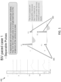
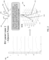
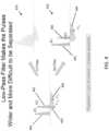
- Figures 1-3 illustrate three possible scenarios: separable, adjacent and partially overlapped ventricular pulses.
- Graph 100 shows the single beat ECG waveforms of leads I, II, V1 and V4 in a sampling window of 100 msec, in which there are clearly two pulses.
- Pulse 1 101 and Pulses 1 102 are each sufficiently distant from one another so that there is no overlap between the two pulses, including their respective recharge pulses. The two pulses are separable, because the V-V interval (corresponding to the P1-P2 interval), is enough to see the two distinct pulses across the leads.
- Graph 200 shows the single beat ECG waveforms of leads I, II, V1 and V4 in a sampling window of 20 msec, in which two pulses cannot clearly be seen.
- the two pulses P1 201 and P2 202, along with their respective recharge pulses P1re 203 and P2re 204, may look like a single pulse followed or led by ripple-like noise, due to the angle between the two pulse vectors and the projection angle to the measurement lead.
- Three dimensional graph 210 provides a graphical illustration of vectors 211 and 212 corresponding to Pulses P1 201 and P2 202, respectively.
- a pace pulse detection algorithm cannot recognize the existence of the second ventricular pulse, the pulse will not be removed, and then the automated diagnostic analysis based on this waveform will not be accurate.
- partially overlapped pulses P1 301 and P2 302 have the recharging wave of the first pulse P1re 303 overlapping with the discharging wave of the second ventricular pulse P2 302.
- P1re 303 and P2 302 will typically show as a single combined pulse or vector Vs 305.
- a pace pulse detection algorithm cannot recognize the existence of the second ventricular pulse, the pulse will not be removed, and then the automated diagnostic analysis based on this waveform will not be accurate.
- a low-Pass filter will typically make a pace pulse wider, so, e.g., two adjacent pulses P1 401 and P2 402 could become unseparated and overlapped on the surface ECG, or the two overlapped pulses could result in more complicated sum of vectors, as shown in graphic 410, for example. Indeed, it can be particularly difficult to separate two pulses subject to a low-Pass filter, as much depends on the details of the specific filter. As shown in graphic 420, for example, similarly to the scenario illustrated in Figure 3 , when no filter is used, the result which is seen is pulse P1 401 followed by a single combined pulse or vector Vs 405, followed by pulse P2 402.
- being able to detect biV pulse is generally considered to be important for an automatic diagnostic ECG system, method and algorithm to interpret an ECG waveform accurately.
- being able to recognize the existence of biV pacemaker using surface ECG will generally help diagnosis.
- exemplary embodiments of a novel system and method which are able to detect biV pulses in the regular format of ECG, so exemplary embodiments of the present invention can be used in post-processing or on a central server.
- exemplary embodiments of the present invention can be incorporated with certain existing (and anticipated future) non-biV pacemaker pulse detection systems and methods with relatively minimal modification.
- non-biV pacemaker pulse detector a non-biV pacemaker pulse detector.
- a non-biV pacemaker pulse detector is provided.
- exemplary embodiments of the non-biV pulse detection system and method will find the onsets of the ventricular pulses and pass the information to the lead-wise biV pulse detector or the vector-based biV pacemaker pulse detector.
- Exemplary VCG transform In accordance with exemplary embodiments of the present invention, exemplary VCG transform system and method are provided. For example, exemplary embodiments of this system and method will transform a multi-lead ECG to a 3-dimensional VectorCardioGraph (VCG) which comprises the values in x, y and z directions, respectively. It is possible to use existing VCG transform methods in accordance with exemplary embodiments of the present invention. For example, it is possible to use, e.g., Levkov transform to convert 12-lead ECG to VCG in accordance with exemplary embodiments of the present invention.
- VCG VectorCardioGraph
- Exemplary lead-wise biventricular pacemaker pulse detector In accordance with exemplary embodiments of the present invention, it is possible that some distant enough biV pulses could be recognized by checking the pulse detection results across all leads. For example, this component looks at the pulse detection result of each single lead to identify the eligible biV paced cases.
- FIG. 5 An exemplary combination block diagram and flow chart of an exemplary embodiment of a biventricular pace pulse detector 500, detection system 500 and detection method 500 in accordance with the present invention is illustrated in Figure 5 , for example.
- the non-biV pulse detector, detection system and/or detection method 511 processes the ECG signal to find the onsets of ventricular pulses at step 512. For some biV paced cases with distant enough ventricular pulses, both ventricular pulses can be detected. Therefore, the lead-wise biV pulse detector 513 will check whether there are two ventricular pulses in one beat (e.g., two pulses near the onset of QRS) at step 514.
- the beat is a biV paced beat, and the process proceeds to step 515 where no further action is needed. Otherwise, the vector-based biV pulse detector 503 will be used to further check the existence of the second ventricular pulse at step 504.
- exemplary embodiments of the vector-based biV pulse detector 503 use 3-D vector features to accomplish this task. Exemplary embodiments of system and method according to the present invention can output the locations and vectors of the detected ventricular pulses as a result.
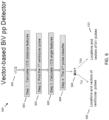
- FIG. 6 illustrates a block diagram of an exemplary vector-based biventricular pacemaker pulse detector 503 in accordance with exemplary embodiments of the present invention.
- this detector 503 is able to find whether there is a pulse separable from the first pulse, so it can be considered a second pulse.
- a 3-D vector typically needs to have significant value and change in amplitude.
- two 3-D vectors typically need to have enough distance in time or in angle from one another.
- the impulse response of the low-pass filter on the first pulse and the recharging wave of the first pulse typically need to be discounted from the selection of a possible biventricular pacemaker pulse.
- the VCG signal 502 of a predefined window size starting from the onset of the detected ventricular pulse of a beat is calculated for the VCG distance features: spatial distance and spatial velocity, which can be defined as illustrated in Figure 7 , for example.
- a major characteristic of a pacemaker pulse is typically a sharp change of amplitude, so minimum threshold values for both spatial distance and spatial velocity can be used for screening pacemaker pulses.
- the vector with spatial velocity larger than its threshold in the first 10 msec for example, the vector with maximal spatial distance is selected as the first pulse in Step 2 602.
- the angle between each vector to the first pulse is calculated in Step 3 603.
- each vector is checked for a possible 2nd ventricular pulse using the classifier of features: spatial distance, velocity, angle and the temporal distance to the first pulse, for example.
- the 1 st v-pulse is the vector with maximum spatial distance (absolute value of amplitude).
- a vector will be classified to decide whether it is the 2 nd v-pulse using VCG feature.
- FIG. 7 shows how the VCG distance features: spatial distance and spatial velocity, can be defined in accordance with exemplary embodiments of the present invention.
- a VCG signal 502 is obtained or calculated and expressed as its vector components.
- spatial distance d k 611 is calculated, e.g., in Step 1 601 illustrated in Figure 6 .
- Spatial velocity v k 713 is calculated as shown in representation 703 of Figure 7 .
- Spatial angle a k 613 is calculated in Step 4 603.
- Graphic 710 provides a graphical representation of the relationship of these vectors.
- Figure 8 illustrates an exemplary embodiment of a pulse classifier 604 in accordance with the present disclosure.
- spatial distance is represented by the top vertical axis 801.
- Spatial angle (degree) against the 1 st pulse is represented by the bottom vertical axis 802.
- Horizontal axis 803 represents the temporal distance to the 1 st pulse.
- Exemplary embodiments of classifier 604 can classify vectors using, as shown in Step 1 810, the spatial distance and the temporal distance to the 1st pulse for the exclusion of the low-pass filter impulse response of the 1 st pulse and vectors without enough amplitude; and, as shown in Step 2 820, the spatial angle against the 1 st pulse and the temporal distance to the 1 st pulse for the exclusion of the recharging wave.
- the main lobe width of the impulse response tends to vary with the low-pass filter.
- the recharging wave generally will be essentially in the opposite direction of the discharging wave with a deviation and generally follow closely after the discharging pulse.
- area 811 of the upper-right quadrant of the graph shown in Figure 8 illustrates the exclusion of impulse response
- area 821 of the lower-right quadrant of the graph shown in Figure 8 illustrates the exclusion of the recharging wave. Accordingly, results falling within areas 811 or 821 are indicative of the 2 nd pulse, while results falling within areas 812 or 822 will not be considered the 2 nd pulse.
- FIG. 9 is an example illustration in accordance with exemplary embodiments of the present invention for adjacent pulses.
- graph 900 shows the single beat ECG waveforms of leads I, II, V1 and V4, in which two pulses cannot clearly be seen.
- two pulses P1 911 and P2 912 are clear in the 3-D VCG 910.
- the 3-D VCG waveforms 921, spatial distance 922, spatial velocity 923 and spatial angle 924 are shown in graphs 920 with the detected two pulses marked within spatial distance graph 922, for example.
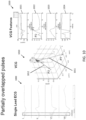
- FIG 10 is an example illustration in accordance with exemplary embodiments of the present invention for partially overlapped pulses.
- graph 1000 shows the single beat ECG waveforms of leads I, II, V1 and V4, in which two pulses cannot clearly be seen.
- two pulses P1 1011 and P2 1012 are clear in the 3-D VCG 1010.
- the 3-D VCG waveforms 1021, spatial distance 1022, spatial velocity 1023 and spatial angle 1024 are shown in graphs 1020 with the detected two pulses marked within spatial distance graph 1022, for example.
- An exemplary system and method according to the present invention were tested on 500sps 12-lead ECGs from patients with non-synchronous biV pacing and showed what can be considered to be excellent detection results.
- 500sps continuous 12-lead ECG were collected from 4 patients with biV pacemakers of various manufacturers, while gradually changing RV-to-LV pacing intervals from 70msec to -70msec and recording ⁇ 30sec for each interval setting.
- the two biV pulses could be as close as 2msec.
- the ECG waveforms were frequently corrupted with highfrequency noise from nearby devices such as the pacemaker programmer.
- the continuous ECG recordings were split into a total of 255 cases of 10sec duration biV paced ECGs, with another 211 cases of 10sec non-biV paced ECGs randomly selected from an existing pacemaker patient database. When more than 50% of the ventricular paced beats were found with biV pulses in a 10sec ECG, the ECG was considered biV paced.
- the exemplary system and method showed a detection sensitivity of 94.1% with a detection specificity of 100%.
- exemplary embodiments of the present invention can be implemented in a wide range of medical devices, including, but not limited to, patient monitors (e.g., ECG monitors), automatic external defibrillators (AEDs) and/or other defibrillators.
- patient monitors e.g., ECG monitors
- AEDs automatic external defibrillators
- exemplary embodiments of the present invention can be specifically implemented in/with virtually any multiple-leads diagnostic ECG analysis program running on cardiograph, patient monitor, telemetry monitor or automatic external defibrillator able to detect biventricular pp on regular or low sampling rate hardware ( ⁇ 5000 sps) and/or virtually any multiple-leads diagnostic ECG analysis program using vector to detect biventricular pp.
- exemplary applications of the present invention include, but are certainly not limited, e.g., Multiple-lead diagnostic ECG analysis, cardiograph, patient monitor, telemetry monitor, AED and other monitor and defibrillators.
- features, elements, components, etc. described in the present disclosure/specification, including the Appendix, and/or depicted in the appended Figures may be implemented in various combinations of hardware and software, and provide functions which may be combined in a single element or multiple elements.
- the functions of the various features, elements, components, etc. shown/illustrated/depicted in the Figure can be provided through the use of dedicated hardware as well as hardware capable of executing software in association with appropriate software.
- the functions can be provided by a single dedicated processor, by a single shared processor, or by a plurality of individual processors, some of which can be shared and/or multiplexed.
- processor or “controller” should not be construed to refer exclusively to hardware capable of executing software, and can implicitly include, without limitation, digital signal processor (“DSP”) hardware, memory (e.g., read only memory (“ROM”) for storing software, random access memory (“RAM”), non-volatile storage, etc.) and virtually any means and/or machine (including hardware, software, firmware, combinations thereof, etc.) which is capable of (and/or configurable) to perform and/or control a process.
- DSP digital signal processor
- ROM read only memory
- RAM random access memory
- non-volatile storage etc.
- machine including hardware, software, firmware, combinations thereof, etc.
- exemplary embodiments of the present invention can take the form of a computer program product accessible from a computer-usable and/or computer-readable storage medium providing program code and/or instructions for use by or in connection with, e.g., a computer or any instruction execution system.
- a computer-usable or computer readable storage medium can be any apparatus that can, e.g., include, store, communicate, propagate or transport the program for use by or in connection with the instruction execution system, apparatus or device.
- Such exemplary medium can be, e.g., an electronic, magnetic, optical, electromagnetic, infrared or semiconductor system (or apparatus or device) or a propagation medium.
- Examples of a computer-readable medium include, e.g., a semiconductor or solid state memory, magnetic tape, a removable computer diskette, a random access memory (RAM), a read-only memory (ROM), flash (drive), a rigid magnetic disk and an optical disk.
- Current examples of optical disks include compact disk - read only memory (CD-ROM), compact disk - read/write (CD-R/W) and DVD.
- corresponding and/or related systems incorporating and/or implementing the device or such as may be used/implemented in a device in accordance with the present disclosure are also contemplated. Further, corresponding and/or related method for manufacturing and/or using a device and/or system in accordance with the present disclosure are also contemplated.
Landscapes
- Health & Medical Sciences (AREA)
- Life Sciences & Earth Sciences (AREA)
- Engineering & Computer Science (AREA)
- Physics & Mathematics (AREA)
- Cardiology (AREA)
- Public Health (AREA)
- Molecular Biology (AREA)
- Veterinary Medicine (AREA)
- General Health & Medical Sciences (AREA)
- Biophysics (AREA)
- Pathology (AREA)
- Biomedical Technology (AREA)
- Heart & Thoracic Surgery (AREA)
- Medical Informatics (AREA)
- Animal Behavior & Ethology (AREA)
- Surgery (AREA)
- Signal Processing (AREA)
- Artificial Intelligence (AREA)
- Psychiatry (AREA)
- Computer Vision & Pattern Recognition (AREA)
- Physiology (AREA)
- Evolutionary Computation (AREA)
- Fuzzy Systems (AREA)
- Mathematical Physics (AREA)
- Electrotherapy Devices (AREA)
Claims (9)
- Vektorbasierter biventrikulärer Schrittmacherimpulsdetektor, umfassend: einen Eingang, der zum Empfangen von Elektrokardiographendaten konfiguriert ist; und ein Prozessor, der konfiguriert ist für: die Daten des Elektrokardiographen in einen dreidimensionalen Vektorkardiographen umwandeln; berechnen (601) VectorCardioGraph-Distanzmerkmale für den dreidimensionalen Vektorkardiographen, wobei die Abstandsmerkmale einen räumlichen Abstand und eine räumliche Geschwindigkeit umfassen, finden (602) eines ersten ventrikulären Pulses, der die Auswahl des Pulses mit einem maximalen räumlichen Abstand unter Pulsen mit räumlichen Geschwindigkeiten größer als einem Schwellenwert umfasst, Berechnen (603) von Vektorkardiograph-Winkelmerkmalen für den dreidimensionalen Vektorkardiographen, wobei die Vektorkardiograph-Winkelmerkmale einen räumlichen Wert umfassen Winkel zum ersten Kammerimpuls, berechnen eines zeitlichen Abstands zum ersten ventrikulären Puls für den dreidimensionalen Vektorkardiographen und bestimmen des Vorhandenseins des biventrikulären Stimulationsimpulses basierend auf den Abstandsmerkmalen des Vektorkardiographen, den Winkelmerkmalen des Vektorkardiographen und der zeitlichen Distanz.
- Detektor nach Anspruch 1, wobei der Detektor außerdem einen Impulsklassifikator umfasst, der so konfiguriert ist, dass er eine Impulsantwort eines Tiefpassfilters zurückweist, um das Vorhandensein des biventrikulären Stimulationsimpulses zu bestimmen.
- Detektor nach Anspruch 1, wobei der Detektor außerdem einen Impulsklassifikator umfasst, der so konfiguriert ist, dass er eine Wiederaufladewelle zurückweist, um das Vorhandensein des biventrikulären Stimulationsimpulses zu bestimmen.
- Detektor nach Anspruch 1, wobei der Detektor außerdem einen Impulsklassifikator umfasst, der so konfiguriert ist, dass er eine Impulsantwort eines Tiefpassfilters und einer Wiederaufladewelle zurückweist, um das Vorhandensein des biventrikulären Stimulationsimpulses zu bestimmen.
- System zum Lokalisieren des Vorhandenseins eines biventrikulären Stimulationsimpulses für einen Elektrokardiographen, umfassend: einen nichtbiventrikulären Pulsdetektor, der so konfiguriert ist, dass er das Einsetzen eines oder mehrerer ventrikulärer Pulse erkennt; einen leitungsweisen biventrikulären Pulsdetektor zur Bestimmung, ob in einem Herzschlag zwei getrennte ventrikuläre Pulse vorhanden sind; einen vektorbasierten biventrikulären Pulsdetektor nach einem der Ansprüche 1 bis 4, der so konfiguriert ist, dass er das Vorhandensein des biventrikulären Stimulationsimpulses ermittelt, wenn der leitungsweise biventrikuläre Pulsdetektor nicht feststellt, dass es in einem Herzschlag zwei getrennte ventrikuläre Pulse gibt;.
- Verfahren zum Lokalisieren des Vorhandenseins eines biventrikulären Stimulationsimpulses für einen Elektrokardiographen mit einem Prozessor, umfassend: umwandeln von Elektrokardiographdaten in einen dreidimensionalen VectorCardioGraph; berechnen (601) der Entfernungsmerkmale des Vektorkardiographen für den dreidimensionalen Vektorkardiographen, wobei die Entfernungsmerkmale eine räumliche Distanz und eine räumliche Geschwindigkeit umfassen; lokalisieren (602) eines ersten ventrikulären Impulses, umfassend das Auswählen eines Impulses mit einem maximalen räumlichen Abstand von Impulsen mit räumlichen Geschwindigkeiten, die größer als ein Schwellenwert sind; berechnen (603) der Winkelmerkmale des Vektorkardiographen für den dreidimensionalen Vektorkardiographen, wobei die Winkelmerkmale des Vektorkardiographen einen räumlichen Winkel zum ersten ventrikulären Puls umfassen; berechnen eines zeitlichen Abstands zum ersten ventrikulären Puls für den dreidimensionalen Vektorkardiographen; bestimmen des Vorhandenseins des biventrikulären Stimulationsimpulses, wobei die Bestimmung auf den Abstandsmerkmalen des Vektorkardiographen, den Winkelmerkmalen des Vektorkardiographen und der zeitlichen Distanz basiert.
- Verfahren nach Anspruch 6, das weiterhin das Erhalten der Elektrokardiographdaten mit einem Elektrokardiographdetektor umfasst.
- Verfahren nach Anspruch 6, wobei die Elektrokardiographdaten zwei benachbarte ventrikuläre Impulse pro Herzschlag umfassen.
- Verfahren nach Anspruch 6, wobei die Elektrokardiographdaten zwei teilweise überlappende ventrikuläre Impulse pro Herzschlag umfassen.
Applications Claiming Priority (2)
| Application Number | Priority Date | Filing Date | Title |
|---|---|---|---|
| US201361812313P | 2013-04-16 | 2013-04-16 | |
| PCT/IB2014/060750 WO2014170832A1 (en) | 2013-04-16 | 2014-04-16 | System and method for biventricular pacemaker pulse detection in surface ecg |
Publications (2)
| Publication Number | Publication Date |
|---|---|
| EP2986207A1 EP2986207A1 (de) | 2016-02-24 |
| EP2986207B1 true EP2986207B1 (de) | 2024-03-20 |
Family
ID=50678249
Family Applications (1)
| Application Number | Title | Priority Date | Filing Date |
|---|---|---|---|
| EP14721986.9A Active EP2986207B1 (de) | 2013-04-16 | 2014-04-16 | System und verfahren zur biventrikulären schrittmacherimpulsdetektion in einer oberflächen-ekg |
Country Status (5)
| Country | Link |
|---|---|
| US (1) | US10085661B2 (de) |
| EP (1) | EP2986207B1 (de) |
| JP (1) | JP6608355B2 (de) |
| CN (1) | CN105338894B (de) |
| WO (1) | WO2014170832A1 (de) |
Families Citing this family (3)
| Publication number | Priority date | Publication date | Assignee | Title |
|---|---|---|---|---|
| EP2986207B1 (de) | 2013-04-16 | 2024-03-20 | Koninklijke Philips N.V. | System und verfahren zur biventrikulären schrittmacherimpulsdetektion in einer oberflächen-ekg |
| CN110584624B (zh) * | 2019-09-18 | 2022-04-01 | 中国科学院微电子研究所 | 基于夹角值的脉搏波特征点识别方法 |
| US12490926B2 (en) * | 2022-04-28 | 2025-12-09 | GE Precision Healthcare LLC | Systems for serial comparison of electrocardiograms |
Family Cites Families (8)
| Publication number | Priority date | Publication date | Assignee | Title |
|---|---|---|---|---|
| US6304772B1 (en) | 1999-08-30 | 2001-10-16 | Ge Medical Systems Information Technologies, Inc. | Method and apparatus for automatically detecting and interpreting paced electrocardiograms |
| US7697977B2 (en) | 2002-11-27 | 2010-04-13 | Cardiac Pacemakers, Inc. | Method and apparatus for determining relative depolarization at multiple cardiac sensing sites |
| US6760615B2 (en) | 2001-10-31 | 2004-07-06 | Medtronic, Inc. | Method and apparatus for discriminating between tachyarrhythmias |
| CN100450435C (zh) * | 2007-02-06 | 2009-01-14 | 赵峰 | 一种向量心电图仪及实现方法 |
| US7907992B2 (en) * | 2007-08-08 | 2011-03-15 | General Electric Company | Method and system for pacemaker pulse detection |
| US7783341B2 (en) * | 2008-01-07 | 2010-08-24 | General Electric Company | Method and apparatus for discerning therapeutic signals from noise in physiological data |
| EP2986207B1 (de) | 2013-04-16 | 2024-03-20 | Koninklijke Philips N.V. | System und verfahren zur biventrikulären schrittmacherimpulsdetektion in einer oberflächen-ekg |
| SMT202400092T1 (it) | 2013-06-13 | 2024-05-14 | Akebia Therapeutics Inc | Composizioni e metodi per il trattamento dell'anemia |
-
2014
- 2014-04-16 EP EP14721986.9A patent/EP2986207B1/de active Active
- 2014-04-16 CN CN201480034048.2A patent/CN105338894B/zh active Active
- 2014-04-16 WO PCT/IB2014/060750 patent/WO2014170832A1/en not_active Ceased
- 2014-04-16 US US14/784,594 patent/US10085661B2/en active Active
- 2014-04-16 JP JP2016508265A patent/JP6608355B2/ja active Active
Also Published As
| Publication number | Publication date |
|---|---|
| US10085661B2 (en) | 2018-10-02 |
| CN105338894A (zh) | 2016-02-17 |
| EP2986207A1 (de) | 2016-02-24 |
| CN105338894B (zh) | 2018-11-30 |
| WO2014170832A1 (en) | 2014-10-23 |
| JP6608355B2 (ja) | 2019-11-20 |
| JP2016521161A (ja) | 2016-07-21 |
| US20160058317A1 (en) | 2016-03-03 |
Similar Documents
| Publication | Publication Date | Title |
|---|---|---|
| De Groot et al. | Critical appraisal of technologies to assess electrical activity during atrial fibrillation: A position paper from the European heart rhythm association and European society of cardiology working group on eCardiology in collaboration with the heart rhythm society, asia pacific heart rhythm society, Latin American heart rhythm society and computing in cardiology | |
| JP5562260B2 (ja) | 心臓活動を正確に分類するための方法および装置 | |
| CN106659900B (zh) | 用于估计心率的具有自相关装置并具有分析装置的可植入医疗装置 | |
| US9436801B2 (en) | Hemodynamic status assessment | |
| JP5237297B2 (ja) | 心拍異常脈動選択及びテンプレート形成 | |
| US8560069B2 (en) | System for cardiac arrhythmia detection | |
| EP2103254B1 (de) | Vorrichtung und computerlesbarer Datenträger zur VS- oder VES-Klassifizierung | |
| US10039464B2 (en) | Phase values and wave front detection for electrophysiological cardiac signals | |
| EP2713866B1 (de) | Klassifizierung von vorhofflimmern mit hilfe eines masses der af komplexität | |
| US11771360B2 (en) | Cardiac monitoring system with normally conducted QRS complex identification | |
| CN110051346B (zh) | 用于基于时间序列和心内及身体表面心电图(ecg)信号形态的心跳分类的装置和方法 | |
| WO2017033140A1 (en) | High/low frequency signal quality evaluations of ecg lead signals | |
| EP3845127B1 (de) | Verfahren und systeme zur schätzung des residualen ekg-rauschpegels und der adaptiven rauschschwelle | |
| US20250099012A1 (en) | Cardiac monitoring system with supraventricular tachycardia (svt) classifications | |
| US20160317816A1 (en) | Optimization of Pacemaker Settings with Electrogram | |
| US10085661B2 (en) | System and method for biventricular pacemaker pulse detection in surface ECG | |
| US20140236034A1 (en) | Method for the detection of subcutanous cardiac signals and a cardiac device for use in detecting subcutaneous cardiac signals | |
| EP3413793B1 (de) | Erkennung von reizimpulsen | |
| EP3571985B1 (de) | Identifizierung von aktivierungen in einem atrialen elektrogramm | |
| US8483814B2 (en) | SCG point pick process for use with multiaxis accelerometers | |
| Gradl et al. | Temporal correction of detected R-peaks in ECG signals: A crucial step to improve QRS detection algorithms | |
| US10405826B2 (en) | Methods and system for tracking heart sounds | |
| US20150342490A1 (en) | Biological signal detecting apparatus and implantable medical device | |
| US9554720B2 (en) | Detection of R-peak point in an electrocardiogram signal | |
| Chien et al. | Vector-based pacemaker pulse detection algorithm for the surface ECG |
Legal Events
| Date | Code | Title | Description |
|---|---|---|---|
| PUAI | Public reference made under article 153(3) epc to a published international application that has entered the european phase |
Free format text: ORIGINAL CODE: 0009012 |
|
| 17P | Request for examination filed |
Effective date: 20151116 |
|
| AK | Designated contracting states |
Kind code of ref document: A1 Designated state(s): AL AT BE BG CH CY CZ DE DK EE ES FI FR GB GR HR HU IE IS IT LI LT LU LV MC MK MT NL NO PL PT RO RS SE SI SK SM TR |
|
| AX | Request for extension of the european patent |
Extension state: BA ME |
|
| DAX | Request for extension of the european patent (deleted) | ||
| STAA | Information on the status of an ep patent application or granted ep patent |
Free format text: STATUS: EXAMINATION IS IN PROGRESS |
|
| 17Q | First examination report despatched |
Effective date: 20200131 |
|
| RAP1 | Party data changed (applicant data changed or rights of an application transferred) |
Owner name: KONINKLIJKE PHILIPS N.V. |
|
| REG | Reference to a national code |
Ref country code: DE Ref legal event code: R079 Ref document number: 602014089728 Country of ref document: DE Free format text: PREVIOUS MAIN CLASS: A61B0005045200 Ipc: A61B0005000000 Ref country code: DE Ref legal event code: R079 Free format text: PREVIOUS MAIN CLASS: A61B0005045200 Ipc: A61B0005000000 |
|
| GRAP | Despatch of communication of intention to grant a patent |
Free format text: ORIGINAL CODE: EPIDOSNIGR1 |
|
| STAA | Information on the status of an ep patent application or granted ep patent |
Free format text: STATUS: GRANT OF PATENT IS INTENDED |
|
| RIC1 | Information provided on ipc code assigned before grant |
Ipc: G16H 50/20 20180101ALI20231003BHEP Ipc: A61B 5/349 20210101ALI20231003BHEP Ipc: A61B 5/341 20210101ALI20231003BHEP Ipc: A61B 5/00 20060101AFI20231003BHEP |
|
| INTG | Intention to grant announced |
Effective date: 20231027 |
|
| GRAS | Grant fee paid |
Free format text: ORIGINAL CODE: EPIDOSNIGR3 |
|
| GRAA | (expected) grant |
Free format text: ORIGINAL CODE: 0009210 |
|
| STAA | Information on the status of an ep patent application or granted ep patent |
Free format text: STATUS: THE PATENT HAS BEEN GRANTED |
|
| AK | Designated contracting states |
Kind code of ref document: B1 Designated state(s): AL AT BE BG CH CY CZ DE DK EE ES FI FR GB GR HR HU IE IS IT LI LT LU LV MC MK MT NL NO PL PT RO RS SE SI SK SM TR |
|
| REG | Reference to a national code |
Ref country code: GB Ref legal event code: FG4D |
|
| REG | Reference to a national code |
Ref country code: CH Ref legal event code: EP |
|
| REG | Reference to a national code |
Ref country code: IE Ref legal event code: FG4D |
|
| REG | Reference to a national code |
Ref country code: DE Ref legal event code: R096 Ref document number: 602014089728 Country of ref document: DE |
|
| REG | Reference to a national code |
Ref country code: DE Ref legal event code: R084 Ref document number: 602014089728 Country of ref document: DE |
|
| PG25 | Lapsed in a contracting state [announced via postgrant information from national office to epo] |
Ref country code: LT Free format text: LAPSE BECAUSE OF FAILURE TO SUBMIT A TRANSLATION OF THE DESCRIPTION OR TO PAY THE FEE WITHIN THE PRESCRIBED TIME-LIMIT Effective date: 20240320 |
|
| REG | Reference to a national code |
Ref country code: LT Ref legal event code: MG9D |
|
| PG25 | Lapsed in a contracting state [announced via postgrant information from national office to epo] |
Ref country code: GR Free format text: LAPSE BECAUSE OF FAILURE TO SUBMIT A TRANSLATION OF THE DESCRIPTION OR TO PAY THE FEE WITHIN THE PRESCRIBED TIME-LIMIT Effective date: 20240621 |
|
| PG25 | Lapsed in a contracting state [announced via postgrant information from national office to epo] |
Ref country code: RS Free format text: LAPSE BECAUSE OF FAILURE TO SUBMIT A TRANSLATION OF THE DESCRIPTION OR TO PAY THE FEE WITHIN THE PRESCRIBED TIME-LIMIT Effective date: 20240620 Ref country code: HR Free format text: LAPSE BECAUSE OF FAILURE TO SUBMIT A TRANSLATION OF THE DESCRIPTION OR TO PAY THE FEE WITHIN THE PRESCRIBED TIME-LIMIT Effective date: 20240320 |
|
| REG | Reference to a national code |
Ref country code: NL Ref legal event code: MP Effective date: 20240320 |
|
| PG25 | Lapsed in a contracting state [announced via postgrant information from national office to epo] |
Ref country code: RS Free format text: LAPSE BECAUSE OF FAILURE TO SUBMIT A TRANSLATION OF THE DESCRIPTION OR TO PAY THE FEE WITHIN THE PRESCRIBED TIME-LIMIT Effective date: 20240620 Ref country code: NO Free format text: LAPSE BECAUSE OF FAILURE TO SUBMIT A TRANSLATION OF THE DESCRIPTION OR TO PAY THE FEE WITHIN THE PRESCRIBED TIME-LIMIT Effective date: 20240620 Ref country code: LT Free format text: LAPSE BECAUSE OF FAILURE TO SUBMIT A TRANSLATION OF THE DESCRIPTION OR TO PAY THE FEE WITHIN THE PRESCRIBED TIME-LIMIT Effective date: 20240320 Ref country code: HR Free format text: LAPSE BECAUSE OF FAILURE TO SUBMIT A TRANSLATION OF THE DESCRIPTION OR TO PAY THE FEE WITHIN THE PRESCRIBED TIME-LIMIT Effective date: 20240320 Ref country code: GR Free format text: LAPSE BECAUSE OF FAILURE TO SUBMIT A TRANSLATION OF THE DESCRIPTION OR TO PAY THE FEE WITHIN THE PRESCRIBED TIME-LIMIT Effective date: 20240621 Ref country code: FI Free format text: LAPSE BECAUSE OF FAILURE TO SUBMIT A TRANSLATION OF THE DESCRIPTION OR TO PAY THE FEE WITHIN THE PRESCRIBED TIME-LIMIT Effective date: 20240320 Ref country code: BG Free format text: LAPSE BECAUSE OF FAILURE TO SUBMIT A TRANSLATION OF THE DESCRIPTION OR TO PAY THE FEE WITHIN THE PRESCRIBED TIME-LIMIT Effective date: 20240320 |
|
| REG | Reference to a national code |
Ref country code: GB Ref legal event code: 746 Effective date: 20240722 |
|
| REG | Reference to a national code |
Ref country code: AT Ref legal event code: MK05 Ref document number: 1667076 Country of ref document: AT Kind code of ref document: T Effective date: 20240320 |
|
| PG25 | Lapsed in a contracting state [announced via postgrant information from national office to epo] |
Ref country code: SE Free format text: LAPSE BECAUSE OF FAILURE TO SUBMIT A TRANSLATION OF THE DESCRIPTION OR TO PAY THE FEE WITHIN THE PRESCRIBED TIME-LIMIT Effective date: 20240320 Ref country code: LV Free format text: LAPSE BECAUSE OF FAILURE TO SUBMIT A TRANSLATION OF THE DESCRIPTION OR TO PAY THE FEE WITHIN THE PRESCRIBED TIME-LIMIT Effective date: 20240320 |
|
| PG25 | Lapsed in a contracting state [announced via postgrant information from national office to epo] |
Ref country code: NL Free format text: LAPSE BECAUSE OF FAILURE TO SUBMIT A TRANSLATION OF THE DESCRIPTION OR TO PAY THE FEE WITHIN THE PRESCRIBED TIME-LIMIT Effective date: 20240320 |
|
| PG25 | Lapsed in a contracting state [announced via postgrant information from national office to epo] |
Ref country code: NL Free format text: LAPSE BECAUSE OF FAILURE TO SUBMIT A TRANSLATION OF THE DESCRIPTION OR TO PAY THE FEE WITHIN THE PRESCRIBED TIME-LIMIT Effective date: 20240320 |
|
| PG25 | Lapsed in a contracting state [announced via postgrant information from national office to epo] |
Ref country code: IS Free format text: LAPSE BECAUSE OF FAILURE TO SUBMIT A TRANSLATION OF THE DESCRIPTION OR TO PAY THE FEE WITHIN THE PRESCRIBED TIME-LIMIT Effective date: 20240720 |
|
| PG25 | Lapsed in a contracting state [announced via postgrant information from national office to epo] |
Ref country code: PT Free format text: LAPSE BECAUSE OF FAILURE TO SUBMIT A TRANSLATION OF THE DESCRIPTION OR TO PAY THE FEE WITHIN THE PRESCRIBED TIME-LIMIT Effective date: 20240722 Ref country code: SM Free format text: LAPSE BECAUSE OF FAILURE TO SUBMIT A TRANSLATION OF THE DESCRIPTION OR TO PAY THE FEE WITHIN THE PRESCRIBED TIME-LIMIT Effective date: 20240320 |
|
| PG25 | Lapsed in a contracting state [announced via postgrant information from national office to epo] |
Ref country code: ES Free format text: LAPSE BECAUSE OF FAILURE TO SUBMIT A TRANSLATION OF THE DESCRIPTION OR TO PAY THE FEE WITHIN THE PRESCRIBED TIME-LIMIT Effective date: 20240320 |
|
| PG25 | Lapsed in a contracting state [announced via postgrant information from national office to epo] |
Ref country code: EE Free format text: LAPSE BECAUSE OF FAILURE TO SUBMIT A TRANSLATION OF THE DESCRIPTION OR TO PAY THE FEE WITHIN THE PRESCRIBED TIME-LIMIT Effective date: 20240320 Ref country code: CZ Free format text: LAPSE BECAUSE OF FAILURE TO SUBMIT A TRANSLATION OF THE DESCRIPTION OR TO PAY THE FEE WITHIN THE PRESCRIBED TIME-LIMIT Effective date: 20240320 |
|
| PG25 | Lapsed in a contracting state [announced via postgrant information from national office to epo] |
Ref country code: AT Free format text: LAPSE BECAUSE OF FAILURE TO SUBMIT A TRANSLATION OF THE DESCRIPTION OR TO PAY THE FEE WITHIN THE PRESCRIBED TIME-LIMIT Effective date: 20240320 |
|
| PG25 | Lapsed in a contracting state [announced via postgrant information from national office to epo] |
Ref country code: PL Free format text: LAPSE BECAUSE OF FAILURE TO SUBMIT A TRANSLATION OF THE DESCRIPTION OR TO PAY THE FEE WITHIN THE PRESCRIBED TIME-LIMIT Effective date: 20240320 |
|
| PG25 | Lapsed in a contracting state [announced via postgrant information from national office to epo] |
Ref country code: SK Free format text: LAPSE BECAUSE OF FAILURE TO SUBMIT A TRANSLATION OF THE DESCRIPTION OR TO PAY THE FEE WITHIN THE PRESCRIBED TIME-LIMIT Effective date: 20240320 |
|
| PG25 | Lapsed in a contracting state [announced via postgrant information from national office to epo] |
Ref country code: SM Free format text: LAPSE BECAUSE OF FAILURE TO SUBMIT A TRANSLATION OF THE DESCRIPTION OR TO PAY THE FEE WITHIN THE PRESCRIBED TIME-LIMIT Effective date: 20240320 Ref country code: SK Free format text: LAPSE BECAUSE OF FAILURE TO SUBMIT A TRANSLATION OF THE DESCRIPTION OR TO PAY THE FEE WITHIN THE PRESCRIBED TIME-LIMIT Effective date: 20240320 Ref country code: RO Free format text: LAPSE BECAUSE OF FAILURE TO SUBMIT A TRANSLATION OF THE DESCRIPTION OR TO PAY THE FEE WITHIN THE PRESCRIBED TIME-LIMIT Effective date: 20240320 Ref country code: PT Free format text: LAPSE BECAUSE OF FAILURE TO SUBMIT A TRANSLATION OF THE DESCRIPTION OR TO PAY THE FEE WITHIN THE PRESCRIBED TIME-LIMIT Effective date: 20240722 Ref country code: PL Free format text: LAPSE BECAUSE OF FAILURE TO SUBMIT A TRANSLATION OF THE DESCRIPTION OR TO PAY THE FEE WITHIN THE PRESCRIBED TIME-LIMIT Effective date: 20240320 Ref country code: IS Free format text: LAPSE BECAUSE OF FAILURE TO SUBMIT A TRANSLATION OF THE DESCRIPTION OR TO PAY THE FEE WITHIN THE PRESCRIBED TIME-LIMIT Effective date: 20240720 Ref country code: ES Free format text: LAPSE BECAUSE OF FAILURE TO SUBMIT A TRANSLATION OF THE DESCRIPTION OR TO PAY THE FEE WITHIN THE PRESCRIBED TIME-LIMIT Effective date: 20240320 Ref country code: EE Free format text: LAPSE BECAUSE OF FAILURE TO SUBMIT A TRANSLATION OF THE DESCRIPTION OR TO PAY THE FEE WITHIN THE PRESCRIBED TIME-LIMIT Effective date: 20240320 Ref country code: CZ Free format text: LAPSE BECAUSE OF FAILURE TO SUBMIT A TRANSLATION OF THE DESCRIPTION OR TO PAY THE FEE WITHIN THE PRESCRIBED TIME-LIMIT Effective date: 20240320 Ref country code: AT Free format text: LAPSE BECAUSE OF FAILURE TO SUBMIT A TRANSLATION OF THE DESCRIPTION OR TO PAY THE FEE WITHIN THE PRESCRIBED TIME-LIMIT Effective date: 20240320 |
|
| REG | Reference to a national code |
Ref country code: CH Ref legal event code: PL |
|
| PG25 | Lapsed in a contracting state [announced via postgrant information from national office to epo] |
Ref country code: IT Free format text: LAPSE BECAUSE OF FAILURE TO SUBMIT A TRANSLATION OF THE DESCRIPTION OR TO PAY THE FEE WITHIN THE PRESCRIBED TIME-LIMIT Effective date: 20240320 |
|
| PG25 | Lapsed in a contracting state [announced via postgrant information from national office to epo] |
Ref country code: LU Free format text: LAPSE BECAUSE OF NON-PAYMENT OF DUE FEES Effective date: 20240416 |
|
| REG | Reference to a national code |
Ref country code: DE Ref legal event code: R097 Ref document number: 602014089728 Country of ref document: DE |
|
| REG | Reference to a national code |
Ref country code: BE Ref legal event code: MM Effective date: 20240430 |
|
| PG25 | Lapsed in a contracting state [announced via postgrant information from national office to epo] |
Ref country code: LU Free format text: LAPSE BECAUSE OF NON-PAYMENT OF DUE FEES Effective date: 20240416 Ref country code: IT Free format text: LAPSE BECAUSE OF FAILURE TO SUBMIT A TRANSLATION OF THE DESCRIPTION OR TO PAY THE FEE WITHIN THE PRESCRIBED TIME-LIMIT Effective date: 20240320 |
|
| PG25 | Lapsed in a contracting state [announced via postgrant information from national office to epo] |
Ref country code: MC Free format text: LAPSE BECAUSE OF FAILURE TO SUBMIT A TRANSLATION OF THE DESCRIPTION OR TO PAY THE FEE WITHIN THE PRESCRIBED TIME-LIMIT Effective date: 20240320 |
|
| PG25 | Lapsed in a contracting state [announced via postgrant information from national office to epo] |
Ref country code: DK Free format text: LAPSE BECAUSE OF FAILURE TO SUBMIT A TRANSLATION OF THE DESCRIPTION OR TO PAY THE FEE WITHIN THE PRESCRIBED TIME-LIMIT Effective date: 20240320 |
|
| PG25 | Lapsed in a contracting state [announced via postgrant information from national office to epo] |
Ref country code: BE Free format text: LAPSE BECAUSE OF NON-PAYMENT OF DUE FEES Effective date: 20240430 |
|
| PLBE | No opposition filed within time limit |
Free format text: ORIGINAL CODE: 0009261 |
|
| STAA | Information on the status of an ep patent application or granted ep patent |
Free format text: STATUS: NO OPPOSITION FILED WITHIN TIME LIMIT |
|
| PG25 | Lapsed in a contracting state [announced via postgrant information from national office to epo] |
Ref country code: MC Free format text: LAPSE BECAUSE OF FAILURE TO SUBMIT A TRANSLATION OF THE DESCRIPTION OR TO PAY THE FEE WITHIN THE PRESCRIBED TIME-LIMIT Effective date: 20240320 Ref country code: DK Free format text: LAPSE BECAUSE OF FAILURE TO SUBMIT A TRANSLATION OF THE DESCRIPTION OR TO PAY THE FEE WITHIN THE PRESCRIBED TIME-LIMIT Effective date: 20240320 Ref country code: BE Free format text: LAPSE BECAUSE OF NON-PAYMENT OF DUE FEES Effective date: 20240430 Ref country code: CH Free format text: LAPSE BECAUSE OF NON-PAYMENT OF DUE FEES Effective date: 20240430 |
|
| 26N | No opposition filed |
Effective date: 20241223 |
|
| PG25 | Lapsed in a contracting state [announced via postgrant information from national office to epo] |
Ref country code: IE Free format text: LAPSE BECAUSE OF NON-PAYMENT OF DUE FEES Effective date: 20240416 |
|
| PG25 | Lapsed in a contracting state [announced via postgrant information from national office to epo] |
Ref country code: SI Free format text: LAPSE BECAUSE OF FAILURE TO SUBMIT A TRANSLATION OF THE DESCRIPTION OR TO PAY THE FEE WITHIN THE PRESCRIBED TIME-LIMIT Effective date: 20240320 |
|
| PGFP | Annual fee paid to national office [announced via postgrant information from national office to epo] |
Ref country code: DE Payment date: 20250428 Year of fee payment: 12 |
|
| PGFP | Annual fee paid to national office [announced via postgrant information from national office to epo] |
Ref country code: FR Payment date: 20250424 Year of fee payment: 12 |
|
| PG25 | Lapsed in a contracting state [announced via postgrant information from national office to epo] |
Ref country code: CY Free format text: LAPSE BECAUSE OF FAILURE TO SUBMIT A TRANSLATION OF THE DESCRIPTION OR TO PAY THE FEE WITHIN THE PRESCRIBED TIME-LIMIT; INVALID AB INITIO Effective date: 20140416 |
|
| PG25 | Lapsed in a contracting state [announced via postgrant information from national office to epo] |
Ref country code: HU Free format text: LAPSE BECAUSE OF FAILURE TO SUBMIT A TRANSLATION OF THE DESCRIPTION OR TO PAY THE FEE WITHIN THE PRESCRIBED TIME-LIMIT; INVALID AB INITIO Effective date: 20140416 |
|
| PGFP | Annual fee paid to national office [announced via postgrant information from national office to epo] |
Ref country code: GB Payment date: 20260319 Year of fee payment: 13 |