EP2985867A1 - Power-feeding device - Google Patents
Power-feeding device Download PDFInfo
- Publication number
- EP2985867A1 EP2985867A1 EP14768899.8A EP14768899A EP2985867A1 EP 2985867 A1 EP2985867 A1 EP 2985867A1 EP 14768899 A EP14768899 A EP 14768899A EP 2985867 A1 EP2985867 A1 EP 2985867A1
- Authority
- EP
- European Patent Office
- Prior art keywords
- power supply
- power
- coil
- amount
- displacement
- Prior art date
- Legal status (The legal status is an assumption and is not a legal conclusion. Google has not performed a legal analysis and makes no representation as to the accuracy of the status listed.)
- Granted
Links
Images

Classifications
-
- B—PERFORMING OPERATIONS; TRANSPORTING
- B60—VEHICLES IN GENERAL
- B60L—PROPULSION OF ELECTRICALLY-PROPELLED VEHICLES; SUPPLYING ELECTRIC POWER FOR AUXILIARY EQUIPMENT OF ELECTRICALLY-PROPELLED VEHICLES; ELECTRODYNAMIC BRAKE SYSTEMS FOR VEHICLES IN GENERAL; MAGNETIC SUSPENSION OR LEVITATION FOR VEHICLES; MONITORING OPERATING VARIABLES OF ELECTRICALLY-PROPELLED VEHICLES; ELECTRIC SAFETY DEVICES FOR ELECTRICALLY-PROPELLED VEHICLES
- B60L53/00—Methods of charging batteries, specially adapted for electric vehicles; Charging stations or on-board charging equipment therefor; Exchange of energy storage elements in electric vehicles
- B60L53/10—Methods of charging batteries, specially adapted for electric vehicles; Charging stations or on-board charging equipment therefor; Exchange of energy storage elements in electric vehicles characterised by the energy transfer between the charging station and the vehicle
- B60L53/12—Inductive energy transfer
- B60L53/122—Circuits or methods for driving the primary coil, e.g. supplying electric power to the coil
-
- B—PERFORMING OPERATIONS; TRANSPORTING
- B60—VEHICLES IN GENERAL
- B60L—PROPULSION OF ELECTRICALLY-PROPELLED VEHICLES; SUPPLYING ELECTRIC POWER FOR AUXILIARY EQUIPMENT OF ELECTRICALLY-PROPELLED VEHICLES; ELECTRODYNAMIC BRAKE SYSTEMS FOR VEHICLES IN GENERAL; MAGNETIC SUSPENSION OR LEVITATION FOR VEHICLES; MONITORING OPERATING VARIABLES OF ELECTRICALLY-PROPELLED VEHICLES; ELECTRIC SAFETY DEVICES FOR ELECTRICALLY-PROPELLED VEHICLES
- B60L53/00—Methods of charging batteries, specially adapted for electric vehicles; Charging stations or on-board charging equipment therefor; Exchange of energy storage elements in electric vehicles
- B60L53/30—Constructional details of charging stations
- B60L53/35—Means for automatic or assisted adjustment of the relative position of charging devices and vehicles
- B60L53/38—Means for automatic or assisted adjustment of the relative position of charging devices and vehicles specially adapted for charging by inductive energy transfer
-
- H—ELECTRICITY
- H02—GENERATION; CONVERSION OR DISTRIBUTION OF ELECTRIC POWER
- H02J—ELECTRIC POWER NETWORKS; CIRCUIT ARRANGEMENTS OR SYSTEMS FOR SUPPLYING OR DISTRIBUTING ELECTRIC POWER; SYSTEMS FOR STORING ELECTRIC ENERGY
- H02J50/00—Circuit arrangements or systems for wireless supply or distribution of electric power
- H02J50/10—Circuit arrangements or systems for wireless supply or distribution of electric power using inductive coupling
-
- H—ELECTRICITY
- H02—GENERATION; CONVERSION OR DISTRIBUTION OF ELECTRIC POWER
- H02J—ELECTRIC POWER NETWORKS; CIRCUIT ARRANGEMENTS OR SYSTEMS FOR SUPPLYING OR DISTRIBUTING ELECTRIC POWER; SYSTEMS FOR STORING ELECTRIC ENERGY
- H02J50/00—Circuit arrangements or systems for wireless supply or distribution of electric power
- H02J50/80—Circuit arrangements or systems for wireless supply or distribution of electric power involving the exchange of data, concerning supply or distribution of electric power, between transmitting devices and receiving devices
-
- H—ELECTRICITY
- H02—GENERATION; CONVERSION OR DISTRIBUTION OF ELECTRIC POWER
- H02J—ELECTRIC POWER NETWORKS; CIRCUIT ARRANGEMENTS OR SYSTEMS FOR SUPPLYING OR DISTRIBUTING ELECTRIC POWER; SYSTEMS FOR STORING ELECTRIC ENERGY
- H02J50/00—Circuit arrangements or systems for wireless supply or distribution of electric power
- H02J50/90—Circuit arrangements or systems for wireless supply or distribution of electric power involving detection or optimisation of position, e.g. alignment
-
- H—ELECTRICITY
- H02—GENERATION; CONVERSION OR DISTRIBUTION OF ELECTRIC POWER
- H02J—ELECTRIC POWER NETWORKS; CIRCUIT ARRANGEMENTS OR SYSTEMS FOR SUPPLYING OR DISTRIBUTING ELECTRIC POWER; SYSTEMS FOR STORING ELECTRIC ENERGY
- H02J7/00—Circuit arrangements for charging or discharging batteries or for supplying loads from batteries
- H02J7/40—Circuit arrangements for charging or discharging batteries or for supplying loads from batteries characterised by the exchange of charge or discharge related data
- H02J7/42—Circuit arrangements for charging or discharging batteries or for supplying loads from batteries characterised by the exchange of charge or discharge related data with electronic devices having internal batteries, e.g. mobile phones
-
- Y—GENERAL TAGGING OF NEW TECHNOLOGICAL DEVELOPMENTS; GENERAL TAGGING OF CROSS-SECTIONAL TECHNOLOGIES SPANNING OVER SEVERAL SECTIONS OF THE IPC; TECHNICAL SUBJECTS COVERED BY FORMER USPC CROSS-REFERENCE ART COLLECTIONS [XRACs] AND DIGESTS
- Y02—TECHNOLOGIES OR APPLICATIONS FOR MITIGATION OR ADAPTATION AGAINST CLIMATE CHANGE
- Y02T—CLIMATE CHANGE MITIGATION TECHNOLOGIES RELATED TO TRANSPORTATION
- Y02T10/00—Road transport of goods or passengers
- Y02T10/60—Other road transportation technologies with climate change mitigation effect
- Y02T10/70—Energy storage systems for electromobility, e.g. batteries
-
- Y—GENERAL TAGGING OF NEW TECHNOLOGICAL DEVELOPMENTS; GENERAL TAGGING OF CROSS-SECTIONAL TECHNOLOGIES SPANNING OVER SEVERAL SECTIONS OF THE IPC; TECHNICAL SUBJECTS COVERED BY FORMER USPC CROSS-REFERENCE ART COLLECTIONS [XRACs] AND DIGESTS
- Y02—TECHNOLOGIES OR APPLICATIONS FOR MITIGATION OR ADAPTATION AGAINST CLIMATE CHANGE
- Y02T—CLIMATE CHANGE MITIGATION TECHNOLOGIES RELATED TO TRANSPORTATION
- Y02T10/00—Road transport of goods or passengers
- Y02T10/60—Other road transportation technologies with climate change mitigation effect
- Y02T10/7072—Electromobility specific charging systems or methods for batteries, ultracapacitors, supercapacitors or double-layer capacitors
-
- Y—GENERAL TAGGING OF NEW TECHNOLOGICAL DEVELOPMENTS; GENERAL TAGGING OF CROSS-SECTIONAL TECHNOLOGIES SPANNING OVER SEVERAL SECTIONS OF THE IPC; TECHNICAL SUBJECTS COVERED BY FORMER USPC CROSS-REFERENCE ART COLLECTIONS [XRACs] AND DIGESTS
- Y02—TECHNOLOGIES OR APPLICATIONS FOR MITIGATION OR ADAPTATION AGAINST CLIMATE CHANGE
- Y02T—CLIMATE CHANGE MITIGATION TECHNOLOGIES RELATED TO TRANSPORTATION
- Y02T90/00—Enabling technologies or technologies with a potential or indirect contribution to GHG emissions mitigation
- Y02T90/10—Technologies relating to charging of electric vehicles
- Y02T90/12—Electric charging stations
-
- Y—GENERAL TAGGING OF NEW TECHNOLOGICAL DEVELOPMENTS; GENERAL TAGGING OF CROSS-SECTIONAL TECHNOLOGIES SPANNING OVER SEVERAL SECTIONS OF THE IPC; TECHNICAL SUBJECTS COVERED BY FORMER USPC CROSS-REFERENCE ART COLLECTIONS [XRACs] AND DIGESTS
- Y02—TECHNOLOGIES OR APPLICATIONS FOR MITIGATION OR ADAPTATION AGAINST CLIMATE CHANGE
- Y02T—CLIMATE CHANGE MITIGATION TECHNOLOGIES RELATED TO TRANSPORTATION
- Y02T90/00—Enabling technologies or technologies with a potential or indirect contribution to GHG emissions mitigation
- Y02T90/10—Technologies relating to charging of electric vehicles
- Y02T90/14—Plug-in electric vehicles
Definitions
- the present invention relates to a power supply apparatus that supplies power to an external power receiving section using an electromagnetic force in a wireless manner.
- wireless power supply systems have been known in which power is supplied while a power supply coil and a power receiving coil are placed facing each other in a wireless manner.
- the position of the power supply coil changes.
- a power supply apparatus is installed on the ground.
- vibration occurs in the power supply apparatus and the position of the power supply coil changes.
- a wireless power supply system to supply power to a portable device is mounted on a mobile unit such as a vehicle, vibration occurs and the position of the power supply coil changes as the mobile unit moves.
- PTL Patent Literature
- the wireless power supply system of PTL 1 performs control of stopping power supply to a power storage apparatus by ECU.
- the power receiving side notifies the power supply side through communication that the power supply stops.
- the technique in PTL 1 can reduce excessive output or an increase in magnetic flux leakage associated with a change in the coupling between the power supply coil and the power receiving coil.
- An object of the present invention is to provide a power supply apparatus capable of minimizing excessive output or an increase in magnetic flux leakage by controlling power supply on the power supply side when an unexpected situation occurs.
- a power supply apparatus supplies power to an external power receiving section in a wireless manner, the power supply apparatus including: a power supply coil that supplies power to a power receiving coil of the power receiving section using an electromagnetic force; and a control section that controls an amount of power supply based on an amount of displacement of the power supply coil when power is supplied from the power supply coil.
- FIG. 1 A configuration of power supply system 10 according to an embodiment of the present invention will be described using FIG. 1 .
- Power supply system 10 is mainly composed of power supply apparatus 100, power receiving apparatus 150 and power supply target 160.
- Power supply apparatus 100 supplies power to power receiving apparatus 150.
- power receiving apparatus 150 supplies power to power supply target 160.
- Power supply target 160 is a load or battery, for example.
- Power supply system 10 is used when charging in a wireless manner a battery which is mounted on a vehicle, when charging in a wireless manner a battery incorporated in an electric device such as a mobile phone or when supplying power to a load such as a motor to drive the load.
- power supply apparatus 100 is installed on the ground such as a parking area and power receiving apparatus 150 is mounted on a vehicle.
- FIG. 1 A configuration of power supply apparatus 100 according to the embodiment of the present invention will be described using FIG. 1 .
- Power supply apparatus 100 is mainly composed of power supply 101, inverter 102, power supply coil 103, power-supply-side communication section 104, acceleration sensor 105, angular velocity sensor 106, and power-supply-side control section 107.
- Power supply 101 supplies power to inverter 102.
- Inverter 102 converts DC power supplied from power supply 101 to AC power under the control of power-supply-side control section 107 and supplies a predetermined amount of AC power to power supply coil 103. Inverter 102 changes the amount of power supplied to power supply coil 103 under the control of power-supply-side control section 107.
- power supply coil 103 Upon receiving power supply from inverter 102, power supply coil 103 supplies power to power receiving coil 154.
- Power supply coil 103 and power receiving coil 154 are planar spiral coils, for example.
- Power supply coil 103 supplies power in the amount of power corresponding to the amount of power supplied from inverter 102.
- power supply coil 103 is magnetically coupled with power receiving coil 154 while facing power receiving coil 154.
- Power supply coil 103 supplies power to power receiving coil 154 according to, for example, an electromagnetic induction scheme or magnetic resonance scheme using an electromagnetic force.
- Power-supply-side communication section 104 exchanges information relating to power supply start or power supply stop with power-receiving-side communication section 153 under the control of power-supply-side control section 107 through wireless communication. Power-supply-side communication section 104 outputs, on the basis of the exchanged information, to power-supply-side control section 107, a signal indicating that power supply is possible or a signal indicating that power supply is not possible.
- Acceleration sensor 105 is installed in the periphery of power supply coil 103. Acceleration sensor 105 detects acceleration of power supply apparatus 100 and outputs the detection value to power-supply-side control section 107. By detecting the acceleration of power supply apparatus 100, acceleration sensor 105 detects acceleration of power supply coil 103. Acceleration sensor 105 is, for example, a triaxial acceleration sensor that can detect acceleration in three mutually orthogonal axial directions.
- Angular velocity sensor 106 is installed in the periphery of power supply coil 103. Angular velocity sensor 106 detects an angular velocity of power supply apparatus 100 and outputs the detection value to power-supply-side control section 107. By detecting the angular velocity of power supply apparatus 100, angular velocity sensor 106 detects an angular velocity of power supply coil 103. Angular velocity sensor 106 is, for example, a triaxial angular velocity sensor that can detect angular velocities in three mutually orthogonal axial directions.
- power-supply-side control section 107 Upon receiving a signal indicating that power supply is possible from power-supply-side communication section 104, power-supply-side control section 107 controls inverter 102 so as to supply the power of power supply 101 to power supply coil 103. Upon receiving a signal indicating that power supply is not possible from power-supply-side communication section 104, power-supply-side control section 107 controls inverter 102 so as to stop the power supply from power supply 101 to power supply coil 103.
- power-supply-side control section 107 During power supply during which power is being supplied from power supply 101 to power supply coil 103, power-supply-side control section 107 accumulates detection values indicating the displacement of power supply coil 103 received from acceleration sensor 105 or angular velocity sensor 106 for a predetermined time, and thereby calculates the amount of displacement of power supply coil 103. Power-supply-side control section 107 controls inverter 102 based on the calculated amount of displacement, and thereby controls the amount of power supply.
- power-supply-side control section 107 controls inverter 102 so that the amount of power supplied to power supply coil 103 becomes small compared to the case where the amount of displacement is smaller than the threshold. Furthermore, when the amount of displacement is equal to or greater than the threshold, power-supply-side control section 107 controls inverter 102 so as to stop power supply to power supply coil 103.
- power-supply-side control section 107 controls inverter 102 so that the amount of power supplied to power supply coil 103 is reduced compared to the case where the amount of displacement is less than threshold A, and power-supply-side control section 107 controls inverter 102 so as to stop the power supply to power supply coil 103 when the amount of displacement is equal to or greater than threshold B.
- stopping power supply means reducing the amount of power supplied from power supply coil 103 to "zero".
- an acceleration sensor and an angular velocity sensor provided for a car navigation apparatus may be also used as acceleration sensor 105 and angular velocity sensor 106.
- FIG. 1 A configuration of power receiving apparatus 150 according to the embodiment of the present invention will be described using FIG. 1 .
- Power receiving apparatus 150 is mainly composed of power-receiving-side control section 151, inverter 152, power-receiving-side communication section 153 and power receiving coil 154.
- power-receiving-side control section 151 Upon receiving a signal indicating that power supply is possible from power-receiving-side communication section 153, power-receiving-side control section 151 controls inverter 152 so as to supply the power received by power receiving coil 154 to power supply target 160. Upon receiving a signal indicating that power supply is not possible from power-receiving-side communication section 153, power-receiving-side control section 151 controls inverter 152 so as to stop supplying the power received by power receiving coil 154 to power supply target 160.
- Inverter 152 converts AC power supplied from power receiving coil 154 to DC power under the control of power-receiving-side control section 151 and supplies the DC power to power supply target 160.
- a rectifier using a diode may also be used to convert AC to DC instead of inverter 152.
- Power-receiving-side communication section 153 exchanges information relating to power supply start or power supply stop with power-supply-side communication section 104 through wireless communication under the control of power-receiving-side control section 151. Based on the exchanged information, power-receiving-side communication section 153 outputs a signal indicating that power supply is possible or a signal indicating that power supply is not possible to power-receiving-side control section 151.
- Power receiving coil 154 receives power from power supply coil 103.
- FIG. 2 An operation of power supply apparatus 100 according to the embodiment of the present invention will be described using FIG. 2 .
- power supply apparatus 100 determines whether or not there is a power-supply-start instruction (step ST201).
- step ST201: No When there is no power-supply-start instruction (step ST201: No), power supply apparatus 100 repeats the process in step ST201.
- step ST201 when there is a power-supply-start instruction (step ST201: Yes), power-supply-side control section 107 determines whether or not power supply is possible by receiving a signal indicating that power supply is possible (step ST202). Upon receiving a signal indicating that power supply is possible, power-supply-side control section 107 determines that power supply is possible and upon receiving a signal indicating that power supply is not possible, power-supply-side control section 107 determines that power supply is not possible.
- step ST202: No power supply apparatus 100 ends the process.
- step ST202 when power supply is possible (step ST202: Yes), power supply apparatus 100 sets a power supply condition (step ST203) and starts power supply (step ST204).
- power-supply-side control section 107 determines whether or not a displacement of power supply coil 103 has been detected (step ST205). Upon receiving a detection value from acceleration sensor 105 or angular velocity sensor 106, power-supply-side control section 107 determines that a displacement has been detected.
- displacement refers to a positional change.
- step ST205 when no displacement of power supply coil 103 has been detected (step ST205: No), power-supply-side control section 107 determines whether or not an overcurrent or overvoltage has occurred (step ST206).
- step ST205 when a displacement of power supply coil 103 has been detected (step ST205: Yes), power-supply-side control section 107 determines whether or not the amount of displacement is equal to or greater than threshold A (step ST207).
- step ST207 When the amount of displacement is less than threshold A (step ST207: No), power supply apparatus 100 proceeds to a process in step ST206.
- step ST207 when the amount of displacement is equal to or greater than threshold A (step ST207: Yes), power-supply-side control section 107 determines whether or not the amount of displacement is equal to or greater than threshold B (threshold B>threshold A) (step ST208).
- step ST208: Yes when the amount of displacement is equal to or greater than threshold B (step ST208: Yes), power-supply-side control section 107 performs control so as to stop power supply from power supply coil 103 (step ST209) and ends the process.
- step ST208 when the amount of displacement is less than threshold B (step ST208: No), power-supply-side control section 107 performs control so that the amount of power supply from power supply coil 103 is reduced compared to the case where the amount of displacement is equal to or greater than threshold B (step ST210), and then proceeds to step ST206.
- step ST206 when an overcurrent or overvoltage has occurred (step ST206: Yes), power supply apparatus 100 performs control so as to stop power supply from power supply coil 103 (step ST209) and ends the process.
- step ST206 determines whether or not a power-supply-stop instruction has been received from the outside (step ST211).
- step ST211: Yes When a power-supply-stop instruction has been received from the outside (step ST211: Yes), power supply apparatus 100 performs control so as to stop power supply from power supply coil 103 (step ST209), and ends the process.
- step ST211: No power supply apparatus 100 returns to the process in step ST205.
- FIG. 3 An arrangement of acceleration sensors 105 according to the embodiment of the present invention will be described using FIG. 3 .
- FIG. 3 illustrates an arrangement of acceleration sensors 105 as seen from a direction in which power supply coil 103 and power receiving coil 154 face each other (direction shown by arrow S1 in FIG. 1 ).
- acceleration sensors 105a, 105b and 105c are arranged in the manner shown in FIG. 3 . That is, acceleration sensors 105a, 105b and 105c are arranged at vertices of triangle E1 respectively.
- power supply apparatus 100 can detect a displacement in all directions of power supply coil 103.
- power supply apparatus 100 can detect the displacement of power supply coil 103 in all directions using one acceleration sensor 105a capable of detecting acceleration in triaxial directions and one angular velocity sensor 106 capable of detecting angular velocities in triaxial directions.
- acceleration sensors 105a, 105b and 105c are arranged at vertices of triangle E1 respectively, the acceleration sensors may also be arranged at vertices of a polygon other than a triangle unless a plurality of acceleration sensors are arranged on a single straight line.
- the acceleration sensors are arranged at vertices of a polygon because when a plurality of acceleration sensors are arranged on a single straight line, if a displacement that rotates around this straight line as the axis of rotation occurs, it is no longer possible to detect the displacement.
- acceleration sensor 105 when acceleration sensor 105 is arranged as shown in FIG. 3 , angular velocity sensor 106 may be omitted.
- any given number of acceleration sensors 105 and angular velocity sensors 106 can be arranged in any given arrangement.
- the number of axes of acceleration sensors 105 and angular velocity sensor 106 may be fewer than three or one of acceleration sensor 105 and angular velocity sensor 106 may be omitted.
- a threshold with which the amount of displacement of power supply coil 103 according to the embodiment of the present invention is compared will be described.
- a mechanical restricting section for restricting a displacement of power supply coil 103 is provided or a mechanical restricting section for restricting a relative displacement between power supply coil 103 and power receiving coil 154 is provided separately, it is possible to make a threshold to be compared with the amount of displacement of power supply coil 103 with respect to the direction in which the restricting section is provided greater than a threshold to be compared with the amount of displacement of power supply coil 103 with respect to another direction.
- Examples of the mechanical restricting section include a member that comes into contact with power supply apparatus 100 when power supply apparatus 100 displaces to prevent further a displacement of power supply apparatus 100 or a member that restricts a relative displacement between power supply coil 103 and power receiving coil 154.
- the present embodiment controls power supply on the power supply side when an unexpected situation occurs and can thereby minimize excessive output or an increase in magnetic flux leakage.
- the present embodiment arranges the acceleration sensors at vertices of a polygon respectively, and can thereby detect a displacement of power supply coil 103 in all detections.
- the present embodiment uses triaxial gyroscopes as angular velocity sensors 106, and can thereby reduce the number of sensors for detecting a displacement of power supply coil 103 and reduce the manufacturing cost.
- the present embodiment reduces the amount of power supply when the amount of displacement of power supply coil 103 is equal to or greater than threshold A but less than threshold B, and can thereby reduce the frequency with which power supply is stopped compared to a case where power supply is immediately stopped.
- the present embodiment reduces the amount of power supply when the amount of displacement of power supply coil 103 is equal to or greater than threshold A but less than threshold B, but the power supply may be immediately stopped when the amount of displacement of power supply coil 103 is equal to or greater than threshold A.
- the present embodiment detects a displacement of power supply coil 103 using acceleration sensor 105 or angular velocity sensor 106, but any given sensor can be used if this can detect a displacement of power supply coil 103.
- the installation location of the power supply apparatus is not limited to the ground but may be a mobile unit such as an automobile, railway vehicle, aircraft, ship or playground equipment.
- the power receiving side may be a small electronic device such as a portable device.
- the power supply coil and the power receiving coil are assumed to be planar spiral coils, but any coil other than the spiral coil may be used if this is a coil which can transmit and/or receive power, and a solenoid coil may be used, for example.
- the present invention is suitable for use in a power supply apparatus that supplies power to an external power receiving section using an electromagnetic force in a wireless manner.
Landscapes
- Engineering & Computer Science (AREA)
- Power Engineering (AREA)
- Computer Networks & Wireless Communication (AREA)
- Transportation (AREA)
- Mechanical Engineering (AREA)
- Charge And Discharge Circuits For Batteries Or The Like (AREA)
- Electric Propulsion And Braking For Vehicles (AREA)
Abstract
Description
- The present invention relates to a power supply apparatus that supplies power to an external power receiving section using an electromagnetic force in a wireless manner.
- Conventionally, wireless power supply systems have been known in which power is supplied while a power supply coil and a power receiving coil are placed facing each other in a wireless manner. In such wireless power supply systems, when vibration is added to the power supply side during power supply due to an earthquake or the like, the position of the power supply coil changes.
- For example, in a wireless power supply system that supplies power to a power storage apparatus mounted on a vehicle such as an electric vehicle, a power supply apparatus is installed on the ground. In this case, when an earthquake occurs or when a large vehicle passes by, vibration occurs in the power supply apparatus and the position of the power supply coil changes. When a wireless power supply system to supply power to a portable device is mounted on a mobile unit such as a vehicle, vibration occurs and the position of the power supply coil changes as the mobile unit moves.
- When the position of the power supply coil changes during power supply, coupling between the power supply coil and the power receiving coil changes, causing excessive output or an increase in magnetic flux leakage.
- Conventionally, wireless power supply systems configured to stop a charging section mounted on the vehicle when an unexpected situation such as an earthquake occurs have been known (e.g., FIG. 10 in Patent Literature (hereinafter, referred to as "PTL") 1). When an unexpected situation occurs, the wireless power supply system of PTL 1 performs control of stopping power supply to a power storage apparatus by ECU. When resumption of the power supply is impossible, the power receiving side notifies the power supply side through communication that the power supply stops. Thus, the technique in PTL 1 can reduce excessive output or an increase in magnetic flux leakage associated with a change in the coupling between the power supply coil and the power receiving coil.
- PTL 1
WO 2010/137145 - However, according to PTL 1, since the power receiving side performs control of stopping power supply, it takes a considerable time until the power supply stops after an unexpected situation occurs. Thus, there is a problem that it is not possible to reduce excessive output or an increase in magnetic flux leakage for this time period.
- An object of the present invention is to provide a power supply apparatus capable of minimizing excessive output or an increase in magnetic flux leakage by controlling power supply on the power supply side when an unexpected situation occurs.
- A power supply apparatus according to the present invention supplies power to an external power receiving section in a wireless manner, the power supply apparatus including: a power supply coil that supplies power to a power receiving coil of the power receiving section using an electromagnetic force; and a control section that controls an amount of power supply based on an amount of displacement of the power supply coil when power is supplied from the power supply coil.
- According to the present invention, it is possible to minimize excessive output or an increase in magnetic flux leakage by controlling the amount of power supply on the power supply side when an unexpected situation occurs.
-
-
FIG. 1 is a block diagram illustrating a configuration of a power supply system according to an embodiment of the present invention; -
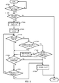
FIG. 2 is a flowchart illustrating an operation of a power supply apparatus according to an embodiment of the present invention; and -
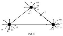
FIG. 3 is a diagram illustrating an arrangement of acceleration sensors according to the embodiment of the present invention. - Hereinafter, an embodiment of the present invention will be described in detail with reference to the accompanying drawings.
- A configuration of
power supply system 10 according to an embodiment of the present invention will be described usingFIG. 1 . -
Power supply system 10 is mainly composed ofpower supply apparatus 100,power receiving apparatus 150 andpower supply target 160. -
Power supply apparatus 100 supplies power topower receiving apparatus 150. - By receiving power supply from
power supply apparatus 100,power receiving apparatus 150 supplies power topower supply target 160. -
Power supply target 160 is a load or battery, for example. -
Power supply system 10 is used when charging in a wireless manner a battery which is mounted on a vehicle, when charging in a wireless manner a battery incorporated in an electric device such as a mobile phone or when supplying power to a load such as a motor to drive the load. When a vehicle-mounted battery is charged in a wireless manner,power supply apparatus 100 is installed on the ground such as a parking area andpower receiving apparatus 150 is mounted on a vehicle. - A configuration of
power supply apparatus 100 according to the embodiment of the present invention will be described usingFIG. 1 . -
Power supply apparatus 100 is mainly composed ofpower supply 101, inverter 102,power supply coil 103, power-supply-side communication section 104,acceleration sensor 105,angular velocity sensor 106, and power-supply-side control section 107. -
Power supply 101 supplies power to inverter 102. - Inverter 102 converts DC power supplied from
power supply 101 to AC power under the control of power-supply-side control section 107 and supplies a predetermined amount of AC power topower supply coil 103. Inverter 102 changes the amount of power supplied topower supply coil 103 under the control of power-supply-side control section 107. - Upon receiving power supply from inverter 102,
power supply coil 103 supplies power topower receiving coil 154.Power supply coil 103 andpower receiving coil 154 are planar spiral coils, for example.Power supply coil 103 supplies power in the amount of power corresponding to the amount of power supplied from inverter 102. When supplying power,power supply coil 103 is magnetically coupled withpower receiving coil 154 while facingpower receiving coil 154.Power supply coil 103 supplies power topower receiving coil 154 according to, for example, an electromagnetic induction scheme or magnetic resonance scheme using an electromagnetic force. - Power-supply-
side communication section 104 exchanges information relating to power supply start or power supply stop with power-receiving-side communication section 153 under the control of power-supply-side control section 107 through wireless communication. Power-supply-side communication section 104 outputs, on the basis of the exchanged information, to power-supply-side control section 107, a signal indicating that power supply is possible or a signal indicating that power supply is not possible. -
Acceleration sensor 105 is installed in the periphery ofpower supply coil 103.Acceleration sensor 105 detects acceleration ofpower supply apparatus 100 and outputs the detection value to power-supply-side control section 107. By detecting the acceleration ofpower supply apparatus 100,acceleration sensor 105 detects acceleration ofpower supply coil 103.Acceleration sensor 105 is, for example, a triaxial acceleration sensor that can detect acceleration in three mutually orthogonal axial directions. -
Angular velocity sensor 106 is installed in the periphery ofpower supply coil 103.Angular velocity sensor 106 detects an angular velocity ofpower supply apparatus 100 and outputs the detection value to power-supply-side control section 107. By detecting the angular velocity ofpower supply apparatus 100,angular velocity sensor 106 detects an angular velocity ofpower supply coil 103.Angular velocity sensor 106 is, for example, a triaxial angular velocity sensor that can detect angular velocities in three mutually orthogonal axial directions. - Upon receiving a signal indicating that power supply is possible from power-supply-
side communication section 104, power-supply-side control section 107 controls inverter 102 so as to supply the power ofpower supply 101 topower supply coil 103. Upon receiving a signal indicating that power supply is not possible from power-supply-side communication section 104, power-supply-side control section 107 controls inverter 102 so as to stop the power supply frompower supply 101 topower supply coil 103. - During power supply during which power is being supplied from
power supply 101 topower supply coil 103, power-supply-side control section 107 accumulates detection values indicating the displacement ofpower supply coil 103 received fromacceleration sensor 105 orangular velocity sensor 106 for a predetermined time, and thereby calculates the amount of displacement ofpower supply coil 103. Power-supply-side control section 107 controls inverter 102 based on the calculated amount of displacement, and thereby controls the amount of power supply. - More specifically, when the amount of displacement is equal to or greater than a threshold, power-supply-
side control section 107 controls inverter 102 so that the amount of power supplied topower supply coil 103 becomes small compared to the case where the amount of displacement is smaller than the threshold. Furthermore, when the amount of displacement is equal to or greater than the threshold, power-supply-side control section 107 controls inverter 102 so as to stop power supply topower supply coil 103. Furthermore, when the amount of displacement is equal to or greater than threshold A but less than threshold B (threshold B>threshold A), power-supply-side control section 107 controls inverter 102 so that the amount of power supplied topower supply coil 103 is reduced compared to the case where the amount of displacement is less than threshold A, and power-supply-side control section 107 controls inverter 102 so as to stop the power supply topower supply coil 103 when the amount of displacement is equal to or greater than threshold B. Here, stopping power supply means reducing the amount of power supplied frompower supply coil 103 to "zero". - Note that, for example, when charging
system 10 is mounted on a vehicle, an acceleration sensor and an angular velocity sensor provided for a car navigation apparatus may be also used asacceleration sensor 105 andangular velocity sensor 106. - A configuration of
power receiving apparatus 150 according to the embodiment of the present invention will be described usingFIG. 1 . -
Power receiving apparatus 150 is mainly composed of power-receiving-side control section 151,inverter 152, power-receiving-side communication section 153 andpower receiving coil 154. - Upon receiving a signal indicating that power supply is possible from power-receiving-
side communication section 153, power-receiving-side control section 151controls inverter 152 so as to supply the power received bypower receiving coil 154 topower supply target 160. Upon receiving a signal indicating that power supply is not possible from power-receiving-side communication section 153, power-receiving-side control section 151controls inverter 152 so as to stop supplying the power received bypower receiving coil 154 topower supply target 160. -
Inverter 152 converts AC power supplied frompower receiving coil 154 to DC power under the control of power-receiving-side control section 151 and supplies the DC power topower supply target 160. Note that, a rectifier using a diode, for example, may also be used to convert AC to DC instead ofinverter 152. - Power-receiving-
side communication section 153 exchanges information relating to power supply start or power supply stop with power-supply-side communication section 104 through wireless communication under the control of power-receiving-side control section 151. Based on the exchanged information, power-receiving-side communication section 153 outputs a signal indicating that power supply is possible or a signal indicating that power supply is not possible to power-receiving-side control section 151. -
Power receiving coil 154 receives power frompower supply coil 103. - An operation of
power supply apparatus 100 according to the embodiment of the present invention will be described usingFIG. 2 . - First,
power supply apparatus 100 determines whether or not there is a power-supply-start instruction (step ST201). - When there is no power-supply-start instruction (step ST201: No),
power supply apparatus 100 repeats the process in step ST201. - On the other hand, in
power supply apparatus 100, when there is a power-supply-start instruction (step ST201: Yes), power-supply-side control section 107 determines whether or not power supply is possible by receiving a signal indicating that power supply is possible (step ST202). Upon receiving a signal indicating that power supply is possible, power-supply-side control section 107 determines that power supply is possible and upon receiving a signal indicating that power supply is not possible, power-supply-side control section 107 determines that power supply is not possible. - When power supply is not possible (step ST202: No),
power supply apparatus 100 ends the process. - On the other hand, when power supply is possible (step ST202: Yes),
power supply apparatus 100 sets a power supply condition (step ST203) and starts power supply (step ST204). - Next, in
power supply apparatus 100, power-supply-side control section 107 determines whether or not a displacement ofpower supply coil 103 has been detected (step ST205). Upon receiving a detection value fromacceleration sensor 105 orangular velocity sensor 106, power-supply-side control section 107 determines that a displacement has been detected. Here, the term "displacement" refers to a positional change. - In
power supply apparatus 100, when no displacement ofpower supply coil 103 has been detected (step ST205: No), power-supply-side control section 107 determines whether or not an overcurrent or overvoltage has occurred (step ST206). - On the other hand, in
power supply apparatus 100, when a displacement ofpower supply coil 103 has been detected (step ST205: Yes), power-supply-side control section 107 determines whether or not the amount of displacement is equal to or greater than threshold A (step ST207). - When the amount of displacement is less than threshold A (step ST207: No),
power supply apparatus 100 proceeds to a process in step ST206. - On the other hand, in
power supply apparatus 100, when the amount of displacement is equal to or greater than threshold A (step ST207: Yes), power-supply-side control section 107 determines whether or not the amount of displacement is equal to or greater than threshold B (threshold B>threshold A) (step ST208). - In
power supply apparatus 100, when the amount of displacement is equal to or greater than threshold B (step ST208: Yes), power-supply-side control section 107 performs control so as to stop power supply from power supply coil 103 (step ST209) and ends the process. - On the other hand, in
power supply apparatus 100, when the amount of displacement is less than threshold B (step ST208: No), power-supply-side control section 107 performs control so that the amount of power supply frompower supply coil 103 is reduced compared to the case where the amount of displacement is equal to or greater than threshold B (step ST210), and then proceeds to step ST206. - In step ST206 when an overcurrent or overvoltage has occurred (step ST206: Yes),
power supply apparatus 100 performs control so as to stop power supply from power supply coil 103 (step ST209) and ends the process. - On the other hand, when no overcurrent or overvoltage has occurred in step ST206 (step ST206: No),
power supply apparatus 100 determines whether or not a power-supply-stop instruction has been received from the outside (step ST211). - When a power-supply-stop instruction has been received from the outside (step ST211: Yes),
power supply apparatus 100 performs control so as to stop power supply from power supply coil 103 (step ST209), and ends the process. - On the other hand, when no power-supply-stop instruction has been received (step ST211: No),
power supply apparatus 100 returns to the process in step ST205. - Note that in
FIG. 2 , when the amount of displacement is equal to or greater than threshold B, the power supply is stopped to end the process, but power supply may be resumed when the amount of displacement is less than threshold B after stopping the power supply. - An arrangement of
acceleration sensors 105 according to the embodiment of the present invention will be described usingFIG. 3 . -
FIG. 3 illustrates an arrangement ofacceleration sensors 105 as seen from a direction in whichpower supply coil 103 andpower receiving coil 154 face each other (direction shown by arrow S1 inFIG. 1 ). - For example, in the case where one
acceleration sensor 105 detects a displacement ofpower supply coil 103, in a rotation aroundacceleration sensor 105, the position ofpower supply coil 103 with respect topower receiving coil 154 is shifted regardless of acceleration "zero" and the state of coupling betweenpower supply coil 103 andpower receiving coil 154 changes. - In order to solve the above problem, three
acceleration sensors FIG. 3 . That is,acceleration sensors power supply apparatus 100 can detect a displacement in all directions ofpower supply coil 103. - Note that instead of arranging three
acceleration sensors FIG. 3 ,power supply apparatus 100 can detect the displacement ofpower supply coil 103 in all directions using oneacceleration sensor 105a capable of detecting acceleration in triaxial directions and oneangular velocity sensor 106 capable of detecting angular velocities in triaxial directions. - Although three
acceleration sensors - Moreover, when
acceleration sensor 105 is arranged as shown inFIG. 3 ,angular velocity sensor 106 may be omitted. - As long as displacements and rotations in triaxial directions of
power supply coil 103 can be detected, any given number ofacceleration sensors 105 andangular velocity sensors 106 can be arranged in any given arrangement. - When a mechanical restricting section for restricting a displacement in a specific one or multiple directions is provided separately, and a displacement in a direction in which the section for restricting the displacement thereby need not be detected, or when the influence of the displacement on the power supply is sufficiently small, the number of axes of
acceleration sensors 105 andangular velocity sensor 106 may be fewer than three or one ofacceleration sensor 105 andangular velocity sensor 106 may be omitted. - A threshold with which the amount of displacement of
power supply coil 103 according to the embodiment of the present invention is compared will be described. - When a mechanical restricting section for restricting a displacement of
power supply coil 103 is provided or a mechanical restricting section for restricting a relative displacement betweenpower supply coil 103 andpower receiving coil 154 is provided separately, it is possible to make a threshold to be compared with the amount of displacement ofpower supply coil 103 with respect to the direction in which the restricting section is provided greater than a threshold to be compared with the amount of displacement ofpower supply coil 103 with respect to another direction. - Examples of the mechanical restricting section include a member that comes into contact with
power supply apparatus 100 whenpower supply apparatus 100 displaces to prevent further a displacement ofpower supply apparatus 100 or a member that restricts a relative displacement betweenpower supply coil 103 andpower receiving coil 154. - Thus, when
power supply coil 103 displaces in the direction in which the restricting section is provided, or when the relative displacement betweenpower supply coil 103 andpower receiving coil 154 by provision of the restricting section is small, and in a situation in which continuation of power supply poses no problem, it is possible to prevent a reduction in the amount of power supply or the power supply from being stopped. - The present embodiment controls power supply on the power supply side when an unexpected situation occurs and can thereby minimize excessive output or an increase in magnetic flux leakage.
- The present embodiment arranges the acceleration sensors at vertices of a polygon respectively, and can thereby detect a displacement of
power supply coil 103 in all detections. - The present embodiment uses triaxial gyroscopes as
angular velocity sensors 106, and can thereby reduce the number of sensors for detecting a displacement ofpower supply coil 103 and reduce the manufacturing cost. - The present embodiment reduces the amount of power supply when the amount of displacement of
power supply coil 103 is equal to or greater than threshold A but less than threshold B, and can thereby reduce the frequency with which power supply is stopped compared to a case where power supply is immediately stopped. - The present embodiment reduces the amount of power supply when the amount of displacement of
power supply coil 103 is equal to or greater than threshold A but less than threshold B, but the power supply may be immediately stopped when the amount of displacement ofpower supply coil 103 is equal to or greater than threshold A. - The present embodiment detects a displacement of
power supply coil 103 usingacceleration sensor 105 orangular velocity sensor 106, but any given sensor can be used if this can detect a displacement ofpower supply coil 103. - In the present embodiment, the installation location of the power supply apparatus is not limited to the ground but may be a mobile unit such as an automobile, railway vehicle, aircraft, ship or playground equipment. In this case, for example, the power receiving side may be a small electronic device such as a portable device.
- In the present embodiment, the power supply coil and the power receiving coil are assumed to be planar spiral coils, but any coil other than the spiral coil may be used if this is a coil which can transmit and/or receive power, and a solenoid coil may be used, for example.
- The disclosure of
Japanese Patent Application No. 2013-060080, filed on March 22, 2013 - The present invention is suitable for use in a power supply apparatus that supplies power to an external power receiving section using an electromagnetic force in a wireless manner.
-
- 10 Power supply system
- 100 Power supply apparatus
- 101 Power supply
- 102 Inverter
- 103 Power supply coil
- 104 Power-supply-side communication section
- 105 Acceleration sensor
- 106 Angular velocity sensor
- 107 Power-supply-side control section
- 150 Power receiving apparatus
- 151 Power-receiving-side control section
- 152 Inverter
- 153 Power-receiving-side communication section
- 154 Power receiving coil
- 160 Power supply target
Claims (7)
- A power supply apparatus that supplies power to an external power receiving section in a wireless manner, the power supply apparatus comprising:a power supply coil that supplies power to a power receiving coil of the power receiving section using an electromagnetic force; anda control section that controls an amount of power supply based on an amount of displacement of the power supply coil when power is supplied from the power supply coil.
- The power supply apparatus according to claim 1, wherein, when the amount of displacement is equal to or greater than a threshold, the control section reduces the amount of power supply compared to a case where the amount of displacement is less than the threshold.
- The power supply apparatus according to claim 1, wherein, when the amount of displacement is equal to or greater than a threshold, the control section sets the amount of power supply to "zero."
- The power supply apparatus according to claim 1, wherein, when the amount of displacement is equal to or greater than a first threshold, the control section reduces the amount of power supply to a predetermined amount of power supply compared to a case where the amount of displacement is less than the first threshold, the predetermined amount being greater than zero, and the control section reduces the amount of power supply to "zero" when the amount of displacement is equal to or greater than a second threshold which is greater than the first threshold.
- The power supply apparatus according to claim 1, further comprising a detection section that detects a displacement of the power supply coil, wherein the control section calculates the amount of displacement from an accumulation of the displacements detected by the detection section for a predetermined time.
- The power supply apparatus according to claim 5, wherein the detection section detects acceleration of the power supply coil as the displacement.
- The power supply apparatus according to claim 5, wherein the detection section detects an angular velocity of the power supply coil as the displacement.
Applications Claiming Priority (2)
| Application Number | Priority Date | Filing Date | Title |
|---|---|---|---|
| JP2013060080A JP6167395B2 (en) | 2013-03-22 | 2013-03-22 | Power supply device |
| PCT/JP2014/001606 WO2014148055A1 (en) | 2013-03-22 | 2014-03-20 | Power-feeding device |
Publications (3)
| Publication Number | Publication Date |
|---|---|
| EP2985867A1 true EP2985867A1 (en) | 2016-02-17 |
| EP2985867A4 EP2985867A4 (en) | 2016-03-02 |
| EP2985867B1 EP2985867B1 (en) | 2020-04-29 |
Family
ID=51579752
Family Applications (1)
| Application Number | Title | Priority Date | Filing Date |
|---|---|---|---|
| EP14768899.8A Active EP2985867B1 (en) | 2013-03-22 | 2014-03-20 | Power-feeding device |
Country Status (5)
| Country | Link |
|---|---|
| US (3) | US9973040B2 (en) |
| EP (1) | EP2985867B1 (en) |
| JP (1) | JP6167395B2 (en) |
| CN (2) | CN105144543B (en) |
| WO (1) | WO2014148055A1 (en) |
Families Citing this family (7)
| Publication number | Priority date | Publication date | Assignee | Title |
|---|---|---|---|---|
| JP6076315B2 (en) | 2014-11-05 | 2017-02-08 | 本田技研工業株式会社 | Contactless charging system |
| KR102529747B1 (en) * | 2016-05-23 | 2023-05-08 | 삼성에스디아이 주식회사 | Wireless charging device and charging method thereof |
| CN106541844B (en) * | 2016-10-26 | 2020-04-10 | 深圳市沃尔核材股份有限公司 | Wireless charging coil alignment method, device and system |
| US11584240B2 (en) | 2017-04-19 | 2023-02-21 | Arnold Chase | Intelligent vehicle charging station |
| US10988042B1 (en) | 2018-10-12 | 2021-04-27 | Arnold Chase | Vehicle charging system |
| US11485246B1 (en) | 2021-04-05 | 2022-11-01 | Arnold Chase | Individualized vehicular charging mat |
| US12024039B2 (en) | 2021-12-07 | 2024-07-02 | Arnold Chase | Vehicle self-centered charging system |
Family Cites Families (49)
| Publication number | Priority date | Publication date | Assignee | Title |
|---|---|---|---|---|
| JP2002538706A (en) * | 1999-02-26 | 2002-11-12 | コーニンクレッカ フィリップス エレクトロニクス エヌ ヴィ | Remote control unit and system |
| JP2005110412A (en) * | 2003-09-30 | 2005-04-21 | Sharp Corp | Power supply system |
| JP2005110409A (en) * | 2003-09-30 | 2005-04-21 | Sharp Corp | Power supply system |
| US7233137B2 (en) | 2003-09-30 | 2007-06-19 | Sharp Kabushiki Kaisha | Power supply system |
| JP4000122B2 (en) * | 2004-02-27 | 2007-10-31 | 株式会社東芝 | Wireless communication system and wireless communication method |
| US7605496B2 (en) * | 2004-05-11 | 2009-10-20 | Access Business Group International Llc | Controlling inductive power transfer systems |
| KR100853889B1 (en) * | 2005-07-29 | 2008-08-25 | 엘에스전선 주식회사 | Contactless rechargeable batteries and chargers, battery charging sets comprising them, and charging control methods |
| JP5121307B2 (en) * | 2007-05-28 | 2013-01-16 | ソニーモバイルコミュニケーションズ株式会社 | Non-contact power transmission coil unit, portable terminal, power transmission device, and non-contact power transmission system |
| JP5285418B2 (en) * | 2008-12-24 | 2013-09-11 | 株式会社豊田自動織機 | Resonant non-contact power supply device |
| JP2010183814A (en) * | 2009-02-09 | 2010-08-19 | Toyota Industries Corp | Non-contact power transmitter |
| JP4883247B2 (en) | 2009-05-28 | 2012-02-22 | トヨタ自動車株式会社 | Charging system, vehicle and charging system control method |
| KR101373208B1 (en) * | 2009-05-28 | 2014-03-14 | 한국전자통신연구원 | Electric device, wireless power transmission device and power transmission method thereof |
| CN101908755A (en) * | 2009-06-02 | 2010-12-08 | 鸿富锦精密工业(深圳)有限公司 | Battery over-discharge protection device |
| TWI389416B (en) * | 2010-05-31 | 2013-03-11 | 富達通科技股份有限公司 | Power transmission method of high power wireless inductive power supply |
| US9125134B2 (en) * | 2010-08-23 | 2015-09-01 | Qualcomm Incorporated | Proximity agent based out of band communication for femtocell operation |
| JP2012049923A (en) * | 2010-08-27 | 2012-03-08 | Kyocera Corp | Radio communication equipment, communication system, and control method |
| JP5083480B2 (en) * | 2010-12-01 | 2012-11-28 | トヨタ自動車株式会社 | Non-contact power supply facility, vehicle, and control method for non-contact power supply system |
| JP2012165635A (en) * | 2011-02-08 | 2012-08-30 | Tdk Corp | Wireless power reception device and wireless power transmission system |
| US8716999B2 (en) * | 2011-02-10 | 2014-05-06 | Draker, Inc. | Dynamic frequency and pulse-width modulation of dual-mode switching power controllers in photovoltaic arrays |
| US8929809B2 (en) * | 2011-03-22 | 2015-01-06 | Radeum, Inc. | Techniques for wireless communication of proximity based content |
| US9623257B2 (en) * | 2011-04-18 | 2017-04-18 | Medtronic, Inc. | Recharge tuning techniques for an implantable device |
| WO2012157570A1 (en) * | 2011-05-18 | 2012-11-22 | 日本電気株式会社 | Wireless transmission device and wireless transmission method |
| JP2012257381A (en) * | 2011-06-09 | 2012-12-27 | Panasonic Corp | On-vehicle non-contact charging device |
| CN103782483A (en) * | 2011-06-30 | 2014-05-07 | 矢崎总业株式会社 | Power feeding system design method and power feeding system |
| US9379571B2 (en) * | 2011-07-11 | 2016-06-28 | Delphi Technologies, Inc. | Electrical charging system having energy coupling arrangement for wireless energy transmission therebetween |
| KR101241091B1 (en) * | 2011-08-19 | 2013-03-11 | 연세대학교 산학협력단 | Wireless power transmission system using position alignment of inductor and device for detecting alignment error |
| SG11201400409XA (en) * | 2011-09-07 | 2014-04-28 | Solace Power Inc | Wireless electric field power transmission system and method |
| US9444289B2 (en) * | 2011-09-09 | 2016-09-13 | Lg Electronics Inc. | Wireless power system and resonant frequency changing method thereof |
| US9812902B2 (en) * | 2011-09-13 | 2017-11-07 | Samsung Electronics Co., Ltd. | Wireless electromagnetic receiver and wireless power transfer system |
| JP2013063004A (en) * | 2011-09-15 | 2013-04-04 | Panasonic Corp | Power supply device and vehicle power reception device |
| KR101781650B1 (en) * | 2011-10-04 | 2017-09-26 | 삼성전자주식회사 | Wireless power multi-charge method and power transmitter |
| US9450648B2 (en) * | 2011-10-13 | 2016-09-20 | Integrated Device Technology, Inc. | Apparatus, system, and method for detecting a foreign object in an inductive wireless power transfer system |
| WO2013061441A1 (en) * | 2011-10-27 | 2013-05-02 | トヨタ自動車株式会社 | Non-contact power receiving apparatus, non-contact power transmitting apparatus, and non-contact power transmitting/receiving system |
| US9079043B2 (en) * | 2011-11-21 | 2015-07-14 | Thoratec Corporation | Transcutaneous power transmission utilizing non-planar resonators |
| KR101332224B1 (en) * | 2011-12-28 | 2013-11-25 | 주식회사 스파콘 | Wireless power transmission apparatus |
| JP2013143574A (en) * | 2012-01-06 | 2013-07-22 | Fujitsu Mobile Communications Ltd | Radio communication terminal device and radio communication terminal device control method |
| WO2013114576A1 (en) * | 2012-01-31 | 2013-08-08 | 富士通株式会社 | Power transmission device, power transmission system, and power transmission method |
| US9558883B2 (en) * | 2012-05-02 | 2017-01-31 | Samsung Electronics Co., Ltd | Power transmitter and method for controlling power transmission |
| JP2014027753A (en) * | 2012-07-25 | 2014-02-06 | Mitsubishi Electric Corp | Solar light power generation system |
| TWI593207B (en) * | 2012-09-11 | 2017-07-21 | 通路實業集團國際公司 | Wireless power transmitter and remote device for receiving wireless power and control method thereof |
| US9362776B2 (en) * | 2012-11-27 | 2016-06-07 | Qualcomm Incorporated | Wireless charging systems and methods |
| KR101979459B1 (en) * | 2012-12-03 | 2019-05-16 | 엘에스전선 주식회사 | Wireless Power Transmission System, Wireless Power Receiving Apparatus and Wireless Power Receiving Method |
| US9831705B2 (en) * | 2012-12-12 | 2017-11-28 | Qualcomm Incorporated | Resolving communcations in a wireless power system with co-located transmitters |
| WO2014147818A1 (en) * | 2013-03-22 | 2014-09-25 | トヨタ自動車株式会社 | Power transmission device, power receiving device, vehicle, and contactless power supply system |
| EP3005522B1 (en) * | 2013-06-04 | 2018-04-11 | Koninklijke Philips N.V. | Wireless inductive power transfer |
| CN103399654A (en) * | 2013-06-28 | 2013-11-20 | 东北大学 | Self-powered wireless mouse and method |
| WO2016151889A1 (en) * | 2015-03-23 | 2016-09-29 | 三菱電機株式会社 | Bidirectional non-contact power supply device and bidirectional non-contact power supply system |
| JP6120116B2 (en) * | 2015-10-02 | 2017-04-26 | パナソニックIpマネジメント株式会社 | Wireless power transmission system |
| US10666055B2 (en) * | 2015-12-17 | 2020-05-26 | Garrity Power Services Llc | Portable power system |
-
2013
- 2013-03-22 JP JP2013060080A patent/JP6167395B2/en active Active
-
2014
- 2014-03-20 EP EP14768899.8A patent/EP2985867B1/en active Active
- 2014-03-20 US US14/778,425 patent/US9973040B2/en active Active
- 2014-03-20 CN CN201480016744.0A patent/CN105144543B/en active Active
- 2014-03-20 WO PCT/JP2014/001606 patent/WO2014148055A1/en not_active Ceased
- 2014-03-20 CN CN201810945138.7A patent/CN108964224B/en active Active
-
2018
- 2018-04-10 US US15/949,476 patent/US10381885B2/en active Active
-
2019
- 2019-06-28 US US16/456,911 patent/US10766373B2/en active Active
Also Published As
| Publication number | Publication date |
|---|---|
| CN105144543B (en) | 2018-09-21 |
| CN108964224B (en) | 2022-07-12 |
| EP2985867B1 (en) | 2020-04-29 |
| US20190319497A1 (en) | 2019-10-17 |
| JP6167395B2 (en) | 2017-07-26 |
| US9973040B2 (en) | 2018-05-15 |
| US20180226837A1 (en) | 2018-08-09 |
| US10766373B2 (en) | 2020-09-08 |
| US10381885B2 (en) | 2019-08-13 |
| CN105144543A (en) | 2015-12-09 |
| CN108964224A (en) | 2018-12-07 |
| WO2014148055A1 (en) | 2014-09-25 |
| JP2014187775A (en) | 2014-10-02 |
| US20160276872A1 (en) | 2016-09-22 |
| EP2985867A4 (en) | 2016-03-02 |
Similar Documents
| Publication | Publication Date | Title |
|---|---|---|
| US10766373B2 (en) | Power-feeding device | |
| JP6919244B2 (en) | Vehicle control unit | |
| US9088173B2 (en) | Control apparatus, control method of supply apparatus, and supply system | |
| US10562396B2 (en) | Parking assistance apparatus and system | |
| KR102406107B1 (en) | Wireless charging system for electric vehicle with adjustable flux angle | |
| EP3009296A1 (en) | Vehicle electricity supply system | |
| EP3089323B1 (en) | Non-contact power transmission device | |
| US10017065B2 (en) | Power reception device and vehicle including the same | |
| EP3103673A1 (en) | Parking assistance device and parking assistance method | |
| US12384259B2 (en) | Ground power supplying apparatus, method for controlling ground power supplying apparatus, and nontransitory computer recording medium | |
| US12459379B2 (en) | Vehicle, ground power supplying apparatus, and noncontact power supplying system | |
| JP2014183715A (en) | Power receiver | |
| EP2985872A1 (en) | Power supplying device, power receiving device, and power supplying system | |
| US20170163093A1 (en) | Resonant type power transmission system and resonance type power transmission device | |
| JP6897371B2 (en) | Vehicle and power transmission system | |
| EP3251886A1 (en) | Parking assistance device and parking assistance method | |
| US20200047636A1 (en) | Charging system | |
| JP2013009479A (en) | Power supply device, power receiving device, mobile, power charging system, and power supply method | |
| US20220402392A1 (en) | Vehicle, method of control of power reception of vehicle, and nontransitory computer recording medium | |
| JP2014183621A (en) | Power receiver | |
| WO2013122052A1 (en) | Non-contact power transmitting apparatus | |
| JP6622523B2 (en) | Mobile device and non-contact power transmission system | |
| KR20140048502A (en) | The battery charging method of wireless charging type electric vehicle | |
| JP2020099146A (en) | Contactless power supply communication device | |
| HK40004046A (en) | Charging system |
Legal Events
| Date | Code | Title | Description |
|---|---|---|---|
| PUAI | Public reference made under article 153(3) epc to a published international application that has entered the european phase |
Free format text: ORIGINAL CODE: 0009012 |
|
| 17P | Request for examination filed |
Effective date: 20150921 |
|
| AK | Designated contracting states |
Kind code of ref document: A1 Designated state(s): AL AT BE BG CH CY CZ DE DK EE ES FI FR GB GR HR HU IE IS IT LI LT LU LV MC MK MT NL NO PL PT RO RS SE SI SK SM TR |
|
| AX | Request for extension of the european patent |
Extension state: BA ME |
|
| A4 | Supplementary search report drawn up and despatched |
Effective date: 20160201 |
|
| RIC1 | Information provided on ipc code assigned before grant |
Ipc: H02J 7/02 20060101ALI20160304BHEP Ipc: H02J 50/90 20160101ALI20160304BHEP Ipc: B60L 11/18 20060101AFI20160304BHEP |
|
| DAX | Request for extension of the european patent (deleted) | ||
| STAA | Information on the status of an ep patent application or granted ep patent |
Free format text: STATUS: EXAMINATION IS IN PROGRESS |
|
| 17Q | First examination report despatched |
Effective date: 20190103 |
|
| REG | Reference to a national code |
Ref country code: DE Ref legal event code: R079 Ref document number: 602014064553 Country of ref document: DE Free format text: PREVIOUS MAIN CLASS: H02J0050000000 Ipc: H02J0007020000 |
|
| RIC1 | Information provided on ipc code assigned before grant |
Ipc: H02J 50/90 20160101ALI20190829BHEP Ipc: H02J 7/02 20160101AFI20190829BHEP Ipc: B60L 53/12 20190101ALI20190829BHEP Ipc: H02J 50/10 20160101ALI20190829BHEP Ipc: H02J 50/80 20160101ALI20190829BHEP Ipc: B60L 53/38 20190101ALI20190829BHEP |
|
| GRAP | Despatch of communication of intention to grant a patent |
Free format text: ORIGINAL CODE: EPIDOSNIGR1 |
|
| STAA | Information on the status of an ep patent application or granted ep patent |
Free format text: STATUS: GRANT OF PATENT IS INTENDED |
|
| INTG | Intention to grant announced |
Effective date: 20191021 |
|
| GRAS | Grant fee paid |
Free format text: ORIGINAL CODE: EPIDOSNIGR3 |
|
| GRAA | (expected) grant |
Free format text: ORIGINAL CODE: 0009210 |
|
| STAA | Information on the status of an ep patent application or granted ep patent |
Free format text: STATUS: THE PATENT HAS BEEN GRANTED |
|
| AK | Designated contracting states |
Kind code of ref document: B1 Designated state(s): AL AT BE BG CH CY CZ DE DK EE ES FI FR GB GR HR HU IE IS IT LI LT LU LV MC MK MT NL NO PL PT RO RS SE SI SK SM TR |
|
| REG | Reference to a national code |
Ref country code: GB Ref legal event code: FG4D |
|
| REG | Reference to a national code |
Ref country code: CH Ref legal event code: EP |
|
| REG | Reference to a national code |
Ref country code: AT Ref legal event code: REF Ref document number: 1264757 Country of ref document: AT Kind code of ref document: T Effective date: 20200515 |
|
| REG | Reference to a national code |
Ref country code: DE Ref legal event code: R096 Ref document number: 602014064553 Country of ref document: DE |
|
| REG | Reference to a national code |
Ref country code: IE Ref legal event code: FG4D |
|
| REG | Reference to a national code |
Ref country code: NL Ref legal event code: MP Effective date: 20200429 |
|
| REG | Reference to a national code |
Ref country code: LT Ref legal event code: MG4D |
|
| PG25 | Lapsed in a contracting state [announced via postgrant information from national office to epo] |
Ref country code: NO Free format text: LAPSE BECAUSE OF FAILURE TO SUBMIT A TRANSLATION OF THE DESCRIPTION OR TO PAY THE FEE WITHIN THE PRESCRIBED TIME-LIMIT Effective date: 20200729 Ref country code: FI Free format text: LAPSE BECAUSE OF FAILURE TO SUBMIT A TRANSLATION OF THE DESCRIPTION OR TO PAY THE FEE WITHIN THE PRESCRIBED TIME-LIMIT Effective date: 20200429 Ref country code: LT Free format text: LAPSE BECAUSE OF FAILURE TO SUBMIT A TRANSLATION OF THE DESCRIPTION OR TO PAY THE FEE WITHIN THE PRESCRIBED TIME-LIMIT Effective date: 20200429 Ref country code: GR Free format text: LAPSE BECAUSE OF FAILURE TO SUBMIT A TRANSLATION OF THE DESCRIPTION OR TO PAY THE FEE WITHIN THE PRESCRIBED TIME-LIMIT Effective date: 20200730 Ref country code: SE Free format text: LAPSE BECAUSE OF FAILURE TO SUBMIT A TRANSLATION OF THE DESCRIPTION OR TO PAY THE FEE WITHIN THE PRESCRIBED TIME-LIMIT Effective date: 20200429 Ref country code: PT Free format text: LAPSE BECAUSE OF FAILURE TO SUBMIT A TRANSLATION OF THE DESCRIPTION OR TO PAY THE FEE WITHIN THE PRESCRIBED TIME-LIMIT Effective date: 20200831 Ref country code: IS Free format text: LAPSE BECAUSE OF FAILURE TO SUBMIT A TRANSLATION OF THE DESCRIPTION OR TO PAY THE FEE WITHIN THE PRESCRIBED TIME-LIMIT Effective date: 20200829 |
|
| REG | Reference to a national code |
Ref country code: AT Ref legal event code: MK05 Ref document number: 1264757 Country of ref document: AT Kind code of ref document: T Effective date: 20200429 |
|
| PG25 | Lapsed in a contracting state [announced via postgrant information from national office to epo] |
Ref country code: HR Free format text: LAPSE BECAUSE OF FAILURE TO SUBMIT A TRANSLATION OF THE DESCRIPTION OR TO PAY THE FEE WITHIN THE PRESCRIBED TIME-LIMIT Effective date: 20200429 Ref country code: RS Free format text: LAPSE BECAUSE OF FAILURE TO SUBMIT A TRANSLATION OF THE DESCRIPTION OR TO PAY THE FEE WITHIN THE PRESCRIBED TIME-LIMIT Effective date: 20200429 Ref country code: BG Free format text: LAPSE BECAUSE OF FAILURE TO SUBMIT A TRANSLATION OF THE DESCRIPTION OR TO PAY THE FEE WITHIN THE PRESCRIBED TIME-LIMIT Effective date: 20200729 Ref country code: LV Free format text: LAPSE BECAUSE OF FAILURE TO SUBMIT A TRANSLATION OF THE DESCRIPTION OR TO PAY THE FEE WITHIN THE PRESCRIBED TIME-LIMIT Effective date: 20200429 |
|
| PG25 | Lapsed in a contracting state [announced via postgrant information from national office to epo] |
Ref country code: AL Free format text: LAPSE BECAUSE OF FAILURE TO SUBMIT A TRANSLATION OF THE DESCRIPTION OR TO PAY THE FEE WITHIN THE PRESCRIBED TIME-LIMIT Effective date: 20200429 Ref country code: NL Free format text: LAPSE BECAUSE OF FAILURE TO SUBMIT A TRANSLATION OF THE DESCRIPTION OR TO PAY THE FEE WITHIN THE PRESCRIBED TIME-LIMIT Effective date: 20200429 |
|
| PG25 | Lapsed in a contracting state [announced via postgrant information from national office to epo] |
Ref country code: ES Free format text: LAPSE BECAUSE OF FAILURE TO SUBMIT A TRANSLATION OF THE DESCRIPTION OR TO PAY THE FEE WITHIN THE PRESCRIBED TIME-LIMIT Effective date: 20200429 Ref country code: CZ Free format text: LAPSE BECAUSE OF FAILURE TO SUBMIT A TRANSLATION OF THE DESCRIPTION OR TO PAY THE FEE WITHIN THE PRESCRIBED TIME-LIMIT Effective date: 20200429 Ref country code: AT Free format text: LAPSE BECAUSE OF FAILURE TO SUBMIT A TRANSLATION OF THE DESCRIPTION OR TO PAY THE FEE WITHIN THE PRESCRIBED TIME-LIMIT Effective date: 20200429 Ref country code: RO Free format text: LAPSE BECAUSE OF FAILURE TO SUBMIT A TRANSLATION OF THE DESCRIPTION OR TO PAY THE FEE WITHIN THE PRESCRIBED TIME-LIMIT Effective date: 20200429 Ref country code: EE Free format text: LAPSE BECAUSE OF FAILURE TO SUBMIT A TRANSLATION OF THE DESCRIPTION OR TO PAY THE FEE WITHIN THE PRESCRIBED TIME-LIMIT Effective date: 20200429 Ref country code: SM Free format text: LAPSE BECAUSE OF FAILURE TO SUBMIT A TRANSLATION OF THE DESCRIPTION OR TO PAY THE FEE WITHIN THE PRESCRIBED TIME-LIMIT Effective date: 20200429 Ref country code: IT Free format text: LAPSE BECAUSE OF FAILURE TO SUBMIT A TRANSLATION OF THE DESCRIPTION OR TO PAY THE FEE WITHIN THE PRESCRIBED TIME-LIMIT Effective date: 20200429 Ref country code: DK Free format text: LAPSE BECAUSE OF FAILURE TO SUBMIT A TRANSLATION OF THE DESCRIPTION OR TO PAY THE FEE WITHIN THE PRESCRIBED TIME-LIMIT Effective date: 20200429 |
|
| REG | Reference to a national code |
Ref country code: DE Ref legal event code: R097 Ref document number: 602014064553 Country of ref document: DE |
|
| PG25 | Lapsed in a contracting state [announced via postgrant information from national office to epo] |
Ref country code: SK Free format text: LAPSE BECAUSE OF FAILURE TO SUBMIT A TRANSLATION OF THE DESCRIPTION OR TO PAY THE FEE WITHIN THE PRESCRIBED TIME-LIMIT Effective date: 20200429 Ref country code: PL Free format text: LAPSE BECAUSE OF FAILURE TO SUBMIT A TRANSLATION OF THE DESCRIPTION OR TO PAY THE FEE WITHIN THE PRESCRIBED TIME-LIMIT Effective date: 20200429 |
|
| PLBE | No opposition filed within time limit |
Free format text: ORIGINAL CODE: 0009261 |
|
| STAA | Information on the status of an ep patent application or granted ep patent |
Free format text: STATUS: NO OPPOSITION FILED WITHIN TIME LIMIT |
|
| 26N | No opposition filed |
Effective date: 20210201 |
|
| PG25 | Lapsed in a contracting state [announced via postgrant information from national office to epo] |
Ref country code: SI Free format text: LAPSE BECAUSE OF FAILURE TO SUBMIT A TRANSLATION OF THE DESCRIPTION OR TO PAY THE FEE WITHIN THE PRESCRIBED TIME-LIMIT Effective date: 20200429 |
|
| PG25 | Lapsed in a contracting state [announced via postgrant information from national office to epo] |
Ref country code: MC Free format text: LAPSE BECAUSE OF FAILURE TO SUBMIT A TRANSLATION OF THE DESCRIPTION OR TO PAY THE FEE WITHIN THE PRESCRIBED TIME-LIMIT Effective date: 20200429 |
|
| REG | Reference to a national code |
Ref country code: CH Ref legal event code: PL |
|
| GBPC | Gb: european patent ceased through non-payment of renewal fee |
Effective date: 20210320 |
|
| REG | Reference to a national code |
Ref country code: BE Ref legal event code: MM Effective date: 20210331 |
|
| PG25 | Lapsed in a contracting state [announced via postgrant information from national office to epo] |
Ref country code: FR Free format text: LAPSE BECAUSE OF NON-PAYMENT OF DUE FEES Effective date: 20210331 Ref country code: GB Free format text: LAPSE BECAUSE OF NON-PAYMENT OF DUE FEES Effective date: 20210320 Ref country code: IE Free format text: LAPSE BECAUSE OF NON-PAYMENT OF DUE FEES Effective date: 20210320 Ref country code: CH Free format text: LAPSE BECAUSE OF NON-PAYMENT OF DUE FEES Effective date: 20210331 Ref country code: LU Free format text: LAPSE BECAUSE OF NON-PAYMENT OF DUE FEES Effective date: 20210320 Ref country code: LI Free format text: LAPSE BECAUSE OF NON-PAYMENT OF DUE FEES Effective date: 20210331 |
|
| PG25 | Lapsed in a contracting state [announced via postgrant information from national office to epo] |
Ref country code: BE Free format text: LAPSE BECAUSE OF NON-PAYMENT OF DUE FEES Effective date: 20210331 |
|
| PG25 | Lapsed in a contracting state [announced via postgrant information from national office to epo] |
Ref country code: HU Free format text: LAPSE BECAUSE OF FAILURE TO SUBMIT A TRANSLATION OF THE DESCRIPTION OR TO PAY THE FEE WITHIN THE PRESCRIBED TIME-LIMIT; INVALID AB INITIO Effective date: 20140320 |
|
| PG25 | Lapsed in a contracting state [announced via postgrant information from national office to epo] |
Ref country code: CY Free format text: LAPSE BECAUSE OF FAILURE TO SUBMIT A TRANSLATION OF THE DESCRIPTION OR TO PAY THE FEE WITHIN THE PRESCRIBED TIME-LIMIT Effective date: 20200429 |
|
| REG | Reference to a national code |
Ref country code: DE Ref legal event code: R081 Ref document number: 602014064553 Country of ref document: DE Owner name: PANASONIC AUTOMOTIVE SYSTEMS CO., LTD., YOKOHA, JP Free format text: FORMER OWNER: PANASONIC INTELLECTUAL PROPERTY MANAGEMENT CO., LTD, OSAKA-SHI, OSAKA, JP |
|
| PG25 | Lapsed in a contracting state [announced via postgrant information from national office to epo] |
Ref country code: MK Free format text: LAPSE BECAUSE OF FAILURE TO SUBMIT A TRANSLATION OF THE DESCRIPTION OR TO PAY THE FEE WITHIN THE PRESCRIBED TIME-LIMIT Effective date: 20200429 |
|
| PG25 | Lapsed in a contracting state [announced via postgrant information from national office to epo] |
Ref country code: MT Free format text: LAPSE BECAUSE OF FAILURE TO SUBMIT A TRANSLATION OF THE DESCRIPTION OR TO PAY THE FEE WITHIN THE PRESCRIBED TIME-LIMIT Effective date: 20200429 |
|
| PG25 | Lapsed in a contracting state [announced via postgrant information from national office to epo] |
Ref country code: TR Free format text: LAPSE BECAUSE OF FAILURE TO SUBMIT A TRANSLATION OF THE DESCRIPTION OR TO PAY THE FEE WITHIN THE PRESCRIBED TIME-LIMIT Effective date: 20200429 |
|
| PGFP | Annual fee paid to national office [announced via postgrant information from national office to epo] |
Ref country code: DE Payment date: 20260319 Year of fee payment: 13 |