EP2985828A1 - Fuel cell system and fuel cell system control method - Google Patents
Fuel cell system and fuel cell system control method Download PDFInfo
- Publication number
- EP2985828A1 EP2985828A1 EP13881894.3A EP13881894A EP2985828A1 EP 2985828 A1 EP2985828 A1 EP 2985828A1 EP 13881894 A EP13881894 A EP 13881894A EP 2985828 A1 EP2985828 A1 EP 2985828A1
- Authority
- EP
- European Patent Office
- Prior art keywords
- fuel cell
- fuel
- cell system
- fuel gas
- command
- Prior art date
- Legal status (The legal status is an assumption and is not a legal conclusion. Google has not performed a legal analysis and makes no representation as to the accuracy of the status listed.)
- Granted
Links
Images

Classifications
-
- H—ELECTRICITY
- H01—ELECTRIC ELEMENTS
- H01M—PROCESSES OR MEANS, e.g. BATTERIES, FOR THE DIRECT CONVERSION OF CHEMICAL ENERGY INTO ELECTRICAL ENERGY
- H01M8/00—Fuel cells; Manufacture thereof
- H01M8/04—Auxiliary arrangements, e.g. for control of pressure or for circulation of fluids
- H01M8/04298—Processes for controlling fuel cells or fuel cell systems
- H01M8/04694—Processes for controlling fuel cells or fuel cell systems characterised by variables to be controlled
- H01M8/04746—Pressure; Flow
- H01M8/04753—Pressure; Flow of fuel cell reactants
-
- H—ELECTRICITY
- H01—ELECTRIC ELEMENTS
- H01M—PROCESSES OR MEANS, e.g. BATTERIES, FOR THE DIRECT CONVERSION OF CHEMICAL ENERGY INTO ELECTRICAL ENERGY
- H01M8/00—Fuel cells; Manufacture thereof
- H01M8/04—Auxiliary arrangements, e.g. for control of pressure or for circulation of fluids
- H01M8/04298—Processes for controlling fuel cells or fuel cell systems
- H01M8/04313—Processes for controlling fuel cells or fuel cell systems characterised by the detection or assessment of variables; characterised by the detection or assessment of failure or abnormal function
- H01M8/04537—Electric variables
- H01M8/04544—Voltage
- H01M8/04559—Voltage of fuel cell stacks
-
- Y—GENERAL TAGGING OF NEW TECHNOLOGICAL DEVELOPMENTS; GENERAL TAGGING OF CROSS-SECTIONAL TECHNOLOGIES SPANNING OVER SEVERAL SECTIONS OF THE IPC; TECHNICAL SUBJECTS COVERED BY FORMER USPC CROSS-REFERENCE ART COLLECTIONS [XRACs] AND DIGESTS
- Y02—TECHNOLOGIES OR APPLICATIONS FOR MITIGATION OR ADAPTATION AGAINST CLIMATE CHANGE
- Y02E—REDUCTION OF GREENHOUSE GAS [GHG] EMISSIONS, RELATED TO ENERGY GENERATION, TRANSMISSION OR DISTRIBUTION
- Y02E60/00—Enabling technologies; Technologies with a potential or indirect contribution to GHG emissions mitigation
- Y02E60/30—Hydrogen technology
- Y02E60/50—Fuel cells
Definitions
- the present invention relates to a fuel cell system and a control method for the fuel cell system.
- a fuel cell is a device that converts the energy produced when generating water through a reaction between fuel gas containing hydrogen and oxygen, to produce electric energy. Because flammable gas is used as the fuel gas in the fuel cell, the system using the fuel cell needs to be designed to prevent leakage of the fuel gas.
- Patent Literature 1 discloses a technique related to leakage of fuel gas.
- the technique disclosed in Patent Literature 1 measures an output voltage of a fuel cell during suspension of supply of fuel gas to the fuel cell, and determines the presence/absence of leakage of the fuel gas based on the result of the measurement.
- Patent Literature 1 Japanese Patent Application Laid-open No. 2009-146658
- Patent Literature 1 In order to enhance the safety of a fuel cell, supply of fuel gas needs to be stopped when the fuel gas leaks during the generation of electricity by the fuel cell. Unfortunately, the technique disclosed in Patent Literature 1 theoretically is not capable of detecting leakage of fuel gas while the fuel cell generates electricity.
- An object of the present invention is to provide a fuel cell system that is capable of suspending the supply of fuel gas when the fuel gas leaks, even during the generation of electricity by a fuel cell, and a control method for the fuel cell system.
- a fuel cell system has a fuel cell, a voltage measurement unit, a comment output unit, and an interrupter.
- the fuel cell receives fuel gas through a pipe.
- the voltage measurement unit measures an output voltage of the fuel cell.
- the command output unit outputs an interruption command when a measurement result of the voltage measurement unit is equal to or less than a reference value during the generation of electricity by the fuel cell.
- the interrupter is provided in the pipe described above and interrupts the supply of the fuel gas to the fuel cell in response to the interruption command.
- the present invention can suspends the supply of fuel gas when the fuel gas leaks, even during the generation of electricity by a fuel cell.
- Fig. 1 is a block diagram showing a functional configuration of a fuel cell system 10 according to a first embodiment.
- the fuel cell system 10 according to the present embodiment has a fuel cell 150, a voltage measurement unit 182, a command output unit 180, and an interrupter 110.
- the fuel cell 150 receives fuel gas through a pipe and generates electricity using the received fuel gas and oxygen-containing gas (e.g., air).
- the voltage measurement unit 182 measures an output voltage of the fuel cell 150.
- the command output unit 180 outputs an interruption command when the measurement result of the voltage measurement unit 182 becomes equal to or less than a reference value during the generation of electricity by the fuel cell 150.
- the interrupter 110 is provided in the pipe and interrupts the supply of fuel gas to the fuel cell 150 in response to the interruption command output by the command output unit 180.
- the interrupter 110 is, for example, a valve.
- the voltage measurement unit 182 outputs the output voltage of the fuel cell 150 to the command output unit 180 only while the fuel cell 150 generates electricity. Because outputs of the fuel cell 150 are not stable immediately after the beginning of the operation of the fuel cell 150, the voltage measurement unit 182 starts outputting the output voltage of the fuel cell 150 after a lapse of a certain period of time (e.g., at least one minute) from the start of the operation of the fuel cell 150. Such a process can be realized by controlling the operation of the voltage measurement unit 182 using a timer.
- the command output unit 180 is configured with an electric circuit, and does not execute software processing.
- the command output unit 180 is configured with, for example, a relay circuit. Therefore, the command output unit 180 is highly reliable and complies with a CE marking.
- the command output unit 180 outputs an interruption command when the measurement result of the voltage measurement unit 182 becomes equal to or less than the reference value throughout a predetermined certain period of time (e.g., at least one second). Such a process can be realized by combining the relay circuit with the timer.
- the fuel cell system 10 further has a desulfurizer 120, a reformer 130, a transformer 140, a burner 160, and a water recovery device 170.
- the desulfurizer 120 performs a desulfurization treatment on the fuel gas that passes through the interrupter 110.
- the reformer 130 performs a reforming treatment on the resultant desulfurized fuel gas.
- the burner 160 burns the combustible components of exhaust gas supplied from the fuel cell 150. The heat generated by the burner 160 is used as a heat source of the reformer 130.
- the water recovery device 170 recovers the water contained in the exhaust gas supplied from the burner 160.
- the interrupter 110, desulfurizer 120, reformer 130, transformer 140, fuel cell 150, burner 160, and water recovery device 170 are stored in a casing 100.
- the casing 100 is provided with a ventilation fan 190 and an inlet port 192. While the fuel cell 150 is operated, the atmosphere inside the casing 100 is exhausted by the ventilation fan 190. Therefore, even when the fuel gas leaks into the casing 100, the leaked fuel gas is exhausted promptly to the outside of the casing 100.
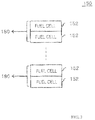
- Fig. 2 is a diagram showing a first example of the configuration of the fuel cell 150.
- the fuel cell 150 has a plurality of fuel battery cells 152. At least some of the plurality of fuel battery cells 152 are connected in series. These serially connected fuel battery cells 152 are divided into a plurality of groups.
- the voltage measurement unit 182 and the command output unit 180 are provided in each group. In other words, the voltage measurement unit 182 in each group measures a total value of the voltages of the fuel battery cells 152 of each group (value of serial voltages).
- the groups have an equal number of the fuel battery cells 152. For this reason, relay circuits to be used as the plurality of voltage measurement units 182 can all be the same.
- the magnitude (voltage) of a signal to be input to each relay circuit can be regulated by adjusting the number of the fuel battery cells 152 connected in series. Therefore, the magnitude of the input signal does not have to be designated when selecting a relay circuit to be used as the voltage measurement units 182. Therefore, a general-purpose relay circuit can be used as the voltage measurement units 182. This can reduce the manufacturing cost of the fuel cell system 10.
- the number of the fuel battery cells 152 belonging to one group needs to be set in such a manner that the total value of the output voltages of the fuel cell 150 obtained during the normal operation becomes equal to or higher than A(V) and that the total value of the output voltages of the fuel cell 150 obtained when the fuel gas is leaking becomes equal to or lower than B(V).
- the number of the fuel battery cells 152 belonging to one group needs to be set in such a manner that the total value of the voltages obtained during the normal operation becomes equal to or higher than 38.4 V and that the total value of the voltages obtained when the fuel gas is leaking becomes equal to or lower than 14.4 V.
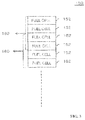
- At least one fuel battery cell 152 belongs to a plurality of groups (e.g., two groups). Such a configuration can satisfy the foregoing condition regardless of the number of the fuel battery cells 152.
- each command output unit 180 is used as each command output unit 180 in the present embodiment. This eliminates the need to execute software processing for the leakage detection processing, improving the reliability of the fuel cell system 10.
- the fuel battery cells 152 of the fuel cell 150 are divided into a plurality of groups, in which the serial voltages of each group are measured using the single voltage measurement unit 182 provided in each group. Then, when the measured value of any one of the voltage measurement units 182 becomes equal to or less than the reference value, the command output unit 180 outputs an interruption command to the interrupter 110. Therefore, while keeping the configurations of the voltage measurement units 182 and the command output units 180 simple, leakage of the fuel gas can be detected with high accuracy and the supply of the fuel gas can be interrupted.
- such a configuration can, for example, eliminate a commercially available gas detector that has generally been used, leading to a reduction of the cost of the entire system related to gas.
- the command output units 180 can detect a small amount of leakage of the gas (a slow leak).
- some of the fuel battery cells 152 are divided into a plurality of groups, so that the groups can have the same number of fuel battery cells 152 and the command output units 180 of the respective groups can be configured with the same relay circuit.
- the fuel gas remaining in the fuel cell system 10 is released to the outside of the fuel cell system 10 by a ventilation fan (not shown) that ventilates the inside of the fuel cell system 10 at all times.
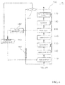
- Fig. 4 is a block diagram showing the configuration of the fuel cell system 10 according to a second embodiment.
- the fuel cell system 10 according to the present embodiment has the same configuration as the fuel cell system 10 of the first embodiment, except that when leakage of the fuel gas is detected in the casing 100, the command output unit 180 outputs an interruption command and the fan speed of the ventilation fan 190 increases.
- the present embodiment can achieve the same effects as those of the first embodiment. Also, when leakage of the fuel gas is detected in the casing 100, the fan speed of the ventilation fan 190 increases, promptly exhausting the leaked fuel gas to the outside of the casing 100.
Landscapes
- Life Sciences & Earth Sciences (AREA)
- Engineering & Computer Science (AREA)
- Manufacturing & Machinery (AREA)
- Sustainable Development (AREA)
- Sustainable Energy (AREA)
- Chemical & Material Sciences (AREA)
- Chemical Kinetics & Catalysis (AREA)
- Electrochemistry (AREA)
- General Chemical & Material Sciences (AREA)
- Fuel Cell (AREA)
Abstract
Description
- The present invention relates to a fuel cell system and a control method for the fuel cell system.
- A fuel cell is a device that converts the energy produced when generating water through a reaction between fuel gas containing hydrogen and oxygen, to produce electric energy. Because flammable gas is used as the fuel gas in the fuel cell, the system using the fuel cell needs to be designed to prevent leakage of the fuel gas.
- Patent Literature 1 discloses a technique related to leakage of fuel gas. The technique disclosed in Patent Literature 1 measures an output voltage of a fuel cell during suspension of supply of fuel gas to the fuel cell, and determines the presence/absence of leakage of the fuel gas based on the result of the measurement.
- Patent Literature 1:
Japanese Patent Application Laid-open No. 2009-146658 - In order to enhance the safety of a fuel cell, supply of fuel gas needs to be stopped when the fuel gas leaks during the generation of electricity by the fuel cell. Unfortunately, the technique disclosed in Patent Literature 1 theoretically is not capable of detecting leakage of fuel gas while the fuel cell generates electricity.
- An object of the present invention is to provide a fuel cell system that is capable of suspending the supply of fuel gas when the fuel gas leaks, even during the generation of electricity by a fuel cell, and a control method for the fuel cell system.
- A fuel cell system according to the present invention has a fuel cell, a voltage measurement unit, a comment output unit, and an interrupter. The fuel cell receives fuel gas through a pipe. The voltage measurement unit measures an output voltage of the fuel cell. The command output unit outputs an interruption command when a measurement result of the voltage measurement unit is equal to or less than a reference value during the generation of electricity by the fuel cell. The interrupter is provided in the pipe described above and interrupts the supply of the fuel gas to the fuel cell in response to the interruption command.
- The present invention can suspends the supply of fuel gas when the fuel gas leaks, even during the generation of electricity by a fuel cell.
- The foregoing and other objects, features and advantages of the present invention will become more apparent from the following description of preferred embodiments and accompanying diagrams.
-
Fig. 1 is a diagram showing a functional configuration of a fuel cell system according to a first embodiment; -
Fig. 2 is a diagram showing a first example of a configuration of a fuel cell; -
Fig. 3 is a diagram showing a second example of the configuration of the fuel cell; and -
Fig. 4 is a diagram showing a functional configuration of a fuel cell system according to a second embodiment. - Embodiments are described hereinafter with reference to the drawings. The same reference numerals are used to indicate the corresponding components in all the diagrams, and the redundant explanation thereof will be omitted accordingly.
-
Fig. 1 is a block diagram showing a functional configuration of afuel cell system 10 according to a first embodiment. Thefuel cell system 10 according to the present embodiment has afuel cell 150, avoltage measurement unit 182, acommand output unit 180, and aninterrupter 110. Thefuel cell 150 receives fuel gas through a pipe and generates electricity using the received fuel gas and oxygen-containing gas (e.g., air). Thevoltage measurement unit 182 measures an output voltage of thefuel cell 150. Thecommand output unit 180 outputs an interruption command when the measurement result of thevoltage measurement unit 182 becomes equal to or less than a reference value during the generation of electricity by thefuel cell 150. Theinterrupter 110 is provided in the pipe and interrupts the supply of fuel gas to thefuel cell 150 in response to the interruption command output by thecommand output unit 180. Theinterrupter 110 is, for example, a valve. - The
voltage measurement unit 182 outputs the output voltage of thefuel cell 150 to thecommand output unit 180 only while thefuel cell 150 generates electricity. Because outputs of thefuel cell 150 are not stable immediately after the beginning of the operation of thefuel cell 150, thevoltage measurement unit 182 starts outputting the output voltage of thefuel cell 150 after a lapse of a certain period of time (e.g., at least one minute) from the start of the operation of thefuel cell 150. Such a process can be realized by controlling the operation of thevoltage measurement unit 182 using a timer. - In the present embodiment, the
command output unit 180 is configured with an electric circuit, and does not execute software processing. Thecommand output unit 180 is configured with, for example, a relay circuit. Therefore, thecommand output unit 180 is highly reliable and complies with a CE marking. Thecommand output unit 180 outputs an interruption command when the measurement result of thevoltage measurement unit 182 becomes equal to or less than the reference value throughout a predetermined certain period of time (e.g., at least one second). Such a process can be realized by combining the relay circuit with the timer. - The
fuel cell system 10 further has adesulfurizer 120, areformer 130, atransformer 140, aburner 160, and awater recovery device 170. Thedesulfurizer 120 performs a desulfurization treatment on the fuel gas that passes through theinterrupter 110. Thereformer 130 performs a reforming treatment on the resultant desulfurized fuel gas. Theburner 160 burns the combustible components of exhaust gas supplied from thefuel cell 150. The heat generated by theburner 160 is used as a heat source of thereformer 130. Thewater recovery device 170 recovers the water contained in the exhaust gas supplied from theburner 160. - The
interrupter 110,desulfurizer 120,reformer 130,transformer 140,fuel cell 150,burner 160, andwater recovery device 170 are stored in acasing 100. Thecasing 100 is provided with aventilation fan 190 and aninlet port 192. While thefuel cell 150 is operated, the atmosphere inside thecasing 100 is exhausted by theventilation fan 190. Therefore, even when the fuel gas leaks into thecasing 100, the leaked fuel gas is exhausted promptly to the outside of thecasing 100. -
Fig. 2 is a diagram showing a first example of the configuration of thefuel cell 150. Thefuel cell 150 has a plurality offuel battery cells 152. At least some of the plurality offuel battery cells 152 are connected in series. These serially connectedfuel battery cells 152 are divided into a plurality of groups. Thevoltage measurement unit 182 and thecommand output unit 180 are provided in each group. In other words, thevoltage measurement unit 182 in each group measures a total value of the voltages of thefuel battery cells 152 of each group (value of serial voltages). In the present embodiment, the groups have an equal number of thefuel battery cells 152. For this reason, relay circuits to be used as the plurality ofvoltage measurement units 182 can all be the same. In addition, the magnitude (voltage) of a signal to be input to each relay circuit can be regulated by adjusting the number of thefuel battery cells 152 connected in series. Therefore, the magnitude of the input signal does not have to be designated when selecting a relay circuit to be used as thevoltage measurement units 182. Therefore, a general-purpose relay circuit can be used as thevoltage measurement units 182. This can reduce the manufacturing cost of thefuel cell system 10. - With the ON-state voltage of the relay circuit used as each
voltage measurement unit 182 being taken as A(V) and the OFF-state voltage of the same as B(V), the number of thefuel battery cells 152 belonging to one group needs to be set in such a manner that the total value of the output voltages of thefuel cell 150 obtained during the normal operation becomes equal to or higher than A(V) and that the total value of the output voltages of thefuel cell 150 obtained when the fuel gas is leaking becomes equal to or lower than B(V). For instance, in case of using a relay circuit with a rated voltage of 48 VDC, ON-state voltage of 38.4 V and OFF-state voltage of 14.4 V, the number of thefuel battery cells 152 belonging to one group needs to be set in such a manner that the total value of the voltages obtained during the normal operation becomes equal to or higher than 38.4 V and that the total value of the voltages obtained when the fuel gas is leaking becomes equal to or lower than 14.4 V. -
Fig. 3 is a diagram showing a second example of the configuration of thefuel cell 150. As described above, with the ON-state voltage of the relay circuit being taken as A(V) and the OFF-state voltage of the same as B(V), the number of thefuel battery cells 152 belonging to one group needs to be set in such a manner that the total value of the voltages obtained during the normal operation becomes equal to or higher than A(V) and that the total value of the voltages obtained when the fuel gas is leaking becomes equal to or lower than B(V). In case of using identical relay circuits as thevoltage measurement units 182, the number of thefuel battery cells 152 in each group needs to be the same. In this case, simply dividing the number of thefuel battery cells 152 by a factor of this number (= the number of groups) might not satisfy the condition described above. In the example shown inFig. 3 , at least onefuel battery cell 152 belongs to a plurality of groups (e.g., two groups). Such a configuration can satisfy the foregoing condition regardless of the number of thefuel battery cells 152. - The principle of detecting leakage of the fuel gas in the
fuel cell system 10 is described next. When the fuel gas leaks in thefuel cell system 10, the output voltage of thefuel cell 150 drops. Thus, in a case where the voltage of thefuel cell 150 becomes equal to or less than the reference value, it can be determined that there is leakage of the fuel gas in thefuel cell system 10. Therefore, as in the present embodiment in which thecommand output unit 180 outputs an interruption command to theinterrupter 110 when the measurement result of thevoltage measurement unit 182 becomes equal to or less than the reference value during the generation of electricity by thefuel cell 150, leakage of the fuel gas in thefuel cell system 10 can be prevented. - Furthermore, a relay circuit is used as each
command output unit 180 in the present embodiment. This eliminates the need to execute software processing for the leakage detection processing, improving the reliability of thefuel cell system 10. - Moreover, the
fuel battery cells 152 of thefuel cell 150 are divided into a plurality of groups, in which the serial voltages of each group are measured using the singlevoltage measurement unit 182 provided in each group. Then, when the measured value of any one of thevoltage measurement units 182 becomes equal to or less than the reference value, thecommand output unit 180 outputs an interruption command to theinterrupter 110. Therefore, while keeping the configurations of thevoltage measurement units 182 and thecommand output units 180 simple, leakage of the fuel gas can be detected with high accuracy and the supply of the fuel gas can be interrupted. - In addition, such a configuration can, for example, eliminate a commercially available gas detector that has generally been used, leading to a reduction of the cost of the entire system related to gas.
- In some cases, there is a voltage reduction in which the measured value of any one of the
voltage measurement units 182 does not become equal to or less than the reference value. In such a case, by understanding the correlation between the voltage values and the amount of leakage of the gas beforehand and storing the correlation in thecommand output units 180, thecommand output units 180 can detect a small amount of leakage of the gas (a slow leak). - Also, some of the
fuel battery cells 152 are divided into a plurality of groups, so that the groups can have the same number offuel battery cells 152 and thecommand output units 180 of the respective groups can be configured with the same relay circuit. - When detecting leakage of the fuel gas and interrupting the supply of the fuel gas by means of the
interrupter 110, the fuel gas remaining in thefuel cell system 10 is released to the outside of thefuel cell system 10 by a ventilation fan (not shown) that ventilates the inside of thefuel cell system 10 at all times. -
Fig. 4 is a block diagram showing the configuration of thefuel cell system 10 according to a second embodiment. Thefuel cell system 10 according to the present embodiment has the same configuration as thefuel cell system 10 of the first embodiment, except that when leakage of the fuel gas is detected in thecasing 100, thecommand output unit 180 outputs an interruption command and the fan speed of theventilation fan 190 increases. - The present embodiment can achieve the same effects as those of the first embodiment. Also, when leakage of the fuel gas is detected in the
casing 100, the fan speed of theventilation fan 190 increases, promptly exhausting the leaked fuel gas to the outside of thecasing 100. - The above has specifically described the present invention based on the embodiments; however, the present invention is not intended to be limited to the foregoing embodiments, and it goes without saying that various changes can be made without departing from the gist of the present invention.
- This application claims priority based on
Japanese Patent Application No. 2013-080171 filed on April 8, 2013
Claims (6)
- A fuel cell system, comprising:a fuel cell that receives fuel gas through a pipe;a voltage measurement unit that measures an output voltage of the fuel cell;a command output unit that outputs an interruption command when a measurement result of the voltage measurement unit is equal to or less than a reference value during the generation of electricity by the fuel cell; andan interrupter that is provided in the pipe and interrupts the supply of the fuel gas to the fuel cell in response to the interruption command.
- The fuel cell system according to claim 1, wherein the command output unit is a relay circuit.
- The fuel cell system according to claim 1 or 2, wherein
the fuel cell has a plurality of fuel battery cells,
the plurality of fuel battery cells are divided into a plurality of groups,
each of the plurality of groups is provided with the voltage measurement unit, and
the command output unit outputs the interruption command when a measurement result of at least one of the voltage measurement units is equal to or less than the reference value. - The fuel cell system according to claim 3, wherein
the plurality of groups have the same number of fuel battery cells, and
at least one of the fuel battery cells belongs to two or more of the plurality of groups. - The fuel cell system according to any one of claims 1 to 4, further comprising:a casing for storing the fuel cell; anda ventilation fan provided in the casing,wherein the ventilation fan exhausts an atmosphere inside the casing while the fuel cell is operated, andthe command output unit increases a fan speed of the ventilation fan when outputting the interruption command.
- A control method for a fuel cell system, wherein
when an output voltage of a fuel cell is equal to or less than a reference value during the generation of electricity by the fuel cell, a relay sequence outputs an interruption command to an interrupter that is attached to a pipe for supplying fuel gas to the fuel cell, and
the interrupter interrupts the supply of the fuel gas to the fuel cell in response to the interruption command.
Applications Claiming Priority (2)
| Application Number | Priority Date | Filing Date | Title |
|---|---|---|---|
| JP2013080171 | 2013-04-08 | ||
| PCT/JP2013/078563 WO2014167746A1 (en) | 2013-04-08 | 2013-10-22 | Fuel cell system and fuel cell system control method |
Publications (3)
| Publication Number | Publication Date |
|---|---|
| EP2985828A1 true EP2985828A1 (en) | 2016-02-17 |
| EP2985828A4 EP2985828A4 (en) | 2017-01-04 |
| EP2985828B1 EP2985828B1 (en) | 2018-07-18 |
Family
ID=51689170
Family Applications (1)
| Application Number | Title | Priority Date | Filing Date |
|---|---|---|---|
| EP13881894.3A Active EP2985828B1 (en) | 2013-04-08 | 2013-10-22 | Fuel cell system and fuel cell system control method |
Country Status (3)
| Country | Link |
|---|---|
| EP (1) | EP2985828B1 (en) |
| JP (1) | JP6083468B2 (en) |
| WO (1) | WO2014167746A1 (en) |
Family Cites Families (8)
| Publication number | Priority date | Publication date | Assignee | Title |
|---|---|---|---|---|
| JP2000077086A (en) * | 1998-08-31 | 2000-03-14 | Toshiba Corp | Fuel cell power plant |
| JP4381508B2 (en) * | 1999-06-22 | 2009-12-09 | パナソニック株式会社 | Fuel cell system |
| JP3872756B2 (en) * | 2000-09-27 | 2007-01-24 | シーメンス アクチエンゲゼルシヤフト | Fuel cell equipment |
| JP2004220823A (en) * | 2003-01-10 | 2004-08-05 | Toyotomi Co Ltd | Cell abnormality detection device of fuel cell |
| JP2006019115A (en) * | 2004-07-01 | 2006-01-19 | Toyota Motor Corp | Fuel cell cell voltage detection device |
| JP5109343B2 (en) * | 2006-11-15 | 2012-12-26 | トヨタ自動車株式会社 | Fuel cell and fuel cell system |
| JP2009146658A (en) | 2007-12-12 | 2009-07-02 | Toyota Motor Corp | Fuel cell system and fuel gas leak detection method |
| JP5589641B2 (en) * | 2010-07-23 | 2014-09-17 | アイシン精機株式会社 | Fuel cell system |
-
2013
- 2013-10-22 EP EP13881894.3A patent/EP2985828B1/en active Active
- 2013-10-22 WO PCT/JP2013/078563 patent/WO2014167746A1/en not_active Ceased
- 2013-10-22 JP JP2015511073A patent/JP6083468B2/en active Active
Also Published As
| Publication number | Publication date |
|---|---|
| EP2985828B1 (en) | 2018-07-18 |
| JP6083468B2 (en) | 2017-02-22 |
| EP2985828A4 (en) | 2017-01-04 |
| JPWO2014167746A1 (en) | 2017-02-16 |
| WO2014167746A1 (en) | 2014-10-16 |
Similar Documents
| Publication | Publication Date | Title |
|---|---|---|
| JP5063340B2 (en) | Fuel cell system and operation method thereof | |
| KR100827954B1 (en) | Molten carbonate fuel cell protection device and method | |
| CN101506091B (en) | Hydrogen generator, method of operating hydrogen generator, and fuel cell system | |
| RU2013125753A (en) | ENERGY GENERATION SYSTEM AND METHOD OF WORK | |
| JP5180413B2 (en) | Fuel cell system and operation method thereof | |
| US20220223892A1 (en) | Fuel cell system | |
| JP2014026873A (en) | Fuel cell power generation system and control method for the same | |
| JP5877292B2 (en) | Fuel cell system | |
| EP2985828B1 (en) | Fuel cell system and fuel cell system control method | |
| WO2015129261A1 (en) | Electricity-generation system and method for operating electricity-generation system | |
| JP5190394B2 (en) | Off-gas fired boiler system | |
| JP2011165318A (en) | Fuel cell generator system | |
| JP2011014458A (en) | Fuel cell power generation system | |
| EP2693552B1 (en) | Fuel cell system and operation method thereof | |
| JP2005129491A (en) | Fuel cell power generation system | |
| JP5607951B2 (en) | Method for maintaining a stopped state of a fuel cell system | |
| JP5795289B2 (en) | Fuel supply method and system for fuel cell | |
| JP2007265669A (en) | Leak detecting method in fuel cell power generation system | |
| DK3024077T3 (en) | Device and method for supplying a fuel cell battery | |
| JP2016152102A (en) | Gas leakage prevention device and fuel battery system having the same | |
| JP5477032B2 (en) | Fuel cell system | |
| JP6931793B2 (en) | Fuel cell system | |
| WO2012132260A1 (en) | Fuel cell system and method for operating same | |
| JP6892354B2 (en) | Power generator, control device and control program | |
| JP2025173947A (en) | fuel cell system |
Legal Events
| Date | Code | Title | Description |
|---|---|---|---|
| PUAI | Public reference made under article 153(3) epc to a published international application that has entered the european phase |
Free format text: ORIGINAL CODE: 0009012 |
|
| 17P | Request for examination filed |
Effective date: 20150902 |
|
| AK | Designated contracting states |
Kind code of ref document: A1 Designated state(s): AL AT BE BG CH CY CZ DE DK EE ES FI FR GB GR HR HU IE IS IT LI LT LU LV MC MK MT NL NO PL PT RO RS SE SI SK SM TR |
|
| AX | Request for extension of the european patent |
Extension state: BA ME |
|
| DAX | Request for extension of the european patent (deleted) | ||
| A4 | Supplementary search report drawn up and despatched |
Effective date: 20161206 |
|
| RIC1 | Information provided on ipc code assigned before grant |
Ipc: H01M 8/04 20060101AFI20161130BHEP |
|
| REG | Reference to a national code |
Ref country code: DE Ref legal event code: R079 Ref document number: 602013040662 Country of ref document: DE Free format text: PREVIOUS MAIN CLASS: H01M0008040000 Ipc: H01M0008045370 |
|
| GRAP | Despatch of communication of intention to grant a patent |
Free format text: ORIGINAL CODE: EPIDOSNIGR1 |
|
| RIC1 | Information provided on ipc code assigned before grant |
Ipc: H01M 8/04537 20160101AFI20180119BHEP Ipc: H01M 8/04746 20160101ALI20180119BHEP |
|
| INTG | Intention to grant announced |
Effective date: 20180207 |
|
| GRAS | Grant fee paid |
Free format text: ORIGINAL CODE: EPIDOSNIGR3 |
|
| GRAA | (expected) grant |
Free format text: ORIGINAL CODE: 0009210 |
|
| AK | Designated contracting states |
Kind code of ref document: B1 Designated state(s): AL AT BE BG CH CY CZ DE DK EE ES FI FR GB GR HR HU IE IS IT LI LT LU LV MC MK MT NL NO PL PT RO RS SE SI SK SM TR |
|
| REG | Reference to a national code |
Ref country code: GB Ref legal event code: FG4D |
|
| REG | Reference to a national code |
Ref country code: CH Ref legal event code: EP |
|
| REG | Reference to a national code |
Ref country code: IE Ref legal event code: FG4D |
|
| REG | Reference to a national code |
Ref country code: AT Ref legal event code: REF Ref document number: 1020328 Country of ref document: AT Kind code of ref document: T Effective date: 20180815 |
|
| REG | Reference to a national code |
Ref country code: DE Ref legal event code: R096 Ref document number: 602013040662 Country of ref document: DE |
|
| REG | Reference to a national code |
Ref country code: FR Ref legal event code: PLFP Year of fee payment: 6 |
|
| REG | Reference to a national code |
Ref country code: NL Ref legal event code: MP Effective date: 20180718 |
|
| REG | Reference to a national code |
Ref country code: LT Ref legal event code: MG4D |
|
| REG | Reference to a national code |
Ref country code: AT Ref legal event code: MK05 Ref document number: 1020328 Country of ref document: AT Kind code of ref document: T Effective date: 20180718 |
|
| PG25 | Lapsed in a contracting state [announced via postgrant information from national office to epo] |
Ref country code: NL Free format text: LAPSE BECAUSE OF FAILURE TO SUBMIT A TRANSLATION OF THE DESCRIPTION OR TO PAY THE FEE WITHIN THE PRESCRIBED TIME-LIMIT Effective date: 20180718 |
|
| PG25 | Lapsed in a contracting state [announced via postgrant information from national office to epo] |
Ref country code: BG Free format text: LAPSE BECAUSE OF FAILURE TO SUBMIT A TRANSLATION OF THE DESCRIPTION OR TO PAY THE FEE WITHIN THE PRESCRIBED TIME-LIMIT Effective date: 20181018 Ref country code: LT Free format text: LAPSE BECAUSE OF FAILURE TO SUBMIT A TRANSLATION OF THE DESCRIPTION OR TO PAY THE FEE WITHIN THE PRESCRIBED TIME-LIMIT Effective date: 20180718 Ref country code: RS Free format text: LAPSE BECAUSE OF FAILURE TO SUBMIT A TRANSLATION OF THE DESCRIPTION OR TO PAY THE FEE WITHIN THE PRESCRIBED TIME-LIMIT Effective date: 20180718 Ref country code: PL Free format text: LAPSE BECAUSE OF FAILURE TO SUBMIT A TRANSLATION OF THE DESCRIPTION OR TO PAY THE FEE WITHIN THE PRESCRIBED TIME-LIMIT Effective date: 20180718 Ref country code: IS Free format text: LAPSE BECAUSE OF FAILURE TO SUBMIT A TRANSLATION OF THE DESCRIPTION OR TO PAY THE FEE WITHIN THE PRESCRIBED TIME-LIMIT Effective date: 20181118 Ref country code: AT Free format text: LAPSE BECAUSE OF FAILURE TO SUBMIT A TRANSLATION OF THE DESCRIPTION OR TO PAY THE FEE WITHIN THE PRESCRIBED TIME-LIMIT Effective date: 20180718 Ref country code: NO Free format text: LAPSE BECAUSE OF FAILURE TO SUBMIT A TRANSLATION OF THE DESCRIPTION OR TO PAY THE FEE WITHIN THE PRESCRIBED TIME-LIMIT Effective date: 20181018 Ref country code: SE Free format text: LAPSE BECAUSE OF FAILURE TO SUBMIT A TRANSLATION OF THE DESCRIPTION OR TO PAY THE FEE WITHIN THE PRESCRIBED TIME-LIMIT Effective date: 20180718 Ref country code: GR Free format text: LAPSE BECAUSE OF FAILURE TO SUBMIT A TRANSLATION OF THE DESCRIPTION OR TO PAY THE FEE WITHIN THE PRESCRIBED TIME-LIMIT Effective date: 20181019 Ref country code: FI Free format text: LAPSE BECAUSE OF FAILURE TO SUBMIT A TRANSLATION OF THE DESCRIPTION OR TO PAY THE FEE WITHIN THE PRESCRIBED TIME-LIMIT Effective date: 20180718 |
|
| PG25 | Lapsed in a contracting state [announced via postgrant information from national office to epo] |
Ref country code: HR Free format text: LAPSE BECAUSE OF FAILURE TO SUBMIT A TRANSLATION OF THE DESCRIPTION OR TO PAY THE FEE WITHIN THE PRESCRIBED TIME-LIMIT Effective date: 20180718 Ref country code: LV Free format text: LAPSE BECAUSE OF FAILURE TO SUBMIT A TRANSLATION OF THE DESCRIPTION OR TO PAY THE FEE WITHIN THE PRESCRIBED TIME-LIMIT Effective date: 20180718 Ref country code: AL Free format text: LAPSE BECAUSE OF FAILURE TO SUBMIT A TRANSLATION OF THE DESCRIPTION OR TO PAY THE FEE WITHIN THE PRESCRIBED TIME-LIMIT Effective date: 20180718 |
|
| REG | Reference to a national code |
Ref country code: DE Ref legal event code: R097 Ref document number: 602013040662 Country of ref document: DE |
|
| PG25 | Lapsed in a contracting state [announced via postgrant information from national office to epo] |
Ref country code: EE Free format text: LAPSE BECAUSE OF FAILURE TO SUBMIT A TRANSLATION OF THE DESCRIPTION OR TO PAY THE FEE WITHIN THE PRESCRIBED TIME-LIMIT Effective date: 20180718 Ref country code: CZ Free format text: LAPSE BECAUSE OF FAILURE TO SUBMIT A TRANSLATION OF THE DESCRIPTION OR TO PAY THE FEE WITHIN THE PRESCRIBED TIME-LIMIT Effective date: 20180718 Ref country code: IT Free format text: LAPSE BECAUSE OF FAILURE TO SUBMIT A TRANSLATION OF THE DESCRIPTION OR TO PAY THE FEE WITHIN THE PRESCRIBED TIME-LIMIT Effective date: 20180718 Ref country code: RO Free format text: LAPSE BECAUSE OF FAILURE TO SUBMIT A TRANSLATION OF THE DESCRIPTION OR TO PAY THE FEE WITHIN THE PRESCRIBED TIME-LIMIT Effective date: 20180718 Ref country code: ES Free format text: LAPSE BECAUSE OF FAILURE TO SUBMIT A TRANSLATION OF THE DESCRIPTION OR TO PAY THE FEE WITHIN THE PRESCRIBED TIME-LIMIT Effective date: 20180718 |
|
| PLBE | No opposition filed within time limit |
Free format text: ORIGINAL CODE: 0009261 |
|
| STAA | Information on the status of an ep patent application or granted ep patent |
Free format text: STATUS: NO OPPOSITION FILED WITHIN TIME LIMIT |
|
| PG25 | Lapsed in a contracting state [announced via postgrant information from national office to epo] |
Ref country code: SK Free format text: LAPSE BECAUSE OF FAILURE TO SUBMIT A TRANSLATION OF THE DESCRIPTION OR TO PAY THE FEE WITHIN THE PRESCRIBED TIME-LIMIT Effective date: 20180718 Ref country code: SM Free format text: LAPSE BECAUSE OF FAILURE TO SUBMIT A TRANSLATION OF THE DESCRIPTION OR TO PAY THE FEE WITHIN THE PRESCRIBED TIME-LIMIT Effective date: 20180718 Ref country code: DK Free format text: LAPSE BECAUSE OF FAILURE TO SUBMIT A TRANSLATION OF THE DESCRIPTION OR TO PAY THE FEE WITHIN THE PRESCRIBED TIME-LIMIT Effective date: 20180718 |
|
| REG | Reference to a national code |
Ref country code: CH Ref legal event code: PL |
|
| 26N | No opposition filed |
Effective date: 20190423 |
|
| GBPC | Gb: european patent ceased through non-payment of renewal fee |
Effective date: 20181022 |
|
| REG | Reference to a national code |
Ref country code: BE Ref legal event code: MM Effective date: 20181031 |
|
| PG25 | Lapsed in a contracting state [announced via postgrant information from national office to epo] |
Ref country code: LU Free format text: LAPSE BECAUSE OF NON-PAYMENT OF DUE FEES Effective date: 20181022 Ref country code: MC Free format text: LAPSE BECAUSE OF FAILURE TO SUBMIT A TRANSLATION OF THE DESCRIPTION OR TO PAY THE FEE WITHIN THE PRESCRIBED TIME-LIMIT Effective date: 20180718 |
|
| REG | Reference to a national code |
Ref country code: IE Ref legal event code: MM4A |
|
| PG25 | Lapsed in a contracting state [announced via postgrant information from national office to epo] |
Ref country code: BE Free format text: LAPSE BECAUSE OF NON-PAYMENT OF DUE FEES Effective date: 20181031 Ref country code: CH Free format text: LAPSE BECAUSE OF NON-PAYMENT OF DUE FEES Effective date: 20181031 Ref country code: LI Free format text: LAPSE BECAUSE OF NON-PAYMENT OF DUE FEES Effective date: 20181031 Ref country code: SI Free format text: LAPSE BECAUSE OF FAILURE TO SUBMIT A TRANSLATION OF THE DESCRIPTION OR TO PAY THE FEE WITHIN THE PRESCRIBED TIME-LIMIT Effective date: 20180718 |
|
| PG25 | Lapsed in a contracting state [announced via postgrant information from national office to epo] |
Ref country code: IE Free format text: LAPSE BECAUSE OF NON-PAYMENT OF DUE FEES Effective date: 20181022 Ref country code: GB Free format text: LAPSE BECAUSE OF NON-PAYMENT OF DUE FEES Effective date: 20181022 |
|
| PG25 | Lapsed in a contracting state [announced via postgrant information from national office to epo] |
Ref country code: MT Free format text: LAPSE BECAUSE OF NON-PAYMENT OF DUE FEES Effective date: 20181022 |
|
| PG25 | Lapsed in a contracting state [announced via postgrant information from national office to epo] |
Ref country code: TR Free format text: LAPSE BECAUSE OF FAILURE TO SUBMIT A TRANSLATION OF THE DESCRIPTION OR TO PAY THE FEE WITHIN THE PRESCRIBED TIME-LIMIT Effective date: 20180718 |
|
| PG25 | Lapsed in a contracting state [announced via postgrant information from national office to epo] |
Ref country code: PT Free format text: LAPSE BECAUSE OF FAILURE TO SUBMIT A TRANSLATION OF THE DESCRIPTION OR TO PAY THE FEE WITHIN THE PRESCRIBED TIME-LIMIT Effective date: 20180718 |
|
| PG25 | Lapsed in a contracting state [announced via postgrant information from national office to epo] |
Ref country code: CY Free format text: LAPSE BECAUSE OF FAILURE TO SUBMIT A TRANSLATION OF THE DESCRIPTION OR TO PAY THE FEE WITHIN THE PRESCRIBED TIME-LIMIT Effective date: 20180718 Ref country code: HU Free format text: LAPSE BECAUSE OF FAILURE TO SUBMIT A TRANSLATION OF THE DESCRIPTION OR TO PAY THE FEE WITHIN THE PRESCRIBED TIME-LIMIT; INVALID AB INITIO Effective date: 20131022 Ref country code: MK Free format text: LAPSE BECAUSE OF NON-PAYMENT OF DUE FEES Effective date: 20180718 |
|
| PGFP | Annual fee paid to national office [announced via postgrant information from national office to epo] |
Ref country code: FR Payment date: 20250908 Year of fee payment: 13 |
|
| PGFP | Annual fee paid to national office [announced via postgrant information from national office to epo] |
Ref country code: DE Payment date: 20250902 Year of fee payment: 13 |