EP2985752A1 - Signboard device - Google Patents
Signboard device Download PDFInfo
- Publication number
- EP2985752A1 EP2985752A1 EP14782420.5A EP14782420A EP2985752A1 EP 2985752 A1 EP2985752 A1 EP 2985752A1 EP 14782420 A EP14782420 A EP 14782420A EP 2985752 A1 EP2985752 A1 EP 2985752A1
- Authority
- EP
- European Patent Office
- Prior art keywords
- light
- dynamic
- source
- image block
- length
- Prior art date
- Legal status (The legal status is an assumption and is not a legal conclusion. Google has not performed a legal analysis and makes no representation as to the accuracy of the status listed.)
- Withdrawn
Links
Images


Classifications
-
- G—PHYSICS
- G09—EDUCATION; CRYPTOGRAPHY; DISPLAY; ADVERTISING; SEALS
- G09F—DISPLAYING; ADVERTISING; SIGNS; LABELS OR NAME-PLATES; SEALS
- G09F13/00—Illuminated signs; Luminous advertising
- G09F13/04—Signs, boards or panels, illuminated from behind the insignia
-
- G—PHYSICS
- G09—EDUCATION; CRYPTOGRAPHY; DISPLAY; ADVERTISING; SEALS
- G09F—DISPLAYING; ADVERTISING; SIGNS; LABELS OR NAME-PLATES; SEALS
- G09F19/00—Advertising or display means not otherwise provided for
- G09F19/02—Advertising or display means not otherwise provided for incorporating moving display members
- G09F19/08—Dolls, faces, or other representations of living forms with moving parts
-
- G—PHYSICS
- G09—EDUCATION; CRYPTOGRAPHY; DISPLAY; ADVERTISING; SEALS
- G09F—DISPLAYING; ADVERTISING; SIGNS; LABELS OR NAME-PLATES; SEALS
- G09F9/00—Indicating arrangements for variable information in which the information is built-up on a support by selection or combination of individual elements
- G09F9/30—Indicating arrangements for variable information in which the information is built-up on a support by selection or combination of individual elements in which the desired character or characters are formed by combining individual elements
- G09F9/302—Indicating arrangements for variable information in which the information is built-up on a support by selection or combination of individual elements in which the desired character or characters are formed by combining individual elements characterised by the form or geometrical disposition of the individual elements
- G09F9/3026—Video wall, i.e. stackable semiconductor matrix display modules
-
- G—PHYSICS
- G09—EDUCATION; CRYPTOGRAPHY; DISPLAY; ADVERTISING; SEALS
- G09F—DISPLAYING; ADVERTISING; SIGNS; LABELS OR NAME-PLATES; SEALS
- G09F9/00—Indicating arrangements for variable information in which the information is built-up on a support by selection or combination of individual elements
- G09F9/30—Indicating arrangements for variable information in which the information is built-up on a support by selection or combination of individual elements in which the desired character or characters are formed by combining individual elements
- G09F9/35—Indicating arrangements for variable information in which the information is built-up on a support by selection or combination of individual elements in which the desired character or characters are formed by combining individual elements being liquid crystals
-
- G—PHYSICS
- G09—EDUCATION; CRYPTOGRAPHY; DISPLAY; ADVERTISING; SEALS
- G09F—DISPLAYING; ADVERTISING; SIGNS; LABELS OR NAME-PLATES; SEALS
- G09F19/00—Advertising or display means not otherwise provided for
- G09F19/02—Advertising or display means not otherwise provided for incorporating moving display members
- G09F19/08—Dolls, faces, or other representations of living forms with moving parts
- G09F2019/081—Fish
Definitions
- This invention relates to a signboard device, in particular, the invention relates to a signboard device configured by combining a plurality of blocks.
- JP-A 2012-168235 discloses the signboard device which increases attraction to an advertisement with an eyecatch effect.
- the disclosed signboard device has a dynamic-image portion inside the advertisement.
- the signboard device disclosed in JP-A 2012-168235 comprises an LCD (Liquid Crystal Display) and the light guiding member covering the entire front surface of the LCD. The light guiding member removes the shadow of a frame of the LCD so that the dynamic-image portion and the other portion are seen in an integrated manner.
- LCD Liquid Crystal Display
- JP-A 2010-113163 proposes a backlight device which comprises a plurality of light source blocks.
- a support member supporting the LCD is needed.
- the shadow of the support member may fall on the front surface of the signboard device.
- a large support member is needed.
- the large shadow may fall on the front surface of the signboard device.
- the purpose of the present invention is to provide a signboard device which can solve the problem of the shadow and deal with any size of the signboard device.
- the light-source block comprises the light source emitting light forward.
- the dynamic-image block comprises a display device and a light-emitting portion.
- the display device comprises a display portion and a housing holding the display portion.
- the display portion displays a dynamic image.
- the housing has a frame covering the periphery of the display portion when seen along a front-rear direction.
- the light-emitting portion comprises a light source for the light emitting-portion and a light-guiding member guiding the light of the light source for the light-emitting portion.
- the light-guiding member guides the light of the light source for the light-emitting portion to a front surface of the light-guiding member.
- the front surface of the light-guiding member is positioned so as to cover at least a front surface of the frame.
- the dynamic-image block and the light-source blocks are combined on a surface perpendicular to the front-rear direction.
- the length from the top end to the bottom end of each of the light-source bocks is the same as or n times or 1/n times (n being an integer) the length from the top end to the bottom end of the dynamic-image block, and the length from the left end to the right end of each of the light-source bocks is the same as or m times or 1/m times (m being an integer) the length from the left end to the right end of the dynamic-image block.
- the signboard device of the present invention is configured by combining the dynamic-image block and the light-source blocks. Therefore, the position of the dynamic-image block can be changed easily.
- the dynamic-image block is supported by the light-source blocks so that no support member supporting the dynamic-image block is needed. Therefore, the shadow of the support member doesn't fall on the front surface of the signboard.
- the light-guiding member is provided on the front surface of the frame of the LCD included in the dynamic-image block so that the shadow of the frame doesn't fall on a printed copy.
- the signboard device of the present invention is configured by combining the dynamic-image block and the light-source blocks so that the shape of the signboard can be changed easily.
- a signboard device 1 As shown in Fig. 1 and Fig. 2 , a signboard device 1 according to the embodiment of the present invention comprises a printed copy 2, a rear member 3 and a signboard housing 4. As understood from Fig. 2 , the printed copy 2 is glued on the rear member 3. The rear member 3 with on which the printed copy 2 is glued is held by the signboard housing 4. The signboard housing 4 of the present invention is used for the prior signboard device.
- the printed copy 2 is a sheet with an advertisement printed on it.
- the sheet is made of resin. A material or the thickness of the sheet may be changed as required. In the present embodiment, resin of PET (Polyethylene terephthalate) is used. Thus, the printed copy 2 can be recycled.
- the printed copy 2 of the present invention has transparent areas 2a and 2b indicated with a dotted line in Fig. 2 .
- the transparent areas 2a and 2b are the areas, which are transparent and printed with no image.
- the rear member 3 is a combined member by laying a plurality of light-source blocks 100 and dynamic-image blocks 200 in an up-down direction and a right-left direction (i.e., on a surface perpendicular to a front-rear direction of the signboard device).
- the rear member 3 has fourteen light-source blocks 100 and two dynamic-image blocks 200 arranged in 4 x 4 matrix form.
- the light-source blocks 100 and the dynamic-image blocks 200 are combined so that a shape of the rear-member 3 is rectangle when seen along the front-rear direction. Therefore, the outer shape of the signboard device 1 appears to be rectangle.
- the number of the lines and the number of the rows is equal (4 lines and 4 rows), however, the rear-member 3 has the number of the lines and the number of the rows may be different.
- the light-source block 100 comprises a plurality of light sources 130 and a housing 120 which has a box-like shape whose front opens forward.
- the light sources 130 are provided on the innermost surface 122 which corresponds to the bottom of the housing 120 in the front-rear direction.
- the light-source block 100 is made of resin whose color is white or milky so that the light is further defused by the reflection effect of white.
- the frontend portion i.e. an end portion of an opening
- the tapered portion 126 is inclined inward of the housing 120.
- the outer side edge of the housing 120 is positioned forward than the inner side edged of the housing 120.
- the light of the light source 130 is further defused as compared to using a housing provided with no tapered portion 126.
- the brightness of the light can be uniformed.
- the light-source 130 of the embodiment is LED (Light Emitting Diode), however, the light-source 130 is not limited thereto.
- the dynamic-image block 200 comprises the an LCD (Liquid Crystal Display: a display device) 210, a light-emitting portion 220 and the housing 230.
- the light-emitting portion 220, the LCD 210 and the housing 230 are arranged in this order from front in the dynamic-image block 200.
- the LCD 210 of the embodiment is not specific but typical.
- the LCD 210 has a LCP (liquid crystal panel: a display portion) 216 and a housing 212 holding the LCP 216.
- LCP liquid crystal panel
- a member constituted with a polarizing filter, a color filter and a liquid crystal layer as main components is called as "LCP”.
- a member constituted with the LCP, a driving circuit, a backlight and a light guiding member as main components is called as "LCM (Liquid Crystal Module)”.
- a combination of the LCM and the housing protecting thereof is called as "LCD”.
- the housing 212 has a front frame 214 covering the periphery of the LCP 216 when seen from the front-rear direction of the signboard device 1.
- the commercial LCD 210 (whose display size is standardized) is used so that the cost can be decreased (comparing to a case requiring to a manufacturing a specific size of the LCD).
- the present invention doesn't prevent from using the specific size of the LCD.
- the light-emitting portion 220 has an L shape in cross section on a surface defined by the front-rear direction and the up-down direction.
- the light-emitting portion 220 comprises a light source 222 for the light-emitting portion 220 and a light-guiding member 250 guiding light of the light source 222 for the light-emitting portion 220.
- the light-guiding member 250 comprises a cover potion 252 and a side portion 254.
- the cover portion 252 covers the front surface 214a of the frame 214 of the LCD 210.
- the side portion 254 extends rearward from the cover portion 252 so as to cover the side surface 214b of the frame 214.
- the front surface 256 of the light-guiding member 250 covers the front surface 214a of the frame 214 entirely. In other words, the front surface 214a of the LCD 210 does not visible when the light-emitting portion 220 is attached.
- the light source 222 for the light-emitting portion 220 of the present embodiment is provided on the side portion 254 of the light-guiding member 250. A direction or an incident angle of the light source 222 for the light-emitting portion 220 can be changed as required.
- the light sources 222 for the light-emitting portion 220 are embedded in the side portion 254 of the light-guiding member 250.
- the light sources 222 may be separated from the light-guiding member 250.
- the light sources 222 of the light-emitting member 220 of the present embodiment are also LED, however, they are not limited thereto.
- the light of the light source 222 for the light-emitting portion 220 is emitted from the front surface 256 through the light-guiding member 250.
- the light-guiding member 250 guides the light of the light source 222 to the front surface 256.
- the light-guiding member 250 has the L like shape in cross section, however the cross sectional shape of the light-guiding member 250 is not limited thereto. Any shape can be applied as long as the light of the light source 222 for the light-emitting portion 220 can be guided to the front surface 256.
- the shape of the light-guiding member 250 or the position or the direction of the light source 222 for the light-emitting 220 can be changed as required.
- the housing 230 can be made from the housing 120 used to the above-mentioned light-source block 100.
- the housing 230 is made by cutting the housing 120 on the surface perpendicular to the front-rear direction (i.e. by minimizing the depth of the housing 120) so that a material cost can be reduced.
- the housing 230 has an inner surface 232 which has no light sources 130.
- the front end 236 is a section made by cutting the housing 120 of the light-source block 100.
- the housing 212 is fixed with the LCD 210 so that the front end 236 is brought into contact with the housing 212 of the LCD 210. Therefore, the light-emitting portion 220, the LCD 210 and the housing 212 are integrated with each other.
- the size of the light-source block 100 and the size of the dynamic-image block 200 are same when seen along the front-rear direction.
- the length from the top end to the bottom end of the light-source bock 100 is the same as the length from the top end to the bottom end of the dynamic-image block
- the length from the left end to the right end of each of the light-source bocks is the same as the length from the left end to the right end of the dynamic-image block.
- the outer shape of the signboard device 1 (the rear member 3) has a rectangular shape when seen along the front-rear direction.
- the LCD 210 of the dynamic-image block is a 10.4-inch display.
- the LCD 210 is typically and commercially sold and is not made for specific use.
- the LCD 210 prescribes the size (i.e. the length from the top end to the bottom end and the length from the left end to the right end) of the dynamic-image block 200, and the size of the light-source block 100.
- the size of the light-source bocks is 1/4 times the size of the dynamic-image block. In this case, the size of the combination of the four 1/4 sized light-source blocks 100 can be the same as the size of the dynamic-image block 200.
- the position adjustment of the dynamic-image block 200 can be made in detail when the size of the light-source block 100 is minimizes than the size of the dynamic-image block 200.
- the size of the light-source bocks is 4 times the size of the dynamic-image block.
- the one light-source block 100 can cover 4 times area.
- the aspect ratio may be difference.
- the longitudinal length of the light-source block 100 is 2 times the longitudinal length of the dynamic-image block 200 and a lateral length of the length of the light-source block 100 is 4 times the lateral length of the dynamic-image block 200.
- the length from the top end to the bottom end of each of the light-source bocks may be n times or 1/n times (n being an integer) the length from the top end to the bottom end of the dynamic-image block and the length from the left end to the right end of each of the light-source bocks may be m times or 1/m times (m being an integer) the length from the left end to the right end of the dynamic-image block as long as the signboard device 1 (the rear member 3) has the rectangular outer shape when seen along the front-rear direction.
- the size of the light-source block 100 and the size of the dynamic-image block are same.
- the printed copy 2 is glued to the rear member 3 with glue 5.
- the glue 5 are put on the tapered portion 126 of the light-source blocks 100 and the front surface 256 of the dynamic-image block 200.
- the printed copy 2 and the rear member 3 are glued with each other by pushing the printed copy 2 to the rear member 3.
- there is the glue 5 between the printed copy 2 and the rear member 3 so that the printed copy 2 is not directly brought into contact with the rear member 3.
- the shadows of the tapered portion 126 of the light-source block 100 and the front surface 256 of the dynamic-image block 200 do not fall on the printed copy 2.
- the front of the dynamic-image block 200 (the front surface 256 of the light-guiding body 250) and the front of the plurality of the light-source blocks 100 (the front end of the tapered portion 126) are same in position in the front-rear direction.
- the printed copy 2 can be glued so as to make flat.
- the printed copy 2 has the transparent areas 2a corresponding to the dynamic-image block 200a and the transparent areas 2b corresponding to the dynamic-image block 200b when seen from the front.
- "moving eyes” (the dynamic-image block 200a) and “changing sentence character (the dynamic-image block 200b) of a crab can be seen through the transparent area 200a and the transparent area 200b, respectively.
- “the crab having the moving eyes”, “the moving character” and the still-picture an illustration, words or the like illustrated on the printed copy 2 are seen in integral manner.
- the frame 214 (housing 212) of the LCD 210 is generally made of the resin or the like.
- the frame 214 does not emit the light. If the light-emitting portion 220 were not used, the shadow of the frame 214 would fall on the printed copy 2. However, according to the present invention, (the front surface 256 of) the light-guiding member 250 covers the front surface 214a of the frame 214 so that the shadow of the frame 214 does not fall on the printed copy 2.
- the light-source blocks 100 and the dynamic-image blocks 200 may be coupled and fixed with each other by coupling means 300 shown in Fig. 7 .
- the coupling means 300 comprises a protrusive portion 302 and a recessed portion 304.
- the coupling means are provided on four side surfaces positions of each of the blocks 100' so that the blocks 100' are coupled in the up-down and right-left direction. With this structure, the blocks 100' are fixed in the up-down and right-left direction (a Z-direction and an X-direction).
- coupling means 300 extends forward from the rear end of the block 100' and does not communicate with the front end.
- the block 100' can not pulled rearward.
- the only one of the block 100' required to be removed can be pulled rearward when the block 100' is needed to be moved.
- Other blocks 100' do not fall down because the blocks 100' are coupled and fixed by the coupling means 300.
- a fixing member 400 shown in Fig. 8 may be provided between the blocks 100' in case some blocks 100' slip forward unintentionally.
- the fixing member 400 has a cramp-like shape having an upper engagement portion 402 and the lower engagement portion 404. Each of the upper engage portion 402 and the lower engage portion 404 has "a claw" protruding outward. As understood from Fig. 8 , the fixing member 400 is inserted through the opening formed on the inner surface 122' of the block 100'. Each of the upper engagement portion 402 and the lower engagement portion 404 engages with the block 100' so that the block 100' can not be pulled forward.
- the fixing member 400 can be released by a jig 410 having a T-like shape as illustrated in Fig. 8 .
- the jig 400 has a handle 412 corresponding the vertical line in T shape and a releasing portion 414 corresponding a horizontal line in T shape.
- Pushing portions 416 are provided both ends of the releasing portion 414 protruding therefrom. As understood from Fig. 8 , the pushing portions 416 of the jig 410 can push the upper engagement portion 402 and the lower engagement portion 404.
- the pushed upper engagement portion 402 and the pushed lower engagement portion 404 are deformed inward.
- the size of the opening provided on the inner surface 122' of the block 100' is larger than the size of the upper engagement portion 402 and the lower engagement portion 404, both included with the claws, in the up-down direction. Therefore, the pushed upper engagement portion 402 and lower engagement portion 404 can be moved rearward and removed. In this state, when pulling the block 100' forward, the block 100' can be pulled out.
- the rear member 3 illustrated in Fig. 2 has the rectangular shape. However, depending on a shape of the printed copy 2 (i.e. a shape of the signboard device), the rear member may have another shape such as, for example, shown in Fig. 9 .
- the printed copy 2' shown in Fig. 9 has a shape whose parts of upper right and upper left are removed. Accordingly, the uppermost of the right end and the left end of the light source blocks 100 are removed.
- the rear member 3 shown in Fig. 2 may be attached with one or more of the light-source block 100.
- the rear member 3 has a rectangular shape having a convex portion.
- the rear member 3 may have both the convex portion and the recessed portion depending on the shape of the printed copy or the location (a shape of a attaching space or the like) of the signboard device.
- the light-source blocks and the dynamic-image blocks can be combined freely. Therefore, the printed copy whose shape is not rectangular can be applied.
Landscapes
- Engineering & Computer Science (AREA)
- Physics & Mathematics (AREA)
- General Physics & Mathematics (AREA)
- Theoretical Computer Science (AREA)
- Chemical & Material Sciences (AREA)
- Crystallography & Structural Chemistry (AREA)
- Business, Economics & Management (AREA)
- Accounting & Taxation (AREA)
- Marketing (AREA)
- Multimedia (AREA)
- Illuminated Signs And Luminous Advertising (AREA)
- Devices For Indicating Variable Information By Combining Individual Elements (AREA)
Abstract
Description
- This invention relates to a signboard device, in particular, the invention relates to a signboard device configured by combining a plurality of blocks.
-
JP-A 2012-168235 JP-A 2012-168235 -
JP-A 2010-113163 -
- [Patent Literature 1]
JP-A 2012-168235 - [Patent Literature 2]
JP-A 2010-113163 - When arranging the LCD of
JP-A 2012-168235 - The purpose of the present invention is to provide a signboard device which can solve the problem of the shadow and deal with any size of the signboard device.
- One aspect of the present invention provides a signboard device comprising a plurality of light-source blocks and a dynamic-image block. The light-source block comprises the light source emitting light forward. The dynamic-image block comprises a display device and a light-emitting portion. The display device comprises a display portion and a housing holding the display portion. The display portion displays a dynamic image. The housing has a frame covering the periphery of the display portion when seen along a front-rear direction. The light-emitting portion comprises a light source for the light emitting-portion and a light-guiding member guiding the light of the light source for the light-emitting portion. The light-guiding member guides the light of the light source for the light-emitting portion to a front surface of the light-guiding member. The front surface of the light-guiding member is positioned so as to cover at least a front surface of the frame. The dynamic-image block and the light-source blocks are combined on a surface perpendicular to the front-rear direction. When seen along a front-rear direction, the length from the top end to the bottom end of each of the light-source bocks is the same as or n times or 1/n times (n being an integer) the length from the top end to the bottom end of the dynamic-image block, and the length from the left end to the right end of each of the light-source bocks is the same as or m times or 1/m times (m being an integer) the length from the left end to the right end of the dynamic-image block.
- Similarly to a block wall, the signboard device of the present invention is configured by combining the dynamic-image block and the light-source blocks. Therefore, the position of the dynamic-image block can be changed easily. The dynamic-image block is supported by the light-source blocks so that no support member supporting the dynamic-image block is needed. Therefore, the shadow of the support member doesn't fall on the front surface of the signboard. The light-guiding member is provided on the front surface of the frame of the LCD included in the dynamic-image block so that the shadow of the frame doesn't fall on a printed copy. Thus, the dynamic-image portion and the other portion are seen in more integrated manner. The signboard device of the present invention is configured by combining the dynamic-image block and the light-source blocks so that the shape of the signboard can be changed easily.
-
-
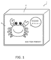
Fig.1 is a view showing a signboard device according to an embodiment of the present invention. -
Fig. 2 is exploded oblique view showing the signboard device ofFig. 1 . -
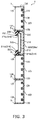
Fig. 3 is a cross-sectional view of a rear member, taken along lines III-III. -
Fig. 4 is a view showing a light-source block used in the signboard device ofFig. 1 . -
Fig. 5 is a view showing a dynamic-image block included in the signboard device ofFig. 1 . -
Fig. 6 is an exploded view of the dynamic-image block ofFig. 5 . The light-emitting portion is shown in an oblique cross-sectional view to facilitate the understanding of the shape. -
Fig. 7 is a schematic view showing a coupling member of the dynamic-image block and the light-source block. -
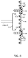
Fig. 8 is a view showing the dynamic-image block and the light-source block the coupling of which is fixed by the fixing member and showing a jig which releases the fixing by the fixing member. -
Fig. 9 is an exploded view showing a variation example of the signboard device ofFig. 2 . - As shown in
Fig. 1 andFig. 2 , a signboard device 1 according to the embodiment of the present invention comprises a printedcopy 2, arear member 3 and asignboard housing 4. As understood fromFig. 2 , the printedcopy 2 is glued on therear member 3. Therear member 3 with on which the printedcopy 2 is glued is held by thesignboard housing 4. Thesignboard housing 4 of the present invention is used for the prior signboard device. - The printed
copy 2 is a sheet with an advertisement printed on it. The sheet is made of resin. A material or the thickness of the sheet may be changed as required. In the present embodiment, resin of PET (Polyethylene terephthalate) is used. Thus, the printedcopy 2 can be recycled. The printedcopy 2 of the present invention hastransparent areas Fig. 2 . Thetransparent areas - As shown in
Fig. 2 , therear member 3 is a combined member by laying a plurality of light-source blocks 100 and dynamic-image blocks 200 in an up-down direction and a right-left direction (i.e., on a surface perpendicular to a front-rear direction of the signboard device). In the present embodiment, therear member 3 has fourteen light-source blocks 100 and two dynamic-image blocks 200 arranged in 4 x 4 matrix form. The light-source blocks 100 and the dynamic-image blocks 200 are combined so that a shape of the rear-member 3 is rectangle when seen along the front-rear direction. Therefore, the outer shape of the signboard device 1 appears to be rectangle. The number of the lines and the number of the rows is equal (4 lines and 4 rows), however, the rear-member 3 has the number of the lines and the number of the rows may be different. - As shown in
Fig. 3 andFig. 4 , the light-source block 100 comprises a plurality oflight sources 130 and ahousing 120 which has a box-like shape whose front opens forward. Thelight sources 130 are provided on theinnermost surface 122 which corresponds to the bottom of thehousing 120 in the front-rear direction. The light-source block 100 is made of resin whose color is white or milky so that the light is further defused by the reflection effect of white. As understood fromFig. 3 , the frontend portion (i.e. an end portion of an opening) is formed with a taperedportion 126. The taperedportion 126 is inclined inward of thehousing 120. In other words, on the taperedportion 126, the outer side edge of thehousing 120 is positioned forward than the inner side edged of thehousing 120. With this structure, the light of thelight source 130 is further defused as compared to using a housing provided with notapered portion 126. The brightness of the light can be uniformed. The light-source 130 of the embodiment is LED (Light Emitting Diode), however, the light-source 130 is not limited thereto. - As shown in
Fig. 3 ,Fig. 5 andFig. 6 , the dynamic-image block 200 comprises the an LCD (Liquid Crystal Display: a display device) 210, a light-emittingportion 220 and thehousing 230. As understood fromFig. 6 , the light-emittingportion 220, theLCD 210 and thehousing 230 are arranged in this order from front in the dynamic-image block 200. - The
LCD 210 of the embodiment is not specific but typical. In other words, as shown inFig. 3 andFig. 6 , theLCD 210 has a LCP (liquid crystal panel: a display portion) 216 and ahousing 212 holding theLCP 216. In this embodiment, a member constituted with a polarizing filter, a color filter and a liquid crystal layer as main components is called as "LCP". A member constituted with the LCP, a driving circuit, a backlight and a light guiding member as main components is called as "LCM (Liquid Crystal Module)". A combination of the LCM and the housing protecting thereof is called as "LCD". To facilitate the explanation the "LCP 216, "housing 212 (frame 214)" and "LCD 210" are specifically illustrated in the present drawings and the illustration and the explanation of other configuration are omitted. Thehousing 212 has afront frame 214 covering the periphery of theLCP 216 when seen from the front-rear direction of the signboard device 1. In this embodiment, the commercial LCD 210 (whose display size is standardized) is used so that the cost can be decreased (comparing to a case requiring to a manufacturing a specific size of the LCD). However, the present invention doesn't prevent from using the specific size of the LCD. - As shown in
Fig. 3 andFig. 6 , the light-emittingportion 220 has an L shape in cross section on a surface defined by the front-rear direction and the up-down direction. In detail, the light-emittingportion 220 comprises alight source 222 for the light-emittingportion 220 and a light-guidingmember 250 guiding light of thelight source 222 for the light-emittingportion 220. The light-guidingmember 250 comprises acover potion 252 and aside portion 254. Thecover portion 252 covers thefront surface 214a of theframe 214 of theLCD 210. Theside portion 254 extends rearward from thecover portion 252 so as to cover theside surface 214b of theframe 214. As shown inFig. 3 , thefront surface 256 of the light-guidingmember 250 covers thefront surface 214a of theframe 214 entirely. In other words, thefront surface 214a of theLCD 210 does not visible when the light-emittingportion 220 is attached. Thelight source 222 for the light-emittingportion 220 of the present embodiment is provided on theside portion 254 of the light-guidingmember 250. A direction or an incident angle of thelight source 222 for the light-emittingportion 220 can be changed as required. - In this embodiment, the
light sources 222 for the light-emittingportion 220 are embedded in theside portion 254 of the light-guidingmember 250. However, thelight sources 222 may be separated from the light-guidingmember 250. Thelight sources 222 of the light-emittingmember 220 of the present embodiment are also LED, however, they are not limited thereto. - The light of the
light source 222 for the light-emittingportion 220 is emitted from thefront surface 256 through the light-guidingmember 250. In other words, the light-guidingmember 250 guides the light of thelight source 222 to thefront surface 256. The light-guidingmember 250 has the L like shape in cross section, however the cross sectional shape of the light-guidingmember 250 is not limited thereto. Any shape can be applied as long as the light of thelight source 222 for the light-emittingportion 220 can be guided to thefront surface 256. In order to emitting the light of the light-emittingportion 222 more uniformly, the shape of the light-guidingmember 250 or the position or the direction of thelight source 222 for the light-emitting 220 can be changed as required. - The
housing 230 can be made from thehousing 120 used to the above-mentioned light-source block 100. In detail, thehousing 230 is made by cutting thehousing 120 on the surface perpendicular to the front-rear direction (i.e. by minimizing the depth of the housing 120) so that a material cost can be reduced. Thehousing 230 has aninner surface 232 which has nolight sources 130. Thefront end 236 is a section made by cutting thehousing 120 of the light-source block 100. In this embodiment, thehousing 212 is fixed with theLCD 210 so that thefront end 236 is brought into contact with thehousing 212 of theLCD 210. Therefore, the light-emittingportion 220, theLCD 210 and thehousing 212 are integrated with each other. - As explained above, in this embodiment, the size of the light-
source block 100 and the size of the dynamic-image block 200 are same when seen along the front-rear direction. In other words, the length from the top end to the bottom end of the light-source bock 100 is the same as the length from the top end to the bottom end of the dynamic-image block, and the length from the left end to the right end of each of the light-source bocks is the same as the length from the left end to the right end of the dynamic-image block. As shown inFig. 2 , the outer shape of the signboard device 1 (the rear member 3) has a rectangular shape when seen along the front-rear direction. - The
LCD 210 of the dynamic-image block is a 10.4-inch display. TheLCD 210 is typically and commercially sold and is not made for specific use. TheLCD 210 prescribes the size (i.e. the length from the top end to the bottom end and the length from the left end to the right end) of the dynamic-image block 200, and the size of the light-source block 100. The size of the light-source bocks is 1/4 times the size of the dynamic-image block. In this case, the size of the combination of the four 1/4 sized light-source blocks 100 can be the same as the size of the dynamic-image block 200. The position adjustment of the dynamic-image block 200 can be made in detail when the size of the light-source block 100 is minimizes than the size of the dynamic-image block 200. - The size of the light-source bocks is 4 times the size of the dynamic-image block. Thus, the one light-
source block 100 can cover 4 times area. The aspect ratio may be difference. For example, the longitudinal length of the light-source block 100 is 2 times the longitudinal length of the dynamic-image block 200 and a lateral length of the length of the light-source block 100 is 4 times the lateral length of the dynamic-image block 200. - The length from the top end to the bottom end of each of the light-source bocks may be n times or 1/n times (n being an integer) the length from the top end to the bottom end of the dynamic-image block and the length from the left end to the right end of each of the light-source bocks may be m times or 1/m times (m being an integer) the length from the left end to the right end of the dynamic-image block as long as the signboard device 1 (the rear member 3) has the rectangular outer shape when seen along the front-rear direction. However, with considering the availability of the movement of dynamic-
image block 200 and correspondence of variety design of the printed copy, it is preferred that the size of the light-source block 100 and the size of the dynamic-image block are same. - In the present embodiment, the printed
copy 2 is glued to therear member 3 withglue 5. Theglue 5 are put on the taperedportion 126 of the light-source blocks 100 and thefront surface 256 of the dynamic-image block 200. In this condition, the printedcopy 2 and therear member 3 are glued with each other by pushing the printedcopy 2 to therear member 3. In other words, there is theglue 5 between the printedcopy 2 and therear member 3 so that the printedcopy 2 is not directly brought into contact with therear member 3. Thus, the shadows of the taperedportion 126 of the light-source block 100 and thefront surface 256 of the dynamic-image block 200 do not fall on the printedcopy 2. In the present embodiment, the front of the dynamic-image block 200 (thefront surface 256 of the light-guiding body 250) and the front of the plurality of the light-source blocks 100 (the front end of the tapered portion 126) are same in position in the front-rear direction. Thus, the printedcopy 2 can be glued so as to make flat. - As shown in
Fig. 2 , the printedcopy 2 has thetransparent areas 2a corresponding to the dynamic-image block 200a and thetransparent areas 2b corresponding to the dynamic-image block 200b when seen from the front. Thus, as shown inFig. 1 , "moving eyes" (the dynamic-image block 200a) and "changing sentence character (the dynamic-image block 200b) of a crab can be seen through thetransparent area 200a and the transparent area 200b, respectively. As a result, "the crab having the moving eyes", "the moving character" and the still-picture (an illustration, words or the like illustrated on the printed copy 2) are seen in integral manner. As mentioned above, the frame 214 (housing 212) of theLCD 210 is generally made of the resin or the like. Therefore theframe 214 does not emit the light. If the light-emittingportion 220 were not used, the shadow of theframe 214 would fall on the printedcopy 2. However, according to the present invention, (thefront surface 256 of) the light-guidingmember 250 covers thefront surface 214a of theframe 214 so that the shadow of theframe 214 does not fall on the printedcopy 2. - The light-source blocks 100 and the dynamic-image blocks 200 may be coupled and fixed with each other by coupling means 300 shown in
Fig. 7 . Hereinafter, the term of "ablock 100"' means both the light-source block 100 and the dynamic-image block 200. The coupling means 300 comprises aprotrusive portion 302 and a recessedportion 304. The coupling means are provided on four side surfaces positions of each of the blocks 100' so that the blocks 100' are coupled in the up-down and right-left direction. With this structure, the blocks 100' are fixed in the up-down and right-left direction (a Z-direction and an X-direction). In the present embodiment, coupling means 300 extends forward from the rear end of the block 100' and does not communicate with the front end. Therefore the block 100' can not pulled rearward. In other words, for example, the only one of the block 100' required to be removed can be pulled rearward when the block 100' is needed to be moved. Other blocks 100' do not fall down because the blocks 100' are coupled and fixed by the coupling means 300. - As mentioned above, the printed
copy 2 and therear member 3 is glued and fixed byglue 5. However, a fixingmember 400 shown inFig. 8 may be provided between the blocks 100' in case some blocks 100' slip forward unintentionally. The fixingmember 400 has a cramp-like shape having anupper engagement portion 402 and thelower engagement portion 404. Each of the upper engageportion 402 and the lower engageportion 404 has "a claw" protruding outward. As understood fromFig. 8 , the fixingmember 400 is inserted through the opening formed on the inner surface 122' of the block 100'. Each of theupper engagement portion 402 and thelower engagement portion 404 engages with the block 100' so that the block 100' can not be pulled forward. Therefore, when using the coupling means 300 and the fixingmember 400, the block 100' can be prevented from moving or sliding in the front-rear direction, the right left direction and the up down direction. The fixingmember 400 can be released by ajig 410 having a T-like shape as illustrated inFig. 8 . Thejig 400 has ahandle 412 corresponding the vertical line in T shape and a releasingportion 414 corresponding a horizontal line in T shape. Pushingportions 416 are provided both ends of the releasingportion 414 protruding therefrom. As understood fromFig. 8 , the pushingportions 416 of thejig 410 can push theupper engagement portion 402 and thelower engagement portion 404. The pushedupper engagement portion 402 and the pushedlower engagement portion 404 are deformed inward. The size of the opening provided on the inner surface 122' of the block 100' is larger than the size of theupper engagement portion 402 and thelower engagement portion 404, both included with the claws, in the up-down direction. Therefore, the pushedupper engagement portion 402 andlower engagement portion 404 can be moved rearward and removed. In this state, when pulling the block 100' forward, the block 100' can be pulled out. - The
rear member 3 illustrated inFig. 2 has the rectangular shape. However, depending on a shape of the printed copy 2 (i.e. a shape of the signboard device), the rear member may have another shape such as, for example, shown inFig. 9 . The printed copy 2' shown inFig. 9 has a shape whose parts of upper right and upper left are removed. Accordingly, the uppermost of the right end and the left end of the light source blocks 100 are removed. Alternatively, therear member 3 shown inFig. 2 may be attached with one or more of the light-source block 100. In this case, therear member 3 has a rectangular shape having a convex portion. Therear member 3 may have both the convex portion and the recessed portion depending on the shape of the printed copy or the location (a shape of a attaching space or the like) of the signboard device. - According to the
rear member 3 of the present invention, the light-source blocks and the dynamic-image blocks can be combined freely. Therefore, the printed copy whose shape is not rectangular can be applied.
Claims (4)
- a signboard device comprising:a plurality of light-source blocks each provided with a light source emitting light forward, anda dynamic-image block comprising a display device and a light-emitting portion, the display device comprising a display portion and a housing holding the display portion, the display portion displaying a dynamic image, the housing comprising a frame covering the periphery of the display portion when seen along a front-rear direction, the light-emitting portion comprising a light source for the light emitting-portion and a light-guiding member guiding the light of the light source for the light-emitting portion, the light-guiding member guiding the light of the light source for the light-emitting portion to a front surface of the light-guiding member, the front surface of the light-guiding member being positioned so as to cover at least a front surface of the frame, whereinthe dynamic-image block and the light-emitting blocks are combined on a surface perpendicular to the front-rear direction, when seen along a front-rear direction, the length from the top end to the bottom end of each of the light-source bocks is the same as or n times or 1/n times (n being an integer) the length from the top end to the bottom end of the dynamic-image block, and the length from the left end to the right end of each of the light-source bocks is the same as or m times or 1/m times (m being an integer) the length from the left end to the right end of the dynamic-image block.
- The signboard device recited in claim 1, wherein a size of the light-source block and a size of the dynamic-image block are same when seen along the front-rear direction.
- The signboard device recited in claim 2, wherein a shape of the signboard device is rectangle when seen along the front-rear direction.
- The signboard device recited in claim 3, wherein a position of the front end of the dynamic image block and a position of the front end of the light-source blocks are same in the front-rear direction.
Applications Claiming Priority (2)
| Application Number | Priority Date | Filing Date | Title |
|---|---|---|---|
| JP2013081165A JP5824733B2 (en) | 2013-04-09 | 2013-04-09 | Signage equipment |
| PCT/JP2014/060562 WO2014168254A1 (en) | 2013-04-09 | 2014-04-08 | Signboard device |
Publications (2)
| Publication Number | Publication Date |
|---|---|
| EP2985752A1 true EP2985752A1 (en) | 2016-02-17 |
| EP2985752A4 EP2985752A4 (en) | 2016-03-23 |
Family
ID=51689654
Family Applications (1)
| Application Number | Title | Priority Date | Filing Date |
|---|---|---|---|
| EP14782420.5A Withdrawn EP2985752A4 (en) | 2013-04-09 | 2014-04-08 | Signboard device |
Country Status (5)
| Country | Link |
|---|---|
| US (1) | US9418578B2 (en) |
| EP (1) | EP2985752A4 (en) |
| JP (1) | JP5824733B2 (en) |
| HK (1) | HK1214024A1 (en) |
| WO (1) | WO2014168254A1 (en) |
Families Citing this family (1)
| Publication number | Priority date | Publication date | Assignee | Title |
|---|---|---|---|---|
| CN214037711U (en) * | 2020-08-31 | 2021-08-24 | 北京京东方光电科技有限公司 | Electronic signboard and wall hanging device |
Family Cites Families (11)
| Publication number | Priority date | Publication date | Assignee | Title |
|---|---|---|---|---|
| JPS61195075U (en) * | 1985-05-27 | 1986-12-04 | ||
| JPH0221684U (en) * | 1988-07-27 | 1990-02-14 | ||
| FR2793061B1 (en) * | 1999-04-30 | 2001-07-27 | Jean Francois Decaux | BILLBOARD |
| FR2855304B1 (en) * | 2003-05-21 | 2005-08-05 | Jcdecaux Sa | DEVICE AND METHOD FOR SIMULTANEOUSLY PRESENTING A DISPLAY AND INDOOR DISPLAY |
| JP2005037630A (en) * | 2003-07-14 | 2005-02-10 | Sharp Corp | Thin display apparatus and multi-screen mounting method |
| KR100682073B1 (en) * | 2006-05-15 | 2007-02-26 | (주)다산에이디 | Led module box-assembly for display device |
| JP5049945B2 (en) | 2008-11-06 | 2012-10-17 | 明拓工業株式会社 | Large format back lighting equipment such as signs, displays, display boards, lighting panels |
| CN103299356B (en) * | 2011-01-13 | 2016-02-03 | 夏普株式会社 | Display device |
| JP5283045B2 (en) | 2011-02-10 | 2013-09-04 | 貴裕 服部 | Signage equipment |
| US20150015456A1 (en) * | 2012-02-14 | 2015-01-15 | Touoku Univeristy | Multi-display device and display modules |
| JP6069186B2 (en) * | 2013-12-20 | 2017-02-01 | 貴裕 服部 | Light source device and signboard device using the same |
-
2013
- 2013-04-09 JP JP2013081165A patent/JP5824733B2/en not_active Expired - Fee Related
-
2014
- 2014-04-08 US US14/783,425 patent/US9418578B2/en not_active Expired - Fee Related
- 2014-04-08 EP EP14782420.5A patent/EP2985752A4/en not_active Withdrawn
- 2014-04-08 WO PCT/JP2014/060562 patent/WO2014168254A1/en active Application Filing
-
2016
- 2016-02-18 HK HK16101810.8A patent/HK1214024A1/en unknown
Also Published As
| Publication number | Publication date |
|---|---|
| WO2014168254A1 (en) | 2014-10-16 |
| US20160078789A1 (en) | 2016-03-17 |
| EP2985752A4 (en) | 2016-03-23 |
| HK1214024A1 (en) | 2016-07-15 |
| JP5824733B2 (en) | 2015-11-25 |
| US9418578B2 (en) | 2016-08-16 |
| JP2014203030A (en) | 2014-10-27 |
Similar Documents
| Publication | Publication Date | Title |
|---|---|---|
| US9977176B2 (en) | Backlight device and display apparatus | |
| WO2014199987A1 (en) | Light source unit, display device, and illumination device | |
| US20140233208A1 (en) | Pointer-type display device | |
| US20140098323A1 (en) | Surface light-emitting device | |
| JP5439294B2 (en) | Display device | |
| EP2216591A3 (en) | Light guide film and backlight unit having the same | |
| JP5583299B2 (en) | Electronics | |
| CN111542868B (en) | Display apparatus | |
| JP5576348B2 (en) | Light-emitting license plate | |
| US20150253492A1 (en) | Lighting apparatus and display apparatus | |
| KR101768774B1 (en) | Flexible light guide for vehicle display applications | |
| US9418578B2 (en) | Signboard device | |
| KR101795351B1 (en) | apparatus of advertisement with lighting for attachment to glass | |
| JP2018084639A (en) | Light emitting unit, attachment base, and display | |
| US10222650B2 (en) | Side light-emitting type display device having frame member | |
| KR20130137906A (en) | Liquid crystal display apparatus | |
| JP2007272126A (en) | Backlight device for liquid crystal display device | |
| KR20150105707A (en) | Display apparatus | |
| US8371734B2 (en) | Front lit alterable display | |
| JP6210425B2 (en) | Head-up display device | |
| JP2017151360A (en) | Display | |
| WO2018074333A1 (en) | Switch device | |
| JP6645218B2 (en) | Display device | |
| WO2022224607A1 (en) | Display device | |
| KR102148086B1 (en) | A surface illuminant and a transparent display device having the same |
Legal Events
| Date | Code | Title | Description |
|---|---|---|---|
| PUAI | Public reference made under article 153(3) epc to a published international application that has entered the european phase |
Free format text: ORIGINAL CODE: 0009012 |
|
| 17P | Request for examination filed |
Effective date: 20151120 |
|
| AK | Designated contracting states |
Kind code of ref document: A1 Designated state(s): AL AT BE BG CH CY CZ DE DK EE ES FI FR GB GR HR HU IE IS IT LI LT LU LV MC MK MT NL NO PL PT RO RS SE SI SK SM TR |
|
| AX | Request for extension of the european patent |
Extension state: BA ME |
|
| A4 | Supplementary search report drawn up and despatched |
Effective date: 20160222 |
|
| RIC1 | Information provided on ipc code assigned before grant |
Ipc: G09F 13/04 20060101ALI20160216BHEP Ipc: G09F 13/00 20060101ALI20160216BHEP Ipc: G09F 9/00 20060101ALI20160216BHEP Ipc: G09F 19/00 20060101AFI20160216BHEP |
|
| DAX | Request for extension of the european patent (deleted) | ||
| REG | Reference to a national code |
Ref country code: HK Ref legal event code: DE Ref document number: 1214024 Country of ref document: HK |
|
| GRAP | Despatch of communication of intention to grant a patent |
Free format text: ORIGINAL CODE: EPIDOSNIGR1 |
|
| INTG | Intention to grant announced |
Effective date: 20180227 |
|
| STAA | Information on the status of an ep patent application or granted ep patent |
Free format text: STATUS: THE APPLICATION IS DEEMED TO BE WITHDRAWN |
|
| 18D | Application deemed to be withdrawn |
Effective date: 20180710 |
|
| REG | Reference to a national code |
Ref country code: HK Ref legal event code: WD Ref document number: 1214024 Country of ref document: HK |