EP2985635B1 - Access control gate - Google Patents
Access control gate Download PDFInfo
- Publication number
- EP2985635B1 EP2985635B1 EP15180473.9A EP15180473A EP2985635B1 EP 2985635 B1 EP2985635 B1 EP 2985635B1 EP 15180473 A EP15180473 A EP 15180473A EP 2985635 B1 EP2985635 B1 EP 2985635B1
- Authority
- EP
- European Patent Office
- Prior art keywords
- portal
- barriers
- individual
- substance
- detection
- Prior art date
- Legal status (The legal status is an assumption and is not a legal conclusion. Google has not performed a legal analysis and makes no representation as to the accuracy of the status listed.)
- Active
Links
- 230000004888 barrier function Effects 0.000 claims description 65
- 239000000126 substance Substances 0.000 claims description 40
- 238000001514 detection method Methods 0.000 claims description 31
- 239000000463 material Substances 0.000 claims description 31
- 230000003287 optical effect Effects 0.000 claims description 16
- 230000004913 activation Effects 0.000 claims description 11
- 238000001994 activation Methods 0.000 claims description 11
- 230000007423 decrease Effects 0.000 claims description 6
- 238000011144 upstream manufacturing Methods 0.000 claims description 5
- 230000005865 ionizing radiation Effects 0.000 description 8
- 239000002184 metal Substances 0.000 description 2
- 229910052751 metal Inorganic materials 0.000 description 2
- 238000000034 method Methods 0.000 description 2
- 241000861223 Issus Species 0.000 description 1
- 238000013459 approach Methods 0.000 description 1
- 238000006073 displacement reaction Methods 0.000 description 1
- 230000005672 electromagnetic field Effects 0.000 description 1
- 239000013056 hazardous product Substances 0.000 description 1
- 150000002739 metals Chemical class 0.000 description 1
- 230000005855 radiation Effects 0.000 description 1
Images

Classifications
-
- G01V5/26—
-
- G—PHYSICS
- G01—MEASURING; TESTING
- G01T—MEASUREMENT OF NUCLEAR OR X-RADIATION
- G01T1/00—Measuring X-radiation, gamma radiation, corpuscular radiation, or cosmic radiation
- G01T1/16—Measuring radiation intensity
- G01T1/167—Measuring radioactive content of objects, e.g. contamination
-
- G—PHYSICS
- G01—MEASURING; TESTING
- G01V—GEOPHYSICS; GRAVITATIONAL MEASUREMENTS; DETECTING MASSES OR OBJECTS; TAGS
- G01V8/00—Prospecting or detecting by optical means
- G01V8/10—Detecting, e.g. by using light barriers
- G01V8/20—Detecting, e.g. by using light barriers using multiple transmitters or receivers
-
- G—PHYSICS
- G01—MEASURING; TESTING
- G01V—GEOPHYSICS; GRAVITATIONAL MEASUREMENTS; DETECTING MASSES OR OBJECTS; TAGS
- G01V3/00—Electric or magnetic prospecting or detecting; Measuring magnetic field characteristics of the earth, e.g. declination, deviation
- G01V3/08—Electric or magnetic prospecting or detecting; Measuring magnetic field characteristics of the earth, e.g. declination, deviation operating with magnetic or electric fields produced or modified by objects or geological structures or by detecting devices
- G01V3/10—Electric or magnetic prospecting or detecting; Measuring magnetic field characteristics of the earth, e.g. declination, deviation operating with magnetic or electric fields produced or modified by objects or geological structures or by detecting devices using induction coils
Definitions
- the present invention relates to the field of access control gantries.
- the invention finds application, for example, in the access control of airport boarding gates or access to sensitive administrations or institutions, without these applications being limiting.
- access control gantries can be found in the documents FR 2,775,350 , EP 1 394 570 , EP 1 750 147 , US 7,592,907 .
- portals are described in the documents EP 2402914 and EP 2202700 .
- Generally access control gates define, as illustrated on the figure 1 annexed, a corridor or passageway 5 framed by two panels or columns 1, 2.
- the panels or columns 1, 2 comprise sensors adapted to detect different types of substances or materials likely to be worn by the individuals who transit through the portico.
- These sensors may comprise coils associated with means 4 forming generators for emitting an electromagnetic field capable of detecting metals carried by individuals passing through the gantry, by analyzing disturbances detected on the coils by logic means integrated with the means 4.
- Some gantries are also equipped with means of analysis of particular chemical substances or molecules, or ionizing radiation such as gamma radiation.
- the present invention aims to improve the situation.
- the general structure of the gantries according to the invention formed of two panels or columns 1, 2 flanking a corridor or transfer channel 5 as well as sensors forming a metal detector or any other type of substance, including ionizing radiation, in particular gamma is known to those skilled in the art and will not be described in detail later.
- the gantry is equipped with a plurality of optical barriers 10, 20, 30, 40 distributed along the direction of passage in the gantry.
- “Distributed along the direction of passage in the portico” is understood to mean a disposition of the barriers 10, 20, 30, 40 such that said barriers are successively crossed when an individual passes through normally the gantry moving from the entrance to the exit, or in the opposite direction.
- Each optical barrier 10, 20, 30, 40 is preferably formed of an emitter cell 10a, 20a, 30a, 40a located on one side of the corridor or passage channel and a respectively associated receiving cell 10b, 20b, 30b , 40b located on the opposite side.
- the emitter and receiver cells 10a, 20a, 30a, 40a; 10b, 20b, 30b, 40b may be formed of a bar defining a generally vertical optical curtain covering essentially the height of the corridor or transfer channel 5.
- each optical barrier 10, 20, 30, 40 may be formed a plurality of transmitting cells 10a, 20a, 30a, 40a and respective receiving cells 10b, 20b, 30b, 40b distributed over the height of the corridor or channel 5 to detect with certainty the passage of an individual regardless of the position of the latter, that is to say that the individual stands in a normal standing position or for example in a curled up position or any elongated.
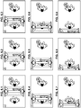
- the optical barriers 10, 20, 30, 40 corresponding to a deactivated position that is to say non-detection of an individual facing each other and in the form of blackened blocks, have been illustrated in the form of light-colored blocks, the activated barriers corresponding to the detection of an individual.
- the gantry according to the invention is further provided with logic means, integrated with the means 4, adapted to determine from the succession of activations of the barriers 10, 20, 30, 40, on the one hand the place and the displacement of any individual in the corridor or channel 5 of the gantry and secondly the existing correlations between the movement of an individual and the signals from the substance or material detection sensors.
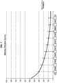
- the signal from the sensors of substances or materials gradually increases in correlation with the detection of an individual who crosses the gantry, the amplitude of the signal being maximum when the individual is detected leaving the gantry, it is probably in the presence of an individual carrying a substance or material to control that approaches the portico without having crossed it.
- optical barriers distributed along the direction of passage in the gantry at the rate of 2 optical barriers 10, 20 upstream of the detection sensors of substances or materials, either at the entry of the gantry, and 2 optical barriers downstream of the detection sensors of substances or materials, either at the exit of the gantry.
- the gap separating at least the two first barriers 10, 20 between them and the distance separating at least the last two barriers 30, 40 between them is such that an individual is still detected by the upstream barrier 10 or 30, for example when it is detected by the following barrier 20 or 40.
- This arrangement makes it possible to detect any suspicious non-regular movement of an individual within the gantry.
- the aforementioned provision also makes it possible to detect any attempt to go back in a portico that can be considered as suspicious behavior.
- the distance separating two successive barriers 10, 20, 30, 40 is preferably between 15 and 30 cm, typically of the order of 20 cm.
- the barriers 10, 20, 30, 40 may also be formed of a technology other than optical technology.
- the notion of "plurality of detection barriers distributed along the direction of passage in the gantry" must therefore be understood in a broad sense as encompassing any means to fulfill this function.
- the detection can also be enhanced or refined using a single camera correctly placed, whose resolution in pixels is adapted and which is coupled to means for processing the signal from the camera, to detect by pixel analysis the successive passage by a series of fictitious barriers corresponding to the location of the barriers described in the foregoing description.
- the gantry according to the present invention can be equipped with a Doppler type system to know the place and movement of an individual in the gantry.
Description
La présente invention concerne le domaine des portiques de contrôle d'accès.The present invention relates to the field of access control gantries.
L'invention trouve par exemple application dans le contrôle d'accès des salles d'embarquement d'aéroports ou de l'accès à des Administrations ou Institutions sensibles, sans que ces applications ne soient limitatives.The invention finds application, for example, in the access control of airport boarding gates or access to sensitive administrations or institutions, without these applications being limiting.
On a déjà proposé de nombreux portiques de contrôle d'accès de zones protégées.Many portals for access control of protected areas have already been proposed.
On trouvera des exemples de portiques de contrôle d'accès dans les documents
D'autres exemples de portiques sont décrits dans les documents
Généralement les portiques de contrôle d'accès définissent, comme illustré sur la
Ces capteurs peuvent comprendre des bobinages associés à des moyens 4 formant générateurs pour émettre un champ électromagnétique susceptible de détecter des métaux portés par des individus qui transitent par le portique, par analyse de perturbations détectées sur les bobinages par des moyens logiques intégrés aux moyens 4.These sensors may comprise coils associated with
Certains portiques sont également équipés de moyens d'analyse de substances ou molécules chimiques particulières, ou encore de rayonnements ionisants tel que des rayonnements gamma.Some gantries are also equipped with means of analysis of particular chemical substances or molecules, or ionizing radiation such as gamma radiation.
Les portiques de contrôle d'accès connus ont déjà rendu de grands services. Cependant ils ne donnent pas toujours totalement satisfaction.Known access control gates have already rendered great service. However, they do not always give complete satisfaction.
En particulier lors de flux de passages important, il arrive fréquemment que plusieurs individus qui se suivent à des distances rapprochées conduisent à des perturbations dans la détection en raison de leur proximité.Especially during large flow passages, it often happens that several individuals who follow each other at close distances lead to disturbances in the detection because of their proximity.
Il arrive en particulier que l'on attribue à un individu transitant par un portique une alarme liée en réalité à un individu qui le suit ou qui le précède.It happens in particular that we attribute to an individual transiting through a portico an alarm actually linked to an individual who follows or precedes him.
Les contrôles individuels qui sont alors nécessaires sont à la fois perturbants pour les individus concernés, complexes et sources de retard dans l'accès.The individual controls that are then necessary are both disturbing for the individuals concerned, complex and sources of delay in access.
La présente invention a pour but d'améliorer la situation.The present invention aims to improve the situation.
Ce but est atteint selon l'invention grâce à un portique de contrôle d'accès du type défini en revendication 1 annexée.This object is achieved according to the invention by means of an access control gantry of the type defined in appended
Selon d'autres caractéristiques avantageuses de l'invention :
- Les barrières de détection sont des barrières optiques,
- Le nombre de barrières de détection est supérieur à 3,
- Le nombre de barrières de détection est égal à 4,
- Il est prévu deux barrières en amont et deux barrières en aval des capteurs de détection,
- Les moyens logiques sont adaptés pour rechercher les corrélations existants entre les pics de signaux issus des capteurs de détection de substances ou matériaux et l'activation simultanée de deux barrières situées les plus au centre du passage défini dans le couloir ou canal du portique.
- Detection barriers are optical barriers,
- The number of detection barriers is greater than 3,
- The number of detection barriers is 4,
- Two barriers upstream and two barriers downstream of the detection sensors are provided.
- The logic means are adapted to search for existing correlations between the signal peaks from the detection sensors of substances or materials and the simultaneous activation of two barriers located most in the center of the passage defined in the corridor or channel of the gantry.
D'autres caractéristiques, buts et avantages de la présente invention apparaîtront à la lecture de la description détaillée qui va suivre et en regard des dessins annexés donnés à titre d'exemple non limitatif et sur lesquels :
- La
figure 1 représente une vue schématique en perspective d'un portique de contrôle d'accès connu de l'état de la technique, - Les
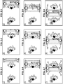
figures 2.1 à 2.9 représentent schématiquement 9 séquences successives de passage d'un portique par un individu dépourvu de substance ou matériau dangereux, suivi d'un individu portant une source de rayonnement ionisant, - La
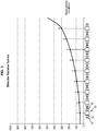
figure 3 illustre schématiquement la corrélation existant entre le signal issu d'un capteur de substances ou matériaux et l'activation des barrières de détection dans la suite des neuf séquences précitées, - Les
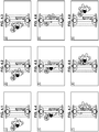
figures 4.1 à 4.9 représentent neuf séquences successives homologues de lafigure 2 dans la cas du passage à travers le portique d'un individu portant une source de rayonnement ionisant, - La
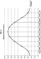
figure 5 représente la corrélation entre le signal issu d'un capteur de substances ou matériaux et l'activation des barrières dans la suite des neuf séquences desfigures 4 , - Les
figures 6.1 à 6.9 représentent neuf séquences successives illustrant le passage à travers le portique d'un individu dépourvu de matériau ou substance dangereuses, suivant un individu portant une source de rayonnement ionisant, et - La
figure 7 représente la corrélation existant entre le signal issu d'un capteur de substances ou matériaux et l'activation des barrières de détection correspondantes selon les séquences illustrées sur lesfigures 6 .
- The
figure 1 represents a schematic perspective view of an access control gantry known from the state of the art, - The
Figures 2.1 to 2.9 schematically represent 9 successive sequences of passage of a gantry by an individual devoid of dangerous substance or material, followed by an individual carrying a source of ionizing radiation, - The
figure 3 schematically illustrates the correlation existing between the signal from a sensor of substances or materials and the activation of the detection barriers in the sequence of the nine aforementioned sequences, - The
Figures 4.1 to 4.9 represent nine successive sequences homologous to thefigure 2 in the case of passage through the gantry of an individual carrying a source of ionizing radiation, - The
figure 5 represents the correlation between the signal from a sensor of substances or materials and the activation of the barriers in the sequence of the nine sequences offigures 4 , - The
Figures 6.1 to 6.9 represent nine successive sequences illustrating the passage through the gantry of an individual devoid of dangerous material or substance, according to an individual carrying a source of ionizing radiation, and - The
figure 7 represents the correlation existing between the signal coming from a sensor of substances or materials and the activation of the corresponding detection barriers according to the sequences illustrated on thefigures 6 .
La structure générale des portiques conformes à l'invention formés de deux panneaux ou colonnes 1, 2 encadrant un couloir ou canal de transfert 5 ainsi que les capteurs formant détecteur de métaux ou tout autre type de substances, y compris des rayonnements ionisant, notamment gamma, est connue de l'homme de l'art et ne sera pas décrite dans le détail par la suite.The general structure of the gantries according to the invention formed of two panels or
On pourra se référer à titre d'exemple non limitatif aux documents précités
Comme on le voit sur les
On entend par « réparties le long de la direction de passage dans le portique », une disposition des barrières 10, 20, 30, 40 telle que lesdites barrières sont successivement franchies lorsqu'un individu traverse normalement le portique en se déplaçant de l'entrée vers la sortie, voire dans le sens inverse."Distributed along the direction of passage in the portico" is understood to mean a disposition of the
Chaque barrière optique 10, 20, 30, 40 est de préférence formée d'une cellule émettrice 10a, 20a, 30a, 40a située d'un côté du couloir ou canal de passage et d'une cellule réceptrice respectivement associée 10b, 20b, 30b, 40b située sur le côté opposé.Each
Plus précisément les cellules émettrices et réceptrices 10a, 20a, 30a, 40a ; 10b, 20b, 30b, 40b peuvent être formées d'une barrette définissant un rideau optique globalement vertical couvrant l'essentiel de la hauteur du couloir ou canal de transfert 5. En variante chaque barrière optique 10, 20, 30, 40 peut être formée d'une pluralité de cellules émettrices 10a, 20a, 30a, 40a et de cellules réceptrices respectives 10b, 20b, 30b, 40b réparties sur la hauteur du couloir ou canal 5 afin de détecter en toute certitude le passage d'un individu quelle que soit la position de celui-ci, c'est-à-dire que l'individu se tienne en position debout normale ou par exemple dans une position recroquevillée voire allongée quelconque.More precisely, the emitter and
Sur les
Sur les
L'homme de l'art comprendra à l'examen de la
L'on observera à l'examen des
Enfin l'on comprendra à l'examen des
Le portique conforme à l'invention est en outre pourvu de moyens logiques, intégrés aux moyens 4, adaptés pour déterminer à partir de la succession d'activations des barrières 10, 20, 30, 40, d'une part la place et le déplacement d'un individu quelconque dans le couloir ou canal 5 du portique et d'autre part les corrélations existantes entre le déplacement d'un individu et les signaux issus des capteurs de détection de substance ou de matériau.The gantry according to the invention is further provided with logic means, integrated with the
Lorsque comme il est illustré sur les
Lorsque comme illustré sur les
Enfin comme illustré sur les
Dans le cadre de l'invention comme montré sur les figures il est prévu de préférence un nombre de barrières supérieur à 3 pour permettre une détection fine de la localisation d'un individu lors du franchissement d'un portique.In the context of the invention as shown in the figures it is preferably provided a number of barriers greater than 3 to allow a fine detection of the location of an individual when crossing a gantry.
Plus précisément dans le cadre de l'invention il est prévu de préférence 4 barrières optiques réparties le long de la direction de passage dans le portique à raison de 2 barrières optiques 10, 20 en amont des capteurs de détection de substances ou matériaux, soit à l'entrée du portique, et 2 barrières optiques en aval des capteurs de détection de substances ou de matériaux, soit à la sortie du portique.More precisely in the context of the invention is preferably provided 4 optical barriers distributed along the direction of passage in the gantry at the rate of 2
Ainsi lors d'un passage normal à travers un couloir 5 du portique, de l'entrée vers la sortie, un individu est successivement détecté par la barrière d'entrée 10, puis la deuxième barrière 20, la troisième barrière 30 et enfin la barrière de sortie 40.Thus during a normal passage through a
Plus précisément encore selon la présente invention, de préférence l'écart séparant au moins les deux premières barrières 10, 20 entre elles et la distance séparant au moins les deux dernières barrières 30, 40 entre elles est telle qu'un individu est encore détecté par la barrière amont 10 ou 30 par exemple lorsqu'il est détecté par la barrière suivante 20 ou 40. Cette disposition permet de détecter tout déplacement suspect non régulier d'un individu au sein du portique.More precisely still according to the present invention, preferably the gap separating at least the two
La disposition précitée permet également de détecter toute tentative de retour en arrière au sein d'un portique qui peut être considérée comme un comportement suspect.The aforementioned provision also makes it possible to detect any attempt to go back in a portico that can be considered as suspicious behavior.
En pratique la distance séparant deux barrières successives 10, 20, 30, 40 est de préférence comprise entre 15 et 30cm, typiquement de l'ordre de 20 cm.In practice, the distance separating two
Bien entendu la présente invention n'est pas limitée aux modes de réalisations particuliers qui viennent d'être décrits mais s'étend à toute variante conforme à son esprit.Naturally, the present invention is not limited to the particular embodiments that have just been described, but extends to any variant within its spirit.
En particulier on peut bien entendu prévoir un nombre de barrières optiques différent du mode de réalisation préférentiel précédemment décrit, tout particulièrement un nombre de barrières supérieur à 4.In particular, it is of course possible to provide a number of optical barriers different from the preferred embodiment previously described, in particular a number of barriers greater than 4.
Le cas échéant les barrières 10, 20, 30, 40 peuvent également être formées d'une autre technologie que la technologie optique. La notion de « pluralité de barrières de détection réparties le long de la direction de passage dans le portique » doit donc être comprise dans un sens large comme englobant tous moyens permettant de remplir cette fonction. La détection peut également être renforcée ou affinée à l'aide d'une caméra unique correctement placée, dont la résolution en pixels est adaptée et qui est couplée à des moyens de traitement du signal issu de la caméra, permettant de détecter par analyse de pixels le passage successif par une suite de barrières fictives correspondant à la localisation des barrières décrites dans la description qui précède.Where appropriate, the
De même le portique conforme à la présente invention peut être équipé d'un système de type Doppler permettant de connaître la place et le déplacement d'un individu dans le portique.Similarly, the gantry according to the present invention can be equipped with a Doppler type system to know the place and movement of an individual in the gantry.
Claims (16)
- An individual access control portal comprising two panels or columns (1, 2) that define a through corridor, which panels or columns (1, 2) are equipped with sensors adapted to detect substances or materials liable to be carried by individuals travelling through the portal, the portal being equipped with a plurality of individual detection barriers (10, 20, 30, 40) distributed along the direction of passage through the portal and logic means (4) attached to the plurality of barriers,
characterized in that said logic means (4) are adapted firstly to determine from the series of activations of said barriers (10, 20, 30, 40) the place and movement of an individual and secondly to establish the correlations existing between the movement of an individual and the signals output by the substance or material detection sensors, the logic means (4) being adapted to detect the correlation between a peak output by the substance or material sensors and the simultaneous activation of two barriers (20, 30) located the nearest to the center of the portal. - The portal according to claim 1, characterized in that the barriers (10, 20, 30, 40) are optical barriers.
- The portal according to any one of claims 1 or 2, characterized in that the number of the barriers (10, 20, 30, 40) is greater than 3.
- The portal according to any one of claims 1 to 3, characterized in that the number of the barriers (10, 20, 30, 40) is equal to 4.
- The portal according to any one of claims 1 to 4, characterized in that it comprises two barriers (10, 20) upstream of the substance or material sensors and two barriers (30, 40) downstream of the substance or material sensors.
- The portal according to any one of claims 1 to 5, characterized in that the distance separating two successive barriers (10, 20, 30, 40) in the direction of passage along the corridor or channel (5) of the portal is between 15 and 30 centimeters, typically in the order of 20 centimeters.
- The portal according to any one of claims 1 to 6, characterized in that each barrier (10, 20, 30, 40) is adapted to provide detection over almost the whole height of the passage corridor or channel (5).
- The portal according to any one of claims 1 to 7, characterized in that the barriers are optical barriers (10, 20, 30, 40) and each optical barrier (10, 20, 30, 40) is formed by a detection curtain making it possible to cover almost the whole height of the passage corridor or channel (5).
- The portal according to any one of claims 1 to 7, characterized in that the barriers (10, 20, 30, 40) are optical barriers and each optical barrier (10, 20, 30, 40) is formed by a plurality of intermittent beams making it possible to cover almost the whole height of the passage corridor or channel (5).
- The portal according to any one of claims 1 to 9, characterized in that the logic means (4) are adapted to detect the successive crossing of the different detection barriers (10, 20, 30, 40) distributed along the direction of passage through the portal.
- The portal according to any one of claims 1 to 10, characterized in that the logic means (4) are adapted to detect the successive crossing of a first entrance barrier (10), then a second barrier (20), and so on up to an exit barrier (40).
- The portal according to any one of claims 1 to 11, characterized in that the gap separating at least two first barriers (10, 20) from each other and the distance separating at least two last barriers (30, 40) from each other are such that an individual is still detected by an upstream barrier (10, 30) when it is detected by the next barrier (20, 40).
- The portal according to any one of claims 1 to 12, characterized in that the logic means (4) are adapted to identify an attempt to return backwards inside the portal, when the detection does not correspond to a successive crossing of the different detection barriers (10, 20, 30, 40) distributed along the direction of passage through the portal.
- The portal according to any one of claims 1 to 13, characterized in that the logic means (4) are adapted to identify a state of presence of an individual carrying a substance or material to be checked is approaching the portal without having crossed it, when the signal output by the substance or material detection sensors gradually increases in correlation with the detection of an individual crossing the portal, the amplitude of the signal being at a maximum when the individual is detected exiting the portal.
- The portal according to any one of claims 1 to 14, characterized in that the logic means (4) are adapted to identify a state of presence of an individual crossing the portal and carrying a substance or material to be checked, when the signal output by the substance or material detection sensors increases until an individual is located at the center of the portal, and then gradually decreases when the individual leaves the portal.
- The portal according to any one of claims 1 to 14, characterized in that the logic means (4) are adapted to identify a state of presence of an individual who has previously cross the portal and is carrying a substance or material to be checked, when the signal output by the substance or material detection sensors gradually decreases upon detection of the crossing of the portal by an individual.
Priority Applications (1)
| Application Number | Priority Date | Filing Date | Title |
|---|---|---|---|
| PL15180473T PL2985635T3 (en) | 2014-08-14 | 2015-08-11 | Access control gate |
Applications Claiming Priority (1)
| Application Number | Priority Date | Filing Date | Title |
|---|---|---|---|
| FR1457832A FR3024909A1 (en) | 2014-08-14 | 2014-08-14 | ACCESS CONTROL PORTIC |
Publications (3)
| Publication Number | Publication Date |
|---|---|
| EP2985635A2 EP2985635A2 (en) | 2016-02-17 |
| EP2985635A3 EP2985635A3 (en) | 2016-06-29 |
| EP2985635B1 true EP2985635B1 (en) | 2018-08-01 |
Family
ID=52358850
Family Applications (1)
| Application Number | Title | Priority Date | Filing Date |
|---|---|---|---|
| EP15180473.9A Active EP2985635B1 (en) | 2014-08-14 | 2015-08-11 | Access control gate |
Country Status (8)
| Country | Link |
|---|---|
| US (1) | US10107933B2 (en) |
| EP (1) | EP2985635B1 (en) |
| CA (1) | CA2900233C (en) |
| DK (1) | DK2985635T3 (en) |
| ES (1) | ES2691987T3 (en) |
| FR (1) | FR3024909A1 (en) |
| PL (1) | PL2985635T3 (en) |
| TR (1) | TR201816310T4 (en) |
Families Citing this family (1)
| Publication number | Priority date | Publication date | Assignee | Title |
|---|---|---|---|---|
| FR3072468B1 (en) * | 2017-10-13 | 2020-02-14 | Alessandro Manneschi | DEVICE AND METHOD FOR DETECTING UNAUTHORIZED OBJECTS OR MATERIALS CARRIED BY AN INDIVIDUAL IN A PROTECTED ACCESS AREA |
Family Cites Families (15)
| Publication number | Priority date | Publication date | Assignee | Title |
|---|---|---|---|---|
| ITTO980146A1 (en) | 1998-02-25 | 1999-08-25 | Alessandro Manneschi | DETECTOR SYSTEM FOR ACCESS CONTROL AND RELATIVE DETECTOR GROUP. |
| US6094472A (en) * | 1998-04-14 | 2000-07-25 | Rapiscan Security Products, Inc. | X-ray backscatter imaging system including moving body tracking assembly |
| ITAR20020029A1 (en) | 2002-08-21 | 2004-02-22 | Alessandro Manneschi | METAL DETECTOR AND VERIFICATION PROCEDURE FOR THE SAME |
| FR2888340B1 (en) | 2005-07-11 | 2007-10-19 | Alessandro Manneschi | TEST DEVICE FOR PORTIC DETECTOR OF METALS |
| EP1750148A1 (en) | 2005-08-04 | 2007-02-07 | Giovanni Manneschi | Metal detector presenting high performance |
| ES2476025T3 (en) | 2005-08-04 | 2014-07-11 | Alessandro Manneschi | Metal detector |
| EP1750149B1 (en) | 2005-08-04 | 2017-05-10 | M. Alessandro Manneschi | Metal detector |
| FR2901888B1 (en) | 2006-05-30 | 2008-08-22 | Alessandro Manneschi | PORTE DETECTOR OF METALS HAVING PERFECTED INDICATOR MEANS |
| CN101162507B (en) * | 2006-10-13 | 2010-05-12 | 同方威视技术股份有限公司 | Method for recognizing vehicle type of moving care |
| FR2914998B1 (en) | 2007-04-12 | 2009-07-03 | Alessandro Manneschi | DEVICE FOR ANALYZING THE COMPOSITION OF THE CONTENT OF A CONTAINER COMPRISING MEANS FOR OBTAINING AT LEAST ONE ADDITIONAL PHYSICAL DATA RELATING TO THE CONTAINER |
| ES2394120T3 (en) | 2008-12-24 | 2013-01-21 | Alessandro Manneschi | System to control a person |
| ATE553397T1 (en) * | 2008-12-30 | 2012-04-15 | Sony Corp | CAMERA-ASSISTED SCANNING IMAGING SYSTEM AND MULTI-ASPECT IMAGING SYSTEM |
| EP2402914A1 (en) * | 2010-06-29 | 2012-01-04 | Luca Manneschi | Detector for the inspection of people |
| FR3009381B1 (en) | 2013-08-05 | 2015-08-21 | Elettroniche Ind Automatismi S P A C E I A S P A Costruzioni | PORTABLE DETECTION DETECTOR FOR METALS INCLUDING AN ADVANCED AUTOMATIC SUSTAINING SYSTEM |
| FR3009383B1 (en) | 2013-08-05 | 2016-01-01 | Elettroniche Ind Automatismi S P A C E I A S P A Costruzioni | PORTABLE DETECTOR OF PERFECTED METAL |
-
2014
- 2014-08-14 FR FR1457832A patent/FR3024909A1/en not_active Withdrawn
-
2015
- 2015-08-11 TR TR2018/16310T patent/TR201816310T4/en unknown
- 2015-08-11 ES ES15180473.9T patent/ES2691987T3/en active Active
- 2015-08-11 EP EP15180473.9A patent/EP2985635B1/en active Active
- 2015-08-11 PL PL15180473T patent/PL2985635T3/en unknown
- 2015-08-11 DK DK15180473.9T patent/DK2985635T3/en active
- 2015-08-12 CA CA2900233A patent/CA2900233C/en active Active
- 2015-08-13 US US14/825,381 patent/US10107933B2/en active Active
Non-Patent Citations (1)
| Title |
|---|
| None * |
Also Published As
| Publication number | Publication date |
|---|---|
| CA2900233C (en) | 2018-05-01 |
| EP2985635A3 (en) | 2016-06-29 |
| US20160047937A1 (en) | 2016-02-18 |
| ES2691987T3 (en) | 2018-11-29 |
| PL2985635T3 (en) | 2019-01-31 |
| CA2900233A1 (en) | 2016-02-14 |
| US10107933B2 (en) | 2018-10-23 |
| TR201816310T4 (en) | 2018-11-21 |
| EP2985635A2 (en) | 2016-02-17 |
| FR3024909A1 (en) | 2016-02-19 |
| DK2985635T3 (en) | 2018-10-22 |
Similar Documents
| Publication | Publication Date | Title |
|---|---|---|
| CA2589923C (en) | Metal detecting portal with enhanced indicator means | |
| WO2005098401A3 (en) | Method ans system for automatically scanning and imaging the contents of a moving target | |
| EP2089736A2 (en) | Goniometric system comprising networks of mini doppler sensors for perimeter surveillance | |
| CA3127752A1 (en) | Double-field security body scanner | |
| EP2985635B1 (en) | Access control gate | |
| FR3072468A1 (en) | DEVICE AND METHOD FOR DETECTING UNAUTHORIZED OBJECTS OR MATERIALS USED BY AN INDIVIDUAL IN A PROTECTED ACCESS AREA | |
| EP3067661B1 (en) | Method for controlling a network of dynamic direction signage devices and guiding system configured to implement such a method | |
| FR2608777A1 (en) | DEVICE FOR DETECTION OF INTRUSION AND RECOGNITION OF TERRESTRIAL VEHICLES | |
| FR2959020A1 (en) | DEVICE FOR INSTANTANEOUS DETECTION OF 360-DEGREE IMAGERY HIDED OBJECTS | |
| EP3234644B1 (en) | Method for detecting moving elements in a building and apparatus for implementing said method | |
| EP3814808A1 (en) | Portable detection system comprising magnetostatic sensors | |
| EP3918377B1 (en) | Improved metal-detector means for locating the presence of metallic objects | |
| WO2009086928A1 (en) | Detection method, system and installation for ensuring the passage of only one object | |
| CA3106492A1 (en) | Combined detector for detecting metals and magnetised target objects | |
| EP1581911A1 (en) | Access control system | |
| WO2019217779A3 (en) | Screening system | |
| FR2871602A1 (en) | Person`s physical access controlling device for e.g. nuclear center, has control electronics unit determining whether pressure measurement relate to step of one or multiple persons and activating alarm in case of passage of multiple persons | |
| WO2007065979A1 (en) | Device for controlling physical access of persons with verification of uniqueness of presence and of transit | |
| CA3104582A1 (en) | Portable detection system comprising magnetostatic sensors | |
| FR2782384A1 (en) | Rain measuring device to determine spread and raindrop speed over given area and arrival time of rain drops, for real time analysis of meteorological conditions | |
| EP4080177B1 (en) | Method and system for controlling the maximum noise level related to the movement of a vehicle | |
| FR3072783B1 (en) | IONIZING RADIATION DETECTION SYSTEM AND ASSOCIATED DETECTION METHOD | |
| FR2968089A1 (en) | PANORAMIC LASERS PULSE DETECTION DEVICE. | |
| FR2887061A1 (en) | METHOD FOR ANALYZING A PRESENCE IN A SPACE | |
| EP1726942A2 (en) | Object detector using microwave frequency echoes analysis |
Legal Events
| Date | Code | Title | Description |
|---|---|---|---|
| PUAI | Public reference made under article 153(3) epc to a published international application that has entered the european phase |
Free format text: ORIGINAL CODE: 0009012 |
|
| 17P | Request for examination filed |
Effective date: 20150811 |
|
| AK | Designated contracting states |
Kind code of ref document: A2 Designated state(s): AL AT BE BG CH CY CZ DE DK EE ES FI FR GB GR HR HU IE IS IT LI LT LU LV MC MK MT NL NO PL PT RO RS SE SI SK SM TR |
|
| AX | Request for extension of the european patent |
Extension state: BA ME |
|
| PUAL | Search report despatched |
Free format text: ORIGINAL CODE: 0009013 |
|
| AK | Designated contracting states |
Kind code of ref document: A3 Designated state(s): AL AT BE BG CH CY CZ DE DK EE ES FI FR GB GR HR HU IE IS IT LI LT LU LV MC MK MT NL NO PL PT RO RS SE SI SK SM TR |
|
| AX | Request for extension of the european patent |
Extension state: BA ME |
|
| RIC1 | Information provided on ipc code assigned before grant |
Ipc: G01V 3/10 20060101ALN20160520BHEP Ipc: G01V 8/20 20060101AFI20160520BHEP Ipc: G01T 1/167 20060101ALI20160520BHEP |
|
| 17Q | First examination report despatched |
Effective date: 20170519 |
|
| REG | Reference to a national code |
Ref country code: DE Ref legal event code: R079 Ref document number: 602015014203 Country of ref document: DE Free format text: PREVIOUS MAIN CLASS: G01V0008100000 Ipc: G01V0008200000 |
|
| RIC1 | Information provided on ipc code assigned before grant |
Ipc: G01V 8/20 20060101AFI20180221BHEP Ipc: G01T 1/167 20060101ALI20180221BHEP Ipc: G01V 3/10 20060101ALN20180221BHEP |
|
| GRAP | Despatch of communication of intention to grant a patent |
Free format text: ORIGINAL CODE: EPIDOSNIGR1 |
|
| RIC1 | Information provided on ipc code assigned before grant |
Ipc: G01V 8/20 20060101AFI20180313BHEP Ipc: G01T 1/167 20060101ALI20180313BHEP Ipc: G01V 3/10 20060101ALN20180313BHEP |
|
| INTG | Intention to grant announced |
Effective date: 20180403 |
|
| RIC1 | Information provided on ipc code assigned before grant |
Ipc: G01V 3/10 20060101ALN20180320BHEP Ipc: G01T 1/167 20060101ALI20180320BHEP Ipc: G01V 8/20 20060101AFI20180320BHEP |
|
| GRAS | Grant fee paid |
Free format text: ORIGINAL CODE: EPIDOSNIGR3 |
|
| GRAA | (expected) grant |
Free format text: ORIGINAL CODE: 0009210 |
|
| AK | Designated contracting states |
Kind code of ref document: B1 Designated state(s): AL AT BE BG CH CY CZ DE DK EE ES FI FR GB GR HR HU IE IS IT LI LT LU LV MC MK MT NL NO PL PT RO RS SE SI SK SM TR |
|
| REG | Reference to a national code |
Ref country code: GB Ref legal event code: FG4D Free format text: NOT ENGLISH |
|
| REG | Reference to a national code |
Ref country code: CH Ref legal event code: EP Ref country code: AT Ref legal event code: REF Ref document number: 1024950 Country of ref document: AT Kind code of ref document: T Effective date: 20180815 |
|
| REG | Reference to a national code |
Ref country code: IE Ref legal event code: FG4D Free format text: LANGUAGE OF EP DOCUMENT: FRENCH |
|
| REG | Reference to a national code |
Ref country code: DE Ref legal event code: R096 Ref document number: 602015014203 Country of ref document: DE |
|
| REG | Reference to a national code |
Ref country code: FR Ref legal event code: PLFP Year of fee payment: 4 |
|
| REG | Reference to a national code |
Ref country code: RO Ref legal event code: EPE |
|
| REG | Reference to a national code |
Ref country code: CH Ref legal event code: NV Representative=s name: MICHELI AND CIE SA, CH |
|
| REG | Reference to a national code |
Ref country code: DK Ref legal event code: T3 Effective date: 20181015 |
|
| REG | Reference to a national code |
Ref country code: NL Ref legal event code: FP |
|
| REG | Reference to a national code |
Ref country code: SE Ref legal event code: TRGR |
|
| REG | Reference to a national code |
Ref country code: ES Ref legal event code: FG2A Ref document number: 2691987 Country of ref document: ES Kind code of ref document: T3 Effective date: 20181129 |
|
| REG | Reference to a national code |
Ref country code: LT Ref legal event code: MG4D |
|
| PG25 | Lapsed in a contracting state [announced via postgrant information from national office to epo] |
Ref country code: IS Free format text: LAPSE BECAUSE OF FAILURE TO SUBMIT A TRANSLATION OF THE DESCRIPTION OR TO PAY THE FEE WITHIN THE PRESCRIBED TIME-LIMIT Effective date: 20181201 Ref country code: BG Free format text: LAPSE BECAUSE OF FAILURE TO SUBMIT A TRANSLATION OF THE DESCRIPTION OR TO PAY THE FEE WITHIN THE PRESCRIBED TIME-LIMIT Effective date: 20181101 Ref country code: GR Free format text: LAPSE BECAUSE OF FAILURE TO SUBMIT A TRANSLATION OF THE DESCRIPTION OR TO PAY THE FEE WITHIN THE PRESCRIBED TIME-LIMIT Effective date: 20181102 Ref country code: NO Free format text: LAPSE BECAUSE OF FAILURE TO SUBMIT A TRANSLATION OF THE DESCRIPTION OR TO PAY THE FEE WITHIN THE PRESCRIBED TIME-LIMIT Effective date: 20181101 Ref country code: RS Free format text: LAPSE BECAUSE OF FAILURE TO SUBMIT A TRANSLATION OF THE DESCRIPTION OR TO PAY THE FEE WITHIN THE PRESCRIBED TIME-LIMIT Effective date: 20180801 Ref country code: LT Free format text: LAPSE BECAUSE OF FAILURE TO SUBMIT A TRANSLATION OF THE DESCRIPTION OR TO PAY THE FEE WITHIN THE PRESCRIBED TIME-LIMIT Effective date: 20180801 |
|
| PG25 | Lapsed in a contracting state [announced via postgrant information from national office to epo] |
Ref country code: HR Free format text: LAPSE BECAUSE OF FAILURE TO SUBMIT A TRANSLATION OF THE DESCRIPTION OR TO PAY THE FEE WITHIN THE PRESCRIBED TIME-LIMIT Effective date: 20180801 Ref country code: AL Free format text: LAPSE BECAUSE OF FAILURE TO SUBMIT A TRANSLATION OF THE DESCRIPTION OR TO PAY THE FEE WITHIN THE PRESCRIBED TIME-LIMIT Effective date: 20180801 Ref country code: LV Free format text: LAPSE BECAUSE OF FAILURE TO SUBMIT A TRANSLATION OF THE DESCRIPTION OR TO PAY THE FEE WITHIN THE PRESCRIBED TIME-LIMIT Effective date: 20180801 |
|
| PG25 | Lapsed in a contracting state [announced via postgrant information from national office to epo] |
Ref country code: CZ Free format text: LAPSE BECAUSE OF FAILURE TO SUBMIT A TRANSLATION OF THE DESCRIPTION OR TO PAY THE FEE WITHIN THE PRESCRIBED TIME-LIMIT Effective date: 20180801 Ref country code: MC Free format text: LAPSE BECAUSE OF FAILURE TO SUBMIT A TRANSLATION OF THE DESCRIPTION OR TO PAY THE FEE WITHIN THE PRESCRIBED TIME-LIMIT Effective date: 20180801 Ref country code: EE Free format text: LAPSE BECAUSE OF FAILURE TO SUBMIT A TRANSLATION OF THE DESCRIPTION OR TO PAY THE FEE WITHIN THE PRESCRIBED TIME-LIMIT Effective date: 20180801 Ref country code: LU Free format text: LAPSE BECAUSE OF NON-PAYMENT OF DUE FEES Effective date: 20180811 |
|
| REG | Reference to a national code |
Ref country code: DE Ref legal event code: R097 Ref document number: 602015014203 Country of ref document: DE |
|
| PG25 | Lapsed in a contracting state [announced via postgrant information from national office to epo] |
Ref country code: SK Free format text: LAPSE BECAUSE OF FAILURE TO SUBMIT A TRANSLATION OF THE DESCRIPTION OR TO PAY THE FEE WITHIN THE PRESCRIBED TIME-LIMIT Effective date: 20180801 Ref country code: SM Free format text: LAPSE BECAUSE OF FAILURE TO SUBMIT A TRANSLATION OF THE DESCRIPTION OR TO PAY THE FEE WITHIN THE PRESCRIBED TIME-LIMIT Effective date: 20180801 |
|
| PLBE | No opposition filed within time limit |
Free format text: ORIGINAL CODE: 0009261 |
|
| STAA | Information on the status of an ep patent application or granted ep patent |
Free format text: STATUS: NO OPPOSITION FILED WITHIN TIME LIMIT |
|
| 26N | No opposition filed |
Effective date: 20190503 |
|
| REG | Reference to a national code |
Ref country code: AT Ref legal event code: UEP Ref document number: 1024950 Country of ref document: AT Kind code of ref document: T Effective date: 20180801 |
|
| PG25 | Lapsed in a contracting state [announced via postgrant information from national office to epo] |
Ref country code: SI Free format text: LAPSE BECAUSE OF FAILURE TO SUBMIT A TRANSLATION OF THE DESCRIPTION OR TO PAY THE FEE WITHIN THE PRESCRIBED TIME-LIMIT Effective date: 20180801 |
|
| PG25 | Lapsed in a contracting state [announced via postgrant information from national office to epo] |
Ref country code: MT Free format text: LAPSE BECAUSE OF FAILURE TO SUBMIT A TRANSLATION OF THE DESCRIPTION OR TO PAY THE FEE WITHIN THE PRESCRIBED TIME-LIMIT Effective date: 20180801 |
|
| PG25 | Lapsed in a contracting state [announced via postgrant information from national office to epo] |
Ref country code: PT Free format text: LAPSE BECAUSE OF FAILURE TO SUBMIT A TRANSLATION OF THE DESCRIPTION OR TO PAY THE FEE WITHIN THE PRESCRIBED TIME-LIMIT Effective date: 20180801 |
|
| PG25 | Lapsed in a contracting state [announced via postgrant information from national office to epo] |
Ref country code: MK Free format text: LAPSE BECAUSE OF NON-PAYMENT OF DUE FEES Effective date: 20180801 Ref country code: CY Free format text: LAPSE BECAUSE OF FAILURE TO SUBMIT A TRANSLATION OF THE DESCRIPTION OR TO PAY THE FEE WITHIN THE PRESCRIBED TIME-LIMIT Effective date: 20180801 Ref country code: HU Free format text: LAPSE BECAUSE OF FAILURE TO SUBMIT A TRANSLATION OF THE DESCRIPTION OR TO PAY THE FEE WITHIN THE PRESCRIBED TIME-LIMIT; INVALID AB INITIO Effective date: 20150811 |
|
| PGFP | Annual fee paid to national office [announced via postgrant information from national office to epo] |
Ref country code: NL Payment date: 20230726 Year of fee payment: 9 |
|
| PGFP | Annual fee paid to national office [announced via postgrant information from national office to epo] |
Ref country code: TR Payment date: 20230727 Year of fee payment: 9 Ref country code: RO Payment date: 20230801 Year of fee payment: 9 Ref country code: IT Payment date: 20230809 Year of fee payment: 9 Ref country code: IE Payment date: 20230721 Year of fee payment: 9 Ref country code: GB Payment date: 20230824 Year of fee payment: 9 Ref country code: FI Payment date: 20230724 Year of fee payment: 9 Ref country code: ES Payment date: 20230907 Year of fee payment: 9 Ref country code: CH Payment date: 20230902 Year of fee payment: 9 Ref country code: AT Payment date: 20230724 Year of fee payment: 9 |
|
| PGFP | Annual fee paid to national office [announced via postgrant information from national office to epo] |
Ref country code: SE Payment date: 20230816 Year of fee payment: 9 Ref country code: PL Payment date: 20230720 Year of fee payment: 9 Ref country code: FR Payment date: 20230710 Year of fee payment: 9 Ref country code: DK Payment date: 20230728 Year of fee payment: 9 Ref country code: DE Payment date: 20230808 Year of fee payment: 9 Ref country code: BE Payment date: 20230822 Year of fee payment: 9 |