EP2985581A1 - Small form factor pressure sensor - Google Patents
Small form factor pressure sensor Download PDFInfo
- Publication number
- EP2985581A1 EP2985581A1 EP15176872.8A EP15176872A EP2985581A1 EP 2985581 A1 EP2985581 A1 EP 2985581A1 EP 15176872 A EP15176872 A EP 15176872A EP 2985581 A1 EP2985581 A1 EP 2985581A1
- Authority
- EP
- European Patent Office
- Prior art keywords
- pressure sensor
- spring
- housing interlocking
- coiled
- housing
- Prior art date
- Legal status (The legal status is an assumption and is not a legal conclusion. Google has not performed a legal analysis and makes no representation as to the accuracy of the status listed.)
- Granted
Links
- 238000009434 installation Methods 0.000 claims description 4
- 230000009977 dual effect Effects 0.000 claims description 3
- 230000013011 mating Effects 0.000 claims description 3
- 229910052751 metal Inorganic materials 0.000 claims description 3
- 239000002184 metal Substances 0.000 claims description 3
- 238000002347 injection Methods 0.000 claims description 2
- 239000007924 injection Substances 0.000 claims description 2
- 230000014759 maintenance of location Effects 0.000 claims description 2
- 238000004519 manufacturing process Methods 0.000 claims description 2
- 239000002991 molded plastic Substances 0.000 claims description 2
- 238000004804 winding Methods 0.000 claims description 2
- XUIMIQQOPSSXEZ-UHFFFAOYSA-N Silicon Chemical compound [Si] XUIMIQQOPSSXEZ-UHFFFAOYSA-N 0.000 abstract description 2
- 229910052710 silicon Inorganic materials 0.000 abstract description 2
- 239000010703 silicon Substances 0.000 abstract description 2
- 239000004033 plastic Substances 0.000 description 9
- WBHQEUPUMONIKF-UHFFFAOYSA-N PCB180 Chemical compound C1=C(Cl)C(Cl)=CC(Cl)=C1C1=CC(Cl)=C(Cl)C(Cl)=C1Cl WBHQEUPUMONIKF-UHFFFAOYSA-N 0.000 description 3
- 229910001220 stainless steel Inorganic materials 0.000 description 2
- 239000010935 stainless steel Substances 0.000 description 2
- BQCADISMDOOEFD-UHFFFAOYSA-N Silver Chemical compound [Ag] BQCADISMDOOEFD-UHFFFAOYSA-N 0.000 description 1
- 230000005540 biological transmission Effects 0.000 description 1
- 238000010586 diagram Methods 0.000 description 1
- 238000005516 engineering process Methods 0.000 description 1
- 239000000446 fuel Substances 0.000 description 1
- 238000000034 method Methods 0.000 description 1
- 238000012986 modification Methods 0.000 description 1
- 230000004048 modification Effects 0.000 description 1
- 229910052709 silver Inorganic materials 0.000 description 1
- 239000004332 silver Substances 0.000 description 1
- 239000000243 solution Substances 0.000 description 1
Images


Classifications
-
- G—PHYSICS
- G01—MEASURING; TESTING
- G01L—MEASURING FORCE, STRESS, TORQUE, WORK, MECHANICAL POWER, MECHANICAL EFFICIENCY, OR FLUID PRESSURE
- G01L19/00—Details of, or accessories for, apparatus for measuring steady or quasi-steady pressure of a fluent medium insofar as such details or accessories are not special to particular types of pressure gauges
- G01L19/0061—Electrical connection means
-
- G—PHYSICS
- G01—MEASURING; TESTING
- G01L—MEASURING FORCE, STRESS, TORQUE, WORK, MECHANICAL POWER, MECHANICAL EFFICIENCY, OR FLUID PRESSURE
- G01L19/00—Details of, or accessories for, apparatus for measuring steady or quasi-steady pressure of a fluent medium insofar as such details or accessories are not special to particular types of pressure gauges
- G01L19/0061—Electrical connection means
- G01L19/0069—Electrical connection means from the sensor to its support
-
- G—PHYSICS
- G01—MEASURING; TESTING
- G01L—MEASURING FORCE, STRESS, TORQUE, WORK, MECHANICAL POWER, MECHANICAL EFFICIENCY, OR FLUID PRESSURE
- G01L19/00—Details of, or accessories for, apparatus for measuring steady or quasi-steady pressure of a fluent medium insofar as such details or accessories are not special to particular types of pressure gauges
- G01L19/14—Housings
- G01L19/147—Details about the mounting of the sensor to support or covering means
-
- G—PHYSICS
- G01—MEASURING; TESTING
- G01L—MEASURING FORCE, STRESS, TORQUE, WORK, MECHANICAL POWER, MECHANICAL EFFICIENCY, OR FLUID PRESSURE
- G01L19/00—Details of, or accessories for, apparatus for measuring steady or quasi-steady pressure of a fluent medium insofar as such details or accessories are not special to particular types of pressure gauges
- G01L19/14—Housings
- G01L19/148—Details about the circuit board integration, e.g. integrated with the diaphragm surface or encapsulation
-
- G—PHYSICS
- G01—MEASURING; TESTING
- G01R—MEASURING ELECTRIC VARIABLES; MEASURING MAGNETIC VARIABLES
- G01R1/00—Details of instruments or arrangements of the types included in groups G01R5/00 - G01R13/00 and G01R31/00
- G01R1/02—General constructional details
- G01R1/06—Measuring leads; Measuring probes
- G01R1/067—Measuring probes
- G01R1/06711—Probe needles; Cantilever beams; "Bump" contacts; Replaceable probe pins
- G01R1/06716—Elastic
-
- H—ELECTRICITY
- H01—ELECTRIC ELEMENTS
- H01R—ELECTRICALLY-CONDUCTIVE CONNECTIONS; STRUCTURAL ASSOCIATIONS OF A PLURALITY OF MUTUALLY-INSULATED ELECTRICAL CONNECTING ELEMENTS; COUPLING DEVICES; CURRENT COLLECTORS
- H01R13/00—Details of coupling devices of the kinds covered by groups H01R12/70 or H01R24/00 - H01R33/00
- H01R13/02—Contact members
- H01R13/22—Contacts for co-operating by abutting
- H01R13/24—Contacts for co-operating by abutting resilient; resiliently-mounted
- H01R13/2407—Contacts for co-operating by abutting resilient; resiliently-mounted characterized by the resilient means
- H01R13/2421—Contacts for co-operating by abutting resilient; resiliently-mounted characterized by the resilient means using coil springs
Definitions
- the invention relates generally to pressure sensors, and more specifically to a small form factor pressure sensor.
- MSG Microfused Silicon Strain gage
- a preferred design for a small form factor MSG sensor which can have an outside diameter of less than 15mm, typically uses a single printed circuit board (PCB) that connects directly to customer electronics in order to minimize component count.
- PCB printed circuit board
- a location of sensor PCB contact pads is generally constrained to a minimum radial distance from a center of the package due to a window in a center of the PCB to enable wirebonding to a strain gage.
- the present invention provides methods and apparatus for a small form factor pressure sensor.
- the invention features a pressure sensor including a spring having first and second coiled sections offset by a coiled center section in a middle that is used to make offset contact between two electrical contact pads.
- an exemplary small form factor MSG sensor 10 includes upper spring guide housing 15.
- the upper spring guide housing 15 includes four bores 20, 25, 30, 35.
- each bore is cylindrical.
- each bore may take on other shapes to accommodate various shapes of the one or more offset springs, described below.
- the sensor 10 includes four offset springs 40, 45, 50, 55, each having an upper offset segment 60, 65, 70, 75, respectively, a center section 80, 85, 90, 95, respectively, and lower offset segment 100, 105, 110, 115.
- the center sections 80, 85, 90, 95 are circular.
- the upper offset segments 60, 65, 70, 75 are oriented for positioning within the four bores 20, 25, 30, 35, respectively, of the upper spring guide housing 15.
- the sensor 10 includes a lower spring guide housing 120.
- the lower spring guide housing 120 includes four bores 125, 130, 135, 140.
- the lower offset segments 100, 105, 110, 115 are oriented for positioning within the four bores 125, 130, 135, 140, respectively, of the lower spring guide housing 120.
- each of the four bores 125, 130, 135, 140 includes an alignment and feeding portion 150, 155, 160, 165 formed at a proximal end. As is described below, each alignment and feeding portion 150, 155, 160, 165 is shaped in a tapered fashion to provide proper orientation and alignment of each of the lower offset segments 100, 105, 110, 115.
- the sensor 10 includes a EMC shield 170.
- the EMC shield 170 is grounded by bent metal features 172, 174 creating leaf springs from the EMC shield 170 itself. A secondary attachment of the heat stake is used to ensure shield location over time.
- the EMC shield 170 creates a Faraday cage for electromagnetic compatibility performance improvement.
- the EMC shield 170 eliminates a need for an external housing to function as an electromagnetic compliance shield.
- electromagnetic compliance is improved without reducing available printed circuit board population area. Making the EMC shield 170 internal maximizes a PCB diameter and provides shielding.
- the sensor 10 includes an electronics module assembly (EMA) 175 that includes a support ring 177 and a printed circuit board (PCB) 180.
- EMA electronics module assembly
- PCB printed circuit board
- the upper spring guide housing 15, the lower spring guide housing 120, the EMC shield 170 and the EMA 175 are interlocked or coupled together to form the assembled sensor 10.
- Guides 300 located in the upper spring guide housing 15 are configured to directly align into the support ring 175.
- snap fits and crush ribs in the guides 300 are incorporated to reduce tolerance stack-up, i.e., improve spring positioning.
- each of the offset springs includes the upper offset segment 60, the center section 80 and the lower offset segment 100.
- the upper offset segment 60 and the lower offset segment 100 are smaller diameter coiled structures linked together by a coiled center section 80.
- a top tip 250 of the upper offset segment 60 is designed to make contact with a pad of customer equipment (not shown) while a bottom tip 255 of the lower offset segment 100 is designed to make contact with the contact pad 185 located on the PCB 180.
- each of the four bores 125, 130, 135, 140 of the lower spring guide housing 120, bore 125 includes the alignment and feeding portion 150.
- the lower offset segment 100 is dropped into the bore 125.
- its center section 80 falls to rest into the recessed alignment and feeding portion 150. This prevents the offset spring 40 from rotating and positions the lower offset segment 100 for proper contact with the contact pad 185 located on the PCB 180 and for proper contact of the upper offset segment 60 with the pad of customer equipment (not shown).
- the alignment and feeding portion 150 is a counterbore that accepts the coiled center section 80 to rotationally align the offset spring 40 prior to installation of the upper spring guide housing 15.
- a cross-sectional view of an exemplary assembled MSG sensor 200 includes the spring 40 with two coiled sections 60, 100 offset by the coiled center section 80 in the middle that is used to make offset contact between two pads 222, 225.
- the offset amount is determined by subtracting the active coil diameter from the major center section diameter.
- the spring 40 is assembled into the sensor 200 having two plastic pieces 15, 120 where each active section of the spring 40 is contained on one side. The two plastic parts 15, 120 join at the offset spring interface 80.
- the plastic components 15, 120 are designed such that the forces generated when the spring 40 is compressed is supported in the normal direction by the mating force. That is, the lower active portion 100 of the spring 40 bears on the upper plastic spring guide interface and the upper active spring portion 60 bears on a lower plastic guide surface.
- the bores in the plastic components 15, 120 contain feed-in features to aid in spring loading as well as to accommodate positional tolerance between the active sections 60, 100.
- the first plastic retainer 15 contains a counterbored feature to accept the center coiled section 80 to rotationally align the spring prior to installation of the second plastic retainer 120.
- a keyed feature with deformable crush ribs is included to provide positioning and anti-rotation to prevent damage or binding of the springs due to relative motion of the plastic guides (labeled as 300 in FIG. 1 and FIG. 3 ).
- the offset spring includes a circular coiled center section
- other implementations can include alternate offset spring configurations that include corresponding modifications to the respective alignment and feeding portions of the bore.
- an offset spring 300 includes a single direction winding center section 305.
- an offset spring 400 includes a full wind on a center section 405 to eliminate tangling.
- an offset spring 500 includes a center section 505 that eliminates dual diameters.
Landscapes
- Physics & Mathematics (AREA)
- General Physics & Mathematics (AREA)
- Chemical & Material Sciences (AREA)
- Analytical Chemistry (AREA)
- Measuring Fluid Pressure (AREA)
- Pressure Sensors (AREA)
Abstract
Description
- The invention relates generally to pressure sensors, and more specifically to a small form factor pressure sensor.
- Pressure sensors that use Microfused Silicon Strain gage (MSG) technology have become popular for variety of applications, such as automotive brake systems, automotive stability control systems, GDI fuel pressure, transmission systems, and so forth. These pressure sensors are generally small in form. A preferred design for a small form factor MSG sensor, which can have an outside diameter of less than 15mm, typically uses a single printed circuit board (PCB) that connects directly to customer electronics in order to minimize component count. In these small form factor MSG sensors, a location of sensor PCB contact pads is generally constrained to a minimum radial distance from a center of the package due to a window in a center of the PCB to enable wirebonding to a strain gage.
- What is needed is a solution for making offset pad connection with a single spring.
- The following presents a simplified summary of the innovation in order to provide a basic understanding of some aspects of the invention. This summary is not an extensive overview of the invention. It is intended to neither identify key or critical elements of the invention nor delineate the scope of the invention. Its sole purpose is to present some concepts of the invention in a simplified form as a prelude to the more detailed description that is presented later.
- The present invention provides methods and apparatus for a small form factor pressure sensor.
- In general, in one aspect, the invention features a pressure sensor including a spring having first and second coiled sections offset by a coiled center section in a middle that is used to make offset contact between two electrical contact pads.
- These and other features and advantages will be apparent from a reading of the following detailed description and a review of the associated drawings. It is to be understood that both the foregoing general description and the following detailed description are explanatory only and are not restrictive of aspects as claimed.
- The invention will be more fully understood by reference to the detailed description, in conjunction with the following figures, wherein:
-
FIG. 1 exploded view of an exemplary small form factor MSG sensor in accordance with embodiments disclosed herein. -
FIG. 2 is an illustration of an exemplary offset spring in accordance with embodiments disclosed herein. -
FIG. 3 is an illustration of an alignment recess. -
FIG. 4 is a cross-sectional view of an assembled MSG sensor in accordance with embodiments disclosed herein. -
FIG. 5 illustrates a second embodiment of an offset spring. -
FIG. 6 illustrates a third embodiment of an offset spring. -
FIG. 7 illustrates a fourth embodiment of an offset spring. - The subject innovation is now described with reference to the drawings, wherein like reference numerals are used to refer to like elements throughout. In the following description, for purposes of explanation, numerous specific details are set forth in order to provide a thorough understanding of the present invention. It may be evident, however, that the present invention may be practiced without these specific details. In other instances, well-known structures and devices are shown in block diagram form in order to facilitate describing the present invention.
- In the description below, the term "or" is intended to mean an inclusive "or" rather than an exclusive "or." That is, unless specified otherwise, or clear from context, "X employs A or B" is intended to mean any of the natural inclusive permutations. That is, if X employs A, X employs B, or X employs both A and B, then "X employs A or B" is satisfied under any of the foregoing instances. Moreover, articles "a" and "an" as used in the subject specification and annexed drawings should generally be construed to mean "one or more" unless specified otherwise or clear from context to be directed to a singular form.
- As shown in
FIG. 1 , an exemplary small formfactor MSG sensor 10 includes upperspring guide housing 15. In the embodiment shown inFIG 1 , the upperspring guide housing 15 includes fourbores - The
sensor 10 includes fouroffset springs upper offset segment center section lower offset segment center sections upper offset segments bores - The
sensor 10 includes a lowerspring guide housing 120. The lowerspring guide housing 120 includes fourbores lower offset segments bores spring guide housing 120. - To aid in positioning the
lower offset segments bores feeding portion feeding portion lower offset segments - The
sensor 10 includes a EMCshield 170. The EMCshield 170 is grounded bybent metal features 172, 174 creating leaf springs from the EMCshield 170 itself. A secondary attachment of the heat stake is used to ensure shield location over time. The EMCshield 170 creates a Faraday cage for electromagnetic compatibility performance improvement. The EMCshield 170 eliminates a need for an external housing to function as an electromagnetic compliance shield. In addition, by making the EMCshield 170 internal, electromagnetic compliance is improved without reducing available printed circuit board population area. Making the EMCshield 170 internal maximizes a PCB diameter and provides shielding. - The
sensor 10 includes an electronics module assembly (EMA) 175 that includes a support ring 177 and a printed circuit board (PCB) 180. When coupled to the lowerspring guide housing 120, ends of each of thelower offset segments contact pads PCB 180. - When fully assembled, the upper spring guide housing 15, the lower spring guide housing 120, the EMC
shield 170 and the EMA 175 are interlocked or coupled together to form the assembledsensor 10.Guides 300 located in the upperspring guide housing 15 are configured to directly align into thesupport ring 175. In one embodiment, snap fits and crush ribs in theguides 300 are incorporated to reduce tolerance stack-up, i.e., improve spring positioning. - As shown in
FIG. 2 , each of the offset springs,offset spring 40 for example, includes theupper offset segment 60, thecenter section 80 and thelower offset segment 100. Theupper offset segment 60 and thelower offset segment 100 are smaller diameter coiled structures linked together by a coiledcenter section 80. Atop tip 250 of theupper offset segment 60 is designed to make contact with a pad of customer equipment (not shown) while a bottom tip 255 of thelower offset segment 100 is designed to make contact with thecontact pad 185 located on the PCB 180. - As shown in
FIG. 3 , each of the fourbores spring guide housing 120, bore 125 for example, includes the alignment andfeeding portion 150. By way of example, during assembly of thesensor 10, thelower offset segment 100 is dropped into thebore 125. To insure that theoffset spring 40 is position correctly, itscenter section 80 falls to rest into the recessed alignment andfeeding portion 150. This prevents theoffset spring 40 from rotating and positions thelower offset segment 100 for proper contact with thecontact pad 185 located on thePCB 180 and for proper contact of theupper offset segment 60 with the pad of customer equipment (not shown). More specifically, the alignment and feedingportion 150 is a counterbore that accepts the coiledcenter section 80 to rotationally align the offsetspring 40 prior to installation of the upper spring guidehousing 15. - As shown in
FIG. 4 , a cross-sectional view of an exemplary assembledMSG sensor 200 includes thespring 40 with twocoiled sections center section 80 in the middle that is used to make offset contact between twopads 222, 225. The offset amount is determined by subtracting the active coil diameter from the major center section diameter. Thespring 40 is assembled into thesensor 200 having twoplastic pieces spring 40 is contained on one side. The twoplastic parts spring interface 80. - The
plastic components spring 40 is compressed is supported in the normal direction by the mating force. That is, the loweractive portion 100 of thespring 40 bears on the upper plastic spring guide interface and the upperactive spring portion 60 bears on a lower plastic guide surface. - The bores in the
plastic components active sections plastic retainer 15 contains a counterbored feature to accept the center coiledsection 80 to rotationally align the spring prior to installation of the secondplastic retainer 120. In one embodiment, a keyed feature with deformable crush ribs is included to provide positioning and anti-rotation to prevent damage or binding of the springs due to relative motion of the plastic guides (labeled as 300 inFIG. 1 andFIG. 3 ). - Although the pressure sensor of the present invention has been described wherein the offset spring includes a circular coiled center section, other implementations can include alternate offset spring configurations that include corresponding modifications to the respective alignment and feeding portions of the bore.
- For example, as shown in
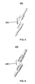
FIG. 5 , in one implementation, an offsetspring 300 includes a single direction windingcenter section 305. - In another implementation, as shown in
FIG. 6 , an offsetspring 400 includes a full wind on acenter section 405 to eliminate tangling. - In still another implementation, as shown in
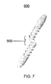
FIG. 7 , an offsetspring 500 includes acenter section 505 that eliminates dual diameters. - Some embodiments may be described using the expression "one embodiment" or "an embodiment" along with their derivatives. These terms mean that a particular feature, structure, or characteristic described in connection with the embodiment is included in at least one embodiment. The appearances of the phrase "in one embodiment" in various places in the specification are not necessarily all referring to the same embodiment.
- While this invention has been particularly shown and described with references to preferred embodiments thereof, it will be understood by those skilled in the art that various changes in form and details may be made therein without departing from the spirit and scope of the present application as defined by the appended claims. Such variations are intended to be covered by the scope of this present application. As such, the foregoing description of embodiments of the present application is not intended to be limiting. Rather, any limitations to the invention are presented in the following claims.
- The present application also discloses the following, set in numbered paragraphs (§):
- §1. A pressure sensor comprising:
- a spring having first and second coiled sections offset by a coiled center section in a middle that is used to make offset contact between two electrical contact pads.
- §2. The pressure sensor of paragraph §1 further comprising:
- first and second housing interlocking components where the first coiled section is contained within a bore of the first housing interlocking component and the second coiled section is contained in a bore of the second housing interlocking component, the first and second housing interlocking components joined at the coiled center section of the spring.
- §3. The pressure sensor of paragraph §1 wherein the offset comprises an approximate offset amount determined by subtracting an active coil diameter of the first and second coiled sections from a diameter of the coiled center section.
- §4. The pressure sensor of paragraph §2 wherein the first housing interlocking component is designed such that a force generated when the spring is compressed is supported in a normal direction by a mating force of the second housing interlocking.
- §5. The pressure sensor of paragraph §2 wherein the bores in the first and second housing interlocking components comprise feed-in features to aid in spring loading and accommodate positional tolerance between the first and second coiled sections.
- §6. The pressure sensor of paragraph §2 wherein the bore in the first housing interlocking component comprises a counterbored feature to accept the center coiled section to rotationally align the spring prior to installation of the second interlocking component.
- §7. The pressure sensor of paragraph §6 wherein the first housing interlocking component further comprises a keyed alignment guide with deformable crush ribs regions to accept crush ribs from the second interlocking component to provide positioning and anti-rotation to prevent damage or binding of the spring.
- §8. The pressure sensor of paragraph §2 wherein the first and second housing interlocking components are injection molded plastic.
- §9. The pressure sensor of paragraph §1 wherein the spring is stainless steel.
- §10. The pressure sensor of paragraph §9 wherein the stainless steel in silver plated for high conductivity.
- §11. The pressure sensor of paragraph §7 wherein friction between the crush ribs of first housing interlocking component and a surface of the second housing interlocking component enable the first housing interlocking component and the second housing interlocking component to retain the spring during manufacturing.
- §12. The pressure sensor of paragraph §2 wherein the center section enables spring retention by the first housing interlocking component and the second housing interlocking component.
- §13. The pressure sensor of paragraph §2 further comprising an electronics module assembly adapted to snap fit to the first and second housing interlocking components.
- §14. The pressure sensor of paragraph §13 wherein the electronics module assembly comprises:
- a support ring; and
- a printed circuit board.
- §15. The pressure sensor of paragraph §14 wherein the support ring comprises one or more strain gages coupled to a sense element.
- §16. The pressure sensor of paragraph §1 wherein the center section of the spring is circular.
- §17. The pressure sensor of paragraph §1 wherein the center section of the spring is a single direction winding.
- §18. The pressure sensor of paragraph §1 wherein the center section of the spring is a full wind.
- §19. The pressure sensor of paragraph §1 wherein the center section of the spring is designed to eliminate dual diameters.
- §20. The pressure sensor of paragraph §13 further comprising an EMC shield positioned between the electronics module assembly and the first and second housing interlocking components, the EMC shield grounded by bent metal features.
Claims (14)
- A pressure sensor comprising:a spring having first and second coiled sections offset by a coiled center section in a middle that is used to make offset contact between two electrical contact pads.
- The pressure sensor of claim 1 further comprising:first and second housing interlocking components where the first coiled section is contained within a bore of the first housing interlocking component and the second coiled section is contained in a bore of the second housing interlocking component, the first and second housing interlocking components joined at the coiled center section of the spring.
- The pressure sensor of claim 1 wherein the offset comprises an approximate offset amount determined by subtracting an active coil diameter of the first and second coiled sections from a diameter of the coiled center section.
- The pressure sensor of claim 2 wherein the first housing interlocking component is designed such that a force generated when the spring is compressed is supported in a normal direction by a mating force of the second housing interlocking.
- The pressure sensor of claim 2 wherein the bores in the first and second housing interlocking components comprise feed-in features to aid in spring loading and accommodate positional tolerance between the first and second coiled sections.
- The pressure sensor of claim 2 wherein the bore in the first housing interlocking component comprises a counterbored feature to accept the center coiled section to rotationally align the spring prior to installation of the second interlocking component.
- The pressure sensor of claim 6 wherein the first housing interlocking component further comprises a keyed alignment guide with deformable crush ribs regions to accept crush ribs from the second interlocking component to provide positioning and anti-rotation to prevent damage or binding of the spring.
- The pressure sensor of claim 2 wherein the first and second housing interlocking components are injection molded plastic.
- The pressure sensor of claim 7 wherein friction between the crush ribs of first housing interlocking component and a surface of the second housing interlocking component enable the first housing interlocking component and the second housing interlocking component to retain the spring during manufacturing.
- The pressure sensor of claim 2 wherein the center section enables spring retention by the first housing interlocking component and the second housing interlocking component.
- The pressure sensor of claim 2 further comprising an electronics module assembly adapted to snap fit to the first and second housing interlocking components.
- The pressure sensor of claim 1 wherein the center section of the spring is circular, is a single direction winding or a full wind.
- The pressure sensor of claim 1 wherein the center section of the spring is designed to eliminate dual diameters.
- The pressure sensor of claim 11 further comprising an EMC shield positioned between the electronics module assembly and the first and second housing interlocking components, the EMC shield grounded by bent metal features.
Applications Claiming Priority (1)
| Application Number | Priority Date | Filing Date | Title |
|---|---|---|---|
| US14/451,926 US9568388B2 (en) | 2014-08-05 | 2014-08-05 | Small form factor pressure sensor |
Publications (3)
| Publication Number | Publication Date |
|---|---|
| EP2985581A1 true EP2985581A1 (en) | 2016-02-17 |
| EP2985581A8 EP2985581A8 (en) | 2016-03-23 |
| EP2985581B1 EP2985581B1 (en) | 2017-08-23 |
Family
ID=53546171
Family Applications (1)
| Application Number | Title | Priority Date | Filing Date |
|---|---|---|---|
| EP15176872.8A Not-in-force EP2985581B1 (en) | 2014-08-05 | 2015-07-15 | Small form factor pressure sensor |
Country Status (5)
| Country | Link |
|---|---|
| US (1) | US9568388B2 (en) |
| EP (1) | EP2985581B1 (en) |
| JP (1) | JP6363564B2 (en) |
| KR (1) | KR102233872B1 (en) |
| CN (1) | CN105333990B (en) |
Cited By (1)
| Publication number | Priority date | Publication date | Assignee | Title |
|---|---|---|---|---|
| WO2019029971A1 (en) * | 2017-08-09 | 2019-02-14 | Robert Bosch Gmbh | PRESSURE SENSOR FOR MEASURING A PRESSURE OF A FLUID AND METHOD FOR PRODUCING A PRESSURE SENSOR FOR MEASURING A PRESSURE OF A FLUID |
Families Citing this family (7)
| Publication number | Priority date | Publication date | Assignee | Title |
|---|---|---|---|---|
| CN105731204A (en) * | 2016-03-24 | 2016-07-06 | 周玉红 | Stress sensor for vertical elevator |
| JP6780513B2 (en) * | 2017-01-18 | 2020-11-04 | 株式会社オートネットワーク技術研究所 | Terminal module |
| CN109307567B (en) * | 2018-10-25 | 2020-12-11 | 中国科学院合肥物质科学研究院 | A kind of omnidirectional overload protection mechanism and design method |
| CN209326840U (en) | 2018-12-27 | 2019-08-30 | 热敏碟公司 | Pressure sensor and pressure transmitter |
| KR102267037B1 (en) * | 2019-11-29 | 2021-06-21 | 만도헬라일렉트로닉스(주) | Pressure Sensor Assembly |
| CN115979497B (en) * | 2023-01-30 | 2023-10-27 | 深圳安培龙科技股份有限公司 | Small-diameter high-pressure sensor, manufacturing method thereof and sensor diameter reduction method |
| WO2025226278A1 (en) * | 2024-04-26 | 2025-10-30 | Sensata Technologies, Inc. | Connector assembly |
Citations (3)
| Publication number | Priority date | Publication date | Assignee | Title |
|---|---|---|---|---|
| US20040147140A1 (en) * | 2003-01-24 | 2004-07-29 | Zhineng Fan | Low inductance electrical contacts and lga connector system |
| US20110108322A1 (en) * | 2008-07-04 | 2011-05-12 | Harry Kaiser | Pre-installation assembly for a contact arrangement of a sensor assembly |
| EP2390641A2 (en) * | 2010-05-27 | 2011-11-30 | Sensata Technologies, Inc. | Pressure Sensor |
Family Cites Families (17)
| Publication number | Priority date | Publication date | Assignee | Title |
|---|---|---|---|---|
| CA1162243A (en) * | 1979-12-26 | 1984-02-14 | Jonathon H. Katz | Test pin |
| JP3994887B2 (en) * | 2003-03-04 | 2007-10-24 | 株式会社デンソー | Pressure sensor |
| US7626408B1 (en) * | 2005-02-03 | 2009-12-01 | KK Technologies, Inc. | Electrical spring probe |
| JP2006258471A (en) * | 2005-03-15 | 2006-09-28 | Denso Corp | Pressure sensor |
| DE102006056242A1 (en) * | 2006-11-27 | 2008-05-29 | Robert Bosch Gmbh | Pressure sensor for use in brake system of motor vehicle, has connection port running in housing, return valve integrated in housing, another connection port provided for pressure source, and return valve arranged between flow section areas |
| ES2615402T3 (en) * | 2007-03-19 | 2017-06-06 | Boston Scientific Neuromodulation Corporation | IRM and RF compatible cables |
| US7862391B2 (en) * | 2007-09-18 | 2011-01-04 | Delaware Capital Formation, Inc. | Spring contact assembly |
| KR100923202B1 (en) * | 2007-12-05 | 2009-10-22 | 주식회사 만도 | Pressure sensor |
| US20100267291A1 (en) * | 2009-04-20 | 2010-10-21 | Scott Chabineau-Lovgren | Swaging process for improved compliant contact electrical test performance |
| KR101756477B1 (en) * | 2010-12-30 | 2017-07-11 | 타이코에이엠피 주식회사 | Pressure sensor |
| US8735751B2 (en) * | 2011-04-26 | 2014-05-27 | Bal Seal Engineering, Inc. | Varying diameter canted coil spring contacts and related methods of forming |
| US20130192379A1 (en) * | 2012-01-27 | 2013-08-01 | Neil S. Petrarca | Small form factor microfused silicon strain gage (msg) pressure sensor packaging |
| KR20130138433A (en) * | 2012-06-11 | 2013-12-19 | 주식회사 만도 | Structure for excluding water inflow of pressure sensor and electronic brake system having the same |
| KR102000294B1 (en) | 2012-09-28 | 2019-07-15 | 타이코에이엠피 주식회사 | Pressure sensor |
| KR101897293B1 (en) * | 2012-09-28 | 2018-09-11 | 타이코에이엠피 주식회사 | Pressure sensor |
| KR102000293B1 (en) * | 2012-09-28 | 2019-07-15 | 타이코에이엠피 주식회사 | Pressure sensor |
| WO2014117093A1 (en) * | 2013-01-25 | 2014-07-31 | Bal Seal Engineering, Inc. | Coil springs with complex coil configurations, assemblies with coil springs, and related methods |
-
2014
- 2014-08-05 US US14/451,926 patent/US9568388B2/en active Active
-
2015
- 2015-07-15 EP EP15176872.8A patent/EP2985581B1/en not_active Not-in-force
- 2015-07-27 JP JP2015147849A patent/JP6363564B2/en not_active Expired - Fee Related
- 2015-07-30 KR KR1020150107899A patent/KR102233872B1/en not_active Expired - Fee Related
- 2015-08-05 CN CN201510472123.XA patent/CN105333990B/en active Active
Patent Citations (3)
| Publication number | Priority date | Publication date | Assignee | Title |
|---|---|---|---|---|
| US20040147140A1 (en) * | 2003-01-24 | 2004-07-29 | Zhineng Fan | Low inductance electrical contacts and lga connector system |
| US20110108322A1 (en) * | 2008-07-04 | 2011-05-12 | Harry Kaiser | Pre-installation assembly for a contact arrangement of a sensor assembly |
| EP2390641A2 (en) * | 2010-05-27 | 2011-11-30 | Sensata Technologies, Inc. | Pressure Sensor |
Cited By (2)
| Publication number | Priority date | Publication date | Assignee | Title |
|---|---|---|---|---|
| WO2019029971A1 (en) * | 2017-08-09 | 2019-02-14 | Robert Bosch Gmbh | PRESSURE SENSOR FOR MEASURING A PRESSURE OF A FLUID AND METHOD FOR PRODUCING A PRESSURE SENSOR FOR MEASURING A PRESSURE OF A FLUID |
| US11125639B2 (en) | 2017-08-09 | 2021-09-21 | Robert Bosch Gmbh | Pressure sensor for measuring a pressure of a fluid and method for producing a pressure sensor for measuring a pressure of a fluid |
Also Published As
| Publication number | Publication date |
|---|---|
| KR102233872B1 (en) | 2021-03-29 |
| CN105333990B (en) | 2018-09-04 |
| JP6363564B2 (en) | 2018-07-25 |
| KR20160016656A (en) | 2016-02-15 |
| US9568388B2 (en) | 2017-02-14 |
| JP2016038378A (en) | 2016-03-22 |
| EP2985581A8 (en) | 2016-03-23 |
| US20160041055A1 (en) | 2016-02-11 |
| CN105333990A (en) | 2016-02-17 |
| EP2985581B1 (en) | 2017-08-23 |
Similar Documents
| Publication | Publication Date | Title |
|---|---|---|
| US9568388B2 (en) | Small form factor pressure sensor | |
| US9435827B2 (en) | Probe-connection-type pogo pin and manufacturing method thereof | |
| US9391390B2 (en) | Spring connector with waterproofing function | |
| US8708716B1 (en) | Electrical connector | |
| KR101894965B1 (en) | Probe pin and ic socket | |
| US10468804B2 (en) | Connector terminal assembly | |
| EP1981129A2 (en) | Coaxial Connector | |
| CN105098467B (en) | Water proof type card connector | |
| EP2846415B1 (en) | Stepped spring contact | |
| WO2013100064A1 (en) | Electrical contact and electrical part socket | |
| EP2472234A3 (en) | Sensing assembly components and methods of assembling, mounting and orientating same | |
| US8159249B2 (en) | Inspection unit | |
| KR101183809B1 (en) | Coaxial connector for inspection | |
| US8167664B2 (en) | Receptacle connector | |
| US12278524B2 (en) | Temperature sensor and rotary electric machine | |
| CN112585836B (en) | Charging device | |
| WO2014112012A1 (en) | Liquid level detecting module | |
| US9502788B2 (en) | Connector assembly with a conductor assembly partially disposed in a block assembly | |
| US10770819B2 (en) | Connector | |
| CN109755832B (en) | Vibration absorber for slip ring brush | |
| JP2014035322A (en) | Core holder and current sensor | |
| US20140230545A1 (en) | Sensor and method of making a sensor | |
| JP2014143889A (en) | Grommet | |
| US8674801B2 (en) | Induction component | |
| US20110275227A1 (en) | Module to circuit board connector |
Legal Events
| Date | Code | Title | Description |
|---|---|---|---|
| PUAI | Public reference made under article 153(3) epc to a published international application that has entered the european phase |
Free format text: ORIGINAL CODE: 0009012 |
|
| AK | Designated contracting states |
Kind code of ref document: A1 Designated state(s): AL AT BE BG CH CY CZ DE DK EE ES FI FR GB GR HR HU IE IS IT LI LT LU LV MC MK MT NL NO PL PT RO RS SE SI SK SM TR |
|
| AX | Request for extension of the european patent |
Extension state: BA ME |
|
| RAP1 | Party data changed (applicant data changed or rights of an application transferred) |
Owner name: SENSATA TECHNOLOGIES, INC. |
|
| 17P | Request for examination filed |
Effective date: 20160802 |
|
| RBV | Designated contracting states (corrected) |
Designated state(s): AL AT BE BG CH CY CZ DE DK EE ES FI FR GB GR HR HU IE IS IT LI LT LU LV MC MK MT NL NO PL PT RO RS SE SI SK SM TR |
|
| 17Q | First examination report despatched |
Effective date: 20160823 |
|
| STAA | Information on the status of an ep patent application or granted ep patent |
Free format text: STATUS: EXAMINATION IS IN PROGRESS |
|
| GRAP | Despatch of communication of intention to grant a patent |
Free format text: ORIGINAL CODE: EPIDOSNIGR1 |
|
| STAA | Information on the status of an ep patent application or granted ep patent |
Free format text: STATUS: GRANT OF PATENT IS INTENDED |
|
| INTG | Intention to grant announced |
Effective date: 20170222 |
|
| GRAS | Grant fee paid |
Free format text: ORIGINAL CODE: EPIDOSNIGR3 |
|
| GRAA | (expected) grant |
Free format text: ORIGINAL CODE: 0009210 |
|
| STAA | Information on the status of an ep patent application or granted ep patent |
Free format text: STATUS: THE PATENT HAS BEEN GRANTED |
|
| AK | Designated contracting states |
Kind code of ref document: B1 Designated state(s): AL AT BE BG CH CY CZ DE DK EE ES FI FR GB GR HR HU IE IS IT LI LT LU LV MC MK MT NL NO PL PT RO RS SE SI SK SM TR |
|
| REG | Reference to a national code |
Ref country code: GB Ref legal event code: FG4D |
|
| REG | Reference to a national code |
Ref country code: CH Ref legal event code: EP |
|
| REG | Reference to a national code |
Ref country code: AT Ref legal event code: REF Ref document number: 921854 Country of ref document: AT Kind code of ref document: T Effective date: 20170915 |
|
| REG | Reference to a national code |
Ref country code: IE Ref legal event code: FG4D |
|
| REG | Reference to a national code |
Ref country code: DE Ref legal event code: R096 Ref document number: 602015004251 Country of ref document: DE |
|
| REG | Reference to a national code |
Ref country code: NL Ref legal event code: MP Effective date: 20170823 |
|
| REG | Reference to a national code |
Ref country code: LT Ref legal event code: MG4D |
|
| REG | Reference to a national code |
Ref country code: AT Ref legal event code: MK05 Ref document number: 921854 Country of ref document: AT Kind code of ref document: T Effective date: 20170823 |
|
| PG25 | Lapsed in a contracting state [announced via postgrant information from national office to epo] |
Ref country code: LT Free format text: LAPSE BECAUSE OF FAILURE TO SUBMIT A TRANSLATION OF THE DESCRIPTION OR TO PAY THE FEE WITHIN THE PRESCRIBED TIME-LIMIT Effective date: 20170823 Ref country code: FI Free format text: LAPSE BECAUSE OF FAILURE TO SUBMIT A TRANSLATION OF THE DESCRIPTION OR TO PAY THE FEE WITHIN THE PRESCRIBED TIME-LIMIT Effective date: 20170823 Ref country code: SE Free format text: LAPSE BECAUSE OF FAILURE TO SUBMIT A TRANSLATION OF THE DESCRIPTION OR TO PAY THE FEE WITHIN THE PRESCRIBED TIME-LIMIT Effective date: 20170823 Ref country code: NL Free format text: LAPSE BECAUSE OF FAILURE TO SUBMIT A TRANSLATION OF THE DESCRIPTION OR TO PAY THE FEE WITHIN THE PRESCRIBED TIME-LIMIT Effective date: 20170823 Ref country code: NO Free format text: LAPSE BECAUSE OF FAILURE TO SUBMIT A TRANSLATION OF THE DESCRIPTION OR TO PAY THE FEE WITHIN THE PRESCRIBED TIME-LIMIT Effective date: 20171123 Ref country code: AT Free format text: LAPSE BECAUSE OF FAILURE TO SUBMIT A TRANSLATION OF THE DESCRIPTION OR TO PAY THE FEE WITHIN THE PRESCRIBED TIME-LIMIT Effective date: 20170823 Ref country code: HR Free format text: LAPSE BECAUSE OF FAILURE TO SUBMIT A TRANSLATION OF THE DESCRIPTION OR TO PAY THE FEE WITHIN THE PRESCRIBED TIME-LIMIT Effective date: 20170823 |
|
| PG25 | Lapsed in a contracting state [announced via postgrant information from national office to epo] |
Ref country code: PL Free format text: LAPSE BECAUSE OF FAILURE TO SUBMIT A TRANSLATION OF THE DESCRIPTION OR TO PAY THE FEE WITHIN THE PRESCRIBED TIME-LIMIT Effective date: 20170823 Ref country code: LV Free format text: LAPSE BECAUSE OF FAILURE TO SUBMIT A TRANSLATION OF THE DESCRIPTION OR TO PAY THE FEE WITHIN THE PRESCRIBED TIME-LIMIT Effective date: 20170823 Ref country code: ES Free format text: LAPSE BECAUSE OF FAILURE TO SUBMIT A TRANSLATION OF THE DESCRIPTION OR TO PAY THE FEE WITHIN THE PRESCRIBED TIME-LIMIT Effective date: 20170823 Ref country code: RS Free format text: LAPSE BECAUSE OF FAILURE TO SUBMIT A TRANSLATION OF THE DESCRIPTION OR TO PAY THE FEE WITHIN THE PRESCRIBED TIME-LIMIT Effective date: 20170823 Ref country code: IS Free format text: LAPSE BECAUSE OF FAILURE TO SUBMIT A TRANSLATION OF THE DESCRIPTION OR TO PAY THE FEE WITHIN THE PRESCRIBED TIME-LIMIT Effective date: 20171223 Ref country code: GR Free format text: LAPSE BECAUSE OF FAILURE TO SUBMIT A TRANSLATION OF THE DESCRIPTION OR TO PAY THE FEE WITHIN THE PRESCRIBED TIME-LIMIT Effective date: 20171124 Ref country code: BG Free format text: LAPSE BECAUSE OF FAILURE TO SUBMIT A TRANSLATION OF THE DESCRIPTION OR TO PAY THE FEE WITHIN THE PRESCRIBED TIME-LIMIT Effective date: 20171123 |
|
| PG25 | Lapsed in a contracting state [announced via postgrant information from national office to epo] |
Ref country code: CZ Free format text: LAPSE BECAUSE OF FAILURE TO SUBMIT A TRANSLATION OF THE DESCRIPTION OR TO PAY THE FEE WITHIN THE PRESCRIBED TIME-LIMIT Effective date: 20170823 Ref country code: DK Free format text: LAPSE BECAUSE OF FAILURE TO SUBMIT A TRANSLATION OF THE DESCRIPTION OR TO PAY THE FEE WITHIN THE PRESCRIBED TIME-LIMIT Effective date: 20170823 Ref country code: RO Free format text: LAPSE BECAUSE OF FAILURE TO SUBMIT A TRANSLATION OF THE DESCRIPTION OR TO PAY THE FEE WITHIN THE PRESCRIBED TIME-LIMIT Effective date: 20170823 |
|
| REG | Reference to a national code |
Ref country code: DE Ref legal event code: R097 Ref document number: 602015004251 Country of ref document: DE |
|
| PG25 | Lapsed in a contracting state [announced via postgrant information from national office to epo] |
Ref country code: EE Free format text: LAPSE BECAUSE OF FAILURE TO SUBMIT A TRANSLATION OF THE DESCRIPTION OR TO PAY THE FEE WITHIN THE PRESCRIBED TIME-LIMIT Effective date: 20170823 Ref country code: SM Free format text: LAPSE BECAUSE OF FAILURE TO SUBMIT A TRANSLATION OF THE DESCRIPTION OR TO PAY THE FEE WITHIN THE PRESCRIBED TIME-LIMIT Effective date: 20170823 Ref country code: IT Free format text: LAPSE BECAUSE OF FAILURE TO SUBMIT A TRANSLATION OF THE DESCRIPTION OR TO PAY THE FEE WITHIN THE PRESCRIBED TIME-LIMIT Effective date: 20170823 Ref country code: SK Free format text: LAPSE BECAUSE OF FAILURE TO SUBMIT A TRANSLATION OF THE DESCRIPTION OR TO PAY THE FEE WITHIN THE PRESCRIBED TIME-LIMIT Effective date: 20170823 |
|
| PLBE | No opposition filed within time limit |
Free format text: ORIGINAL CODE: 0009261 |
|
| STAA | Information on the status of an ep patent application or granted ep patent |
Free format text: STATUS: NO OPPOSITION FILED WITHIN TIME LIMIT |
|
| 26N | No opposition filed |
Effective date: 20180524 |
|
| PG25 | Lapsed in a contracting state [announced via postgrant information from national office to epo] |
Ref country code: SI Free format text: LAPSE BECAUSE OF FAILURE TO SUBMIT A TRANSLATION OF THE DESCRIPTION OR TO PAY THE FEE WITHIN THE PRESCRIBED TIME-LIMIT Effective date: 20170823 |
|
| REG | Reference to a national code |
Ref country code: CH Ref legal event code: PL |
|
| PG25 | Lapsed in a contracting state [announced via postgrant information from national office to epo] |
Ref country code: LU Free format text: LAPSE BECAUSE OF NON-PAYMENT OF DUE FEES Effective date: 20180715 Ref country code: MC Free format text: LAPSE BECAUSE OF FAILURE TO SUBMIT A TRANSLATION OF THE DESCRIPTION OR TO PAY THE FEE WITHIN THE PRESCRIBED TIME-LIMIT Effective date: 20170823 |
|
| REG | Reference to a national code |
Ref country code: BE Ref legal event code: MM Effective date: 20180731 |
|
| REG | Reference to a national code |
Ref country code: IE Ref legal event code: MM4A |
|
| PG25 | Lapsed in a contracting state [announced via postgrant information from national office to epo] |
Ref country code: FR Free format text: LAPSE BECAUSE OF NON-PAYMENT OF DUE FEES Effective date: 20180731 Ref country code: CH Free format text: LAPSE BECAUSE OF NON-PAYMENT OF DUE FEES Effective date: 20180731 Ref country code: LI Free format text: LAPSE BECAUSE OF NON-PAYMENT OF DUE FEES Effective date: 20180731 Ref country code: IE Free format text: LAPSE BECAUSE OF NON-PAYMENT OF DUE FEES Effective date: 20180715 |
|
| PG25 | Lapsed in a contracting state [announced via postgrant information from national office to epo] |
Ref country code: BE Free format text: LAPSE BECAUSE OF NON-PAYMENT OF DUE FEES Effective date: 20180731 |
|
| PG25 | Lapsed in a contracting state [announced via postgrant information from national office to epo] |
Ref country code: MT Free format text: LAPSE BECAUSE OF NON-PAYMENT OF DUE FEES Effective date: 20180715 |
|
| PG25 | Lapsed in a contracting state [announced via postgrant information from national office to epo] |
Ref country code: TR Free format text: LAPSE BECAUSE OF FAILURE TO SUBMIT A TRANSLATION OF THE DESCRIPTION OR TO PAY THE FEE WITHIN THE PRESCRIBED TIME-LIMIT Effective date: 20170823 |
|
| PG25 | Lapsed in a contracting state [announced via postgrant information from national office to epo] |
Ref country code: PT Free format text: LAPSE BECAUSE OF FAILURE TO SUBMIT A TRANSLATION OF THE DESCRIPTION OR TO PAY THE FEE WITHIN THE PRESCRIBED TIME-LIMIT Effective date: 20170823 |
|
| PG25 | Lapsed in a contracting state [announced via postgrant information from national office to epo] |
Ref country code: CY Free format text: LAPSE BECAUSE OF FAILURE TO SUBMIT A TRANSLATION OF THE DESCRIPTION OR TO PAY THE FEE WITHIN THE PRESCRIBED TIME-LIMIT Effective date: 20170823 Ref country code: MK Free format text: LAPSE BECAUSE OF NON-PAYMENT OF DUE FEES Effective date: 20170823 Ref country code: HU Free format text: LAPSE BECAUSE OF FAILURE TO SUBMIT A TRANSLATION OF THE DESCRIPTION OR TO PAY THE FEE WITHIN THE PRESCRIBED TIME-LIMIT; INVALID AB INITIO Effective date: 20150715 |
|
| PG25 | Lapsed in a contracting state [announced via postgrant information from national office to epo] |
Ref country code: AL Free format text: LAPSE BECAUSE OF FAILURE TO SUBMIT A TRANSLATION OF THE DESCRIPTION OR TO PAY THE FEE WITHIN THE PRESCRIBED TIME-LIMIT Effective date: 20170823 |
|
| PGFP | Annual fee paid to national office [announced via postgrant information from national office to epo] |
Ref country code: GB Payment date: 20210727 Year of fee payment: 7 Ref country code: DE Payment date: 20210728 Year of fee payment: 7 |
|
| REG | Reference to a national code |
Ref country code: DE Ref legal event code: R119 Ref document number: 602015004251 Country of ref document: DE |
|
| GBPC | Gb: european patent ceased through non-payment of renewal fee |
Effective date: 20220715 |
|
| PG25 | Lapsed in a contracting state [announced via postgrant information from national office to epo] |
Ref country code: GB Free format text: LAPSE BECAUSE OF NON-PAYMENT OF DUE FEES Effective date: 20220715 Ref country code: DE Free format text: LAPSE BECAUSE OF NON-PAYMENT OF DUE FEES Effective date: 20230201 |