EP2985501A1 - Marine hose line and marine hose - Google Patents
Marine hose line and marine hose Download PDFInfo
- Publication number
- EP2985501A1 EP2985501A1 EP14782542.6A EP14782542A EP2985501A1 EP 2985501 A1 EP2985501 A1 EP 2985501A1 EP 14782542 A EP14782542 A EP 14782542A EP 2985501 A1 EP2985501 A1 EP 2985501A1
- Authority
- EP
- European Patent Office
- Prior art keywords
- marine hose
- sinking
- hose line
- end portion
- resisting
- Prior art date
- Legal status (The legal status is an assumption and is not a legal conclusion. Google has not performed a legal analysis and makes no representation as to the accuracy of the status listed.)
- Withdrawn
Links
- XLYOFNOQVPJJNP-UHFFFAOYSA-N water Substances O XLYOFNOQVPJJNP-UHFFFAOYSA-N 0.000 claims abstract description 46
- 230000008878 coupling Effects 0.000 claims abstract description 26
- 238000010168 coupling process Methods 0.000 claims abstract description 26
- 238000005859 coupling reaction Methods 0.000 claims abstract description 26
- 230000001133 acceleration Effects 0.000 claims description 14
- 239000000463 material Substances 0.000 description 14
- 210000002445 nipple Anatomy 0.000 description 9
- 230000003014 reinforcing effect Effects 0.000 description 7
- 230000000694 effects Effects 0.000 description 3
- 239000012530 fluid Substances 0.000 description 3
- 229910000831 Steel Inorganic materials 0.000 description 2
- 238000004519 manufacturing process Methods 0.000 description 2
- 239000010959 steel Substances 0.000 description 2
- 238000004804 winding Methods 0.000 description 2
- NLHHRLWOUZZQLW-UHFFFAOYSA-N Acrylonitrile Chemical compound C=CC#N NLHHRLWOUZZQLW-UHFFFAOYSA-N 0.000 description 1
- 239000000853 adhesive Substances 0.000 description 1
- 230000001070 adhesive effect Effects 0.000 description 1
- 239000010779 crude oil Substances 0.000 description 1
- 239000000835 fiber Substances 0.000 description 1
- 239000012528 membrane Substances 0.000 description 1
- 239000002184 metal Substances 0.000 description 1
- 239000003921 oil Substances 0.000 description 1
- 229920005989 resin Polymers 0.000 description 1
- 239000011347 resin Substances 0.000 description 1
- 229920003002 synthetic resin Polymers 0.000 description 1
- 239000000057 synthetic resin Substances 0.000 description 1
Images


Classifications
-
- B—PERFORMING OPERATIONS; TRANSPORTING
- B63—SHIPS OR OTHER WATERBORNE VESSELS; RELATED EQUIPMENT
- B63B—SHIPS OR OTHER WATERBORNE VESSELS; EQUIPMENT FOR SHIPPING
- B63B27/00—Arrangement of ship-based loading or unloading equipment for cargo or passengers
- B63B27/24—Arrangement of ship-based loading or unloading equipment for cargo or passengers of pipe-lines
-
- F—MECHANICAL ENGINEERING; LIGHTING; HEATING; WEAPONS; BLASTING
- F16—ENGINEERING ELEMENTS AND UNITS; GENERAL MEASURES FOR PRODUCING AND MAINTAINING EFFECTIVE FUNCTIONING OF MACHINES OR INSTALLATIONS; THERMAL INSULATION IN GENERAL
- F16L—PIPES; JOINTS OR FITTINGS FOR PIPES; SUPPORTS FOR PIPES, CABLES OR PROTECTIVE TUBING; MEANS FOR THERMAL INSULATION IN GENERAL
- F16L1/00—Laying or reclaiming pipes; Repairing or joining pipes on or under water
- F16L1/12—Laying or reclaiming pipes on or under water
- F16L1/20—Accessories therefor, e.g. floats or weights
- F16L1/24—Floats; Weights
-
- F—MECHANICAL ENGINEERING; LIGHTING; HEATING; WEAPONS; BLASTING
- F16—ENGINEERING ELEMENTS AND UNITS; GENERAL MEASURES FOR PRODUCING AND MAINTAINING EFFECTIVE FUNCTIONING OF MACHINES OR INSTALLATIONS; THERMAL INSULATION IN GENERAL
- F16L—PIPES; JOINTS OR FITTINGS FOR PIPES; SUPPORTS FOR PIPES, CABLES OR PROTECTIVE TUBING; MEANS FOR THERMAL INSULATION IN GENERAL
- F16L11/00—Hoses, i.e. flexible pipes
- F16L11/04—Hoses, i.e. flexible pipes made of rubber or flexible plastics
- F16L11/12—Hoses, i.e. flexible pipes made of rubber or flexible plastics with arrangements for particular purposes, e.g. specially profiled, with protecting layer, heated, electrically conducting
- F16L11/133—Hoses, i.e. flexible pipes made of rubber or flexible plastics with arrangements for particular purposes, e.g. specially profiled, with protecting layer, heated, electrically conducting buoyant
Definitions
- the present invention relates to a marine hose line and marine hose; and particularly relates to a marine hose line and a marine hose that avoid increasing the diameter and reducing the flexibility of the hose body portion, and is capable of preventing the marine hose line from sinking to a water bottom, even if an end portion of the marine hose line let out onto water from a take-up reel is cut off from a coupling and falls to the surface of the water.
- Floating-type marine hoses equipped with a buoyant layer made of a sponge or other buoyancy material serve as marine hoses connected between a tanker at sea and onshore facilities for transporting crude oil and the like. Multiple connected marine hoses form a marine hose line. Marine hose lines are stored wound around take-up reels installed on tankers and floating production, storage and offloading systems (FPSO) (See Patent Document 1, for example). During use, marine hose lines wound up around a take-up reel are let out from the take-up reel and extended onto water.
- FPSO floating production, storage and offloading systems
- marine hose lines are cut off from the coupling at the end portion on the take-up reel side, while still let out from the take-up reel and extending onto water.
- the marine hoses have considerable weight, and the take-up reels are disposed at positions of considerable height above the surface of water.
- the end portion of marine hose lines cut off from coupling sinks to a position deep below the surface of the water.
- the buoyant layer of a marine hose is formed of sponge or other deformable buoyancy material.
- the buoyancy material is crushed and buoyancy is lost.
- the end portion of the marine hose line sinks further and the buoyancy material is further crushed.
- the extent of crushing of the buoyancy material is then magnified and further buoyancy is lost.
- auto-submersion occurs when the end portion of the marine hose line sinks to a certain depth of water, there is no buoyancy left to float the end portion of the marine hose line; in other words, auto-submersion occurs.
- the marine hose line sinks to the water bottom.
- the measures taken to prevent such marine hose lines from sinking are to use a buoyancy material that does not easily deform from water pressure for the marine hose constituting the end portion on the take-up reel side, and to provide a larger quantity of buoyancy material from the start.
- these measures result in loss of flexibility in the marine hose, which makes it unsuitable for winding up around the take-up reel.
- the problem is that the outer diameter of the hose body portion is enlarged, resulting in an excessively large wind-up outer diameter when it is wound around the take-up reel.
- Patent Document 1 Japanese Unexamined Patent Application Publication No. 2008-215483A
- An object of the present invention is to provide a marine hose line and a marine hose that avoid increasing the diameter and reducing the flexibility of the hose body portion, and is capable of preventing the marine hose line from sinking to a water bottom, even if an end portion of the marine hose line let out onto water from a take-up reel is cut off from a coupling and falls to the surface of the water.
- a marine hose line of the present invention is a marine hose line let out from a take-up reel and extended onto water, the marine hose line comprising a sinking-resisting device installed on an end portion of the marine hose line on the take-up reel side.
- the sinking-resisting device includes a sinking-resisting body installed on the outer surface of the marine hose line in a folded-up state and an expander that expands the folded-up sinking-resisting body.
- the expander is activated to expand the folded-up sinking-resisting body, and the drag from the expanded sinking-resisting body in the water prevents the end portion of the marine hose line from sinking.
- a marine hose of the present invention is a marine hose constituting an end portion on the take-up reel side of a marine hose line, the marine hose comprising a sinking-resisting device including a sinking-resisting body installed on the outer surface of a marine hose in a folded-up state, and an expander that expands the folded-up sinking-resisting body.
- the expander is activated to expand the folded-up sinking-resisting body, and the drag from the expanded sinking-resisting body in the water prevents the end portion of the marine hose line from sinking.
- a marine hose line of the present invention by using a sinking-resisting device including a sinking-resisting body installed in a folded-up state on the outer surface of a marine hose line, and an expander that expands the folded-up sinking-resisting body, it is possible to avoid increasing the diameter and reducing the flexibility of the hose body portion. Therefore, after the end portion of the marine hose line is cut off from a coupling, the expander is activated to expand the folded-up sinking-resisting body, and the drag from the expanded sinking-resisting body in the water prevents the end portion of the marine hose line from sinking. Thus, it is possible to prevent the end portion of the marine hose line on the take-up reel side from sinking to a water bottom, even if it falls to the surface of the water from a high position.
- a marine hose line is connected to the position constituting the end portion of the marine hose line, it is possible to achieve the above effects with a marine hose line of the present invention.
- a marine hose line L of the present invention is formed by connecting a plurality of marine hoses 1, 1A, and is let out from a take-up reel 14 and extended onto water.
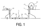
- the marine hose line L is formed between an FPSO 16 and a tanker 17.
- a take-up reel 14 is installed on the FPSO 16, and the marine hoses 1, 1A forming the marine hose line L are let out and extended onto water.
- a marine hose 1 of the present invention constitutes the end portion of the marine hose line L on the take-up reel 14 side, and has a configuration different from that of the other marine hose 1A.
- the marine hose line L is equipped with a sinking-resisting device 8 installed on the end portion on the take-up reel 14 side.
- a marine hose 1 of the present invention is equipped with a sinking-resisting device 8.
- the marine hose 1 is equipped with connection fittings 2 on both longitudinal ends with a coupling 15 installed on one end side. One longitudinal end of the marine hose 1 is connected to a coupling 15 installed on the take-up reel 14 via the coupling 15.
- the connection fittings 2 are constituted by nipples 2b equipped with a flange 2a on one end.
- the marine hoses 1, 1A are connected by a pair of connection fittings 2.
- An inner surface rubber layer 3, a main reinforcing layer 4 and a main body wire layer 5 are layered in that order winding around the outer circumference of the nipples 2b towards the outer circumferential side, and the outermost circumference is covered with a cover rubber layer 7.
- the inner circumferential side of the inner surface rubber layer 3 serves as a fluid flow path 1a.
- the chain dotted line CL in FIG. 3 is a center line that extends in the axial direction of the marine hose 1.
- a buoyant layer 6 formed of sponge or other buoyancy material is provided between the layers of the main body wire layer 5 and the cover rubber layer 7. That is, the present invention may be used for a floating-type marine hose 1.
- the inner surface rubber layer 3 that makes contact with fluid being transported is constituted by an acrylonitrile rubber with good oil resistance or the like, and the main body wire layer 5 is constituted by a metal wire wound spirally with predetermined spacing on the rubber layer on the outer circumference of the main reinforcing layer 4.
- the main reinforcing layer 4 is constituted by layering a plurality of reinforcing cord layers made by covering reinforcing cord with rubber.
- Nipple wires 4a, 5a on one end portion of the main reinforcing layer 4 and main body wire layer 5 respectively are fixed to the nipple 2b by a fixing ring 2c or the like protruding from the outer circumferential surface of the nipple 2b.
- the cover rubber layer 7 is constituted by rubber or other non-water-permeable material, with a highly visible line pattern or the like on the surface.
- the marine hose 1 is not limited to the configuration illustrated in FIG. 3 .
- the sinking-resisting device 8 is installed, for example, on the outer circumferential side or flange 2a of the nipple 2b of a connection fitting 2, or on the hose body portion (at a section other than the connection fitting 2).
- the number of sinking-resisting devices 8 installed on a marine hose 1 is not particularly limited, and may be singular or plural.
- the sinking-resisting device 8 has a sinking-resisting body 10 installed in a compact folded-up state on the outer surface of the marine hose line L, and an expander 11 that expands the folded-up sinking-resisting body 10.
- a drag chute formed of a strong synthetic resin fiber membrane, for example, may be used as the sinking-resisting body 10.
- the expander 11 is equipped with a gas cylinder for storing pressurized air and a nozzle for injecting pressurized air.
- the sinking-resisting device 8 also has a sensor 9 that activates the expander 11.
- An acceleration sensor or a cut-off sensor that detects when a coupling 15 is cut off, for example, may be used for the sensor 9. If an acceleration sensor is used, the expander 11 is activated when the sensor 9 detects a preset acceleration (impact). If a cut-off sensor is used, the expander 11 is activated when it detects that the end portion of the marine hose line L is cut off from the coupling 15.
- the folded-up sinking-resisting body 10 is installed on the outer surface of a marine hose 1 (connection fitting 2 or hose body portion) using a fitting 12 such as a tightening belt.
- the sensor 9 and expander 11 are housed in a waterproof case, and are installed on the outer surface of a marine hose 1, using the fitting 12 such as a tightening belt, bolts, or adhesive.
- the sinking-resisting body 10 is connected to a marine hose 1 with a cord 13.
- a steel cord rope, steel chain, resin rope or the like may be used for the cord 13.
- the marine hose line L is cut off from a coupling 15 at the end portion on the take-up reel 14 side, while still let out from the take-up reel 14 and extending onto water.
- the marine hose 1 has considerable weight, and the take-up reel 14 is disposed at a position of considerable height above the surface of water. Hence, the end portion of a marine hose line L cut off from a coupling 15 will sink to a position deep below the surface of the water.
- the buoyant layer 6 of the marine hoses 1, 1A is formed of sponge or other deformable buoyancy material.
- the buoyancy material is crushed and buoyancy is lost.
- the end portion of the marine hose line L sinks further and the buoyancy material is further crushed.
- the extent of crushing of the buoyancy material is then magnified and further buoyancy is lost. Consequently, when the end portion of the marine hose line L sinks to a certain depth of water, auto-submersion occurs, and the marine hose line L links to the water bottom.
- the expander 11 is then activated to expand the folded-up sinking-resisting body 10.
- the sensor 9 detects acceleration (impact) when the end portion of the marine hose line L falls to the surface of the water, and when this acceleration is detected, the sensor 9 activates the expander 11, and expands the folded-up sinking-resisting body 10 by injecting compressed air from the gas cylinder.
- the sinking-resisting body 10 expands, for example, the fitting 12 fixing the folded-up sinking-resisting body 10 to the marine hose 1 is disconnected by the expanding force.
- the sensor 9 is preset so that the expander 11 is activated when acceleration is detected equal to the acceleration generated when the end portion of the marine hose line L falls to the surface of the water.
- a cut-off sensor is used for the sensor 9, when the end portion of the marine hose line L is cut off from the coupling 15 of the take-up reel 14, the sensor 9 activates the expander 11, and expands the folded-up sinking-resisting body 10 by injecting compressed air from the gas cylinder.
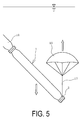
- the expanded sinking-resisting body 10 When a drag chute is used for the sinking-resisting body 10, as illustrated in FIG. 5 , the expanded sinking-resisting body 10 is connected to a marine hose 1 via the cord 13.
- sinking of the end portion of the marine hose line L is prevented by the drag from the expanded sinking-resisting body 10 in the water. That is, before auto-submersion occurs, any further sinking is prevented by the expanded sinking-resisting body 10, making it possible to prevent the marine hose line L from sinking to the water bottom. Accordingly, it is possible to prevent the marine hose line L from sinking to a water bottom, even if the end portion of the marine hose line L on the take-up reel 14 side falls to the surface of the water from a high position.
- the expanded (inflated) sinking-resisting body 10 is connected to a marine hose 1 via the cord 13.
- the sinking-resisting body 10 generates buoyancy, and this buoyancy is conferred to the end portion of the marine hose line L. In this manner, before auto-submersion occurs, any further sinking is prevented by the expanded sinking-resisting body 10, making it possible to prevent the marine hose line L from sinking to the water bottom.
- the sinking-resisting device 8 used in the present invention comprises a folded-up sinking-resisting body 10,and an expander 11 that expands the sinking-resisting body 10, and thus provides a compact non-bulky configuration. Therefore, it is possible to avoid increasing the diameter of the hose body portion. As a result, there is no loss in the flexibility of the marine hose 1, and thus it is possible to prevent loss of operability.
- buoyant layer 6 of the marine hose 1 is not required to be of a significant volume in order to prevent occurrence of auto-submersion, so it is also possible to avoid the problem of wasteful crushing of the buoyant layer 6 when the take-up reel 14 is wound up. Furthermore, there is no loss over time in the drag from the sinking-resisting body 10 in the water, as there is with buoyancy of the buoyant layer 6.
- the marine hose 1 of present invention if the marine hose 1 is connected at the position constituting the end portion of the marine hose line L, it is possible to achieve the above effects with a marine hose line L of the present invention.
Landscapes
- Engineering & Computer Science (AREA)
- General Engineering & Computer Science (AREA)
- Mechanical Engineering (AREA)
- Chemical & Material Sciences (AREA)
- Combustion & Propulsion (AREA)
- Ocean & Marine Engineering (AREA)
- Rigid Pipes And Flexible Pipes (AREA)
Abstract
Provided is a marine hose line and a marine hose that avoid increasing the diameter and reducing the flexibility of the hose body portion, and is capable of preventing the marine hose line from sinking to a water bottom, even if an end portion of the marine hose line let out onto water from a take-up reel is cut off from a coupling and falls to the surface of the water.
A sinking-resisting device 8 installed on an end portion on the take-up reel 14 side of the marine hose line L, includes a sinking-resisting body 10 installed on the outer surface of the marine hose line L in a folded-up state, and an expander 11 that expands the folded-up sinking-resisting body 10. After the end portion of the marine hose line L is cut off from the coupling 15, the expander 11 is activated to expand the folded-up sinking-resisting body 10, and the drag from the expanded sinking-resisting body 10 in the water prevents the end portion of the marine hose line L from sinking.
Description
- The present invention relates to a marine hose line and marine hose; and particularly relates to a marine hose line and a marine hose that avoid increasing the diameter and reducing the flexibility of the hose body portion, and is capable of preventing the marine hose line from sinking to a water bottom, even if an end portion of the marine hose line let out onto water from a take-up reel is cut off from a coupling and falls to the surface of the water.
- Floating-type marine hoses equipped with a buoyant layer made of a sponge or other buoyancy material serve as marine hoses connected between a tanker at sea and onshore facilities for transporting crude oil and the like. Multiple connected marine hoses form a marine hose line. Marine hose lines are stored wound around take-up reels installed on tankers and floating production, storage and offloading systems (FPSO) (See
Patent Document 1, for example). During use, marine hose lines wound up around a take-up reel are let out from the take-up reel and extended onto water. - Sometimes during emergency situations, such marine hose lines are cut off from the coupling at the end portion on the take-up reel side, while still let out from the take-up reel and extending onto water. The marine hoses have considerable weight, and the take-up reels are disposed at positions of considerable height above the surface of water. Hence, the end portion of marine hose lines cut off from coupling sinks to a position deep below the surface of the water.
- The buoyant layer of a marine hose is formed of sponge or other deformable buoyancy material. Thus, when the end portion of a marine hose line sinks to a certain depth of water, the buoyancy material is crushed and buoyancy is lost. When buoyancy of the buoyant layer is lost, the end portion of the marine hose line sinks further and the buoyancy material is further crushed. The extent of crushing of the buoyancy material is then magnified and further buoyancy is lost. Thus, when the end portion of the marine hose line sinks to a certain depth of water, there is no buoyancy left to float the end portion of the marine hose line; in other words, auto-submersion occurs. When auto-submersion occurs, the marine hose line sinks to the water bottom.
- The measures taken to prevent such marine hose lines from sinking are to use a buoyancy material that does not easily deform from water pressure for the marine hose constituting the end portion on the take-up reel side, and to provide a larger quantity of buoyancy material from the start. However, these measures result in loss of flexibility in the marine hose, which makes it unsuitable for winding up around the take-up reel. In addition, if a larger quantity of buoyancy material is used, the problem is that the outer diameter of the hose body portion is enlarged, resulting in an excessively large wind-up outer diameter when it is wound around the take-up reel.
- Patent Document 1: Japanese Unexamined Patent Application Publication No.
2008-215483A - An object of the present invention is to provide a marine hose line and a marine hose that avoid increasing the diameter and reducing the flexibility of the hose body portion, and is capable of preventing the marine hose line from sinking to a water bottom, even if an end portion of the marine hose line let out onto water from a take-up reel is cut off from a coupling and falls to the surface of the water.
- In order to achieve the object, a marine hose line of the present invention is a marine hose line let out from a take-up reel and extended onto water, the marine hose line comprising a sinking-resisting device installed on an end portion of the marine hose line on the take-up reel side. The sinking-resisting device includes a sinking-resisting body installed on the outer surface of the marine hose line in a folded-up state and an expander that expands the folded-up sinking-resisting body. After the end portion of the marine hose line is cut off from a coupling, the expander is activated to expand the folded-up sinking-resisting body, and the drag from the expanded sinking-resisting body in the water prevents the end portion of the marine hose line from sinking.
- A marine hose of the present invention is a marine hose constituting an end portion on the take-up reel side of a marine hose line, the marine hose comprising a sinking-resisting device including a sinking-resisting body installed on the outer surface of a marine hose in a folded-up state, and an expander that expands the folded-up sinking-resisting body. After the end portion of the marine hose line is cut off from a coupling, the expander is activated to expand the folded-up sinking-resisting body, and the drag from the expanded sinking-resisting body in the water prevents the end portion of the marine hose line from sinking.
- According to a marine hose line of the present invention, by using a sinking-resisting device including a sinking-resisting body installed in a folded-up state on the outer surface of a marine hose line, and an expander that expands the folded-up sinking-resisting body, it is possible to avoid increasing the diameter and reducing the flexibility of the hose body portion. Therefore, after the end portion of the marine hose line is cut off from a coupling, the expander is activated to expand the folded-up sinking-resisting body, and the drag from the expanded sinking-resisting body in the water prevents the end portion of the marine hose line from sinking. Thus, it is possible to prevent the end portion of the marine hose line on the take-up reel side from sinking to a water bottom, even if it falls to the surface of the water from a high position.
- According to the present invention, if a marine hose line is connected to the position constituting the end portion of the marine hose line, it is possible to achieve the above effects with a marine hose line of the present invention.
-
-
FIG. 1 is an explanatory view illustrating a marine hose line and marine hose of the present invention. -
FIG. 2 is an explanatory view illustrating an end portion on a take-up reel side of the marine hose line inFIG. 1 . -
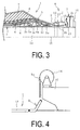
FIG. 3 is a vertical cross-sectional view illustrating the marine hose inFIG. 2 . -
FIG. 4 is an explanatory view illustrating the end portion on the take-up reel side of the marine hose line inFIG. 1 cut off from a coupling. -
FIG. 5 is an explanatory view illustrating an expanded sinking-resisting body. -
FIG. 6 is an explanatory view illustrating a modified example of a sinking-resisting body. - The following is a description of a marine hose line and marine hose of the present invention based on the embodiments illustrated in the drawings.
- As illustrated by
FIGS. 1 to 3 , a marine hose line L of the present invention is formed by connecting a plurality ofmarine hoses up reel 14 and extended onto water. In this embodiment, the marine hose line L is formed between anFPSO 16 and atanker 17. A take-up reel 14 is installed on theFPSO 16, and themarine hoses marine hose 1 of the present invention constitutes the end portion of the marine hose line L on the take-up reel 14 side, and has a configuration different from that of the othermarine hose 1A. - The marine hose line L is equipped with a sinking-resisting
device 8 installed on the end portion on the take-up reel 14 side. In other words, amarine hose 1 of the present invention is equipped with a sinking-resistingdevice 8. - The
marine hose 1 is equipped withconnection fittings 2 on both longitudinal ends with acoupling 15 installed on one end side. One longitudinal end of themarine hose 1 is connected to acoupling 15 installed on the take-up reel 14 via thecoupling 15. Theconnection fittings 2 are constituted by nipples 2b equipped with aflange 2a on one end. Themarine hoses connection fittings 2. - An inner
surface rubber layer 3, a main reinforcinglayer 4 and a mainbody wire layer 5 are layered in that order winding around the outer circumference of thenipples 2b towards the outer circumferential side, and the outermost circumference is covered with acover rubber layer 7. The inner circumferential side of the innersurface rubber layer 3 serves as a fluid flow path 1a. The chain dotted line CL inFIG. 3 is a center line that extends in the axial direction of themarine hose 1. - A
buoyant layer 6 formed of sponge or other buoyancy material is provided between the layers of the mainbody wire layer 5 and thecover rubber layer 7. That is, the present invention may be used for a floating-typemarine hose 1. - The inner
surface rubber layer 3 that makes contact with fluid being transported is constituted by an acrylonitrile rubber with good oil resistance or the like, and the mainbody wire layer 5 is constituted by a metal wire wound spirally with predetermined spacing on the rubber layer on the outer circumference of themain reinforcing layer 4. The main reinforcinglayer 4 is constituted by layering a plurality of reinforcing cord layers made by covering reinforcing cord with rubber. - Nipple
wires layer 4 and mainbody wire layer 5 respectively are fixed to thenipple 2b by afixing ring 2c or the like protruding from the outer circumferential surface of thenipple 2b. Thecover rubber layer 7 is constituted by rubber or other non-water-permeable material, with a highly visible line pattern or the like on the surface. Furthermore, themarine hose 1 is not limited to the configuration illustrated inFIG. 3 . - The sinking-resisting
device 8 is installed, for example, on the outer circumferential side orflange 2a of thenipple 2b of a connection fitting 2, or on the hose body portion (at a section other than the connection fitting 2). The number of sinking-resistingdevices 8 installed on amarine hose 1 is not particularly limited, and may be singular or plural. - As illustrated in
FIG. 3 , the sinking-resistingdevice 8 has a sinking-resistingbody 10 installed in a compact folded-up state on the outer surface of the marine hose line L, and anexpander 11 that expands the folded-up sinking-resistingbody 10. A drag chute formed of a strong synthetic resin fiber membrane, for example, may be used as the sinking-resistingbody 10. Theexpander 11 is equipped with a gas cylinder for storing pressurized air and a nozzle for injecting pressurized air. - The sinking-resisting
device 8 also has a sensor 9 that activates theexpander 11. An acceleration sensor or a cut-off sensor that detects when acoupling 15 is cut off, for example, may be used for the sensor 9. If an acceleration sensor is used, theexpander 11 is activated when the sensor 9 detects a preset acceleration (impact). If a cut-off sensor is used, theexpander 11 is activated when it detects that the end portion of the marine hose line L is cut off from thecoupling 15. - In this embodiment, the folded-up sinking-resisting
body 10 is installed on the outer surface of a marine hose 1 (connection fitting 2 or hose body portion) using a fitting 12 such as a tightening belt. The sensor 9 andexpander 11 are housed in a waterproof case, and are installed on the outer surface of amarine hose 1, using the fitting 12 such as a tightening belt, bolts, or adhesive. - Furthermore, the sinking-resisting
body 10 is connected to amarine hose 1 with acord 13. A steel cord rope, steel chain, resin rope or the like may be used for thecord 13. - As illustrated in
FIG. 4 , sometimes during emergency situations, the marine hose line L is cut off from acoupling 15 at the end portion on the take-up reel 14 side, while still let out from the take-up reel 14 and extending onto water. Themarine hose 1 has considerable weight, and the take-up reel 14 is disposed at a position of considerable height above the surface of water. Hence, the end portion of a marine hose line L cut off from acoupling 15 will sink to a position deep below the surface of the water. - The
buoyant layer 6 of themarine hoses buoyant layer 6 is lost, the end portion of the marine hose line L sinks further and the buoyancy material is further crushed. The extent of crushing of the buoyancy material is then magnified and further buoyancy is lost. Consequently, when the end portion of the marine hose line L sinks to a certain depth of water, auto-submersion occurs, and the marine hose line L links to the water bottom. - However, in the present invention, after the end portion of the marine hose line L is cut off from a
coupling 15, theexpander 11 is then activated to expand the folded-up sinking-resistingbody 10. If, for example, an acceleration sensor is used for the sensor 9, the sensor 9 detects acceleration (impact) when the end portion of the marine hose line L falls to the surface of the water, and when this acceleration is detected, the sensor 9 activates theexpander 11, and expands the folded-up sinking-resistingbody 10 by injecting compressed air from the gas cylinder. When the sinking-resistingbody 10 expands, for example, the fitting 12 fixing the folded-up sinking-resistingbody 10 to themarine hose 1 is disconnected by the expanding force. The sensor 9 is preset so that theexpander 11 is activated when acceleration is detected equal to the acceleration generated when the end portion of the marine hose line L falls to the surface of the water. - If a cut-off sensor is used for the sensor 9, when the end portion of the marine hose line L is cut off from the
coupling 15 of the take-up reel 14, the sensor 9 activates theexpander 11, and expands the folded-up sinking-resistingbody 10 by injecting compressed air from the gas cylinder. - When a drag chute is used for the sinking-resisting
body 10, as illustrated inFIG. 5 , the expanded sinking-resistingbody 10 is connected to amarine hose 1 via thecord 13. Thus, sinking of the end portion of the marine hose line L is prevented by the drag from the expanded sinking-resistingbody 10 in the water. That is, before auto-submersion occurs, any further sinking is prevented by the expanded sinking-resistingbody 10, making it possible to prevent the marine hose line L from sinking to the water bottom. Accordingly, it is possible to prevent the marine hose line L from sinking to a water bottom, even if the end portion of the marine hose line L on the take-up reel 14 side falls to the surface of the water from a high position. - When a floating body filled with compressed air is used as the sinking-resisting
body 10, as illustrated inFIG. 6 , the expanded (inflated) sinking-resistingbody 10 is connected to amarine hose 1 via thecord 13. Thus, sinking of the end portion of the marine hose line L is prevented by the drag from the expanded sinking-resistingbody 10 in the water. Furthermore, the sinking-resistingbody 10 generates buoyancy, and this buoyancy is conferred to the end portion of the marine hose line L. In this manner, before auto-submersion occurs, any further sinking is prevented by the expanded sinking-resistingbody 10, making it possible to prevent the marine hose line L from sinking to the water bottom. - The sinking-resisting
device 8 used in the present invention comprises a folded-up sinking-resistingbody 10,and anexpander 11 that expands the sinking-resistingbody 10, and thus provides a compact non-bulky configuration. Therefore, it is possible to avoid increasing the diameter of the hose body portion. As a result, there is no loss in the flexibility of themarine hose 1, and thus it is possible to prevent loss of operability. - In addition the
buoyant layer 6 of themarine hose 1 is not required to be of a significant volume in order to prevent occurrence of auto-submersion, so it is also possible to avoid the problem of wasteful crushing of thebuoyant layer 6 when the take-up reel 14 is wound up. Furthermore, there is no loss over time in the drag from the sinking-resistingbody 10 in the water, as there is with buoyancy of thebuoyant layer 6. - According to the
marine hose 1 of present invention, if themarine hose 1 is connected at the position constituting the end portion of the marine hose line L, it is possible to achieve the above effects with a marine hose line L of the present invention. -
- 1, 1A Marine hose
- 1a Fluid flow path
- 2 Connection fitting
- 2a Flange
- 2b Nipple
- 2c Fixing ring
- 3 Inner surface rubber layer
- 4 Main reinforcing layer
- 4a Nipple wire
- 5 Main body wire layer
- 5a Nipple wire
- 6 Buoyant layer
- 7 Cover rubber layer
- 8 Sinking-resisting device
- 9 Sensor
- 10 Sinking-resisting body
- 11 Expander
- 12 Fitting
- 13 Cord
- 14 Take-up reel
- 15 Coupling
- 16 FPSO (Floating Production, Storage and Offloading System)
- 17 Tanker
- L Marine hose line
Claims (8)
- A marine hose line let out from a take-up reel and extended onto water, the marine hose line comprising:a sinking-resisting device installed on an end portion of the marine hose line on the take-up reel side,wherein the sinking-resisting device includes a sinking-resisting body installed on the outer surface of the marine hose line in a folded-up state, and an expander that expands the folded-up sinking-resisting body;
after the end portion of the marine hose line is cut off from a coupling, the expander being activated to expand the folded-up sinking-resisting body, and drag from the expanded sinking-resisting body in water preventing the end portion of the marine hose line from sinking. - The marine hose line according to claim 1, wherein
the sinking-resisting device includes an acceleration sensor that activates the expander when the acceleration sensor detects a preset acceleration. - The marine hose line according to claim 1, wherein
the sinking-resisting device includes a coupling cut-off sensor that activates the expander when the cut-off sensor detects that the end portion of the marine hose line is cut off from the coupling. - The marine hose line according to any one of claims 1 to 3, wherein
the expanded sinking-resisting body is a floating body, and generates buoyancy in water. - A marine hose constituting an end portion on a take-up reel side of a marine hose line, the marine hose comprising:a sinking-resisting device includinga sinking-resisting body installed on the outer surface of a marine hose in a folded-up state, andan expander that expands the folded-up sinking-resisting body;after the end portion of the marine hose line is cut off from a coupling, the expander being activated to expand the folded-up sinking-resisting body, and drag from the expanded sinking-resisting body in water preventing the end portion of the marine hose line from sinking.
- The marine hose according to claim 5, wherein
the sinking-resisting device includes an acceleration sensor that activates the expander when the acceleration sensor detects a preset acceleration. - A marine hose according to claim 5, wherein
the sinking-resisting device includes a coupling cut-off sensor that activates the expander when the cut-off sensor detects that the end portion of the marine hose line is cut off from the coupling. - A marine hose according to any one of claims 5 to 7, wherein
the expanded sinking-resisting body is a floating body, and generates buoyancy in water.
Applications Claiming Priority (2)
| Application Number | Priority Date | Filing Date | Title |
|---|---|---|---|
| JP2013080900A JP2014202323A (en) | 2013-04-09 | 2013-04-09 | Marine hose line and marine hose |
| PCT/JP2014/055636 WO2014167921A1 (en) | 2013-04-09 | 2014-03-05 | Marine hose line and marine hose |
Publications (1)
| Publication Number | Publication Date |
|---|---|
| EP2985501A1 true EP2985501A1 (en) | 2016-02-17 |
Family
ID=51689335
Family Applications (1)
| Application Number | Title | Priority Date | Filing Date |
|---|---|---|---|
| EP14782542.6A Withdrawn EP2985501A1 (en) | 2013-04-09 | 2014-03-05 | Marine hose line and marine hose |
Country Status (5)
| Country | Link |
|---|---|
| US (1) | US20160201828A1 (en) |
| EP (1) | EP2985501A1 (en) |
| JP (1) | JP2014202323A (en) |
| BR (1) | BR112015024823A2 (en) |
| WO (1) | WO2014167921A1 (en) |
Families Citing this family (1)
| Publication number | Priority date | Publication date | Assignee | Title |
|---|---|---|---|---|
| JP7853543B2 (en) * | 2021-11-02 | 2026-04-30 | 横浜ゴム株式会社 | Fluid transport hose |
Family Cites Families (4)
| Publication number | Priority date | Publication date | Assignee | Title |
|---|---|---|---|---|
| JP2001018887A (en) * | 1999-07-07 | 2001-01-23 | Bridgestone Corp | Floating hose |
| JP4747834B2 (en) * | 2005-12-27 | 2011-08-17 | 横浜ゴム株式会社 | Marine hose fluid leak detection system |
| JP4174064B2 (en) | 2007-03-02 | 2008-10-29 | 横浜ゴム株式会社 | Marine hose |
| JP4957648B2 (en) * | 2008-05-13 | 2012-06-20 | 横浜ゴム株式会社 | Liquid transport hose |
-
2013
- 2013-04-09 JP JP2013080900A patent/JP2014202323A/en active Pending
-
2014
- 2014-03-05 BR BR112015024823A patent/BR112015024823A2/en not_active IP Right Cessation
- 2014-03-05 EP EP14782542.6A patent/EP2985501A1/en not_active Withdrawn
- 2014-03-05 WO PCT/JP2014/055636 patent/WO2014167921A1/en not_active Ceased
- 2014-03-05 US US14/783,737 patent/US20160201828A1/en not_active Abandoned
Non-Patent Citations (1)
| Title |
|---|
| See references of WO2014167921A1 * |
Also Published As
| Publication number | Publication date |
|---|---|
| US20160201828A1 (en) | 2016-07-14 |
| WO2014167921A1 (en) | 2014-10-16 |
| JP2014202323A (en) | 2014-10-27 |
| BR112015024823A2 (en) | 2017-07-18 |
Similar Documents
| Publication | Publication Date | Title |
|---|---|---|
| US10247337B2 (en) | Hose end construction and fitting | |
| US4509558A (en) | Flexible hose | |
| CN105102722B (en) | Longitudinal type inflating type protective balk | |
| US4153079A (en) | Flexible hose lines | |
| EP2662524B1 (en) | Flexible pipe body with buoyancy element and method of producing same | |
| US9725863B2 (en) | Vertical pneumatic fender and monitoring method for same | |
| EP2843133B1 (en) | Pneumatic fender | |
| EP2161485A2 (en) | Compression resistant floating hose for reeling applications | |
| EP2985502A1 (en) | Marine hose and marine-hose airbag device | |
| EP2985501A1 (en) | Marine hose line and marine hose | |
| JP2021527767A (en) | Underwater mooring line | |
| JP3253399B2 (en) | Conveyance leak detection hose | |
| JP4957648B2 (en) | Liquid transport hose | |
| KR20130143561A (en) | Loading hose | |
| JP4766034B2 (en) | Fluid transfer hose | |
| JP5107140B2 (en) | Fluid transfer hose | |
| JP2008196539A (en) | Buoyancy material for marine hose, marine hose, and marine hose manufacturing method | |
| JP4407569B2 (en) | Pneumatic fender | |
| EP2515016B1 (en) | Fluid conveying hose | |
| JP3354621B2 (en) | Transport leak detection hose | |
| JP2009287694A (en) | Fluid conveying hose | |
| JP2009281505A (en) | Marine hose | |
| JP2010001939A (en) | Fluid transporting hose | |
| JP2007146892A (en) | Marine hose | |
| JP2004132522A (en) | Hose line |
Legal Events
| Date | Code | Title | Description |
|---|---|---|---|
| PUAI | Public reference made under article 153(3) epc to a published international application that has entered the european phase |
Free format text: ORIGINAL CODE: 0009012 |
|
| 17P | Request for examination filed |
Effective date: 20151105 |
|
| AK | Designated contracting states |
Kind code of ref document: A1 Designated state(s): AL AT BE BG CH CY CZ DE DK EE ES FI FR GB GR HR HU IE IS IT LI LT LU LV MC MK MT NL NO PL PT RO RS SE SI SK SM TR |
|
| AX | Request for extension of the european patent |
Extension state: BA ME |
|
| DAX | Request for extension of the european patent (deleted) | ||
| STAA | Information on the status of an ep patent application or granted ep patent |
Free format text: STATUS: THE APPLICATION HAS BEEN WITHDRAWN |
|
| 18W | Application withdrawn |
Effective date: 20160805 |