EP2985444A1 - Air intake apparatus - Google Patents
Air intake apparatus Download PDFInfo
- Publication number
- EP2985444A1 EP2985444A1 EP15180904.3A EP15180904A EP2985444A1 EP 2985444 A1 EP2985444 A1 EP 2985444A1 EP 15180904 A EP15180904 A EP 15180904A EP 2985444 A1 EP2985444 A1 EP 2985444A1
- Authority
- EP
- European Patent Office
- Prior art keywords
- air
- air intake
- duct
- vehicle
- inlet
- Prior art date
- Legal status (The legal status is an assumption and is not a legal conclusion. Google has not performed a legal analysis and makes no representation as to the accuracy of the status listed.)
- Granted
Links
Images


Classifications
-
- F—MECHANICAL ENGINEERING; LIGHTING; HEATING; WEAPONS; BLASTING
- F02—COMBUSTION ENGINES; HOT-GAS OR COMBUSTION-PRODUCT ENGINE PLANTS
- F02M—SUPPLYING COMBUSTION ENGINES IN GENERAL WITH COMBUSTIBLE MIXTURES OR CONSTITUENTS THEREOF
- F02M35/00—Combustion-air cleaners, air intakes, intake silencers, or induction systems specially adapted for, or arranged on, internal-combustion engines
- F02M35/10—Air intakes; Induction systems
- F02M35/10006—Air intakes; Induction systems characterised by the position of elements of the air intake system in direction of the air intake flow, i.e. between ambient air inlet and supply to the combustion chamber
- F02M35/10013—Means upstream of the air filter; Connection to the ambient air
-
- F—MECHANICAL ENGINEERING; LIGHTING; HEATING; WEAPONS; BLASTING
- F02—COMBUSTION ENGINES; HOT-GAS OR COMBUSTION-PRODUCT ENGINE PLANTS
- F02M—SUPPLYING COMBUSTION ENGINES IN GENERAL WITH COMBUSTIBLE MIXTURES OR CONSTITUENTS THEREOF
- F02M35/00—Combustion-air cleaners, air intakes, intake silencers, or induction systems specially adapted for, or arranged on, internal-combustion engines
- F02M35/10—Air intakes; Induction systems
-
- F—MECHANICAL ENGINEERING; LIGHTING; HEATING; WEAPONS; BLASTING
- F02—COMBUSTION ENGINES; HOT-GAS OR COMBUSTION-PRODUCT ENGINE PLANTS
- F02M—SUPPLYING COMBUSTION ENGINES IN GENERAL WITH COMBUSTIBLE MIXTURES OR CONSTITUENTS THEREOF
- F02M35/00—Combustion-air cleaners, air intakes, intake silencers, or induction systems specially adapted for, or arranged on, internal-combustion engines
- F02M35/10—Air intakes; Induction systems
- F02M35/10242—Devices or means connected to or integrated into air intakes; Air intakes combined with other engine or vehicle parts
- F02M35/10308—Equalizing conduits, e.g. between intake ducts or between plenum chambers
Definitions
- At least one opening may be located adjacent a front face of the inlet. Alternatively, or in addition, at least one opening is located close to a corner region of the engine air intake duct. Air that flows around the inside portion of a corner region may have a greater velocity and be of lower pressure than air that flows around the outside portion of a corner region. Hence the openings of an auxiliary pipe may advantageously be positioned to reduce the differences in pressure across such a corner region such that the velocity of the air flowing around the inside portion is reduced.
- the duct 10 further comprises a generally rectangular inlet 22 protruding from its front side 12 located adjacent the end portion 18.
- the inlet 22 comprises an upper portion 24 and a lower portion 26 joined by a first side portion 28 and a second side portion 30.
- the inlet 22 has a generally rectangular open face 32 at the inlet front.
- the first side portion 28 of the inlet 22 is joined to the front side 12 of the duct 10 by a generally curved surface 34.
- the lower portion 26 of the inlet 22 is joined substantially perpendicularly to the front side 12 of the duct 10.
- the second side portion 30 of the inlet 22 is joined to the end portion 18 of the duct 10 and the upper portion 24 of the inlet 22 is joined to the upper edge 14 of the duct 10.
- Figure 3 shows the location of the engine air intake duct 10 within a vehicle in one embodiment of the invention.
- Figure 3 shows a vertical cross section of one side portion of a vehicle bonnet 100 having an engine air intake duct 10.
- the bonnet 100 provides a closure member for an engine compartment 102 and is formed from an external panel 100A and an internal panel 100B.
- the external and internal panels 100A, 100B are joined together by welds although other joining technologies are also useful.
- the internal panel 100B is shaped in such a manner as to define an air conduit at the side of the bonnet 100.
- the front face 32 of the inlet 22 is shown in Figure 3 facing in a substantially lateral direction relative to a longitudinal axis of the vehicle; however, the duct 10 may be arranged such that the front face 32 of the inlet 22 faces in a substantially upwards direction relative to a floor of the vehicle. Other directions may also be useful.
- Figures 4 and 5 show front and perspective views, respectively, of an engine air intake duct 10' according to another embodiment of the present invention.
- the duct 10' comprises a front side 12', a rear side (not pictured), an upper edge 14', a lower edge 16', an end portion 18' and an open-ended portion 20'.
- the duct 10' has a generally rectangular inlet 22' protruding from the front side 12' and comprising an upper portion 24', a lower portion 26', a first side portion 28', a second side portion 30', and a front face 32'.
- use of a manifold in this way may facilitate tuning for a given volumetric airflow, and/or optimise the acoustic quality and performance in use.
Landscapes
- Engineering & Computer Science (AREA)
- Chemical & Material Sciences (AREA)
- Combustion & Propulsion (AREA)
- Mechanical Engineering (AREA)
- General Engineering & Computer Science (AREA)
- Cooling, Air Intake And Gas Exhaust, And Fuel Tank Arrangements In Propulsion Units (AREA)
Abstract
Description
- The present invention relates to an air intake apparatus for use in an induction system for a machine such as an engine, generator or compressor and, in particular, to an apparatus that increases the amount of air that may be drawn into said machine, but which does not draw in particles or debris from the air. Aspects of the invention relate to an air intake apparatus, and to a vehicle.
- Many types of machines, such as engines, generators and compressors, need to draw in air via an induction system in order to operate. For example, an internal combustion engine in a vehicle needs a constant supply of oxygen from the air to ensure efficient operation. It is known to provide a vehicle having an engine air intake duct arranged to draw air from an engine compartment of the vehicle into the engine. The temperature of the air drawn from the engine compartment tends to be higher than the temperature of the air outside the vehicle, that is, higher than atmospheric temperature. Since air is less dense at higher temperatures, and therefore contains less oxygen, it is preferable to draw cooler air from outside the vehicle into the engine to improve engine performance.
- It is known to provide a vehicle having an engine air intake duct located at either the front or side of the vehicle and arranged to draw air from outside the vehicle.
- One problem with such an arrangement is that particles (or debris) in the air such as, for example, snow, spray, sand or dust, may be ingested through the engine air intake duct into the engine. It is known to provide an arrangement for separating these particles from the air before the air enters the engine. Such an arrangement, however, may be complex, bulky and/or expensive, and therefore it is preferable to prevent the particles being drawn into the duct in the first instance. To achieve this, the velocity of the air in the duct must be kept below a certain maximum value, for example 40 metres per second.
- In addition, the location and design of an engine air intake duct arranged to draw air from outside the vehicle may be constrained by body panels and the styling of the vehicle. To overcome these constraints, the duct may comprise one or more corners around which the air must flow in order to enter the engine. Such corners alter the airflow through the duct such that there may be relatively large variations in air velocity and pressure in a given cross section of the duct. Given that the velocity of the air must be below the abovementioned certain maximum value at all points within the duct to prevent particles from being drawn in, a more even flow across the duct is desirable in order to maximise the amount of air that may be provided to the engine.
- An aim of the present invention is to provide an improved air intake duct arranged to draw air from outside a machine such as a vehicle equipped with an internal combustion engine, which increases the amount of air that may be drawn into the machine and an engine, but which does not draw in particles or debris.
- According to an aspect of the invention there is provided an air intake apparatus suitable for use in an induction system of a machine, the apparatus comprising an air intake duct comprising an inlet, through which air may be drawn into the machine. The apparatus also comprises means configured to communicate at least one internal region of the duct at a first pressure with at least one internal region of the duct at a second pressure, so as to reduce the difference between the first pressure and the second pressure. The means configured to communicate one region of the duct with another may include a device or other arrangement which is located external to the duct, or may alternatively comprise a device or other arrangement which is located inside the duct but which isolates air flow from the main body of the duct. There is provided an air intake apparatus suitable for use with a vehicle internal combustion engine, the apparatus comprising an air intake duct comprising an inlet, through which air may be drawn into the engine. The arrangement also comprises means configured to communicate at least one internal region of the duct at a first pressure with at least one internal region of the duct at a second pressure, so as to reduce the difference between the first pressure and the second pressure. The means configured to communicate may be external to the duct.
- Alternatively the machine may be a generator, a compressor, or any other type of machine that needs to draw in air to ensure correct operation.
- Reducing the differences in pressure between different regions within the air intake duct results in a more even distribution of air velocity in the duct. In particular, the velocity of intake air is reduced at a region of lower pressure. This lowering of velocity within the air intake duct is advantageous because particles or debris in the air such as snow, dust, sand or spray are not then drawn through the duct and into the machine. A more even distribution of velocity increases the amount of air that may be drawn through the duct into the machine.
- The means external to the duct may comprise at least one auxiliary pipe, where each auxiliary pipe comprises at least two ends, and each end comprises at least one opening. In this embodiment, at least one of the openings is located to open into the internal region of the air intake duct at the first pressure, and at least one of the openings is located to open into the internal region of the air intake duct at the second pressure
- The use of an auxiliary pipe to allow the fluid communication of air between at least two internal regions within the air intake duct is a simple, effective and inexpensive means of reducing the differences in pressure between these internal regions.
- At least one opening may be located adjacent a front face of the inlet. Alternatively, or in addition, at least one opening is located close to a corner region of the engine air intake duct. Air that flows around the inside portion of a corner region may have a greater velocity and be of lower pressure than air that flows around the outside portion of a corner region. Hence the openings of an auxiliary pipe may advantageously be positioned to reduce the differences in pressure across such a corner region such that the velocity of the air flowing around the inside portion is reduced.
- At least one opening may be located along the length of the air intake duct. At least one opening may be generally circular-shaped or generally oblong-shaped.
- The at least one auxiliary pipe may be of generally circular cross-section. The at least one auxiliary pipe may comprise at least one manifold leading to a plurality of openings at at least one end of the pipe. Positioning a plurality of openings at one end of the pipe may advantageously provide a more even increase or reduction in pressure in a given region of the duct.
- The at least one auxiliary pipe may sit flush to the air intake duct. An induction system for a machine such as an engine may be subject to design and space constraints and the at least one auxiliary pipe may advantageously be designed and positioned to comply with such constraints.
- The cross-sectional area of the at least one auxiliary pipe may be substantially 1 % of the cross-sectional area of the inlet. This is a non-limiting example of the relative proportions of the auxiliary pipe and the duct, and they may be of any size depending on the exact nature of the situation in which the disclosed apparatus is utilised.
- According to another aspect of the invention, there is provided a vehicle comprising an apparatus as described above.
- The vehicle may comprise a vehicle body, an engine compartment housing an engine, and a bonnet movably coupled to the body and arranged to provide a closure member for the engine compartment, the bonnet being movable between open and closed conditions to allow access to the engine compartment. In addition, the air intake apparatus may be located below the bonnet within the vehicle body, adjacent the engine compartment.
- As mentioned above, the components of a vehicle may be subject to tight design restrictions to comply with aesthetic, spatial and performance requirements. For these reasons a vehicle induction system may be of sub-optimal shape and the disclosed invention may help to mitigate against the effects of these design restrictions.
- In one embodiment the vehicle is provided with first and second air flow paths whereby air may be supplied to the air intake duct, the first flow path comprising a bonnet conduit for providing ram air to the inlet, and the second flow path being provided by a gap between a side edge of the bonnet and the body of the vehicle, whereby ambient air may be drawn through the gap to the inlet.
- The inlet of the air intake duct may be arranged to face substantially laterally relative to a longitudinal vehicle axis or may be arranged to face in a substantially upwards direction relative to a vehicle floor.
- Within the scope of this application it is expressly envisaged that the various aspects, embodiments, examples and alternatives set out in the preceding paragraphs, in the claims and/or in the following description and drawings, and in particular the individual features thereof, may be taken independently or in any combination. For example, features disclosed in connection with one embodiment are applicable to all embodiments, except where such features are incompatible.
- The invention will now be described, by way of example only, with reference to the accompanying figures in which:
-
Figure 1 is a front view of an engine air intake duct according to one embodiment of the invention; -
Figure 2 is a perspective view of the engine air intake duct inFigure 1 ; -
Figure 3 is a vertical cross-sectional view of one side portion of a vehicle bonnet having the engine air intake duct shown inFigures 1 and 2 ; -
Figure 4 is a schematic diagram showing streamlines of a laminar fluid flow round a curve and the direction of increasing pressure; -
Figure 5 is a front view of an engine air intake duct according to an embodiment of the invention different from that shown inFigures 1 and 2 ; and -
Figure 6 is a perspective view of the engine air intake duct inFigure 5 . -
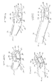
Figures 1 and 2 show front and perspective views, respectively, of an induction system suitable for use in a machine according to one embodiment of the present invention. SpecificallyFigures 1 and 2 show anair intake duct 10 suitable for use in a vehicle internal combustion engine. Theduct 10 comprises afront side 12 and a rear side (not pictured) joined by anupper edge 14 and alower edge 16. Theduct 10 also comprises anend portion 18 and an open-endedportion 20, the open-endedportion 20 leading to an internal combustion engine of a vehicle (not shown). Theedges end portion 18 to the open-ended portion 20) and the transverse direction (i.e. from thefront side 12 to the rear side). The width of thefront side 12 and rear side is greater than the width of theedges front side 12 and rear side are parallel to each other and theedges - The
duct 10 further comprises a generallyrectangular inlet 22 protruding from itsfront side 12 located adjacent theend portion 18. Theinlet 22 comprises anupper portion 24 and alower portion 26 joined by afirst side portion 28 and asecond side portion 30. Theinlet 22 has a generally rectangularopen face 32 at the inlet front. Thefirst side portion 28 of theinlet 22 is joined to thefront side 12 of theduct 10 by a generallycurved surface 34. Thelower portion 26 of theinlet 22 is joined substantially perpendicularly to thefront side 12 of theduct 10. Thesecond side portion 30 of theinlet 22 is joined to theend portion 18 of theduct 10 and theupper portion 24 of theinlet 22 is joined to theupper edge 14 of theduct 10. - The first and
second side portions inlet 22 each comprise acircular opening 36 and 38, respectively, located generally midway between theupper portion 24 andlower portion 26 of theinlet 22, and located generally midway between the front end (i.e. at the end at whichfront face 32 is located) and a rear end (i.e. at the end at which thecurve 34 is located) of theinlet 22. - The
openings 36, 38 are connected by ahollow pipe 40 of circular cross-section and of constant diameter. A typical cross-sectional area of thepipe 40 is approximately 1% of the cross-sectional area of thefront face 32. Thepipe 40 comprises two generallytoroidal sections cylindrical section 46. The firsttoroidal section 42 is joined at its upper end to the outwardly-facing side of opening 36 and is joined at its lower end to a first end of thecylindrical section 46. The secondtoroidal section 44 is joined at its upper end to the outwardly-facing side of opening 38 and is joined at its lower end to a second end of thecylindrical section 46. The joins between the first and secondtoroidal sections pipe 40 and theopenings 36, 38, respectively, are air tight. Thecylindrical section 40 is below, and is generally parallel to, thelower portion 26 of theinlet 22. There is a gap between thelower portion 26 of theinlet 22 and the upper edge of thecylindrical section 46 of thepipe 40. -
Figure 3 shows the location of the engineair intake duct 10 within a vehicle in one embodiment of the invention. In particular,Figure 3 shows a vertical cross section of one side portion of avehicle bonnet 100 having an engineair intake duct 10. Thebonnet 100 provides a closure member for anengine compartment 102 and is formed from an external panel 100A and an internal panel 100B. The external and internal panels 100A, 100B are joined together by welds although other joining technologies are also useful. When joined to the external panel 100A, the internal panel 100B is shaped in such a manner as to define an air conduit at the side of thebonnet 100. This air conduit is arranged to draw ram air from the front of the vehicle (that is, flowing into or out of the page in relation to the cross-section as shown inFigure 3 ) and then in the direction ofarrow 104. Note that a similar arrangement on the other side of the bonnet 100 (not shown) may also be useful. More than two air conduits may also be useful. - In the embodiment shown the
bonnet 100 is of the clamshell type, having a downwardly dependinglip 106 provided around an outer peripheral edge of thebonnet 100. With thebonnet 100 in a closed condition agap 108 is provided between a lower edge of thelip 106 andvehicle body 110. Thevehicle body 110 is typically formed from a plurality of separate body panels, and the area shown inFigure 3 may be formed by the intersection of a bumper fascia panel, a headlamp assembly or light cluster and/or a fender panel, also known as a 'wing panel'. In the present embodiment thegap 108 is around 6mm in width although other arrangements are also useful. It is to be understood that other bonnet types are also useful. - Inboard of the
lip 106 of thebonnet 100, but outboard of theengine compartment 102 is provided aconvergence region 112. Air drawn through the bonnet air conduit is drawn into theconvergence region 112 and subsequently through thefront face 32 of theinlet 22 into theduct 10. - As shown in
Figure 3 air may also be drawn into theconvergence region 112, and thereby into theinlet 22, through thegap 108 between thebonnet 100 and vehicle body 110 (i.e. in the direction of arrow 114). That is, a leak path exists for air into theinlet 22 from around theduct 10 and not just from the bonnet air conduit. Theconvergence region 112 is therefore a region in which an air flow path through the bonnet air conduit converges with an air flow path throughgap 108 betweenbonnet 100 andvehicle body 110. - The
front face 32 of theinlet 22 is shown inFigure 3 facing in a substantially lateral direction relative to a longitudinal axis of the vehicle; however, theduct 10 may be arranged such that thefront face 32 of theinlet 22 faces in a substantially upwards direction relative to a floor of the vehicle. Other directions may also be useful. - To understand the effect on the airflow caused by the inclusion of
pipe 40, consider first theduct 10 shown inFigures 1 and 2 , but in the absence of theopenings 36, 38 and thepipe 40. Air from outside the vehicle is drawn into theinlet 22 via thefront face 32 and directed through theduct 10 towards theopen end 20 and onto the vehicle engine. In the vicinity of the corner defined by thejoin 34, the characteristics of the airflow are altered. In particular, and assuming laminar flow, since pressure increases as the radius of curvature of a streamline increases, then the pressure of the air flowing round the inside of thecorner 34 is lower than the pressure of the air flowing round the outside of thecorner 34. This is depicted schematically inFigure 4 , wherein streamlines 60, 62, 64 show the laminar flow of a fluid (such as air) round a corner, andarrow 66 shows the direction of increasing pressure. The direction of flow along thestreamlines 60, 62, 64 may be in either direction. Since a region of lower pressure leads to a region of higher velocity, the velocity of the air flowing along streamline 60 is greater than the velocity of the air flowing alongstreamline 64. Therefore, the velocity of the air flowing round the inside of thecorner 34 is greater than the velocity of the air flowing round the outside of thecorner 34. - The above-described scenario means that there is a relatively large variation of air velocity across any given cross section of the
inlet 22, with a relatively high air velocity close to the inside of thecorner 34. The velocity of the air at all points within theduct 10 must be below a certain maximum value in order to ensure that particles or debris are not drawn into theduct 10. Therefore, the large variation in velocity across theinlet 22 is undesirable because the amount of air that may be drawn into the vehicle engine via theduct 10 is reduced so as to meet the maximum velocity constraint. - Consider now the
duct 10 with theopenings 36, 38 and thepipe 40 included. The air in the internal region of theduct 10 in the vicinity of opening 36 is in fluid communication with the air in the internal region of theduct 10 in the vicinity of opening 38 (that is, air may flow freely throughpipe 40 from one internal region to the other. Air from outside the vehicle enters theinlet 22 via thefront face 32. The air flowing in the vicinity of opening 36 has a higher velocity than the air flowing in the vicinity of opening 38. In turn, the pressure of the air in the vicinity of opening 36 is lower than the pressure of the air in the vicinity of opening 38. Therefore, there is a pressure difference through thepipe 40. This causes a flow of air through thepipe 40 from opening 36 to opening 38. This reduces the pressure difference between the two ends of thepipe 40 such that the velocity of the air in the vicinity of opening 36 is decreased while the velocity of the air in the vicinity of opening 38 is increased. The variation in velocity across theinlet 22 is therefore smaller when thepipe 40 is included in theduct arrangement 10 compared to a similar duct arrangement in the absence of such an auxiliary pipe. -
Figures 4 and5 show front and perspective views, respectively, of an engine air intake duct 10' according to another embodiment of the present invention. Similarly to the embodiment shown inFigures 1 and 2 , the duct 10' comprises a front side 12', a rear side (not pictured), an upper edge 14', a lower edge 16', an end portion 18' and an open-ended portion 20'. Also similar to the embodiment shown inFigures 1 and 2 , the duct 10' has a generally rectangular inlet 22' protruding from the front side 12' and comprising an upper portion 24', a lower portion 26', a first side portion 28', a second side portion 30', and a front face 32'. - As in the previous embodiment, the first and second side portions 28' and 30' comprise an opening 36' and 38', respectively; however, unlike in the previous embodiment, only the second opening 38' is circular-shaped. The first opening 36' is generally oblong-shaped with its vertical width greater than its transverse width.
- Like in the previous embodiment, the openings 36', 38' are connected by a hollow pipe 40'. The pipe 40' comprises two generally curved sections 42', 44' and a generally uniform section 46'. Unlike in the previous embodiment, the upper edge of the uniform section 46' sits flush to the lower portion 26' of the inlet 22'.
- The
opening 36 in the embodiment shown inFigures 1 and 2 may lead to a relatively local reduction in air velocity in its vicinity. The opening 36' in the embodiment shown inFigures 5 and 6 , however, is designed such that the high-pressure air flowing around the outside of corner 34' that is drawn in the direction of the pressure gradient through pipe 40' is used to provide a more even reduction in the velocity of the air flowing in the vicinity of side portion 28'. - Two possible embodiments of an auxiliary pipe attached to an engine air intake duct are described above; however, it is to be understood that such an auxiliary pipe may be shaped differently to these. It is to be understood also that the openings to which such an auxiliary pipe connects need not be positioned or shaped as shown in the examples above; rather, the auxiliary pipe may run from an opening located at any location of relatively low pressure to an opening located at any location of relatively high pressure (that is, the opening at the ends of the pipe are located such that there is a pressure difference through the pipe). The openings may be located at any location on the engine air intake duct (i.e. not necessarily on the inlet walls).
- In another embodiment (not shown) one end of an auxiliary pipe attached to an engine air intake duct splits into a plurality of sections via a manifold, each section connecting to one of a plurality of duct openings. In a further embodiment, more than one end comprises a manifold. The inclusion of more than one auxiliary pipe may also be advantageous.
- Depending on the location and the orientation of the air intake duct, and the device or machine to which the duct is connected and supplying air, use of a manifold in this way may facilitate tuning for a given volumetric airflow, and/or optimise the acoustic quality and performance in use.
- In one embodiment, the ends of an auxiliary pipe are positioned close to the front face of an inlet rather than deeper into an engine air intake duct in order to reduce the effect of turbulence within the duct. Turbulent flow within the duct is undesirable because it increases the amount of work to be done by the system in order to draw air into the engine.
- In a further embodiment, the ends of an auxiliary pipe are positioned close to a corner region of the engine air intake duct (that is, the openings in the duct to which the ends of the pipe are positioned are in the vicinity of internal regions of the duct where the airflow is changing direction).
- Note that a simple opening in an area of low pressure (i.e. high velocity) within an engine air intake duct (i.e. in the absence of an auxiliary pipe) would not be suitable because of increased noise and vibration, and because the region surrounding the duct may be wet and so would draw water into the duct.
- The embodiments of the air intake duct as described above may be configured to supply air to any suitable device or machine, and are not limited to the application of induction systems for engines. It is envisaged that, for example, the air intake duct according to an embodiment as described above, may be readily employed as part of an air supply to a compressor or other air handling device. Such a compressor, fitted with an air duct as described above, may also benefit from the aforementioned advantages provided by the reduction in pressure differences across an air intake duct as has been described above, along with the attendant reduction in ingestion of particulate matter, such as dust and sand, which may be otherwise entrained in the surrounding air.
- Further aspects of the present invention are set out in the following numbered Clauses:
- Clause 1: An air intake apparatus suitable for use in an induction system of a machine, the apparatus comprising: an air intake duct comprising an inlet, through which air may be drawn into the machine; and a device configured to communicate at least one internal region of the duct at a first pressure with at least one internal region of the duct at a second pressure, so as to reduce the difference between the first pressure and the second pressure.
- Clause 2: The apparatus according to Clause 1, wherein the device configured to communicate is external to the duct.
- Clause 3: The apparatus according to Clause 1, wherein the machine is a vehicle internal combustion engine.
- Clause 4: The apparatus according to
Clause 2, wherein the device external to the duct comprises at least one auxiliary pipe, each auxiliary pipe comprising at least two ends, each end comprising at least one opening, at least one of the openings being located to open into the internal region of the air intake duct at the first pressure, and at least one of the openings being located to open into the internal region of the air intake duct at the second pressure. - Clause 5: The apparatus according to Clause 4, wherein at least one opening is located adjacent a front face of the inlet.
- Clause 6: The apparatus according to Clause 4, wherein at least one opening is located close to a corner region of the air intake duct.
- Clause 7: The apparatus according to Clause 4, wherein at least one opening is located along the length of the air intake duct.
- Clause 8: The apparatus according to Clause 4, wherein at least one opening is generally circular-shaped.
- Clause 9: The apparatus according to Clause 4, wherein at least one opening is generally oblong-shaped.
- Clause 10: The apparatus according to Clause 4, wherein the at least one auxiliary pipe is of generally circular cross-section.
- Clause 11: The apparatus according to Clause 4, wherein the at least one auxiliary pipe comprises at least one manifold leading to a plurality of openings at at least one end of the pipe.
- Clause 12: The apparatus according to Clause 4, wherein the at least one auxiliary pipe sits flush to the air intake duct.
- Clause 13: The apparatus according to Clause 4, wherein the cross-sectional area of the at least one auxiliary pipe is substantially 1% of the cross-sectional area of the inlet.
- Clause 14: A vehicle comprising at least one air intake apparatus according to
Clause 3. - Clause 15: A vehicle according to
Clause 14, further comprising: a vehicle body; an engine compartment housing an engine; and a bonnet movably coupled to the body and arranged to provide a closure member for the engine compartment, the bonnet being movable between open and closed conditions to allow access to the engine compartment, wherein the air intake apparatus is located below the bonnet within the vehicle body, adjacent the engine compartment. - Clause 16: A vehicle according to
Clause 14, wherein the vehicle is provided with first and second air flow paths whereby air may be supplied to the air intake duct, the first flow path comprising a bonnet conduit for providing ram air to the inlet, and the second flow path being provided by a gap between a side edge of the bonnet and the body of the vehicle, whereby ambient air may be drawn through the gap to the inlet. - Clause 17: A vehicle according to
Clause 14, wherein the inlet of the air intake duct is arranged to face substantially laterally relative to a longitudinal vehicle axis. - Clause 18: A vehicle according to
Clause 14, wherein the inlet of the air intake duct is arranged to face in a substantially upwards direction relative to a vehicle floor.
Claims (15)
- An air intake apparatus suitable for use in an induction system of a machine, the apparatus comprising:an air intake duct comprising an inlet, through which air may be drawn into the machine; andmeans configured to communicate at least one internal region of the duct at a first pressure with at least one internal region of the duct at a second pressure, so as to reduce the difference between the first pressure and the second pressure.
- The apparatus according to claim 1, wherein the means configured to communicate is external to the duct.
- The apparatus according to claim 1 or claim 2, wherein the machine is a vehicle internal combustion engine.
- The apparatus according to claim 2 or claim 3, wherein the means external to the duct comprises at least one auxiliary pipe, each auxiliary pipe comprising at least two ends, each end comprising at least one opening, at least one of the openings being located to open into the internal region of the air intake duct at the first pressure, and at least one of the openings being located to open into the internal region of the air intake duct at the second pressure.
- The apparatus according to claim 4, wherein at least one opening is located adjacent a front face of the inlet.
- The apparatus according to claim 4 or claim 5, wherein at least one opening is located close to a corner region of the air intake duct.
- The apparatus according to any of claims 4 to 6, wherein at least one opening is located along the length of the air intake duct.
- The apparatus according to any of claims 4 to 7, wherein at least one opening is generally circular-shaped or oblong-shaped.
- The apparatus according to any of claims 4 to 8, wherein the at least one auxiliary pipe is of generally circular cross-section and/or comprises at least one manifold leading to a plurality of openings at at least one end of the pipe.
- The apparatus according to any of claims 4 to 9, wherein the at least one auxiliary pipe sits flush to the air intake duct.
- The apparatus according to any of claims 4 to 10, wherein the cross-sectional area of the at least one auxiliary pipe is substantially 1% of the cross-sectional area of the inlet.
- A vehicle comprising at least one air intake apparatus according to any of claims 3 to 11.
- A vehicle according to claim 12, further comprising:a vehicle body;an engine compartment housing an engine; anda bonnet movably coupled to the body and arranged to provide a closure member for the engine compartment, the bonnet being movable between open and closed conditions to allow access to the engine compartment,wherein the air intake apparatus is located below the bonnet within the vehicle body, adjacent the engine compartment.
- A vehicle according to claim 12 or claim 13, wherein the vehicle is provided with first and second air flow paths whereby air may be supplied to the air intake duct, the first flow path comprising a bonnet conduit for providing ram air to the inlet, and the second flow path being provided by a gap between a side edge of the bonnet and the body of the vehicle, whereby ambient air may be drawn through the gap to the inlet.
- A vehicle according to any of claims 12 to 14, wherein the inlet of the air intake duct is arranged to face substantially laterally relative to a longitudinal vehicle axis or in a substantially upwards direction relative to a vehicle floor.
Applications Claiming Priority (1)
| Application Number | Priority Date | Filing Date | Title |
|---|---|---|---|
| GB1414486.9A GB2529241A (en) | 2014-08-15 | 2014-08-15 | Air intake apparatus |
Publications (2)
| Publication Number | Publication Date |
|---|---|
| EP2985444A1 true EP2985444A1 (en) | 2016-02-17 |
| EP2985444B1 EP2985444B1 (en) | 2018-10-10 |
Family
ID=51662469
Family Applications (1)
| Application Number | Title | Priority Date | Filing Date |
|---|---|---|---|
| EP15180904.3A Active EP2985444B1 (en) | 2014-08-15 | 2015-08-13 | Air intake apparatus |
Country Status (2)
| Country | Link |
|---|---|
| EP (1) | EP2985444B1 (en) |
| GB (1) | GB2529241A (en) |
Citations (4)
| Publication number | Priority date | Publication date | Assignee | Title |
|---|---|---|---|---|
| US2037940A (en) * | 1932-09-10 | 1936-04-21 | Edward A Stalker | Means for preventing the separation of the flow from curved surfaces |
| US3353562A (en) * | 1965-04-01 | 1967-11-21 | American Standard Inc | Guiding fluid around a bend |
| US20030131897A1 (en) * | 2002-01-14 | 2003-07-17 | Siemens Vdo Automotive, Inc. | Bifurcated duct for a vehicle induction system |
| WO2013107903A1 (en) * | 2012-01-20 | 2013-07-25 | Jaguar Land Rover Limited | Motor vehicle with improved air intake apparatus |
Family Cites Families (7)
| Publication number | Priority date | Publication date | Assignee | Title |
|---|---|---|---|---|
| US2745394A (en) * | 1954-06-28 | 1956-05-15 | Holley Carburetor Co | Manifold assembly for internal combustion engines |
| JPS54118915A (en) * | 1978-03-07 | 1979-09-14 | Toyota Motor Corp | Suction controller for internal combustion engine |
| JPS5862352A (en) * | 1981-10-07 | 1983-04-13 | Aichi Mach Ind Co Ltd | Fuel spray promoter for internal-combustion engine |
| JPS5862315A (en) * | 1981-10-07 | 1983-04-13 | Mazda Motor Corp | Suction device of engine |
| DE10038011A1 (en) * | 2000-08-04 | 2002-02-14 | Porsche Ag | suction |
| US20050172924A1 (en) * | 2004-02-09 | 2005-08-11 | Simon David N. | Air management systems |
| US7556009B2 (en) * | 2007-09-07 | 2009-07-07 | Advanced Flow Engineering, Inc. | Air intake manifold for coupling the output of a compressor to the air intake of an internal combustion engine |
-
2014
- 2014-08-15 GB GB1414486.9A patent/GB2529241A/en not_active Withdrawn
-
2015
- 2015-08-13 EP EP15180904.3A patent/EP2985444B1/en active Active
Patent Citations (4)
| Publication number | Priority date | Publication date | Assignee | Title |
|---|---|---|---|---|
| US2037940A (en) * | 1932-09-10 | 1936-04-21 | Edward A Stalker | Means for preventing the separation of the flow from curved surfaces |
| US3353562A (en) * | 1965-04-01 | 1967-11-21 | American Standard Inc | Guiding fluid around a bend |
| US20030131897A1 (en) * | 2002-01-14 | 2003-07-17 | Siemens Vdo Automotive, Inc. | Bifurcated duct for a vehicle induction system |
| WO2013107903A1 (en) * | 2012-01-20 | 2013-07-25 | Jaguar Land Rover Limited | Motor vehicle with improved air intake apparatus |
Also Published As
| Publication number | Publication date |
|---|---|
| GB2529241A (en) | 2016-02-17 |
| GB201414486D0 (en) | 2014-10-01 |
| EP2985444B1 (en) | 2018-10-10 |
Similar Documents
| Publication | Publication Date | Title |
|---|---|---|
| US20100300066A1 (en) | Turbojet engine for aircraft | |
| CN202991290U (en) | intake manifold | |
| JP6040128B2 (en) | EGR device | |
| CN108569133A (en) | The pipeline of vehicle constructs | |
| JP2015505521A (en) | Vehicle with improved intake system | |
| US11724589B2 (en) | Motor vehicle bonnet seal arrangement | |
| CA2934543C (en) | Cooling device and construction machine | |
| CN100475590C (en) | Intermediate cooler setting structure with supercharge equipment engine | |
| JP2010254023A (en) | Vehicle air resistance reduction structure | |
| JP6580155B2 (en) | Piping connection structure | |
| JP6350256B2 (en) | Engine intake system | |
| EP2985444B1 (en) | Air intake apparatus | |
| JP2015120451A (en) | Vehicle lower part structure | |
| JP6089790B2 (en) | Intake device for vehicle engine | |
| KR20120056667A (en) | Submerged inlet, forming method for the same and aircraft having the same | |
| CN106133301A (en) | The subsidiary engine assembling structure of internal combustion engine for vehicle | |
| JP5180760B2 (en) | Intake manifold for internal combustion engine | |
| JP5252306B2 (en) | Engine intake system | |
| KR102370863B1 (en) | Bypass valve in vacuum generator | |
| JP5855495B2 (en) | Intake manifold | |
| JP2007092696A (en) | Air intake intake structure for vehicle air intake duct | |
| JP6355159B2 (en) | Vehicle front structure | |
| JP6252145B2 (en) | Vehicle structure | |
| KR101294083B1 (en) | Device for reducing air current noise of turbo-charger engine | |
| US10704460B2 (en) | Recirculation valve for turbo charger engine |
Legal Events
| Date | Code | Title | Description |
|---|---|---|---|
| PUAI | Public reference made under article 153(3) epc to a published international application that has entered the european phase |
Free format text: ORIGINAL CODE: 0009012 |
|
| AK | Designated contracting states |
Kind code of ref document: A1 Designated state(s): AL AT BE BG CH CY CZ DE DK EE ES FI FR GB GR HR HU IE IS IT LI LT LU LV MC MK MT NL NO PL PT RO RS SE SI SK SM TR |
|
| AX | Request for extension of the european patent |
Extension state: BA ME |
|
| 17P | Request for examination filed |
Effective date: 20160817 |
|
| RBV | Designated contracting states (corrected) |
Designated state(s): AL AT BE BG CH CY CZ DE DK EE ES FI FR GB GR HR HU IE IS IT LI LT LU LV MC MK MT NL NO PL PT RO RS SE SI SK SM TR |
|
| GRAP | Despatch of communication of intention to grant a patent |
Free format text: ORIGINAL CODE: EPIDOSNIGR1 |
|
| STAA | Information on the status of an ep patent application or granted ep patent |
Free format text: STATUS: GRANT OF PATENT IS INTENDED |
|
| RIC1 | Information provided on ipc code assigned before grant |
Ipc: F15D 1/04 20060101ALI20180426BHEP Ipc: F02M 35/10 20060101AFI20180426BHEP |
|
| INTG | Intention to grant announced |
Effective date: 20180517 |
|
| GRAS | Grant fee paid |
Free format text: ORIGINAL CODE: EPIDOSNIGR3 |
|
| GRAA | (expected) grant |
Free format text: ORIGINAL CODE: 0009210 |
|
| STAA | Information on the status of an ep patent application or granted ep patent |
Free format text: STATUS: THE PATENT HAS BEEN GRANTED |
|
| AK | Designated contracting states |
Kind code of ref document: B1 Designated state(s): AL AT BE BG CH CY CZ DE DK EE ES FI FR GB GR HR HU IE IS IT LI LT LU LV MC MK MT NL NO PL PT RO RS SE SI SK SM TR |
|
| REG | Reference to a national code |
Ref country code: GB Ref legal event code: FG4D |
|
| REG | Reference to a national code |
Ref country code: CH Ref legal event code: EP Ref country code: AT Ref legal event code: REF Ref document number: 1051530 Country of ref document: AT Kind code of ref document: T Effective date: 20181015 |
|
| REG | Reference to a national code |
Ref country code: IE Ref legal event code: FG4D |
|
| REG | Reference to a national code |
Ref country code: DE Ref legal event code: R096 Ref document number: 602015017751 Country of ref document: DE |
|
| REG | Reference to a national code |
Ref country code: NL Ref legal event code: MP Effective date: 20181010 |
|
| REG | Reference to a national code |
Ref country code: LT Ref legal event code: MG4D |
|
| REG | Reference to a national code |
Ref country code: AT Ref legal event code: MK05 Ref document number: 1051530 Country of ref document: AT Kind code of ref document: T Effective date: 20181010 |
|
| PG25 | Lapsed in a contracting state [announced via postgrant information from national office to epo] |
Ref country code: NL Free format text: LAPSE BECAUSE OF FAILURE TO SUBMIT A TRANSLATION OF THE DESCRIPTION OR TO PAY THE FEE WITHIN THE PRESCRIBED TIME-LIMIT Effective date: 20181010 |
|
| PG25 | Lapsed in a contracting state [announced via postgrant information from national office to epo] |
Ref country code: ES Free format text: LAPSE BECAUSE OF FAILURE TO SUBMIT A TRANSLATION OF THE DESCRIPTION OR TO PAY THE FEE WITHIN THE PRESCRIBED TIME-LIMIT Effective date: 20181010 Ref country code: AT Free format text: LAPSE BECAUSE OF FAILURE TO SUBMIT A TRANSLATION OF THE DESCRIPTION OR TO PAY THE FEE WITHIN THE PRESCRIBED TIME-LIMIT Effective date: 20181010 Ref country code: IS Free format text: LAPSE BECAUSE OF FAILURE TO SUBMIT A TRANSLATION OF THE DESCRIPTION OR TO PAY THE FEE WITHIN THE PRESCRIBED TIME-LIMIT Effective date: 20190210 Ref country code: NO Free format text: LAPSE BECAUSE OF FAILURE TO SUBMIT A TRANSLATION OF THE DESCRIPTION OR TO PAY THE FEE WITHIN THE PRESCRIBED TIME-LIMIT Effective date: 20190110 Ref country code: LT Free format text: LAPSE BECAUSE OF FAILURE TO SUBMIT A TRANSLATION OF THE DESCRIPTION OR TO PAY THE FEE WITHIN THE PRESCRIBED TIME-LIMIT Effective date: 20181010 Ref country code: PL Free format text: LAPSE BECAUSE OF FAILURE TO SUBMIT A TRANSLATION OF THE DESCRIPTION OR TO PAY THE FEE WITHIN THE PRESCRIBED TIME-LIMIT Effective date: 20181010 Ref country code: HR Free format text: LAPSE BECAUSE OF FAILURE TO SUBMIT A TRANSLATION OF THE DESCRIPTION OR TO PAY THE FEE WITHIN THE PRESCRIBED TIME-LIMIT Effective date: 20181010 Ref country code: BG Free format text: LAPSE BECAUSE OF FAILURE TO SUBMIT A TRANSLATION OF THE DESCRIPTION OR TO PAY THE FEE WITHIN THE PRESCRIBED TIME-LIMIT Effective date: 20190110 Ref country code: FI Free format text: LAPSE BECAUSE OF FAILURE TO SUBMIT A TRANSLATION OF THE DESCRIPTION OR TO PAY THE FEE WITHIN THE PRESCRIBED TIME-LIMIT Effective date: 20181010 Ref country code: LV Free format text: LAPSE BECAUSE OF FAILURE TO SUBMIT A TRANSLATION OF THE DESCRIPTION OR TO PAY THE FEE WITHIN THE PRESCRIBED TIME-LIMIT Effective date: 20181010 |
|
| PG25 | Lapsed in a contracting state [announced via postgrant information from national office to epo] |
Ref country code: RS Free format text: LAPSE BECAUSE OF FAILURE TO SUBMIT A TRANSLATION OF THE DESCRIPTION OR TO PAY THE FEE WITHIN THE PRESCRIBED TIME-LIMIT Effective date: 20181010 Ref country code: AL Free format text: LAPSE BECAUSE OF FAILURE TO SUBMIT A TRANSLATION OF THE DESCRIPTION OR TO PAY THE FEE WITHIN THE PRESCRIBED TIME-LIMIT Effective date: 20181010 Ref country code: SE Free format text: LAPSE BECAUSE OF FAILURE TO SUBMIT A TRANSLATION OF THE DESCRIPTION OR TO PAY THE FEE WITHIN THE PRESCRIBED TIME-LIMIT Effective date: 20181010 Ref country code: GR Free format text: LAPSE BECAUSE OF FAILURE TO SUBMIT A TRANSLATION OF THE DESCRIPTION OR TO PAY THE FEE WITHIN THE PRESCRIBED TIME-LIMIT Effective date: 20190111 Ref country code: PT Free format text: LAPSE BECAUSE OF FAILURE TO SUBMIT A TRANSLATION OF THE DESCRIPTION OR TO PAY THE FEE WITHIN THE PRESCRIBED TIME-LIMIT Effective date: 20190210 |
|
| REG | Reference to a national code |
Ref country code: DE Ref legal event code: R097 Ref document number: 602015017751 Country of ref document: DE |
|
| PG25 | Lapsed in a contracting state [announced via postgrant information from national office to epo] |
Ref country code: DK Free format text: LAPSE BECAUSE OF FAILURE TO SUBMIT A TRANSLATION OF THE DESCRIPTION OR TO PAY THE FEE WITHIN THE PRESCRIBED TIME-LIMIT Effective date: 20181010 Ref country code: IT Free format text: LAPSE BECAUSE OF FAILURE TO SUBMIT A TRANSLATION OF THE DESCRIPTION OR TO PAY THE FEE WITHIN THE PRESCRIBED TIME-LIMIT Effective date: 20181010 Ref country code: CZ Free format text: LAPSE BECAUSE OF FAILURE TO SUBMIT A TRANSLATION OF THE DESCRIPTION OR TO PAY THE FEE WITHIN THE PRESCRIBED TIME-LIMIT Effective date: 20181010 |
|
| PLBE | No opposition filed within time limit |
Free format text: ORIGINAL CODE: 0009261 |
|
| STAA | Information on the status of an ep patent application or granted ep patent |
Free format text: STATUS: NO OPPOSITION FILED WITHIN TIME LIMIT |
|
| PG25 | Lapsed in a contracting state [announced via postgrant information from national office to epo] |
Ref country code: EE Free format text: LAPSE BECAUSE OF FAILURE TO SUBMIT A TRANSLATION OF THE DESCRIPTION OR TO PAY THE FEE WITHIN THE PRESCRIBED TIME-LIMIT Effective date: 20181010 Ref country code: SM Free format text: LAPSE BECAUSE OF FAILURE TO SUBMIT A TRANSLATION OF THE DESCRIPTION OR TO PAY THE FEE WITHIN THE PRESCRIBED TIME-LIMIT Effective date: 20181010 Ref country code: RO Free format text: LAPSE BECAUSE OF FAILURE TO SUBMIT A TRANSLATION OF THE DESCRIPTION OR TO PAY THE FEE WITHIN THE PRESCRIBED TIME-LIMIT Effective date: 20181010 Ref country code: SK Free format text: LAPSE BECAUSE OF FAILURE TO SUBMIT A TRANSLATION OF THE DESCRIPTION OR TO PAY THE FEE WITHIN THE PRESCRIBED TIME-LIMIT Effective date: 20181010 |
|
| REG | Reference to a national code |
Ref country code: GB Ref legal event code: 746 Effective date: 20190814 |
|
| 26N | No opposition filed |
Effective date: 20190711 |
|
| REG | Reference to a national code |
Ref country code: DE Ref legal event code: R084 Ref document number: 602015017751 Country of ref document: DE |
|
| PG25 | Lapsed in a contracting state [announced via postgrant information from national office to epo] |
Ref country code: SI Free format text: LAPSE BECAUSE OF FAILURE TO SUBMIT A TRANSLATION OF THE DESCRIPTION OR TO PAY THE FEE WITHIN THE PRESCRIBED TIME-LIMIT Effective date: 20181010 |
|
| PG25 | Lapsed in a contracting state [announced via postgrant information from national office to epo] |
Ref country code: TR Free format text: LAPSE BECAUSE OF FAILURE TO SUBMIT A TRANSLATION OF THE DESCRIPTION OR TO PAY THE FEE WITHIN THE PRESCRIBED TIME-LIMIT Effective date: 20181010 |
|
| PG25 | Lapsed in a contracting state [announced via postgrant information from national office to epo] |
Ref country code: CH Free format text: LAPSE BECAUSE OF NON-PAYMENT OF DUE FEES Effective date: 20190831 Ref country code: LI Free format text: LAPSE BECAUSE OF NON-PAYMENT OF DUE FEES Effective date: 20190831 Ref country code: LU Free format text: LAPSE BECAUSE OF NON-PAYMENT OF DUE FEES Effective date: 20190813 Ref country code: MC Free format text: LAPSE BECAUSE OF FAILURE TO SUBMIT A TRANSLATION OF THE DESCRIPTION OR TO PAY THE FEE WITHIN THE PRESCRIBED TIME-LIMIT Effective date: 20181010 |
|
| REG | Reference to a national code |
Ref country code: BE Ref legal event code: MM Effective date: 20190831 |
|
| PG25 | Lapsed in a contracting state [announced via postgrant information from national office to epo] |
Ref country code: IE Free format text: LAPSE BECAUSE OF NON-PAYMENT OF DUE FEES Effective date: 20190813 |
|
| PG25 | Lapsed in a contracting state [announced via postgrant information from national office to epo] |
Ref country code: BE Free format text: LAPSE BECAUSE OF NON-PAYMENT OF DUE FEES Effective date: 20190831 |
|
| PG25 | Lapsed in a contracting state [announced via postgrant information from national office to epo] |
Ref country code: CY Free format text: LAPSE BECAUSE OF FAILURE TO SUBMIT A TRANSLATION OF THE DESCRIPTION OR TO PAY THE FEE WITHIN THE PRESCRIBED TIME-LIMIT Effective date: 20181010 |
|
| PG25 | Lapsed in a contracting state [announced via postgrant information from national office to epo] |
Ref country code: MT Free format text: LAPSE BECAUSE OF FAILURE TO SUBMIT A TRANSLATION OF THE DESCRIPTION OR TO PAY THE FEE WITHIN THE PRESCRIBED TIME-LIMIT Effective date: 20181010 Ref country code: HU Free format text: LAPSE BECAUSE OF FAILURE TO SUBMIT A TRANSLATION OF THE DESCRIPTION OR TO PAY THE FEE WITHIN THE PRESCRIBED TIME-LIMIT; INVALID AB INITIO Effective date: 20150813 |
|
| PG25 | Lapsed in a contracting state [announced via postgrant information from national office to epo] |
Ref country code: MK Free format text: LAPSE BECAUSE OF FAILURE TO SUBMIT A TRANSLATION OF THE DESCRIPTION OR TO PAY THE FEE WITHIN THE PRESCRIBED TIME-LIMIT Effective date: 20181010 |
|
| P01 | Opt-out of the competence of the unified patent court (upc) registered |
Effective date: 20230528 |
|
| PGFP | Annual fee paid to national office [announced via postgrant information from national office to epo] |
Ref country code: DE Payment date: 20250820 Year of fee payment: 11 |
|
| PGFP | Annual fee paid to national office [announced via postgrant information from national office to epo] |
Ref country code: GB Payment date: 20250821 Year of fee payment: 11 |
|
| PGFP | Annual fee paid to national office [announced via postgrant information from national office to epo] |
Ref country code: FR Payment date: 20250829 Year of fee payment: 11 |