EP2985400A1 - Linking structure having metal pin interposed between metal link and metal lever - Google Patents
Linking structure having metal pin interposed between metal link and metal lever Download PDFInfo
- Publication number
- EP2985400A1 EP2985400A1 EP14783385.9A EP14783385A EP2985400A1 EP 2985400 A1 EP2985400 A1 EP 2985400A1 EP 14783385 A EP14783385 A EP 14783385A EP 2985400 A1 EP2985400 A1 EP 2985400A1
- Authority
- EP
- European Patent Office
- Prior art keywords
- metal
- lever
- shaft portion
- support shaft
- pin
- Prior art date
- Legal status (The legal status is an assumption and is not a legal conclusion. Google has not performed a legal analysis and makes no representation as to the accuracy of the status listed.)
- Granted
Links
Images



Classifications
-
- E—FIXED CONSTRUCTIONS
- E05—LOCKS; KEYS; WINDOW OR DOOR FITTINGS; SAFES
- E05B—LOCKS; ACCESSORIES THEREFOR; HANDCUFFS
- E05B79/00—Mounting or connecting vehicle locks or parts thereof
- E05B79/02—Mounting of vehicle locks or parts thereof
- E05B79/08—Mounting of individual lock elements in the lock, e.g. levers
-
- E—FIXED CONSTRUCTIONS
- E05—LOCKS; KEYS; WINDOW OR DOOR FITTINGS; SAFES
- E05B—LOCKS; ACCESSORIES THEREFOR; HANDCUFFS
- E05B77/00—Vehicle locks characterised by special functions or purposes
- E05B77/02—Vehicle locks characterised by special functions or purposes for accident situations
- E05B77/10—Allowing opening in case of deformed bodywork, e.g. by preventing deformation of lock parts
-
- F—MECHANICAL ENGINEERING; LIGHTING; HEATING; WEAPONS; BLASTING
- F16—ENGINEERING ELEMENTS AND UNITS; GENERAL MEASURES FOR PRODUCING AND MAINTAINING EFFECTIVE FUNCTIONING OF MACHINES OR INSTALLATIONS; THERMAL INSULATION IN GENERAL
- F16C—SHAFTS; FLEXIBLE SHAFTS; ELEMENTS OR CRANKSHAFT MECHANISMS; ROTARY BODIES OTHER THAN GEARING ELEMENTS; BEARINGS
- F16C11/00—Pivots; Pivotal connections
- F16C11/04—Pivotal connections
- F16C11/06—Ball-joints; Other joints having more than one degree of angular freedom, i.e. universal joints
Definitions
- the present invention relates to a structure for connecting a metal lever and a metal link via a metal pin, and can be used, for example, as a component of a vehicle door locking device (such as a vehicle door lock device, a vehicle closer device, a vehicle remote control device, or a vehicle door handle device).
- a vehicle door locking device such as a vehicle door lock device, a vehicle closer device, a vehicle remote control device, or a vehicle door handle device.
- a structure for connecting a metal lever and a metal link to each other is used in, for example, a connecting region between an outside open lever (metal plate lever) and an open link (metal plate link) disclosed in WO 2011/118356 A1 .
- a connecting leg portion (hook) 12a formed on an open link 12 is inserted and engaged into a noncircular connecting hole portion 11 a formed in an outside open lever 11, thereby connecting the outside open lever 11 and the open link 12 to each other.
- the open link 12 is connected to the outside open lever 11 so as to be rotatable by a necessary amount along a plate surface of the outside open lever 11 (along a surface of the drawing sheet of FIG.
- the outside open lever 11 is pivotably mounted, at a circular support hole 11 b formed in an intermediate portion thereof, to a support shaft 91a formed on a housing body 91.
- a right end portion 11c illustrated in FIG. 2 serves as an input portion
- the above-mentioned noncircular connecting hole portion 11a serves as an output portion.
- the noncircular connecting hole portion 11a is formed by punching using a press.
- the above-mentioned connecting leg portion 12a serves as an input portion
- an upper end portion 12b illustrated in FIG. 2 serves as an output portion.
- the connecting leg portion 12a is formed by a bending process after using a press.
- the connecting leg portion (hook) 12a formed on the metal link (12) is inserted and engaged into the noncircular connecting hole portion 11 a formed in the metal lever (11), thereby mounting the metal link to the metal lever. Accordingly, this structure is advantageous in that the structure is simple and can be manufactured at low cost. However, the connecting leg portion (hook) 12a comes off the noncircular connecting hole portion 11 a easily at the time of assembly, and hence improvement in mountability is desired.
- a structure for connecting a metal lever and a metal link via a metal pin including:
- the support shaft portion is insertable through the connecting hole, and is pivotable and movable in an axial direction of the metal pin by a preset amount with respect to the connecting hole, the head portion is formed at one end portion of the support shaft portion and has a diameter larger than a diameter of the support shaft portion, the connecting shaft portion is formed at the other end portion of the support shaft portion and has a diameter smaller than the diameter of the support shaft portion, and the metal pin comprises an allowable portion formed on at least one axial end portion of the support shaft portion of the metal pin, and the allowable portion is configured to increase an amount of swing of the metal lever on the metal pin in the axial direction of the metal pin.
- the above-mentioned amount of swing of the metal lever on the metal pin in the axial direction of the metal pin is a relative amount of swing.
- the allowable portion is formed on the at least one axial end portion of the support shaft portion of the metal pin, and is configured to increase the amount of swing of the metal lever on the metal pin in the axial direction of the metal pin. Accordingly, the amount of swing of the metal lever on the metal pin in the axial direction of the metal pin can be ensured in a necessary and sufficient manner while minimizing a radial gap between the support shaft portion of the metal pin and the connecting hole of the metal lever at an axial intermediate portion of the support shaft portion of the metal pin.
- the metal lever and the metal link are connected to each other via the metal pin
- the metal pin includes the support shaft portion pivotable and movable in the axial direction of the metal pin by the preset amount with respect to the connecting hole of the metal lever, the head portion (portion capable of preventing the metal lever from coming off the support shaft portion) being formed at one end portion of the support shaft portion and having the diameter larger than the diameter of the support shaft portion, and the connecting shaft portion (to which the metal link is integrally connected at the coupling hole after the metal lever is mounted onto the support shaft portion) being formed at the other end portion of the support shaft portion and having the diameter smaller than the diameter of the support shaft portion.
- the metal lever and the metal link are connected to each other via the metal pin, the metal lever is sandwiched and retained between the metal link (connected to the connecting shaft portion of the metal pin) and the head portion of the metal pin. Therefore, under a state in which the metal lever and the metal link are connected to each other via the metal pin, the metal lever and the metal link do not easily come off the metal pin, and mountability at the time of assembly can be improved.
- a second allowable portion for increasing the amount of swing of the metal lever on the metal pin in the axial direction of the metal pin
- chamfered portion such as a C beveled portion or a R beveled portion (a rounded portion)
- the above-mentioned second allowable portion can also increase the amount of swing of the metal lever on the metal pin in the axial direction of the metal pin.
- the allowable portion can be formed so that only the one axial end portion of the support shaft portion of the metal pin has a diameter smaller than that of a center portion of the support shaft portion and only the one axial end portion has a curved surface shape in radial cross-section.
- the amount of swing of the metal lever to the one axial end portion side can be larger than the amount of swing to the other axial end portion side. Accordingly, a large amount of swing can be set only for a direction requiring swing.
- the allowable portion can be formed so that the entire support shaft portion has a curved surface shape and a center portion of the support shaft portion of the metal pin has a maximum diameter in the support shaft portion.
- the amount of swing of the metal lever can be further larger than the above-mentioned case.
- the amount of swing to the one axial end portion side and the amount of swing to the other axial end portion side can be increased equally.
- the allowable portion can be formed so that the support shaft portion of the metal pin has an arc shape in radial cross-section. In this case, the above-mentioned arc shape (spherical outer shape) enables the metal lever to swing more smoothly.
- the metal link or the metal lever can include a protrusion regulating a swinging direction of the metal lever to a specific direction when the metal lever swings on the metal pin in the axial direction of the metal pin.
- an abutment portion between the metal lever and the protrusion formed on the metal link, or an abutment portion between the metal link and the protrusion formed on the metal lever can serve as a swinging fulcrum. Accordingly, the swinging direction of the metal lever on the metal pin can be stabilized.
- the above-mentioned protrusion be formed as a straight protrusion extending in a radial direction of the metal pin, and the present invention can be embodied even when the above-mentioned protrusion is formed of a point-like protrusion.
- a second allowable portion for increasing the amount of swing of the metal lever on the metal pin in the axial direction of the metal pin can be formed on the other axial end portion of the connecting hole of the metal lever.
- the amount of swing of the metal lever to the one axial end portion side (amount of swing in a case illustrated in FIG. 12 described later) can be larger than the amount of swing to the other axial end portion side. Accordingly, a large amount of swing can be set only for a direction requiring swing of the metal lever.
- FIG. 3 to FIG. 8 are illustrations of a connecting structure according to an embodiment of the present invention, which is used as a component of a vehicle door lock device.
- a connecting structure 20 according to this embodiment, an outside open lever (metal plate lever) 21 and an open link (metal plate link) 22 are connected to each other via (by) a metal connecting pin 23.
- a torsion spring 24 is interposed between the outside open lever 21 and the open link 22, and the open link 22 is biased so that the open link 22 rotates clockwise in FIG. 3 and swings clockwise in FIG. 4 with respect to the outside open lever 21.
- the outside open lever 21 has a circular connecting hole 21 a (see FIG. 4 ) formed in a distal end portion thereof, and has a circular support hole 21b (see FIG. 3 ) formed in an intermediate portion thereof.
- the outside open lever 21 is configured so as to be pivotably mounted at the circular support hole 21 b to a support shaft (not shown) of a housing body (not shown).
- a left end portion 21 c of the outside open lever 21 illustrated in FIG. 3 serves as an input portion, whereas a region of the outside open lever 21, in which the above-mentioned circular connecting hole 21 a is formed, serves as an output portion.
- an operation force of an outside handle which is arranged on an outer side of a door of a vehicle, is input to the left end portion 21 c.
- an operation force of an inside handle which is arranged on an inner side of the door of the vehicle, can be input to the left end portion 21 c.
- the open link 22 includes a region, which has a circular coupling hole 22a formed in a lower end portion thereof illustrated in FIG. 3 , serves as an input portion, whereas an upper end portion 22b of the open link 22 illustrated in FIG. 3 serves as an output portion.
- the coupling hole 22a of the open link 22 is fitted into the connecting pin 23, and is integrally connected to the connecting pin 23.
- the open link 22 includes a pair of straight protrusions 22c extending in a radial direction (horizontal direction in FIG. 3 ) of the connecting pin 23.
- Each of the straight protrusions 22c is configured to regulate a swinging direction of the outside open lever 21 to a specific direction (lateral direction in illustrations of FIG. 7 and FIG.
- a support shaft portion 23a is formed in an axial intermediate region of the connecting pin 23.
- a head portion 23b is formed at one end portion (left end portion illustrated in FIG. 4 ) of the support shaft portion 23a, whereas a connecting shaft portion 23c and a swaging fixing portion 23d are formed at the other end portion (right end portion illustrated in FIG. 4 ) of the support shaft portion 23a.
- the support shaft portion 23a can be inserted through the connecting hole 21 a of the outside open lever 21 (the support shaft portion 23a has an outer diameter smaller than an inner diameter of the connecting hole 21 a).
- the support shaft portion 23a is pivotable and movable in the axial direction by a preset amount with respect to the connecting hole 21 a.
- a spherical curved surface 23a1 (a curvature of the spherical curved surface 23a1 can be set as appropriate) is formed on each axial end portion (each lateral end portion illustrated in FIG. 4 ) of the support shaft portion 23a.
- the spherical curved surface 23a1 serves as an allowable portion for increasing an amount of swing of the outside open lever 21 on the connecting pin 23 in the axial direction.
- the head portion 23b has a diameter larger than that of the support shaft portion 23a, and larger than the inner diameter of the connecting hole 21 a of the outside open lever 21.
- Each vertical end portion of the head portion 23b illustrated in FIG. 4 is cut off by a predetermined amount so that a vertical length of the head portion 23b in FIG. 4 is smaller than a lateral length thereof in FIG. 5 by a predetermined amount.
- the connecting shaft portion 23c has a diameter smaller than that of the support shaft portion 23a. The connecting shaft portion 23c can be inserted through the connecting hole 21 a of the outside open lever 21, and can be fitted into the coupling hole 22a of the open link 22.
- the swaging fixing portion 23d has a diameter smaller than that of the connecting shaft portion 23c before the swaging fixing portion 23d is swaged. After the connecting shaft portion 23c and the support shaft portion 23a are inserted through the outside open lever 21 and the open link 22 is fitted to the connecting shaft portion 23c, the swaging fixing portion 23d is swaged so as to have a diameter larger than that of the connecting shaft portion 23c. In this manner, the open link 22 is prevented from coming off.
- each axial end portion of the support shaft portion 23a of the connecting pin 23 includes the allowable portion (spherical curved surfaces 23a1) for increasing the amount of swing of the outside open lever 21 on the connecting pin 23 in the axial direction. Accordingly, the amount of swing of the outside open lever 21 on the connecting pin 23 in the axial direction can be ensured in a necessary and sufficient manner while minimizing a radial gap between the support shaft portion 23a of the connecting pin 23 and the connecting hole 21 a of the outside open lever 21 at an axial intermediate portion of the support shaft portion 23a of the connecting pin 23.
- the outside open lever 21 and the open link 22 are connected to each other via the connecting pin 23, and the connecting pin 23 includes the support shaft portion 23a pivotable and movable in the axial direction by the preset amount with respect to the connecting hole 21 a of the outside open lever 21, the head portion 23b (portion capable of preventing the outside open lever 21 from coming off the support shaft portion 23a) being formed at one end portion of the support shaft portion 23a and having a diameter larger than that of the support shaft portion 23a, and the connecting shaft portion 23c and the swaging fixing portion 23d (to which the open link 22 is integrally connected at the coupling hole 22a after the outside open lever 21 is mounted to the support shaft portion 23a) formed at the other end portion of the support shaft portion 23a.
- the support shaft portion 23a of the connecting pin 23 insertable through the connecting hole 21 a of the outside open lever 21, and the connecting shaft portion 23c of the connecting pin 23 fitted into the coupling hole 22a of the open link 22 to be connected to the open link 22 can be produced by machining with high accuracy.
- the radial gap between the support shaft portion 23a of the connecting pin 23 and the connecting hole 21 a of the outside open lever 21 can be produced with high accuracy.
- an axial gap between the outside open lever 21, which is sandwiched and retained between the open link 22 and the head portion 23b of the connecting pin 23, and the open link 22, and an axial gap between the outside open lever 21 and the head portion 23b can be produced with high accuracy. As a result, improvement in accuracy can be achieved.
- the open link 22 includes the straight protrusions 22c for regulating the swinging direction of the outside open lever 21 to the specific direction when the outside open lever 21 swings on the connecting pin 23 in the axial direction.
- the abutment portion between the outside open lever 21 and each of the straight protrusions 22c formed on the open link 22 can be set as the swinging fulcrum, and the swinging direction of the outside open lever 21 on the connecting pin 23 can be stabilized.
- the support shaft portion 23a of the connecting pin 23 is formed into an arc shape in radial cross-section (spherical outer shape). Accordingly, the outside open lever 21 can be smoothly swung on the connecting pin 23.
- the connecting structure 20 illustrated in FIG. 3 to FIG. 8 is obtained by adopting the straight protrusions 22c as a protrusion for regulating the swinging direction of the outside open lever 21 to the specific direction when the outside open lever 21 swings on the connecting pin 23 in the axial direction.
- the protrusion can be a point-like protrusion.
- the open link 22 includes the straight protrusions 22c.
- a protrusion protrusion capable of abutting on the open link 22
- a protrusion protrusion capable of abutting on the open link 22
- each of the straight protrusions 22c can be formed on the open link 22 side of the outside open lever 21.
- the connecting pin 23 includes the connecting shaft portion 23c and the swaging fixing portion 23d.
- the swaging fixing portion 23d can be omitted.
- the spherical curved surfaces 23a1 serving as the allowable portion are formed on each axial end portion of the support shaft portion 23a of the connecting pin 23.
- the spherical curved surface 23a1 serving as the allowable portion can be formed on one axial end portion (right end portion illustrated in FIG.
- a chamfered portion 21a1 (C beveled portion or R beveled portion (rounded portion)) serving as a second allowable portion for increasing the amount of swing of the outside open lever 21 on the connecting pin 23 in the axial direction can be formed on the other axial end portion (left end portion illustrated in FIG. 10 ) of the connecting hole 21 a of the outside open lever 21.
- the amount of swing to the one axial end portion side (amount of swing in a case illustrated in FIG. 12 ) can be larger than the amount of swing to the other axial end portion side. Accordingly, a large amount of swing can be set only for a direction requiring swing.
- a configuration of the connecting structure 20 according to the another embodiment illustrated in FIG. 9 to FIG. 12 is obtained without forming the straight protrusions 22c on the open link 22.
- the configuration of the connecting structure 20 illustrated in FIG. 9 to FIG. 12 excluding the above-mentioned matter is substantially the same as the configuration of the connecting structure 20 illustrated in FIG. 3 to FIG. 8 .
- the same configurations (components) are denoted by the same reference symbols, and description thereof is omitted.
- the spherical curved surface 23a1 serving as the allowable portion can be formed on the other axial end portion (left end portion illustrated in FIG.
- the spherical curved surface 23a1 serves as the allowable portion (allowable portion for increasing the amount of swing of the outside open lever 21 on the connecting pin 23 in the axial direction) formed on the connecting pin 23.
- the above-mentioned allowable portion only needs to have the radial cross-section having a curved surface shape (a curvature of the curved surface can be set as appropriate), and is not limited to the shape according to the above-mentioned embodiments.
- the connecting structure 20 according to the present invention serves as a component of the vehicle door lock device.
- the connecting structure according to the present invention can be used as a component of vehicle door locking devices (such as a vehicle closer device, a vehicle remote control device, and a vehicle door handle device) except for the vehicle door lock device, and is not limited to the configuration according to the above-mentioned embodiments.
Landscapes
- Lock And Its Accessories (AREA)
- Pivots And Pivotal Connections (AREA)
- Shafts, Cranks, Connecting Bars, And Related Bearings (AREA)
Abstract
Description
- The present invention relates to a structure for connecting a metal lever and a metal link via a metal pin, and can be used, for example, as a component of a vehicle door locking device (such as a vehicle door lock device, a vehicle closer device, a vehicle remote control device, or a vehicle door handle device).
- A structure for connecting a metal lever and a metal link to each other is used in, for example, a connecting region between an outside open lever (metal plate lever) and an open link (metal plate link) disclosed in
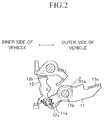
WO 2011/118356 A1 . In this connecting structure, as illustrated inFIG. 1 andFIG. 2 , a connecting leg portion (hook) 12a formed on anopen link 12 is inserted and engaged into a noncircularconnecting hole portion 11 a formed in an outsideopen lever 11, thereby connecting the outsideopen lever 11 and theopen link 12 to each other. Theopen link 12 is connected to the outsideopen lever 11 so as to be rotatable by a necessary amount along a plate surface of the outside open lever 11 (along a surface of the drawing sheet ofFIG. 2 ) under a state in which theopen link 12 is capable of swinging about a connecting region between the noncircular connectinghole portion 11 a and the connectingleg portion 12a by a predetermined amount in a thickness direction of the outside open lever 11 (direction orthogonal to the surface of the drawing sheet ofFIG. 2 ). - Note that, the outside
open lever 11 is pivotably mounted, at acircular support hole 11 b formed in an intermediate portion thereof, to asupport shaft 91a formed on ahousing body 91. In the outsideopen lever 11, aright end portion 11c illustrated inFIG. 2 serves as an input portion, whereas the above-mentioned noncircularconnecting hole portion 11a serves as an output portion. Further, the noncircular connectinghole portion 11a is formed by punching using a press. On the other hand, in theopen link 12, the above-mentioned connectingleg portion 12a serves as an input portion, whereas anupper end portion 12b illustrated inFIG. 2 serves as an output portion. Further, the connectingleg portion 12a is formed by a bending process after using a press. - Incidentally, in the structure for connecting the metal lever (outside open lever 11) and the metal link (open link 12) to each other disclosed in
WO 2011/118356 A1 , the connecting leg portion (hook) 12a formed on the metal link (12) is inserted and engaged into the noncircular connectinghole portion 11 a formed in the metal lever (11), thereby mounting the metal link to the metal lever. Accordingly, this structure is advantageous in that the structure is simple and can be manufactured at low cost. However, the connecting leg portion (hook) 12a comes off the noncircularconnecting hole portion 11 a easily at the time of assembly, and hence improvement in mountability is desired. - In order to solve the above-mentioned problem, according to the present invention, there is provided a structure for connecting a metal lever and a metal link via a metal pin, the structure including:
- a metal lever having a circular connecting hole;
- a metal pin comprising a support shaft portion, a head portion and a connecting shaft portion; and
- a metal link having a coupling hole and being integrally connected to the metal pin, the coupling hole being fitted to the connecting shaft portion.
- The support shaft portion is insertable through the connecting hole, and is pivotable and movable in an axial direction of the metal pin by a preset amount with respect to the connecting hole,
the head portion is formed at one end portion of the support shaft portion and has a diameter larger than a diameter of the support shaft portion,
the connecting shaft portion is formed at the other end portion of the support shaft portion and has a diameter smaller than the diameter of the support shaft portion, and
the metal pin comprises an allowable portion formed on at least one axial end portion of the support shaft portion of the metal pin, and the allowable portion is configured to increase an amount of swing of the metal lever on the metal pin in the axial direction of the metal pin. Note that, the above-mentioned amount of swing of the metal lever on the metal pin in the axial direction of the metal pin is a relative amount of swing. When the metal lever is incapable of swinging on the metal pin in the axial direction of the metal pin, the metal pin and the metal link swing with respect to the metal lever. - In the above-mentioned connecting structure according to the present invention, the allowable portion is formed on the at least one axial end portion of the support shaft portion of the metal pin, and is configured to increase the amount of swing of the metal lever on the metal pin in the axial direction of the metal pin. Accordingly, the amount of swing of the metal lever on the metal pin in the axial direction of the metal pin can be ensured in a necessary and sufficient manner while minimizing a radial gap between the support shaft portion of the metal pin and the connecting hole of the metal lever at an axial intermediate portion of the support shaft portion of the metal pin.
- Incidentally, in the connecting structure according to the present invention, the metal lever and the metal link are connected to each other via the metal pin, and the metal pin includes the support shaft portion pivotable and movable in the axial direction of the metal pin by the preset amount with respect to the connecting hole of the metal lever, the head portion (portion capable of preventing the metal lever from coming off the support shaft portion) being formed at one end portion of the support shaft portion and having the diameter larger than the diameter of the support shaft portion, and the connecting shaft portion (to which the metal link is integrally connected at the coupling hole after the metal lever is mounted onto the support shaft portion) being formed at the other end portion of the support shaft portion and having the diameter smaller than the diameter of the support shaft portion.
- Accordingly, under a state in which the metal lever and the metal link are connected to each other via the metal pin, the metal lever is sandwiched and retained between the metal link (connected to the connecting shaft portion of the metal pin) and the head portion of the metal pin. Therefore, under a state in which the metal lever and the metal link are connected to each other via the metal pin, the metal lever and the metal link do not easily come off the metal pin, and mountability at the time of assembly can be improved.
- When embodying the present invention, a second allowable portion (chamfered portion such as a C beveled portion or a R beveled portion (a rounded portion)) for increasing the amount of swing of the metal lever on the metal pin in the axial direction of the metal pin can be formed on at least one axial end portion of the connecting hole of the metal lever. In this case, the above-mentioned second allowable portion (chamfered portion such as a C beveled portion or a R beveled portion (a rounded portion)) can also increase the amount of swing of the metal lever on the metal pin in the axial direction of the metal pin.
- Further, when embodying the present invention, the allowable portion can be formed so that only the one axial end portion of the support shaft portion of the metal pin has a diameter smaller than that of a center portion of the support shaft portion and only the one axial end portion has a curved surface shape in radial cross-section. In this case, the amount of swing of the metal lever to the one axial end portion side can be larger than the amount of swing to the other axial end portion side. Accordingly, a large amount of swing can be set only for a direction requiring swing.
- Further, when embodying the present invention, the allowable portion can be formed so that the entire support shaft portion has a curved surface shape and a center portion of the support shaft portion of the metal pin has a maximum diameter in the support shaft portion. In this case, the amount of swing of the metal lever can be further larger than the above-mentioned case. Further, in this case, the amount of swing to the one axial end portion side and the amount of swing to the other axial end portion side can be increased equally. In this case, the allowable portion can be formed so that the support shaft portion of the metal pin has an arc shape in radial cross-section. In this case, the above-mentioned arc shape (spherical outer shape) enables the metal lever to swing more smoothly.
- Further, when embodying the present invention, the metal link or the metal lever can include a protrusion regulating a swinging direction of the metal lever to a specific direction when the metal lever swings on the metal pin in the axial direction of the metal pin. In this case, an abutment portion between the metal lever and the protrusion formed on the metal link, or an abutment portion between the metal link and the protrusion formed on the metal lever can serve as a swinging fulcrum. Accordingly, the swinging direction of the metal lever on the metal pin can be stabilized. Note that, it is desired that the above-mentioned protrusion be formed as a straight protrusion extending in a radial direction of the metal pin, and the present invention can be embodied even when the above-mentioned protrusion is formed of a point-like protrusion.
- Further, when embodying the present invention, a second allowable portion for increasing the amount of swing of the metal lever on the metal pin in the axial direction of the metal pin can be formed on the other axial end portion of the connecting hole of the metal lever. In this case, the amount of swing of the metal lever to the one axial end portion side (amount of swing in a case illustrated in
FIG. 12 described later) can be larger than the amount of swing to the other axial end portion side. Accordingly, a large amount of swing can be set only for a direction requiring swing of the metal lever. -
-
FIG. 1 is a side view for illustrating a related-art structure for connecting a metal lever and a metal link to each other (an example applied to a vehicle door lock device). -
FIG. 2 is a back view for illustrating a relationship between the metal lever (outside open lever) and the metal link (open link) illustrated inFIG. 1 . -
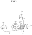
FIG. 3 is a front view for illustrating a connecting structure according to an embodiment of the present invention. -
FIG. 4 is a sectional view taken along the line 4-4 ofFIG. 3 . -
FIG. 5 is a sectional view taken along the line 5-5 ofFIG. 3 . -
FIG. 6 is a sectional view for illustrating a state in which an outside open lever illustrated inFIG. 4 is moved to a left end inFIG. 6 . -
FIG. 7 is a sectional view for illustrating a state in which an open link and a connecting pin (metal pin) swings clockwise with respect to the outside open lever illustrated inFIG. 4 . -
FIG. 8 is a sectional view for illustrating a state in which the open link and the connecting pin swings counterclockwise with respect to the outside open lever illustrated inFIG. 4 . -
FIG. 9 is a front view for illustrating a connecting structure according to another embodiment of the present invention. -
FIG. 10 is a sectional view corresponding toFIG. 4 , for illustrating the embodiment illustrated inFIG. 9 . -
FIG. 11 is a sectional view corresponding toFIG. 6 , for illustrating the embodiment illustrated inFIG. 9 . -
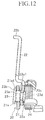
FIG. 12 is a sectional view corresponding toFIG. 7 , for illustrating the embodiment illustrated inFIG. 9 . - An embodiment of the present invention will be discussed with reference to the drawings.
FIG. 3 to FIG. 8 are illustrations of a connecting structure according to an embodiment of the present invention, which is used as a component of a vehicle door lock device. In a connectingstructure 20 according to this embodiment, an outside open lever (metal plate lever) 21 and an open link (metal plate link) 22 are connected to each other via (by) ametal connecting pin 23. Further, in the connectingstructure 20, atorsion spring 24 is interposed between the outsideopen lever 21 and theopen link 22, and theopen link 22 is biased so that theopen link 22 rotates clockwise inFIG. 3 and swings clockwise inFIG. 4 with respect to the outsideopen lever 21. - The outside
open lever 21 has a circular connectinghole 21 a (seeFIG. 4 ) formed in a distal end portion thereof, and has acircular support hole 21b (seeFIG. 3 ) formed in an intermediate portion thereof. Similarly to the outside open lever of the related art, the outsideopen lever 21 is configured so as to be pivotably mounted at thecircular support hole 21 b to a support shaft (not shown) of a housing body (not shown). Aleft end portion 21 c of the outsideopen lever 21 illustrated inFIG. 3 serves as an input portion, whereas a region of the outsideopen lever 21, in which the above-mentioned circular connectinghole 21 a is formed, serves as an output portion. Note that, at least an operation force of an outside handle, which is arranged on an outer side of a door of a vehicle, is input to theleft end portion 21 c. As a matter of course, an operation force of an inside handle, which is arranged on an inner side of the door of the vehicle, can be input to theleft end portion 21 c. - The
open link 22 includes a region, which has acircular coupling hole 22a formed in a lower end portion thereof illustrated inFIG. 3 , serves as an input portion, whereas anupper end portion 22b of theopen link 22 illustrated inFIG. 3 serves as an output portion. Thecoupling hole 22a of theopen link 22 is fitted into the connectingpin 23, and is integrally connected to the connectingpin 23. Further, theopen link 22 includes a pair ofstraight protrusions 22c extending in a radial direction (horizontal direction inFIG. 3 ) of the connectingpin 23. Each of thestraight protrusions 22c is configured to regulate a swinging direction of the outsideopen lever 21 to a specific direction (lateral direction in illustrations ofFIG. 7 andFIG. 8 ) when the outsideopen lever 21 swings on the connectingpin 23 in an axial direction (seeFIG. 7 andFIG. 8 ). When theopen link 22 and the connectingpin 23 swing with respect to the outsideopen lever 21 as illustrated inFIG. 7 andFIG. 8 , an abutment portion between the outsideopen lever 21 and eachstraight protrusion 22c formed on theopen link 22 serves as a swinging fulcrum. Eachstraight protrusion 22c is formed by press working when theopen link 22 is produced by press working. Note that, theupper end portion 22b outputs an input operation force to a latch mechanism which can retain the door on the vehicle body by engaging with a striker arranged on the door of the vehicle. - A
support shaft portion 23a is formed in an axial intermediate region of the connectingpin 23. Ahead portion 23b is formed at one end portion (left end portion illustrated inFIG. 4 ) of thesupport shaft portion 23a, whereas a connectingshaft portion 23c and aswaging fixing portion 23d are formed at the other end portion (right end portion illustrated inFIG. 4 ) of thesupport shaft portion 23a. Thesupport shaft portion 23a can be inserted through the connectinghole 21 a of the outside open lever 21 (thesupport shaft portion 23a has an outer diameter smaller than an inner diameter of the connectinghole 21 a). Thesupport shaft portion 23a is pivotable and movable in the axial direction by a preset amount with respect to the connectinghole 21 a. A spherical curved surface 23a1 (a curvature of the spherical curved surface 23a1 can be set as appropriate) is formed on each axial end portion (each lateral end portion illustrated inFIG. 4 ) of thesupport shaft portion 23a. The spherical curved surface 23a1 serves as an allowable portion for increasing an amount of swing of the outsideopen lever 21 on the connectingpin 23 in the axial direction. - The
head portion 23b has a diameter larger than that of thesupport shaft portion 23a, and larger than the inner diameter of the connectinghole 21 a of the outsideopen lever 21. Each vertical end portion of thehead portion 23b illustrated inFIG. 4 is cut off by a predetermined amount so that a vertical length of thehead portion 23b inFIG. 4 is smaller than a lateral length thereof inFIG. 5 by a predetermined amount. The connectingshaft portion 23c has a diameter smaller than that of thesupport shaft portion 23a. The connectingshaft portion 23c can be inserted through the connectinghole 21 a of the outsideopen lever 21, and can be fitted into thecoupling hole 22a of theopen link 22. Theswaging fixing portion 23d has a diameter smaller than that of the connectingshaft portion 23c before theswaging fixing portion 23d is swaged. After the connectingshaft portion 23c and thesupport shaft portion 23a are inserted through the outsideopen lever 21 and theopen link 22 is fitted to the connectingshaft portion 23c, theswaging fixing portion 23d is swaged so as to have a diameter larger than that of the connectingshaft portion 23c. In this manner, theopen link 22 is prevented from coming off. - In this embodiment configured as described above, each axial end portion of the
support shaft portion 23a of the connectingpin 23 includes the allowable portion (spherical curved surfaces 23a1) for increasing the amount of swing of the outsideopen lever 21 on the connectingpin 23 in the axial direction. Accordingly, the amount of swing of the outsideopen lever 21 on the connectingpin 23 in the axial direction can be ensured in a necessary and sufficient manner while minimizing a radial gap between thesupport shaft portion 23a of the connectingpin 23 and the connectinghole 21 a of the outsideopen lever 21 at an axial intermediate portion of thesupport shaft portion 23a of the connectingpin 23. - Incidentally, in the connecting
structure 20 according to this embodiment, the outsideopen lever 21 and theopen link 22 are connected to each other via the connectingpin 23, and the connectingpin 23 includes thesupport shaft portion 23a pivotable and movable in the axial direction by the preset amount with respect to the connectinghole 21 a of the outsideopen lever 21, thehead portion 23b (portion capable of preventing the outsideopen lever 21 from coming off thesupport shaft portion 23a) being formed at one end portion of thesupport shaft portion 23a and having a diameter larger than that of thesupport shaft portion 23a, and the connectingshaft portion 23c and theswaging fixing portion 23d (to which theopen link 22 is integrally connected at thecoupling hole 22a after the outsideopen lever 21 is mounted to thesupport shaft portion 23a) formed at the other end portion of thesupport shaft portion 23a. - Accordingly, under a state in which the outside
open lever 21 and theopen link 22 are connected to each other via the connectingpin 23, the outsideopen lever 21 is sandwiched and retained between theopen link 22 and thehead portion 23b of the connectingpin 23. Therefore, under a state in which the outsideopen lever 21 and theopen link 22 are connected to each other via the connectingpin 23, the outsideopen lever 21 and theopen link 22 do not easily come off the connectingpin 23, and hence mountability at the time of assembly can be improved. - Further, in the connecting
structure 20 according to this embodiment, thesupport shaft portion 23a of the connectingpin 23 insertable through the connectinghole 21 a of the outsideopen lever 21, and the connectingshaft portion 23c of the connectingpin 23 fitted into thecoupling hole 22a of theopen link 22 to be connected to theopen link 22 can be produced by machining with high accuracy. Thus, the radial gap between thesupport shaft portion 23a of the connectingpin 23 and the connectinghole 21 a of the outsideopen lever 21 can be produced with high accuracy. Furthermore an axial gap between the outsideopen lever 21, which is sandwiched and retained between theopen link 22 and thehead portion 23b of the connectingpin 23, and theopen link 22, and an axial gap between the outsideopen lever 21 and thehead portion 23b can be produced with high accuracy. As a result, improvement in accuracy can be achieved. - Further, in the connecting
structure 20 according to this embodiment, theopen link 22 includes thestraight protrusions 22c for regulating the swinging direction of the outsideopen lever 21 to the specific direction when the outsideopen lever 21 swings on the connectingpin 23 in the axial direction. Thus, the abutment portion between the outsideopen lever 21 and each of thestraight protrusions 22c formed on theopen link 22 can be set as the swinging fulcrum, and the swinging direction of the outsideopen lever 21 on the connectingpin 23 can be stabilized. Further, in the connectingstructure 20 according to this embodiment, thesupport shaft portion 23a of the connectingpin 23 is formed into an arc shape in radial cross-section (spherical outer shape). Accordingly, the outsideopen lever 21 can be smoothly swung on the connectingpin 23. - Note that, the connecting
structure 20 illustrated inFIG. 3 to FIG. 8 is obtained by adopting thestraight protrusions 22c as a protrusion for regulating the swinging direction of the outsideopen lever 21 to the specific direction when the outsideopen lever 21 swings on the connectingpin 23 in the axial direction. However, the protrusion can be a point-like protrusion. Further, in the connectingstructure 20 illustrated inFIG. 3 to FIG. 8 , theopen link 22 includes thestraight protrusions 22c. However, when embodying the present invention, a protrusion (protrusion capable of abutting on the open link 22) corresponding to each of thestraight protrusions 22c can be formed on theopen link 22 side of the outsideopen lever 21. - In the above-mentioned embodiment, the connecting
pin 23 includes the connectingshaft portion 23c and theswaging fixing portion 23d. However, when theopen link 22 can be firmly fitted and fixed onto the connectingshaft portion 23c of the connectingpin 23, theswaging fixing portion 23d can be omitted. Further, in the above-mentioned embodiment, the spherical curved surfaces 23a1 serving as the allowable portion are formed on each axial end portion of thesupport shaft portion 23a of the connectingpin 23. However, as in a case of another embodiment illustrated inFIG. 9 to FIG. 12 , the spherical curved surface 23a1 serving as the allowable portion can be formed on one axial end portion (right end portion illustrated inFIG. 10 ) of thesupport shaft portion 23a of the connectingpin 23, and a chamfered portion 21a1 (C beveled portion or R beveled portion (rounded portion)) serving as a second allowable portion for increasing the amount of swing of the outsideopen lever 21 on the connectingpin 23 in the axial direction can be formed on the other axial end portion (left end portion illustrated inFIG. 10 ) of the connectinghole 21 a of the outsideopen lever 21. In the another embodiment illustrated inFIG. 9 to FIG. 12 , the amount of swing to the one axial end portion side (amount of swing in a case illustrated inFIG. 12 ) can be larger than the amount of swing to the other axial end portion side. Accordingly, a large amount of swing can be set only for a direction requiring swing. - Further, a configuration of the connecting
structure 20 according to the another embodiment illustrated inFIG. 9 to FIG. 12 is obtained without forming thestraight protrusions 22c on theopen link 22. The configuration of the connectingstructure 20 illustrated inFIG. 9 to FIG. 12 excluding the above-mentioned matter is substantially the same as the configuration of the connectingstructure 20 illustrated inFIG. 3 to FIG. 8 . Thus, the same configurations (components) are denoted by the same reference symbols, and description thereof is omitted. Note that, when obtaining the connectingstructure 20 illustrated inFIG. 9 to FIG. 12 , the spherical curved surface 23a1 serving as the allowable portion can be formed on the other axial end portion (left end portion illustrated inFIG. 10 ) of thesupport shaft portion 23a of the connectingpin 23, and the chamferedportion 21 a1 (C beveled portion or R beveled portion (rounded portion)) for increasing the amount of swing of the outsideopen lever 21 on the connectingpin 23 in the axial direction can be formed on one axial end portion (right end portion illustrated inFIG. 10 ) of the connectinghole 21a of the outsideopen lever 21. In this case, the amount of swing to the one axial end portion side and the amount of swing to the other axial end portion side can be increased equally. - Further, in the above-mentioned embodiments, the spherical curved surface 23a1 serves as the allowable portion (allowable portion for increasing the amount of swing of the outside
open lever 21 on the connectingpin 23 in the axial direction) formed on the connectingpin 23. However, the above-mentioned allowable portion only needs to have the radial cross-section having a curved surface shape (a curvature of the curved surface can be set as appropriate), and is not limited to the shape according to the above-mentioned embodiments. - Further, in the above-mentioned embodiments, the connecting
structure 20 according to the present invention serves as a component of the vehicle door lock device. However, the connecting structure according to the present invention can be used as a component of vehicle door locking devices (such as a vehicle closer device, a vehicle remote control device, and a vehicle door handle device) except for the vehicle door lock device, and is not limited to the configuration according to the above-mentioned embodiments.
Claims (8)
- A structure for connecting a metal lever and a metal link via a metal pin, said structure comprising:a metal lever having a circular connecting hole;a metal pin comprising a support shaft portion, a head portion and a connecting shaft portion; anda metal link having a coupling hole and being integrally connected to said metal pin, said coupling hole being fitted to said connecting shaft portion;wherein said support shaft portion is insertable through said connecting hole, and is pivotable and movable in an axial direction of said metal pin by a preset amount with respect to said connecting hole,said head portion is formed at one end portion of said support shaft portion and has a diameter larger than a diameter of said support shaft portion,said connecting shaft portion is formed at the other end portion of said support shaft portion and has a diameter smaller than said diameter of said support shaft portion, andsaid metal pin comprises an allowable portion formed on at least one axial end portion of said support shaft portion of said metal pin, and said allowable portion is configured to increase an amount of swing of said metal lever on said metal pin in said axial direction of said metal pin.
- The structure for connecting a metal lever and a metal link via a metal pin according to claim 1, said structure further comprising a second allowable portion formed on at least one axial end portion of said connecting hole of said metal lever, and said second allowable portion being configured to increase said amount of swing of said metal lever on said metal pin in said axial direction of said metal pin.
- The structure for connecting a metal lever and a metal link via a metal pin according to claim 2, wherein said second allowable portion comprises a chamfered portion.
- The structure for connecting a metal lever and a metal link via a metal pin according to any one of claims 1 to 3, wherein said allowable portion is formed so that only said one axial end portion of said support shaft portion of said metal pin has a diameter smaller than that of a center portion of said support shaft portion and only said one axial end portion has a curved surface shape in radial cross-section.
- The structure for connecting a metal lever and a metal link via a metal pin according to any one of claims 1 to 3, wherein said allowable portion is formed so that said entire support shaft portion has a curved surface shape and a center portion of said support shaft portion of said metal pin has a maximum diameter in said support shaft portion.
- The structure for connecting a metal lever and a metal link via a metal pin according to claim 5, wherein said allowable portion is formed so that said support shaft portion of said metal pin has an arc shape in radial cross-section.
- The structure for connecting a metal lever and a metal link via a metal pin according to any one of claims 1 to 6, wherein said metal link or said metal lever comprises a protrusion regulating a swinging direction of said metal lever to a specific direction when said metal lever swings on said metal pin in said axial direction of said metal pin.
- The structure for connecting a metal lever and a metal link via a metal pin according to claim 4, said structure further comprising a second allowable portion formed on the other axial end portion of said connecting hole of said metal lever, and said second allowable portion being configured to increase said amount of swing of said metal lever on said metal pin in said axial direction of said metal pin.
Applications Claiming Priority (2)
| Application Number | Priority Date | Filing Date | Title |
|---|---|---|---|
| JP2013082768A JP6076182B2 (en) | 2013-04-11 | 2013-04-11 | Connecting structure of metal lever and metal link via metal pin |
| PCT/JP2014/060420 WO2014168212A1 (en) | 2013-04-11 | 2014-04-10 | Linking structure having metal pin interposed between metal link and metal lever |
Publications (3)
| Publication Number | Publication Date |
|---|---|
| EP2985400A1 true EP2985400A1 (en) | 2016-02-17 |
| EP2985400A4 EP2985400A4 (en) | 2016-06-29 |
| EP2985400B1 EP2985400B1 (en) | 2018-08-15 |
Family
ID=51689616
Family Applications (1)
| Application Number | Title | Priority Date | Filing Date |
|---|---|---|---|
| EP14783385.9A Active EP2985400B1 (en) | 2013-04-11 | 2014-04-10 | Linking structure having metal pin interposed between metal link and metal lever |
Country Status (7)
| Country | Link |
|---|---|
| US (1) | US20160305165A1 (en) |
| EP (1) | EP2985400B1 (en) |
| JP (1) | JP6076182B2 (en) |
| CN (1) | CN105102744A (en) |
| BR (1) | BR112015025176A2 (en) |
| TW (1) | TWI554671B (en) |
| WO (1) | WO2014168212A1 (en) |
Families Citing this family (1)
| Publication number | Priority date | Publication date | Assignee | Title |
|---|---|---|---|---|
| CN115370248A (en) * | 2021-05-20 | 2022-11-22 | 开开特股份公司 | Motor vehicle door lock |
Family Cites Families (14)
| Publication number | Priority date | Publication date | Assignee | Title |
|---|---|---|---|---|
| US3371948A (en) * | 1966-02-09 | 1968-03-05 | Gen Motors Corp | Closure latch |
| JPH0442446Y2 (en) * | 1986-02-04 | 1992-10-07 | ||
| JPH0513873Y2 (en) * | 1986-03-28 | 1993-04-13 | ||
| DE4005286A1 (en) * | 1990-02-20 | 1991-08-22 | Scharwaechter Gmbh Co Kg | Pivot bolt for stay of vehicle door - has clearance controlled by washer with conical bore |
| JP3711649B2 (en) * | 1996-09-04 | 2005-11-02 | 株式会社豊田自動織機 | Wheel toe angle adjustment mechanism in a vehicle |
| EP0835976A1 (en) * | 1996-10-09 | 1998-04-15 | Gammastamp S.p.A. | A device for restraining a vehicle door in a partially or fully open position |
| JPH1137137A (en) * | 1997-07-23 | 1999-02-09 | Toyota Autom Loom Works Ltd | Mounting structure for cylinder |
| JP4061514B2 (en) * | 1998-01-29 | 2008-03-19 | アイシン精機株式会社 | Vehicle door lock device |
| JP2001049924A (en) * | 1999-08-09 | 2001-02-20 | Aisin Seiki Co Ltd | Door closer device |
| JP2006233456A (en) * | 2005-02-22 | 2006-09-07 | Aisin Seiki Co Ltd | Door lock device |
| FR2921957B1 (en) * | 2007-10-08 | 2010-02-26 | Valeo Securite Habitacle | LOCK FOR OPENING OF MOTOR VEHICLE |
| DE102009021297A1 (en) * | 2009-05-14 | 2010-11-25 | Inteva Products Europe Gmbh | Motor vehicle lock |
| JP5447860B2 (en) * | 2010-03-24 | 2014-03-19 | アイシン精機株式会社 | Vehicle door lock device |
| DE202011004407U1 (en) * | 2011-03-26 | 2012-06-27 | Kiekert Ag | Motor vehicle door lock |
-
2013
- 2013-04-11 JP JP2013082768A patent/JP6076182B2/en active Active
-
2014
- 2014-04-10 BR BR112015025176A patent/BR112015025176A2/en not_active Application Discontinuation
- 2014-04-10 EP EP14783385.9A patent/EP2985400B1/en active Active
- 2014-04-10 US US14/783,632 patent/US20160305165A1/en not_active Abandoned
- 2014-04-10 WO PCT/JP2014/060420 patent/WO2014168212A1/en not_active Ceased
- 2014-04-10 CN CN201480019818.6A patent/CN105102744A/en active Pending
- 2014-04-11 TW TW103113416A patent/TWI554671B/en active
Also Published As
| Publication number | Publication date |
|---|---|
| TW201508147A (en) | 2015-03-01 |
| CN105102744A (en) | 2015-11-25 |
| US20160305165A1 (en) | 2016-10-20 |
| BR112015025176A2 (en) | 2017-07-18 |
| WO2014168212A1 (en) | 2014-10-16 |
| TWI554671B (en) | 2016-10-21 |
| JP2014205967A (en) | 2014-10-30 |
| JP6076182B2 (en) | 2017-02-08 |
| EP2985400B1 (en) | 2018-08-15 |
| EP2985400A4 (en) | 2016-06-29 |
Similar Documents
| Publication | Publication Date | Title |
|---|---|---|
| EP2492546B1 (en) | Anti-backlash/Anti-rattle lever | |
| EP2810611B1 (en) | Bending instrument for a surgical element | |
| JP2014227758A (en) | Handle device for vehicle | |
| CN105745388A (en) | Door latch device for vehicle | |
| US20160305165A1 (en) | Structure for connecting a metal lever and a metal link via a metal pin | |
| JP2017007573A (en) | Vehicle seat slide device | |
| JP2016169524A (en) | Vehicle handle device | |
| JP5951024B2 (en) | Shift knob assembly structure | |
| JP6438204B2 (en) | Lever connector, rod holder, and vehicle handle device | |
| JP2015148295A (en) | Parking lock device for vehicle | |
| US8596428B2 (en) | Equalizer device for parking brake | |
| EP3023566A1 (en) | Diagonal draw bar structure having micro ventilation function | |
| US9708838B2 (en) | Vehicle door handle device | |
| JP6221080B2 (en) | Control shaft mounting structure | |
| JP2010084897A (en) | Joint, and joining method of joint and shaft | |
| JP2014082052A (en) | Composite operating device | |
| CN110382266B (en) | Subassembly | |
| CN212155425U (en) | connecting rod structure | |
| JP3201748U (en) | Locking tool | |
| JP2011218521A (en) | Trigger switch | |
| JP2012241462A (en) | Cylinder lock | |
| KR20190089474A (en) | steering system | |
| JP2018003500A (en) | Handle device and manufacturing method of handle device | |
| KR20160017180A (en) | apparatus for supporting release fork of clutch | |
| JP2013246225A (en) | Strap attachment metal fitting |
Legal Events
| Date | Code | Title | Description |
|---|---|---|---|
| PUAI | Public reference made under article 153(3) epc to a published international application that has entered the european phase |
Free format text: ORIGINAL CODE: 0009012 |
|
| 17P | Request for examination filed |
Effective date: 20150901 |
|
| AK | Designated contracting states |
Kind code of ref document: A1 Designated state(s): AL AT BE BG CH CY CZ DE DK EE ES FI FR GB GR HR HU IE IS IT LI LT LU LV MC MK MT NL NO PL PT RO RS SE SI SK SM TR |
|
| AX | Request for extension of the european patent |
Extension state: BA ME |
|
| A4 | Supplementary search report drawn up and despatched |
Effective date: 20160530 |
|
| RIC1 | Information provided on ipc code assigned before grant |
Ipc: E05B 77/10 20140101ALI20160523BHEP Ipc: F16C 11/06 20060101ALN20160523BHEP Ipc: E05B 79/08 20140101AFI20160523BHEP |
|
| DAX | Request for extension of the european patent (deleted) | ||
| STAA | Information on the status of an ep patent application or granted ep patent |
Free format text: STATUS: EXAMINATION IS IN PROGRESS |
|
| 17Q | First examination report despatched |
Effective date: 20171016 |
|
| GRAP | Despatch of communication of intention to grant a patent |
Free format text: ORIGINAL CODE: EPIDOSNIGR1 |
|
| STAA | Information on the status of an ep patent application or granted ep patent |
Free format text: STATUS: GRANT OF PATENT IS INTENDED |
|
| RIC1 | Information provided on ipc code assigned before grant |
Ipc: E05B 79/08 20140101AFI20180124BHEP Ipc: F16C 11/06 20060101ALN20180124BHEP Ipc: E05B 77/10 20140101ALI20180124BHEP |
|
| INTG | Intention to grant announced |
Effective date: 20180227 |
|
| GRAS | Grant fee paid |
Free format text: ORIGINAL CODE: EPIDOSNIGR3 |
|
| GRAA | (expected) grant |
Free format text: ORIGINAL CODE: 0009210 |
|
| STAA | Information on the status of an ep patent application or granted ep patent |
Free format text: STATUS: THE PATENT HAS BEEN GRANTED |
|
| AK | Designated contracting states |
Kind code of ref document: B1 Designated state(s): AL AT BE BG CH CY CZ DE DK EE ES FI FR GB GR HR HU IE IS IT LI LT LU LV MC MK MT NL NO PL PT RO RS SE SI SK SM TR |
|
| REG | Reference to a national code |
Ref country code: CH Ref legal event code: EP Ref country code: GB Ref legal event code: FG4D Ref country code: AT Ref legal event code: REF Ref document number: 1029956 Country of ref document: AT Kind code of ref document: T Effective date: 20180815 |
|
| REG | Reference to a national code |
Ref country code: IE Ref legal event code: FG4D |
|
| REG | Reference to a national code |
Ref country code: DE Ref legal event code: R096 Ref document number: 602014030521 Country of ref document: DE |
|
| REG | Reference to a national code |
Ref country code: NL Ref legal event code: MP Effective date: 20180815 |
|
| REG | Reference to a national code |
Ref country code: LT Ref legal event code: MG4D |
|
| REG | Reference to a national code |
Ref country code: AT Ref legal event code: MK05 Ref document number: 1029956 Country of ref document: AT Kind code of ref document: T Effective date: 20180815 |
|
| PG25 | Lapsed in a contracting state [announced via postgrant information from national office to epo] |
Ref country code: NL Free format text: LAPSE BECAUSE OF FAILURE TO SUBMIT A TRANSLATION OF THE DESCRIPTION OR TO PAY THE FEE WITHIN THE PRESCRIBED TIME-LIMIT Effective date: 20180815 Ref country code: BG Free format text: LAPSE BECAUSE OF FAILURE TO SUBMIT A TRANSLATION OF THE DESCRIPTION OR TO PAY THE FEE WITHIN THE PRESCRIBED TIME-LIMIT Effective date: 20181115 Ref country code: LT Free format text: LAPSE BECAUSE OF FAILURE TO SUBMIT A TRANSLATION OF THE DESCRIPTION OR TO PAY THE FEE WITHIN THE PRESCRIBED TIME-LIMIT Effective date: 20180815 Ref country code: AT Free format text: LAPSE BECAUSE OF FAILURE TO SUBMIT A TRANSLATION OF THE DESCRIPTION OR TO PAY THE FEE WITHIN THE PRESCRIBED TIME-LIMIT Effective date: 20180815 Ref country code: IS Free format text: LAPSE BECAUSE OF FAILURE TO SUBMIT A TRANSLATION OF THE DESCRIPTION OR TO PAY THE FEE WITHIN THE PRESCRIBED TIME-LIMIT Effective date: 20181215 Ref country code: SE Free format text: LAPSE BECAUSE OF FAILURE TO SUBMIT A TRANSLATION OF THE DESCRIPTION OR TO PAY THE FEE WITHIN THE PRESCRIBED TIME-LIMIT Effective date: 20180815 Ref country code: NO Free format text: LAPSE BECAUSE OF FAILURE TO SUBMIT A TRANSLATION OF THE DESCRIPTION OR TO PAY THE FEE WITHIN THE PRESCRIBED TIME-LIMIT Effective date: 20181115 Ref country code: GR Free format text: LAPSE BECAUSE OF FAILURE TO SUBMIT A TRANSLATION OF THE DESCRIPTION OR TO PAY THE FEE WITHIN THE PRESCRIBED TIME-LIMIT Effective date: 20181116 Ref country code: RS Free format text: LAPSE BECAUSE OF FAILURE TO SUBMIT A TRANSLATION OF THE DESCRIPTION OR TO PAY THE FEE WITHIN THE PRESCRIBED TIME-LIMIT Effective date: 20180815 Ref country code: FI Free format text: LAPSE BECAUSE OF FAILURE TO SUBMIT A TRANSLATION OF THE DESCRIPTION OR TO PAY THE FEE WITHIN THE PRESCRIBED TIME-LIMIT Effective date: 20180815 |
|
| PG25 | Lapsed in a contracting state [announced via postgrant information from national office to epo] |
Ref country code: AL Free format text: LAPSE BECAUSE OF FAILURE TO SUBMIT A TRANSLATION OF THE DESCRIPTION OR TO PAY THE FEE WITHIN THE PRESCRIBED TIME-LIMIT Effective date: 20180815 Ref country code: HR Free format text: LAPSE BECAUSE OF FAILURE TO SUBMIT A TRANSLATION OF THE DESCRIPTION OR TO PAY THE FEE WITHIN THE PRESCRIBED TIME-LIMIT Effective date: 20180815 Ref country code: LV Free format text: LAPSE BECAUSE OF FAILURE TO SUBMIT A TRANSLATION OF THE DESCRIPTION OR TO PAY THE FEE WITHIN THE PRESCRIBED TIME-LIMIT Effective date: 20180815 |
|
| PG25 | Lapsed in a contracting state [announced via postgrant information from national office to epo] |
Ref country code: CZ Free format text: LAPSE BECAUSE OF FAILURE TO SUBMIT A TRANSLATION OF THE DESCRIPTION OR TO PAY THE FEE WITHIN THE PRESCRIBED TIME-LIMIT Effective date: 20180815 Ref country code: RO Free format text: LAPSE BECAUSE OF FAILURE TO SUBMIT A TRANSLATION OF THE DESCRIPTION OR TO PAY THE FEE WITHIN THE PRESCRIBED TIME-LIMIT Effective date: 20180815 Ref country code: IT Free format text: LAPSE BECAUSE OF FAILURE TO SUBMIT A TRANSLATION OF THE DESCRIPTION OR TO PAY THE FEE WITHIN THE PRESCRIBED TIME-LIMIT Effective date: 20180815 Ref country code: PL Free format text: LAPSE BECAUSE OF FAILURE TO SUBMIT A TRANSLATION OF THE DESCRIPTION OR TO PAY THE FEE WITHIN THE PRESCRIBED TIME-LIMIT Effective date: 20180815 Ref country code: EE Free format text: LAPSE BECAUSE OF FAILURE TO SUBMIT A TRANSLATION OF THE DESCRIPTION OR TO PAY THE FEE WITHIN THE PRESCRIBED TIME-LIMIT Effective date: 20180815 Ref country code: ES Free format text: LAPSE BECAUSE OF FAILURE TO SUBMIT A TRANSLATION OF THE DESCRIPTION OR TO PAY THE FEE WITHIN THE PRESCRIBED TIME-LIMIT Effective date: 20180815 |
|
| REG | Reference to a national code |
Ref country code: DE Ref legal event code: R097 Ref document number: 602014030521 Country of ref document: DE |
|
| PG25 | Lapsed in a contracting state [announced via postgrant information from national office to epo] |
Ref country code: SK Free format text: LAPSE BECAUSE OF FAILURE TO SUBMIT A TRANSLATION OF THE DESCRIPTION OR TO PAY THE FEE WITHIN THE PRESCRIBED TIME-LIMIT Effective date: 20180815 Ref country code: SM Free format text: LAPSE BECAUSE OF FAILURE TO SUBMIT A TRANSLATION OF THE DESCRIPTION OR TO PAY THE FEE WITHIN THE PRESCRIBED TIME-LIMIT Effective date: 20180815 Ref country code: DK Free format text: LAPSE BECAUSE OF FAILURE TO SUBMIT A TRANSLATION OF THE DESCRIPTION OR TO PAY THE FEE WITHIN THE PRESCRIBED TIME-LIMIT Effective date: 20180815 |
|
| PLBE | No opposition filed within time limit |
Free format text: ORIGINAL CODE: 0009261 |
|
| STAA | Information on the status of an ep patent application or granted ep patent |
Free format text: STATUS: NO OPPOSITION FILED WITHIN TIME LIMIT |
|
| 26N | No opposition filed |
Effective date: 20190516 |
|
| PG25 | Lapsed in a contracting state [announced via postgrant information from national office to epo] |
Ref country code: SI Free format text: LAPSE BECAUSE OF FAILURE TO SUBMIT A TRANSLATION OF THE DESCRIPTION OR TO PAY THE FEE WITHIN THE PRESCRIBED TIME-LIMIT Effective date: 20180815 |
|
| REG | Reference to a national code |
Ref country code: CH Ref legal event code: PL |
|
| REG | Reference to a national code |
Ref country code: BE Ref legal event code: MM Effective date: 20190430 |
|
| GBPC | Gb: european patent ceased through non-payment of renewal fee |
Effective date: 20190410 |
|
| PG25 | Lapsed in a contracting state [announced via postgrant information from national office to epo] |
Ref country code: LU Free format text: LAPSE BECAUSE OF NON-PAYMENT OF DUE FEES Effective date: 20190410 Ref country code: MC Free format text: LAPSE BECAUSE OF FAILURE TO SUBMIT A TRANSLATION OF THE DESCRIPTION OR TO PAY THE FEE WITHIN THE PRESCRIBED TIME-LIMIT Effective date: 20180815 |
|
| PG25 | Lapsed in a contracting state [announced via postgrant information from national office to epo] |
Ref country code: CH Free format text: LAPSE BECAUSE OF NON-PAYMENT OF DUE FEES Effective date: 20190430 Ref country code: GB Free format text: LAPSE BECAUSE OF NON-PAYMENT OF DUE FEES Effective date: 20190410 Ref country code: LI Free format text: LAPSE BECAUSE OF NON-PAYMENT OF DUE FEES Effective date: 20190430 |
|
| PG25 | Lapsed in a contracting state [announced via postgrant information from national office to epo] |
Ref country code: BE Free format text: LAPSE BECAUSE OF NON-PAYMENT OF DUE FEES Effective date: 20190430 |
|
| PG25 | Lapsed in a contracting state [announced via postgrant information from national office to epo] |
Ref country code: TR Free format text: LAPSE BECAUSE OF FAILURE TO SUBMIT A TRANSLATION OF THE DESCRIPTION OR TO PAY THE FEE WITHIN THE PRESCRIBED TIME-LIMIT Effective date: 20180815 |
|
| PG25 | Lapsed in a contracting state [announced via postgrant information from national office to epo] |
Ref country code: IE Free format text: LAPSE BECAUSE OF NON-PAYMENT OF DUE FEES Effective date: 20190410 |
|
| PG25 | Lapsed in a contracting state [announced via postgrant information from national office to epo] |
Ref country code: PT Free format text: LAPSE BECAUSE OF FAILURE TO SUBMIT A TRANSLATION OF THE DESCRIPTION OR TO PAY THE FEE WITHIN THE PRESCRIBED TIME-LIMIT Effective date: 20181215 |
|
| PG25 | Lapsed in a contracting state [announced via postgrant information from national office to epo] |
Ref country code: CY Free format text: LAPSE BECAUSE OF FAILURE TO SUBMIT A TRANSLATION OF THE DESCRIPTION OR TO PAY THE FEE WITHIN THE PRESCRIBED TIME-LIMIT Effective date: 20180815 |
|
| PG25 | Lapsed in a contracting state [announced via postgrant information from national office to epo] |
Ref country code: MT Free format text: LAPSE BECAUSE OF FAILURE TO SUBMIT A TRANSLATION OF THE DESCRIPTION OR TO PAY THE FEE WITHIN THE PRESCRIBED TIME-LIMIT Effective date: 20180815 Ref country code: HU Free format text: LAPSE BECAUSE OF FAILURE TO SUBMIT A TRANSLATION OF THE DESCRIPTION OR TO PAY THE FEE WITHIN THE PRESCRIBED TIME-LIMIT; INVALID AB INITIO Effective date: 20140410 |
|
| PG25 | Lapsed in a contracting state [announced via postgrant information from national office to epo] |
Ref country code: MK Free format text: LAPSE BECAUSE OF FAILURE TO SUBMIT A TRANSLATION OF THE DESCRIPTION OR TO PAY THE FEE WITHIN THE PRESCRIBED TIME-LIMIT Effective date: 20180815 |
|
| PGFP | Annual fee paid to national office [announced via postgrant information from national office to epo] |
Ref country code: DE Payment date: 20250305 Year of fee payment: 12 |
|
| PGFP | Annual fee paid to national office [announced via postgrant information from national office to epo] |
Ref country code: FR Payment date: 20260309 Year of fee payment: 13 |