EP2985200A2 - Traffic lights information processing apparatus, information processing method, and computer program for controlling the electrical power consumption in the vehicle - Google Patents
Traffic lights information processing apparatus, information processing method, and computer program for controlling the electrical power consumption in the vehicle Download PDFInfo
- Publication number
- EP2985200A2 EP2985200A2 EP15179957.4A EP15179957A EP2985200A2 EP 2985200 A2 EP2985200 A2 EP 2985200A2 EP 15179957 A EP15179957 A EP 15179957A EP 2985200 A2 EP2985200 A2 EP 2985200A2
- Authority
- EP
- European Patent Office
- Prior art keywords
- vehicle
- traffic light
- information
- electric power
- information processing
- Prior art date
- Legal status (The legal status is an assumption and is not a legal conclusion. Google has not performed a legal analysis and makes no representation as to the accuracy of the status listed.)
- Granted
Links
- 230000010365 information processing Effects 0.000 title claims abstract description 37
- 238000004590 computer program Methods 0.000 title claims description 8
- 238000003672 processing method Methods 0.000 title claims description 7
- 238000004364 calculation method Methods 0.000 claims abstract description 53
- 230000007423 decrease Effects 0.000 claims description 6
- 238000005286 illumination Methods 0.000 claims description 2
- 238000004891 communication Methods 0.000 description 51
- 238000000034 method Methods 0.000 description 24
- 238000010586 diagram Methods 0.000 description 18
- 230000008569 process Effects 0.000 description 13
- 230000006870 function Effects 0.000 description 12
- 230000004048 modification Effects 0.000 description 8
- 238000012986 modification Methods 0.000 description 8
- 238000012545 processing Methods 0.000 description 6
- 230000000694 effects Effects 0.000 description 3
- 238000005516 engineering process Methods 0.000 description 3
- 238000012546 transfer Methods 0.000 description 3
- 230000008878 coupling Effects 0.000 description 2
- 238000010168 coupling process Methods 0.000 description 2
- 238000005859 coupling reaction Methods 0.000 description 2
- 230000005540 biological transmission Effects 0.000 description 1
- 230000008859 change Effects 0.000 description 1
- 238000010276 construction Methods 0.000 description 1
- 230000001934 delay Effects 0.000 description 1
- 230000003111 delayed effect Effects 0.000 description 1
- 239000000446 fuel Substances 0.000 description 1
- 230000007246 mechanism Effects 0.000 description 1
- 230000000007 visual effect Effects 0.000 description 1
Images


Classifications
-
- B—PERFORMING OPERATIONS; TRANSPORTING
- B60—VEHICLES IN GENERAL
- B60W—CONJOINT CONTROL OF VEHICLE SUB-UNITS OF DIFFERENT TYPE OR DIFFERENT FUNCTION; CONTROL SYSTEMS SPECIALLY ADAPTED FOR HYBRID VEHICLES; ROAD VEHICLE DRIVE CONTROL SYSTEMS FOR PURPOSES NOT RELATED TO THE CONTROL OF A PARTICULAR SUB-UNIT
- B60W50/00—Details of control systems for road vehicle drive control not related to the control of a particular sub-unit, e.g. process diagnostic or vehicle driver interfaces
- B60W50/0097—Predicting future conditions
-
- B—PERFORMING OPERATIONS; TRANSPORTING
- B60—VEHICLES IN GENERAL
- B60W—CONJOINT CONTROL OF VEHICLE SUB-UNITS OF DIFFERENT TYPE OR DIFFERENT FUNCTION; CONTROL SYSTEMS SPECIALLY ADAPTED FOR HYBRID VEHICLES; ROAD VEHICLE DRIVE CONTROL SYSTEMS FOR PURPOSES NOT RELATED TO THE CONTROL OF A PARTICULAR SUB-UNIT
- B60W10/00—Conjoint control of vehicle sub-units of different type or different function
- B60W10/04—Conjoint control of vehicle sub-units of different type or different function including control of propulsion units
-
- B—PERFORMING OPERATIONS; TRANSPORTING
- B60—VEHICLES IN GENERAL
- B60W—CONJOINT CONTROL OF VEHICLE SUB-UNITS OF DIFFERENT TYPE OR DIFFERENT FUNCTION; CONTROL SYSTEMS SPECIALLY ADAPTED FOR HYBRID VEHICLES; ROAD VEHICLE DRIVE CONTROL SYSTEMS FOR PURPOSES NOT RELATED TO THE CONTROL OF A PARTICULAR SUB-UNIT
- B60W10/00—Conjoint control of vehicle sub-units of different type or different function
- B60W10/24—Conjoint control of vehicle sub-units of different type or different function including control of energy storage means
-
- B—PERFORMING OPERATIONS; TRANSPORTING
- B60—VEHICLES IN GENERAL
- B60W—CONJOINT CONTROL OF VEHICLE SUB-UNITS OF DIFFERENT TYPE OR DIFFERENT FUNCTION; CONTROL SYSTEMS SPECIALLY ADAPTED FOR HYBRID VEHICLES; ROAD VEHICLE DRIVE CONTROL SYSTEMS FOR PURPOSES NOT RELATED TO THE CONTROL OF A PARTICULAR SUB-UNIT
- B60W10/00—Conjoint control of vehicle sub-units of different type or different function
- B60W10/30—Conjoint control of vehicle sub-units of different type or different function including control of auxiliary equipment, e.g. air-conditioning compressors or oil pumps
-
- B—PERFORMING OPERATIONS; TRANSPORTING
- B60—VEHICLES IN GENERAL
- B60W—CONJOINT CONTROL OF VEHICLE SUB-UNITS OF DIFFERENT TYPE OR DIFFERENT FUNCTION; CONTROL SYSTEMS SPECIALLY ADAPTED FOR HYBRID VEHICLES; ROAD VEHICLE DRIVE CONTROL SYSTEMS FOR PURPOSES NOT RELATED TO THE CONTROL OF A PARTICULAR SUB-UNIT
- B60W30/00—Purposes of road vehicle drive control systems not related to the control of a particular sub-unit, e.g. of systems using conjoint control of vehicle sub-units, or advanced driver assistance systems for ensuring comfort, stability and safety or drive control systems for propelling or retarding the vehicle
- B60W30/18—Propelling the vehicle
- B60W30/18009—Propelling the vehicle related to particular drive situations
- B60W30/18027—Drive off, accelerating from standstill
-
- B—PERFORMING OPERATIONS; TRANSPORTING
- B60—VEHICLES IN GENERAL
- B60W—CONJOINT CONTROL OF VEHICLE SUB-UNITS OF DIFFERENT TYPE OR DIFFERENT FUNCTION; CONTROL SYSTEMS SPECIALLY ADAPTED FOR HYBRID VEHICLES; ROAD VEHICLE DRIVE CONTROL SYSTEMS FOR PURPOSES NOT RELATED TO THE CONTROL OF A PARTICULAR SUB-UNIT
- B60W30/00—Purposes of road vehicle drive control systems not related to the control of a particular sub-unit, e.g. of systems using conjoint control of vehicle sub-units, or advanced driver assistance systems for ensuring comfort, stability and safety or drive control systems for propelling or retarding the vehicle
- B60W30/18—Propelling the vehicle
- B60W30/18009—Propelling the vehicle related to particular drive situations
- B60W30/18054—Propelling the vehicle related to particular drive situations at stand still, e.g. engine in idling state
-
- B—PERFORMING OPERATIONS; TRANSPORTING
- B60—VEHICLES IN GENERAL
- B60W—CONJOINT CONTROL OF VEHICLE SUB-UNITS OF DIFFERENT TYPE OR DIFFERENT FUNCTION; CONTROL SYSTEMS SPECIALLY ADAPTED FOR HYBRID VEHICLES; ROAD VEHICLE DRIVE CONTROL SYSTEMS FOR PURPOSES NOT RELATED TO THE CONTROL OF A PARTICULAR SUB-UNIT
- B60W30/00—Purposes of road vehicle drive control systems not related to the control of a particular sub-unit, e.g. of systems using conjoint control of vehicle sub-units, or advanced driver assistance systems for ensuring comfort, stability and safety or drive control systems for propelling or retarding the vehicle
- B60W30/18—Propelling the vehicle
- B60W30/188—Controlling power parameters of the driveline, e.g. determining the required power
- B60W30/1886—Controlling power supply to auxiliary devices
-
- B—PERFORMING OPERATIONS; TRANSPORTING
- B60—VEHICLES IN GENERAL
- B60W—CONJOINT CONTROL OF VEHICLE SUB-UNITS OF DIFFERENT TYPE OR DIFFERENT FUNCTION; CONTROL SYSTEMS SPECIALLY ADAPTED FOR HYBRID VEHICLES; ROAD VEHICLE DRIVE CONTROL SYSTEMS FOR PURPOSES NOT RELATED TO THE CONTROL OF A PARTICULAR SUB-UNIT
- B60W40/00—Estimation or calculation of non-directly measurable driving parameters for road vehicle drive control systems not related to the control of a particular sub unit, e.g. by using mathematical models
- B60W40/02—Estimation or calculation of non-directly measurable driving parameters for road vehicle drive control systems not related to the control of a particular sub unit, e.g. by using mathematical models related to ambient conditions
- B60W40/04—Traffic conditions
-
- B—PERFORMING OPERATIONS; TRANSPORTING
- B60—VEHICLES IN GENERAL
- B60W—CONJOINT CONTROL OF VEHICLE SUB-UNITS OF DIFFERENT TYPE OR DIFFERENT FUNCTION; CONTROL SYSTEMS SPECIALLY ADAPTED FOR HYBRID VEHICLES; ROAD VEHICLE DRIVE CONTROL SYSTEMS FOR PURPOSES NOT RELATED TO THE CONTROL OF A PARTICULAR SUB-UNIT
- B60W2400/00—Indexing codes relating to detected, measured or calculated conditions or factors
-
- B—PERFORMING OPERATIONS; TRANSPORTING
- B60—VEHICLES IN GENERAL
- B60W—CONJOINT CONTROL OF VEHICLE SUB-UNITS OF DIFFERENT TYPE OR DIFFERENT FUNCTION; CONTROL SYSTEMS SPECIALLY ADAPTED FOR HYBRID VEHICLES; ROAD VEHICLE DRIVE CONTROL SYSTEMS FOR PURPOSES NOT RELATED TO THE CONTROL OF A PARTICULAR SUB-UNIT
- B60W2554/00—Input parameters relating to objects
-
- B—PERFORMING OPERATIONS; TRANSPORTING
- B60—VEHICLES IN GENERAL
- B60W—CONJOINT CONTROL OF VEHICLE SUB-UNITS OF DIFFERENT TYPE OR DIFFERENT FUNCTION; CONTROL SYSTEMS SPECIALLY ADAPTED FOR HYBRID VEHICLES; ROAD VEHICLE DRIVE CONTROL SYSTEMS FOR PURPOSES NOT RELATED TO THE CONTROL OF A PARTICULAR SUB-UNIT
- B60W2555/00—Input parameters relating to exterior conditions, not covered by groups B60W2552/00, B60W2554/00
- B60W2555/60—Traffic rules, e.g. speed limits or right of way
-
- B—PERFORMING OPERATIONS; TRANSPORTING
- B60—VEHICLES IN GENERAL
- B60W—CONJOINT CONTROL OF VEHICLE SUB-UNITS OF DIFFERENT TYPE OR DIFFERENT FUNCTION; CONTROL SYSTEMS SPECIALLY ADAPTED FOR HYBRID VEHICLES; ROAD VEHICLE DRIVE CONTROL SYSTEMS FOR PURPOSES NOT RELATED TO THE CONTROL OF A PARTICULAR SUB-UNIT
- B60W2710/00—Output or target parameters relating to a particular sub-units
- B60W2710/30—Auxiliary equipments
Definitions
- the present invention relates to an information processing apparatus, an information processing method, and a computer program product.
- Some energy saving systems can be provided to a vehicle (including onboard equipment) stopping at the red signal.
- a vehicle including onboard equipment
- Japanese Patent Application Laid-open No. 2012-3351 discloses a conventional technology with which a vehicle receives packets including information related to a duration time of lighting. If the color of the light indicates red and if the value of the duration time of lighting is larger than a threshold, control is performed to stop the engine.
- An information processing apparatus is mounted on a vehicle.
- the information processing apparatus includes: a first acquiring unit that acquires, from each of one or more traffic lights, traffic light information including identifying information for identifying a corresponding traffic light, position information of the corresponding traffic light, and start time and end time of lighting in a color of a traffic signal indicating stop of the vehicle; a calculation unit that calculates a signal waiting time that indicates a time period for the vehicle to stop at a traffic light by using one or more pieces of the traffic light information; and an electric power control unit that controls an electric power state during stop of the vehicle in a multistage manner in accordance with the signal waiting time.
- An information processing method is executed by an information processing apparatus mounted on a vehicle.
- the information processing method includes: first acquiring, from each of one or more traffic lights, traffic light information including identifying information for identifying a corresponding traffic light, position information of the corresponding traffic light, and start time and end time of lighting in a color of a traffic signal indicating stop of the vehicle; calculating a signal waiting time that indicates a time period for the vehicle to stop at the traffic light by using one or more pieces of the traffic light information; and controlling an electric power state during stop of the vehicle in a multistage manner in accordance with the signal waiting time.
- a computer program product includes a non-transitory computer-readable medium containing an information processing program.
- the program causes a computer mounted on a vehicle to execute: first acquiring, from one or more traffic lights, traffic light information including identifying information for identifying the traffic lights, position information of the traffic lights, and start times and end times of lighting in a color of a traffic signal indicating stop of the vehicle; calculating a signal waiting time that indicates a time period for the vehicle to stop at the traffic light by using one or more pieces of the traffic light information; and controlling an electric power state during stop of the vehicle in a multistage manner in accordance with the signal waiting time.
- vehicle refers to an object capable of running on a road, including cars and motorbikes.
- vehicles include a diesel vehicle, a fuel cell electric vehicle, a hybrid vehicle, and an electric vehicle.
- FIG. 1 is a diagram illustrating an example of the configuration of an electronic control unit (ECU) in a vehicle according to a first embodiment of the present invention.
- the example illustrated in FIG. 1 includes a plurality of (three in the example illustrated in FIG. 1 ) domains (control systems), each including a plurality of ECUs (1, 2, and 3).
- Each of the domains integrally controls a plurality of ECUs belonging to the corresponding domain and is coupled to a communication apparatus 10 externally communicating with a device and the like.
- the example illustrated in FIG. 1 includes three domains, out of which a first domain includes an ECU 1, an ECU 4, and an ECU 5.
- the ECU 1 integrally controls the ECU 4 and the ECU 5 and is coupled to the communication apparatus 10.
- a second domain includes an ECU 2, an ECU 6, and an ECU 7.
- the ECU 2 integrally controls the ECU 6 and the ECU 7 and is coupled to the communication apparatus 10.
- a third domain includes an ECU 3, an ECU 8, and an ECU 9.
- the ECU 3 integrally controls the ECU 8 and the ECU 9 and is coupled to the communication apparatus 10.
- FIG. 1 illustrates the three domains
- the number and types of domains may be changed optionally.
- the domains include an infotainment system (a control system including an audio visual system, a car navigation, and an electronic toll collection (ETC) system, for example), a body system (a control system including meters, a vehicle air-conditioner, and windows, for example), a power train system (a control system including an engine and a transmission, for example), and a chassis system (a control system including a brake, a steering, and a collision avoidance mechanism, for example).
- ETC electronic toll collection
- An on-board diagnostics system notifies a driver of a fault point in the vehicle.
- OBD types include, but are not limited to, OBD-I and OBD-II, out of which OBD-II is adopted in this example.
- An OBD port 20 illustrated in FIG. 1 is an interface for coupling the system (OBD) and the communication apparatus 10 to each other.
- the configuration of the ECU in the vehicle is not limited to the configuration illustrated in FIG. 1 , and other various ECU configurations may be adopted.
- the domains each may include a communication apparatus, for example.
- an ECU configuration in a vehicle may be included in an advanced driver assistance system (ADAS), for example.
- ADAS advanced driver assistance system
- FIG. 2 is a diagram illustrating an example of the configuration of the communication apparatus 10.
- the communication apparatus 10 includes a communication unit 11, a storage unit 12, a control unit 13, a timer 14, and an input/output unit 15.
- the communication unit 11 communicates with an external device outside of the vehicle (e.g., a later-described traffic light 30, intelligent transport systems (ITS), or other external systems).
- the storage unit 12 stores various types of information such as information required for transmitting and receiving packets.
- the control unit 13 integrally controls entire operations of the communication apparatus 10 and is constituted by a CPU in this example.
- the timer 14 measures time.
- the input/output unit 15 exchanges information in the vehicle.
- the communication unit 11, the control unit 13, and the timer 14 may be implemented with software or hardware.
- the CPU executing software processing during communication processing can execute other processing. If no processing is required, the CPU can shift to the energy saving mode.
- the storage unit 12 may be a USB memory, an SD memory, a RAM, and the like, as long as they can store packets therein.
- the storage unit 12 needs to include a reading function and a writing function.
- FIG. 3 is a diagram illustrating an example of the configuration of a traffic light 30 installed on a road.
- the traffic light 30 includes a communication unit 31, a storage unit 32, a control unit 33, a timer 34, an input/output unit 35, and a lighting unit 36.
- the communication unit 31 communicates with an external device out of the traffic light 30 (e.g., the communication apparatus 10 of the vehicle).
- the storage unit 32 stores therein various types of information such as information required for transmitting and receiving packets.
- the control unit 33 integrally controls entire operations of the traffic light 30 and is constituted by a CPU in this example.
- the timer 34 measures time.
- the input/output unit 35 exchanges information in the traffic light 30 and functions as a unit for coupling the control unit 33 to the lighting unit 36, for example.
- the lighting unit 36 lights up traffic signals such as a red signal indicating stop of the vehicle and the green signal permitting advance of the vehicle.
- the communication unit 31, the control unit 33, and the timer 34 may be implemented with software or hardware. In hardware implementation, the CPU executing software processing during communication processing can execute other processing. If no processing is required, the CPU can shift to the energy saving mode.
- the storage unit 32 may be a USB memory, an SD memory, a RAM, and the like, as long as they can store packets therein. The storage unit 32 needs to include a reading function and a writing function.
- the traffic light 30 periodically broadcasts packets including information of the traffic light 30 (traffic light information).
- the traffic light information includes at least an IP address, position information of the traffic light 30, and start time and end time of lighting in a color of the traffic signal indicating stop of the vehicle (red in this example).
- the IP address may be global IPv4 or IPv6 and is used for identifying the individual traffic light 30.
- the start time of lighting in the color of the traffic signal indicating stop of the vehicle may be hereinafter referred to as "start time of the red signal”.
- the end time of lighting in the color of the traffic signal indicating stop of the vehicle may be hereinafter referred to as "end time of the red signal”.
- the IP address can be considered to correspond to "identifying information" in claims herein, but is not limited thereto.
- the broadcast packets include the start time and the end time of the present red signal. If the traffic light 30 indicates the green signal, the broadcast packets include the start time and the end time of the next red signal.
- the control unit 33 of the traffic light 30 monitors the timer 34 and generates packets to be broadcast at regular intervals (the value of the interval may be set in a register in the control unit 33). The control unit 33 then stores the generated packets in the storage unit 32. Subsequently, the control unit 33 passes a head address in a queue in a storage area in the storage unit 32 as the minimum information to the communication unit 31.
- the communication unit 31 broadcasts the packets to the outside of the traffic light 30.
- the configuration and operation for passing the head address in a queue are not necessarily limited to those described above.
- color indicating stop of the vehicle typically refers to the color indicating stop of the straight running of the vehicle.
- FIG. 4 is a diagram illustrating an example of the functional configuration of the communication apparatus 10.
- the communication apparatus 10 may include other functions.
- the communication apparatus 10 includes a time source acquiring unit 101, a first acquiring unit 102, a calculation unit 103, and an electric power control unit 104. These functions and units are achieved with any one of the components illustrated in FIG. 2 operating by a command from the CPU of the communication apparatus 10.
- the communication apparatus 10 can be considered to correspond to an "information processing apparatus" in claims herein, but is not limited thereto.
- the whole configuration of the ECU of the vehicle (the whole configuration illustrated in FIG. 1 ) can also be considered to correspond to the "information processing apparatus" in claims herein. In short, any configuration is acceptable, as long as the information processing apparatus including at least the functions illustrated in FIG. 4 are mounted on a vehicle.
- the time source acquiring unit 101 acquires time source.
- the time source can be acquired from a global positioning system (GPS) satellite or a code division multiple access (CDMA) mobile-phone base station.
- GPS global positioning system
- CDMA code division multiple access
- the traffic light 30 also acquires time source in the same manner, thereby synchronizing time between the traffic light 30 and the vehicle.
- the first acquiring unit 102 acquires, from one or more traffic lights 30, traffic light information including IP addresses for identifying the traffic lights 30, position information of the traffic lights 30, and start times and end times of the red signal. In the present embodiment, the first acquiring unit 102 receives (acquires), from one or more traffic lights 30, the above-described packets to be periodically broadcast.
- the calculation unit 103 calculates the signal waiting time that indicates a time period for the own vehicle to stop at the traffic light 30 by using one or more pieces of the traffic light information acquired by the first acquiring unit 102. More specifically, the calculation unit 103 calculates the signal waiting time by using predicted time of arrival and the traffic light information acquired from the nearest traffic light. The predicted time of arrival indicates predicted time for the own vehicle to arrive at the nearest traffic light. In addition, the calculation unit 103 identifies the nearest traffic light 30 existing in the advance direction of the own vehicle based on navigation information indicating the position information of a plurality of traffic lights 30 and the respective IP addresses, and the advance direction of the own vehicle.
- the calculation unit 103 calculates the signal waiting time by using the traffic light information including the IP address of the identified traffic light 30 out of the one or more pieces of the traffic light information acquired by the first acquiring unit 101.
- the navigation information typically indicates the position of the own vehicle on geographic information prepared in advance. In this example, the navigation information also includes the IP addresses of the traffic lights 30 existing on the geographic information.
- the communication unit 11 of the communication apparatus 10 receives packets broadcast from the traffic light 30 and stores them in the storage unit 12.
- the communication unit 11 passes the head address in a queue in the storage area in the storage unit 12 as the minimum information to the control unit 13.
- the control unit 13 transfers the source IP address of the broadcast packets to the ECU controlling the car navigation.
- the configuration and operation for passing the head address in a queue are not necessarily limited thereto.
- the ECU controlling the car navigation compares the IP address of the traffic light 30 in the navigation information stored in advance in the ECU with the source IP address of the broadcast packets.
- the ECU controlling the car navigation thus can identify the traffic light 30 from which the packets are transmitted.
- the control unit 13 may transfer the position information of the traffic light 30 in the traffic light information included in the broadcast packets to the ECU controlling the car navigation.
- the ECU controlling the car navigation compares the position information of the traffic light 30 in the navigation information stored in advance in the ECU with the position information transferred from the control unit 13.
- the ECU controlling the car navigation thus can identify the traffic light 30 corresponding to the position information transferred from the control unit 13.
- the ECU controlling the car navigation identifies, under the instruction of the control unit 13, the nearest traffic light 30 existing in the advance direction of the own vehicle out of the one or more traffic lights 30 that each have broadcast packets.
- the ECU controlling the car navigation uses the packets from the identified traffic light 30 (hereinafter also referred to as "targeted traffic light 30") to calculate the above-described signal waiting time. While the ECU controlling the car navigation can identify (estimate) the advance direction of the own vehicle based on the route to the destination and the present position of the own vehicle, for example, the method for identifying the advance direction of the own vehicle is optional and not limited thereto.
- the packets transmitted from the targeted traffic light 30 include the IP address of the targeted traffic light 30, the position information of the targeted traffic light 30, the start time and the end time of the red signal.
- the ECU controlling the car navigation can calculate the signal waiting time by using these pieces of information.
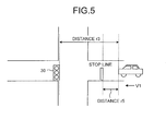
- the distance from the present position of the own vehicle to the stop line of the targeted traffic light 30 is determined as r5
- the speed of the own vehicle is determined as v1
- the start time of the red signal is determined as t1
- the end time of the red signal is determined as t2
- the present time is determined as t3, for example.
- the distance r5 can be calculated by using the above-described navigation information, for example.
- the speed v1 may be detected by the ECU controlling the car navigation or acquired from another ECU.
- the signal waiting time is calculated as t2 - t4.
- the own vehicle is determined not to stop at (to pass through) the targeted traffic light 30.
- the signal waiting time is calculated as t2 - t4.
- the above-described threshold may be variably set depending on information indicating the congestion on the road, for example. If the own vehicle does not stop at the targeted traffic light 30, no signal waiting time occurs; therefore, the signal waiting time is not calculated.
- the ECU controlling the car navigation can determine whether the own vehicle stops at the nearest traffic light 30 and also calculate the signal waiting time by using the traffic light information (e.g., an IP address) included in the packets transmitted from the targeted traffic light 30 and the predicted time of arrival t4.
- the predicted time of arrival t4 may be calculated by the ECU controlling the car navigation, or may be calculated by another ECU, from which the ECU controlling the car navigation receives the calculation result.
- the calculation method of the predicted time of arrival t4 is optional and not limited to the above-described method.
- the predicted time of arrival t4 may be calculated by taking into account the distance r3 from the vehicle (own vehicle) to the targeted traffic light 30 illustrated in FIG. 5 .
- the predicted time of arrival t4 may be calculated by taking into account the information indicating the congestion on the road that can be acquired from the ITS or other external systems.
- the ECU controlling the car navigation notifies the control unit 13 of the signal waiting time calculated as described above.
- the control unit 13 instructs the ECU controlling the car navigation to calculate the signal waiting time and receives the result.
- the calculation unit 103 calculates the signal waiting time that indicates a time period for the vehicle to stop at the traffic light 30 by using one or more pieces of the traffic light information acquired by the first acquiring unit 102".
- the control unit 13 may receive the information required for calculating the signal waiting time (e.g., the above-described navigation information) from the ECU controlling the car navigation and calculate the signal waiting time based on the received information, for example.
- the electric power control unit 104 controls the electric power state of the own vehicle during stop of the own vehicle in a multistage manner in accordance with the signal waiting time calculated by the calculation unit 103. More specifically, the electric power control unit 104 performs control so that the power consumption during stop of the own vehicle decreases with an increase in the signal waiting time. For example, if the signal waiting time exceeds a first threshold and is equal to or smaller than a second threshold that is larger than the first threshold, the electric power control unit 104 controls the idling speed of the engine to the speed lower than the idling speed of when the signal waiting time equal to or smaller than the first threshold.
- the electric power control unit 104 can control the engine to stop.
- the electric power control unit 104 can perform control so that the amount of light of an illumination device provided to the own vehicle (typically a headlight) decreases with an increase in the signal waiting time.
- the electric power state during stop of the own vehicle is the energy saving state (hereinafter also referred to as "energy saving mode”) with smaller power consumption than the normal state (hereinafter also referred to as "normal mode”) indicating the electric power state while the own vehicle is running. If no other vehicle exists between the nearest traffic light 30 (the targeted traffic light 30) and the own vehicle during stop of the own vehicle, the electric power control unit 104 performs control so as to cancel the energy saving state a prescribed time period before the end of the signal waiting time.
- the prescribed time period preferably indicates a time period required for the own vehicle to return from the energy saving state to the normal state.
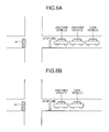
- the electric power control unit 104 changes the prescribed time period depending on the number of other vehicles. More specifically, if any other vehicle exists between the nearest traffic light 30 and the own vehicle during stop of the own vehicle, the electric power control unit 104 changes the prescribed time period so that the time period decreases with an increase in the number of other vehicles. For example, in FIG. 6A , during stop of the own vehicle, the number of other vehicles existing between the nearest traffic light 30 and the own vehicle is "2". In FIG. 6B , during stop of the own vehicle, the number of other vehicles existing between the nearest traffic light 30 and the own vehicle is "1". On this occasion, the prescribed time period in FIG.
- the electric power control unit 104 may perform control so as to cancel the energy saving state a prescribed time period after the end of the signal waiting time depending on the number of other vehicles existing between the nearest traffic light 30 and the own vehicle. Increased number of other vehicles existing between the nearest traffic light 30 and the own vehicle delays the start of running the own vehicle. Taking this into account, the control to cancel the energy saving state is delayed, thereby acquiring more advantageous effects of energy saving.
- the method for determining whether any other vehicle exists between the nearest traffic light 30 and the own vehicle is optional.
- the communication apparatus 10 acquires, from another vehicle, vehicle position information indicating the position of the other vehicle (acquires in a certain cycle, for example). Based on the acquired vehicle position information and the above-described navigation information, the communication apparatus 10 can determine whether any other vehicle exists between the nearest traffic light 30 and the own vehicle. If any other vehicle exists between the nearest traffic light 30 and the own vehicle, the communication apparatus 10 can detect the number of other vehicles.
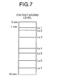
- FIG. 7 is a diagram for explaining that the electric power control unit 104 selects the energy saving level during stop of the own vehicle in accordance with the signal waiting time calculated by the calculation unit 103.
- the ordinate axis on the left side in FIG. 7 represents the signal waiting time (in the example illustrated in FIG. 7 , ranging from 0 to 10 minutes).
- the ordinate axis on the right side in FIG. 7 represents the energy saving level depending on the signal waiting time.
- the correspondence information (the correspondence table) indicating the corresponding relation between the signal waiting time and the energy saving level is stored in the storage unit 12 illustrated in FIG. 2 , for example, the destination of the correspondence information is optional and the information may be stored in an external device, for example.
- the correspondence information may be set by a car mechanic through the OBD port 20 at the factory shipment or during replacement of devices, for example.
- the correspondence information is displayed on a display (on the screen of the car navigation, the screen provided on the windshield, or the screen of a terminal installed on the own vehicle), for example.
- the correspondence information can be variably set through an input operation by a driver to the displayed correspondence information.
- a command corresponding to the user operation is interpreted by an ECU controlling the display.
- a control command corresponding to the interpretation result is transferred to an ECU controlling the correspondence information.
- the ECU controlling the correspondence information rewrites the correspondence information in accordance with the received control command.
- the energy saving level "1" is adopted if the signal waiting time ranges from 0 minutes to 1 minute.
- the level setting may be defined depending on the model of the vehicle or depending on the owner of the vehicle.
- the energy saving level 1 may be set so as not to shift to the energy saving mode because the signal waiting time is short.
- the energy saving level 2 may shift to the energy saving mode in which the idling speed of the engine is controlled so as to be lower than the idling speed in the energy saving level 1 (in this example, the idling speed at the time of normal stop).
- the power consumption of ECUs each belonging to the corresponding domain may be variably controlled depending on the energy saving level, for example.
- the energy saving level 2 may shift to the energy saving mode in which the power consumption of only the ECU4 corresponding to the first domain illustrated in FIG. 1 and belonging to the first domain is controlled so as to be smaller than the power consumption in the normal operation (this may be combined with the above-described energy saving mode in which the idling speed of the engine is controlled so as to be lower than the idling speed in the energy saving level 1).
- the energy saving level 3 may shift to the energy saving mode in which the power consumption of all the ECUs (1, 4, and 5) corresponding to the first domain illustrated in FIG. 1 and belonging to the first domain is controlled so as to be smaller than the power consumption in the normal operation.
- the power consumption of any components of the ECU may be changed optionally. For example, the power consumption of the CPU alone may be changed.
- the control unit 13 measures the signal waiting time and then compares it with the correspondence information stored in the storage unit 12 (refer to FIG. 7 ), thereby determining the energy saving level.
- the control unit 13 transfers the information to at least one of the ECU 1, the ECU 2, and the ECU 3 illustrated in FIG. 1 in accordance with the determined energy saving level.
- the ECU that has received the information changes the setting of the register in the ECU itself to the setting corresponding to the determined energy saving level.
- the stop of the own vehicle at the traffic light 30 can be detected with different methods.
- the second domain illustrated in FIG. 1 serves as a power train system.
- the ECU 6 monitors the number of revolutions of the driving wheel. If the number of revolutions becomes zero, the ECU 6 notifies the control unit 13 in the communication apparatus 10 through the ECU 2 to that effect. This notification triggers the control unit 13 to recognize stop of the own vehicle.
- FIG. 8 is a flowchart illustrating an example of operations of the communication apparatus 10 according to the present embodiment.
- the first acquiring unit 102 first acquires packets from one or more traffic lights 30 (Step S101).
- the calculation unit 103 then identifies the packets transmitted from the nearest traffic light 30 existing in the advance direction of the own vehicle out of the one or more groups of packets acquired at Step S101 (Step S102).
- the identifying method has been described above.
- the calculation unit 103 instructs the ECU controlling the car navigation to identify the packets transmitted from the nearest traffic light 30 and receives the result. Subsequently, the calculation unit 103 determines whether the own vehicle will stop at the nearest traffic light 30 (Step S103).
- the calculation unit 103 can also compare the start time and the end time of the red signal included in the packets transmitted from the nearest traffic light 30 with the predicted time for the own vehicle to arrive at the nearest traffic light 30 (the predicted time of arrival), thereby determining whether the own vehicle will stop at the nearest traffic light 30.
- the calculation unit 103 instructs the ECU controlling the car navigation to determine whether the own vehicle stops at the nearest traffic light 30 and receives the result.
- the process sequence ends.
- the calculation unit 103 determines that the own vehicle will not stop at the nearest traffic light 30 (No at Step S103)
- the calculation unit 103 calculates the signal waiting time by using the packets transmitted from the nearest traffic light 30 (Step S104).
- the calculation unit 103 instructs the ECU controlling the car navigation to calculate the signal waiting time and receives the result.
- the calculation method of the signal waiting time has been described above.
- the calculation unit 103 can calculate the signal waiting time by using the start time and the end time of the red signal included in the packets transmitted from the nearest traffic light 30, and the predicted time of arrival.
- the electric power control unit 104 determines the energy saving level during stop of the own vehicle in accordance with the signal waiting time calculated at Step S104 (Step S105). The determining method of the energy saving level has been described above.
- the electric power control unit 104 performs control to shift to the energy saving mode corresponding to the energy saving level determined at Step S105 (Step S107).
- the electric power control unit 104 determines whether any other vehicle exists between the nearest traffic light 30 and the own vehicle (Step S108). If the result at Step S108 is positive (Yes at Step S108), the electric power control unit 104 changes a prescribed time period T depending on the number of other vehicles existing between the nearest traffic light 30 and the own vehicle (Step S109).
- the electric power control unit 104 determines whether it is T second(s) before the end of the signal waiting time (Step S110). By contrast, if the result at Step S108 is negative (No at Step S108), the electric power control unit 104 does not change the prescribed time period T and determines whether it is T second(s) before the end of the signal waiting time (Step S110).
- the electric power control unit 104 performs control to cancel the energy saving mode (Step S111).
- the own vehicle starts running at the timing at which the traffic light 30 changes its light of color to green.
- the electric power state during stop of the vehicle is controlled in a multistage manner in accordance with the signal waiting time.
- the present embodiment therefore can provide advantageous effects that more appropriate energy saving operation can be achieved.
- the configuration according to the present embodiment is effective in particular for vehicles, such as electric vehicles, that require extremely high energy-saving operation for increased travelable distance.
- the electric power control unit 104 changes the prescribed time period depending on the number of other vehicles if any other vehicle exists between the nearest traffic light 30 and the own vehicle during stop of the own vehicle.
- the electric power control unit 104 can also performs control to cancel the energy saving state according to the timing at which, out of other vehicles existing between the nearest traffic light 30 and the own vehicle, another vehicle nearest to the own vehicle (a third vehicle) starts running.
- the communication apparatus 10 includes a function (a later-described third acquiring unit 106) of acquiring, from the other vehicle, the vehicle position information indicating the position of the other vehicle and stop determination information indicating whether the other vehicle is being stopped. If the stop determination information indicating that the third vehicle is not being stopped (that is, the third vehicle has started running) is acquired from the third vehicle, the electric power control unit 104 may perform control to cancel the energy saving state.
- the electric power control unit 104 further includes a function of controlling the electric power state of the own vehicle during running in accordance with the distance that the own vehicle will travel before the own vehicle stops at the traffic light 30.
- the calculation unit 103 calculates the distance from the present position of the own vehicle to the stop line of the nearest traffic light 30 as the distance that the own vehicle will travel before the own vehicle stops at the traffic light 30.
- the calculation unit 103 instructs the ECU controlling the car navigation to calculate the distance from the present position of the own vehicle to the stop line of the nearest traffic light 30 and receives the result, although the operation is not limited thereto.
- the calculation unit 103 may receive the information required for calculating the distance (e.g., the above-described navigation information) from the ECU controlling the car navigation, for example, and calculate the distance based on the received information.
- FIG. 9 is a flowchart illustrating an example of operations of the communication apparatus 10 according to the present embodiment. Details of the process from Steps S201 to S205 illustrated in FIG. 9 are the same as those of the process from Steps S101 to S105 illustrated in FIG. 8 , and the detailed description thereof is omitted.
- the calculation unit 103 calculates the distance from the present position of the own vehicle to the stop line of the nearest traffic light 30 (Step S206). As described above, in this example, the calculation unit 103 instructs the ECU controlling the car navigation to calculate the distance from the present position of the own vehicle to the stop line of the nearest traffic light 30.
- the ECU that has received this instruction calculates the distance from the present position of the own vehicle to the stop line of the nearest traffic light 30 with reference to the navigation information stored in the ECU, for example, and passes the calculation result to the calculation unit 103.
- the electric power control unit 104 controls the electric power state of the own vehicle that is running in accordance with the distance calculated at Step S206 (Step S207).
- the electric power control unit 104 controls the electric power state of the own vehicle that is running to the minimum electric power state allowing the own vehicle to run to the nearest traffic light 30. For example, if the distance calculated at Step S206 is equal to or smaller than the threshold, the electric power control unit 104 can perform control to stop the engine of the own vehicle and let the vehicle run inertially.
- Steps S208 to S213 illustrated in FIG. 9 Details of the process from Steps S208 to S213 illustrated in FIG. 9 are the same as those of the process from Steps S106 to S109 illustrated in FIG. 8 , and the detailed description thereof is omitted.
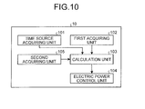
- FIG. 10 is a diagram illustrating an example of the functional configuration of the communication apparatus 10 according to a modification of the second embodiment.
- the communication apparatus 10 further includes a second acquiring unit 105.
- the second acquiring unit 105 includes a function of acquiring traffic information including predicted time for the own vehicle to arrive at the nearest traffic light 30 (the predicted time of arrival). In this example, the predicted time of arrival is calculated by taking the congestion on the road and the like into account.
- the second acquiring unit 105 can acquire the traffic information from the ITS or other external systems, for example.
- the timing at which the second acquiring unit 105 acquires the traffic information is optional, and the second acquiring unit 105 may acquire the traffic information in synchronization with the timing of receiving packets from the traffic light 30.
- the calculation unit 103 determines whether the own vehicle can pass through the nearest traffic light 30 by using one or more pieces of the traffic light information acquired by the first acquiring unit 102 and the traffic information acquired by the second acquiring unit 105. For example, the calculation unit 103 can also determine whether the own vehicle can pass through the nearest traffic light 30 by using the start time and the end time of the red signal included in the packets transmitted from the nearest traffic light 30, and the predicted time of arrive included in the traffic information. For example, if the predicted time of arrival is later than the start time of the red signal and earlier than the end time of the red signal, the calculation unit 103 may determine that the own vehicle cannot pass through the nearest traffic light 30.
- the method for determining whether the own vehicle can pass through the nearest traffic light 30 is not limited to the above-described method, and different methods can be employed.
- the calculation unit 103 instructs the ECU controlling the car navigation to determine whether the own vehicle can pass through the nearest traffic light 30 (from a different viewpoint, whether the own vehicle will stop at the nearest traffic light 30) and receives the result, although the operation is not limited thereto.
- the calculation unit 103 may receive the information required for the determination above from the ECU controlling the car navigation, for example, and make the determination based on the received information.
- the electric power control unit 104 controls the electric power state of the own vehicle that is running to be the minimum electric power state allowing the own vehicle to run to the nearest traffic light 30.
- FIG. 11 is a flowchart illustrating an example of the operations of the communication apparatus 10 according to the modification of the second embodiment. Details of the process at Step S301 illustrated in FIG. 11 are the same as those of the process at Step S201 illustrated in FIG. 9 .
- the second acquiring unit 105 acquires the above-described traffic information (Step S302) at the same time as Step S301 illustrated in FIG. 10 .
- the configuration is not limited thereto.
- the second acquiring unit 105 may request traffic information from an external system such as the ITS by using the reception of a packet at Step S301 as a trigger, and acquire the traffic information from the external system.
- Step S303 determines whether the own vehicle can pass through the nearest traffic light 30 by using the traffic information acquired at Step S302 and the packets transmitted from the nearest traffic light 30 identified at Step S303 (Step S304).
- the calculation unit 103 instructs the ECU controlling the car navigation to determine whether the own vehicle can pass through the nearest traffic light 30.
- the ECU that has received this instruction determines whether the own vehicle can pass through the nearest traffic light 30 by comparing the predicted time of arrive included in the traffic information with the start time and the end time of the red signal included in the packets transmitted from the nearest traffic light 30, and passes the determination result to the calculation unit 103.
- Step S304 If the ECU determines that the own vehicle can pass through the nearest traffic light 30 (Yes at Step S304), the process sequence ends. By contrast, if the ECU determines that the own vehicle cannot pass through the nearest traffic light 30 (No at Step S304), the process sequence proceeds to Step S305. Details of the process from Steps S305 to S315 illustrated in FIG. 11 are the same as those of the process from Steps S204 to S213 illustrated in FIG. 9 , and the detailed description thereof is omitted.
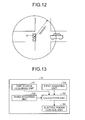
- the first acquiring unit 102 acquires only the traffic light information (the packets) transmitted from the traffic light 30 whose distance to the own vehicle is equal to or smaller than a reference value (a radius r in the example illustrated in FIG. 12 ). If the distance between the own vehicle and the traffic light 30 from which the received packets are transmitted exceeds the radius r, the first acquiring unit 102 discards the received packets.
- the value of the above-described radius r may be unique to the vehicle or determined based on the congestion on the road or the legal speed. If the value of the radius r is unique to the vehicle, it can be set by a car mechanic through the OBD port 20 illustrated in FIG. 1 at the factory shipment. If the value of the radius r is determined based on the congestion on the road, an inquiry about the congestion on the road can be referred to the server that controls the traffic information. If the value of the radius r is determined based on the legal speed, the radius r can be determined based on the geographic information (the above-described navigation information) stored in the ECU controlling the car navigation or the like. If the vehicle includes a camera system, for example, the speed sign can be image-processed and the legal speed can be recognized. Alternatively, an inquiry can be referred to the server that controls the traffic information to determine the legal speed.
- the first acquiring unit 102 determines whether the value of the distance between the own vehicle and the traffic light 30 from which the packets are transmitted is equal to or smaller than the radius r determined in advance. If the value of the distance between the own vehicle and the traffic light 30 from which the packets are transmitted exceeds the radius r, the first acquiring unit 102 discards the received packets. For example, the first acquiring unit 102 can instruct the ECU controlling the car navigation to determine whether the value of the distance between the own vehicle and the traffic light 30 from which the packets are transmitted is equal to or smaller than the radius r and receive the result.
- the first acquiring unit 102 can also receive the information required for the determination above from the ECU controlling the car navigation, and determine whether the value of the distance between the own vehicle and the traffic light 30 from which the packets are transmitted is equal to or smaller than the radius r based on the received information.
- the control unit 13 compares the information on the radius r stored in the storage unit 12 with the value of a distance d between the own vehicle and the traffic light 30 from which the packets are transmitted. If the value indicates d > r, the received packets are discarded.
- FIG. 13 is a diagram illustrating an example of the functional configuration of the communication apparatus 10 according to the fourth embodiment.
- the communication apparatus 10 further includes a third acquiring unit 106, which differs from the first embodiment.
- the third acquiring unit 106 acquires, from another vehicle, the vehicle position information indicating the position of the other vehicle and the stop determination information indicating whether the other vehicle is being stopped.
- the calculation unit 103 calculates the signal waiting time by using second predicted time of arrival indicating predicted time for the own vehicle to arrive at the second vehicle and the traffic light information acquired from the nearest traffic light 30.
- the flowchart illustrating an example of operations of the communication apparatus 10 according to the present embodiment is basically the same as the flowchart illustrated in FIG. 8 .
- the calculation unit 103 calculates a distance r6 from the present position of the own vehicle to the second vehicle by using the vehicle position information of the second vehicle acquired by the third acquiring unit 106. For example, the calculation unit 103 can calculate the distance r6 based on the vehicle position information acquired by the second vehicle and the above-described navigation information.
- the calculation unit 103 can therefore calculate the signal waiting time by using the second predicted time of arrival rather than the above-described predicted time of arrival (the calculation method is the same as that in the first embodiment). Other details are the same as those in the first embodiment.
- the present invention is not directly limited to the above embodiments.
- the present invention can be embodied by changing components without departing from the spirit and scope of the present invention when practiced.
- various aspects of the present invention can be made by properly combining the components of the above embodiments. For example, some components may be eliminated from all of the components of the above embodiments.
- the components of different embodiments and modifications may be properly combined with the described component.
- the electric power state during stop of the vehicle is controlled in a multistage manner in accordance with the signal waiting time.
- the configuration is not limited thereto.
- the electric power state during stop of the vehicle may be controlled in a multistage manner in a different way in accordance with the state of a factor to prevent the vehicle from running (e.g., the above-described waiting for signal).
- the computer program executed by the communication apparatus 10 or the ECUs in the vehicle may be provided in a manner recorded as an installable or executable file format on a computer-readable recording medium, such as a compact disc read-only memory (CD-ROM), a flexible disk (FD), a compact disc recordable (CD-R), a digital versatile disc (DVD), and a universal serial bus (USB).
- a computer-readable recording medium such as a compact disc read-only memory (CD-ROM), a flexible disk (FD), a compact disc recordable (CD-R), a digital versatile disc (DVD), and a universal serial bus (USB).
- CD-ROM compact disc read-only memory
- FD flexible disk
- CD-R compact disc recordable
- DVD digital versatile disc
- USB universal serial bus
- the computer program executed by the communication apparatus 10 or the ECUs in the vehicle may be provided or distributed over a network such as the Internet.
- various computer programs may also be provided in a manner embedded in advance in a nonvolatile recording medium, such
- An embodiment achieves appropriate energy saving operation in accordance with the signal waiting time.
Abstract
Description
- The present application claims priority to and incorporates by reference the entire contents of Japanese Patent Application No.
2014-162926 2015-123138 - The present invention relates to an information processing apparatus, an information processing method, and a computer program product.
- Some energy saving systems can be provided to a vehicle (including onboard equipment) stopping at the red signal. For example, Japanese Patent Application Laid-open No.
2012-3351 - However, in conventional technologies, no system has been provided that controls the electric power state of the vehicle in a multistage manner in accordance with a time period during which the vehicle stops at the traffic light (hereinafter also referred to as "signal waiting time").
- It is an object of the present invention to at least partially solve the problems in the conventional technology.
- An information processing apparatus is mounted on a vehicle. The information processing apparatus includes: a first acquiring unit that acquires, from each of one or more traffic lights, traffic light information including identifying information for identifying a corresponding traffic light, position information of the corresponding traffic light, and start time and end time of lighting in a color of a traffic signal indicating stop of the vehicle; a calculation unit that calculates a signal waiting time that indicates a time period for the vehicle to stop at a traffic light by using one or more pieces of the traffic light information; and an electric power control unit that controls an electric power state during stop of the vehicle in a multistage manner in accordance with the signal waiting time.
- An information processing method is executed by an information processing apparatus mounted on a vehicle. The information processing method includes: first acquiring, from each of one or more traffic lights, traffic light information including identifying information for identifying a corresponding traffic light, position information of the corresponding traffic light, and start time and end time of lighting in a color of a traffic signal indicating stop of the vehicle; calculating a signal waiting time that indicates a time period for the vehicle to stop at the traffic light by using one or more pieces of the traffic light information; and controlling an electric power state during stop of the vehicle in a multistage manner in accordance with the signal waiting time.
- A computer program product includes a non-transitory computer-readable medium containing an information processing program. The program causes a computer mounted on a vehicle to execute: first acquiring, from one or more traffic lights, traffic light information including identifying information for identifying the traffic lights, position information of the traffic lights, and start times and end times of lighting in a color of a traffic signal indicating stop of the vehicle; calculating a signal waiting time that indicates a time period for the vehicle to stop at the traffic light by using one or more pieces of the traffic light information; and controlling an electric power state during stop of the vehicle in a multistage manner in accordance with the signal waiting time.
- The above and other objects, features, advantages and technical and industrial significance of this invention will be better understood by reading the following detailed description of presently preferred embodiments of the invention, when considered in connection with the accompanying drawings.
-
-
FIG. 1 is a diagram illustrating an example of the configuration of an electronic control unit (ECU) in a vehicle; -
FIG. 2 is a diagram illustrating an example of the configuration of a communication apparatus; -
FIG. 3 is a diagram illustrating an example of the configuration of a traffic light; -
FIG. 4 is a diagram illustrating an example of the functional configuration of the communication apparatus; -
FIG. 5 is a diagram for explaining an example of a calculation method of a signal waiting time; -
FIGS. 6A and 6B are diagrams for explaining a changing method of a prescribed time period; -
FIG. 7 is a diagram for explaining that an electric power control unit selects the energy saving level during stop of the vehicle in accordance with the signal waiting time; -
FIG. 8 is a flowchart illustrating an example of operations of a communication apparatus according to a first embodiment of the present invention; -
FIG. 9 is a flowchart illustrating an example of operations of a communication apparatus according to a second embodiment of the present invention; -
FIG. 10 is a diagram illustrating an example of the functional configuration of a communication apparatus according to a modification of the second embodiment; -
FIG. 11 is a flowchart illustrating an example of operations of the communication apparatus according to the modification of the second embodiment; -
FIG. 12 is a diagram for explaining a method for acquiring packets according to a third embodiment of the present invention; -
FIG. 13 is a diagram illustrating an example of the functional configuration of a communication apparatus according to a fourth embodiment of the present invention; and -
FIG. 14 is a diagram for explaining a calculation method of second predicted time of arrival. - Hereinafter, an information processing apparatus, an information processing method, and a computer program product according to some embodiments of the present invention will be described in detail with reference to accompanying drawings. Hereinafter, "vehicle" refers to an object capable of running on a road, including cars and motorbikes. Examples of vehicles include a diesel vehicle, a fuel cell electric vehicle, a hybrid vehicle, and an electric vehicle.
-
FIG. 1 is a diagram illustrating an example of the configuration of an electronic control unit (ECU) in a vehicle according to a first embodiment of the present invention. The example illustrated inFIG. 1 includes a plurality of (three in the example illustrated inFIG. 1 ) domains (control systems), each including a plurality of ECUs (1, 2, and 3). Each of the domains integrally controls a plurality of ECUs belonging to the corresponding domain and is coupled to acommunication apparatus 10 externally communicating with a device and the like. The example illustrated inFIG. 1 includes three domains, out of which a first domain includes anECU 1, anECU 4, and anECU 5. TheECU 1 integrally controls theECU 4 and theECU 5 and is coupled to thecommunication apparatus 10. A second domain includes anECU 2, anECU 6, and anECU 7. TheECU 2 integrally controls theECU 6 and theECU 7 and is coupled to thecommunication apparatus 10. A third domain includes anECU 3, anECU 8, and anECU 9. TheECU 3 integrally controls theECU 8 and theECU 9 and is coupled to thecommunication apparatus 10. - While
FIG. 1 illustrates the three domains, the number and types of domains may be changed optionally. Examples of the domains include an infotainment system (a control system including an audio visual system, a car navigation, and an electronic toll collection (ETC) system, for example), a body system (a control system including meters, a vehicle air-conditioner, and windows, for example), a power train system (a control system including an engine and a transmission, for example), and a chassis system (a control system including a brake, a steering, and a collision avoidance mechanism, for example). - An on-board diagnostics system (OBD) notifies a driver of a fault point in the vehicle. Examples of OBD types include, but are not limited to, OBD-I and OBD-II, out of which OBD-II is adopted in this example. An
OBD port 20 illustrated inFIG. 1 is an interface for coupling the system (OBD) and thecommunication apparatus 10 to each other. The configuration of the ECU in the vehicle is not limited to the configuration illustrated inFIG. 1 , and other various ECU configurations may be adopted. The domains each may include a communication apparatus, for example. Alternatively, an ECU configuration in a vehicle may be included in an advanced driver assistance system (ADAS), for example. -
FIG. 2 is a diagram illustrating an example of the configuration of thecommunication apparatus 10. As illustrated inFIG. 2 , thecommunication apparatus 10 includes a communication unit 11, astorage unit 12, acontrol unit 13, a timer 14, and an input/output unit 15. The communication unit 11 communicates with an external device outside of the vehicle (e.g., a later-describedtraffic light 30, intelligent transport systems (ITS), or other external systems). Thestorage unit 12 stores various types of information such as information required for transmitting and receiving packets. Thecontrol unit 13 integrally controls entire operations of thecommunication apparatus 10 and is constituted by a CPU in this example. The timer 14 measures time. The input/output unit 15 exchanges information in the vehicle. The communication unit 11, thecontrol unit 13, and the timer 14 may be implemented with software or hardware. In hardware implementation, the CPU executing software processing during communication processing can execute other processing. If no processing is required, the CPU can shift to the energy saving mode. Thestorage unit 12 may be a USB memory, an SD memory, a RAM, and the like, as long as they can store packets therein. Thestorage unit 12 needs to include a reading function and a writing function. -
FIG. 3 is a diagram illustrating an example of the configuration of atraffic light 30 installed on a road. As illustrated inFIG. 3 , thetraffic light 30 includes a communication unit 31, astorage unit 32, acontrol unit 33, atimer 34, an input/output unit 35, and alighting unit 36. The communication unit 31 communicates with an external device out of the traffic light 30 (e.g., thecommunication apparatus 10 of the vehicle). Thestorage unit 32 stores therein various types of information such as information required for transmitting and receiving packets. Thecontrol unit 33 integrally controls entire operations of thetraffic light 30 and is constituted by a CPU in this example. Thetimer 34 measures time. The input/output unit 35 exchanges information in thetraffic light 30 and functions as a unit for coupling thecontrol unit 33 to thelighting unit 36, for example. Thelighting unit 36 lights up traffic signals such as a red signal indicating stop of the vehicle and the green signal permitting advance of the vehicle. The communication unit 31, thecontrol unit 33, and thetimer 34 may be implemented with software or hardware. In hardware implementation, the CPU executing software processing during communication processing can execute other processing. If no processing is required, the CPU can shift to the energy saving mode. Thestorage unit 32 may be a USB memory, an SD memory, a RAM, and the like, as long as they can store packets therein. Thestorage unit 32 needs to include a reading function and a writing function. - In the present embodiment, the
traffic light 30 periodically broadcasts packets including information of the traffic light 30 (traffic light information). The traffic light information includes at least an IP address, position information of thetraffic light 30, and start time and end time of lighting in a color of the traffic signal indicating stop of the vehicle (red in this example). The IP address may be global IPv4 or IPv6 and is used for identifying theindividual traffic light 30. The start time of lighting in the color of the traffic signal indicating stop of the vehicle may be hereinafter referred to as "start time of the red signal". The end time of lighting in the color of the traffic signal indicating stop of the vehicle may be hereinafter referred to as "end time of the red signal". In this example, the IP address can be considered to correspond to "identifying information" in claims herein, but is not limited thereto. If thetraffic light 30 indicates the red signal, the broadcast packets include the start time and the end time of the present red signal. If thetraffic light 30 indicates the green signal, the broadcast packets include the start time and the end time of the next red signal. Thecontrol unit 33 of thetraffic light 30 monitors thetimer 34 and generates packets to be broadcast at regular intervals (the value of the interval may be set in a register in the control unit 33). Thecontrol unit 33 then stores the generated packets in thestorage unit 32. Subsequently, thecontrol unit 33 passes a head address in a queue in a storage area in thestorage unit 32 as the minimum information to the communication unit 31. The communication unit 31 broadcasts the packets to the outside of thetraffic light 30. The configuration and operation for passing the head address in a queue are not necessarily limited to those described above. - The above-described "color indicating stop of the vehicle" typically refers to the color indicating stop of the straight running of the vehicle.
-
FIG. 4 is a diagram illustrating an example of the functional configuration of thecommunication apparatus 10. AlthoughFIG. 4 mainly illustrates the functions according to the embodiments of the present invention for convenience of description, thecommunication apparatus 10 may include other functions. As illustrated inFIG. 4 , thecommunication apparatus 10 includes a timesource acquiring unit 101, a first acquiringunit 102, acalculation unit 103, and an electricpower control unit 104. These functions and units are achieved with any one of the components illustrated inFIG. 2 operating by a command from the CPU of thecommunication apparatus 10. In this example, thecommunication apparatus 10 can be considered to correspond to an "information processing apparatus" in claims herein, but is not limited thereto. The whole configuration of the ECU of the vehicle (the whole configuration illustrated inFIG. 1 ) can also be considered to correspond to the "information processing apparatus" in claims herein. In short, any configuration is acceptable, as long as the information processing apparatus including at least the functions illustrated inFIG. 4 are mounted on a vehicle. - The time
source acquiring unit 101 acquires time source. The time source can be acquired from a global positioning system (GPS) satellite or a code division multiple access (CDMA) mobile-phone base station. Thetraffic light 30 also acquires time source in the same manner, thereby synchronizing time between thetraffic light 30 and the vehicle. - The first acquiring
unit 102 acquires, from one ormore traffic lights 30, traffic light information including IP addresses for identifying thetraffic lights 30, position information of thetraffic lights 30, and start times and end times of the red signal. In the present embodiment, the first acquiringunit 102 receives (acquires), from one ormore traffic lights 30, the above-described packets to be periodically broadcast. - The
calculation unit 103 calculates the signal waiting time that indicates a time period for the own vehicle to stop at thetraffic light 30 by using one or more pieces of the traffic light information acquired by the first acquiringunit 102. More specifically, thecalculation unit 103 calculates the signal waiting time by using predicted time of arrival and the traffic light information acquired from the nearest traffic light. The predicted time of arrival indicates predicted time for the own vehicle to arrive at the nearest traffic light. In addition, thecalculation unit 103 identifies thenearest traffic light 30 existing in the advance direction of the own vehicle based on navigation information indicating the position information of a plurality oftraffic lights 30 and the respective IP addresses, and the advance direction of the own vehicle. Thecalculation unit 103 then calculates the signal waiting time by using the traffic light information including the IP address of the identifiedtraffic light 30 out of the one or more pieces of the traffic light information acquired by the first acquiringunit 101. The navigation information typically indicates the position of the own vehicle on geographic information prepared in advance. In this example, the navigation information also includes the IP addresses of thetraffic lights 30 existing on the geographic information. - As illustrated in
FIG. 2 , the communication unit 11 of thecommunication apparatus 10 receives packets broadcast from thetraffic light 30 and stores them in thestorage unit 12. The communication unit 11 passes the head address in a queue in the storage area in thestorage unit 12 as the minimum information to thecontrol unit 13. Thecontrol unit 13 transfers the source IP address of the broadcast packets to the ECU controlling the car navigation. The configuration and operation for passing the head address in a queue are not necessarily limited thereto. - The ECU controlling the car navigation compares the IP address of the
traffic light 30 in the navigation information stored in advance in the ECU with the source IP address of the broadcast packets. The ECU controlling the car navigation thus can identify thetraffic light 30 from which the packets are transmitted. For example, thecontrol unit 13 may transfer the position information of thetraffic light 30 in the traffic light information included in the broadcast packets to the ECU controlling the car navigation. On this occasion, the ECU controlling the car navigation compares the position information of thetraffic light 30 in the navigation information stored in advance in the ECU with the position information transferred from thecontrol unit 13. The ECU controlling the car navigation thus can identify thetraffic light 30 corresponding to the position information transferred from thecontrol unit 13. Subsequently, the ECU controlling the car navigation identifies, under the instruction of thecontrol unit 13, thenearest traffic light 30 existing in the advance direction of the own vehicle out of the one ormore traffic lights 30 that each have broadcast packets. The ECU controlling the car navigation then uses the packets from the identified traffic light 30 (hereinafter also referred to as "targetedtraffic light 30") to calculate the above-described signal waiting time. While the ECU controlling the car navigation can identify (estimate) the advance direction of the own vehicle based on the route to the destination and the present position of the own vehicle, for example, the method for identifying the advance direction of the own vehicle is optional and not limited thereto. - As described above, the packets transmitted from the targeted
traffic light 30 include the IP address of the targetedtraffic light 30, the position information of the targetedtraffic light 30, the start time and the end time of the red signal. The ECU controlling the car navigation can calculate the signal waiting time by using these pieces of information. As illustrated inFIG. 5 , the distance from the present position of the own vehicle to the stop line of the targetedtraffic light 30 is determined as r5, the speed of the own vehicle is determined as v1, the start time of the red signal is determined as t1, the end time of the red signal is determined as t2, and the present time is determined as t3, for example. The distance r5 can be calculated by using the above-described navigation information, for example. The speed v1 may be detected by the ECU controlling the car navigation or acquired from another ECU. On this occasion, the predicted time for the own vehicle to arrive at the targeted traffic light 30 (hereinafter also referred to as "predicted time of arrival") is calculated as t3 + r5/v1 = t4. If the predicted time of arrival t4 is later than the start time t1 of the red signal and earlier than the end time t2 of the red signal (t1 < t4 < t2), the own vehicle can be determined to stop at the targetedtraffic light 30. The signal waiting time is calculated as t2 - t4. - If the predicted time of arrival t4 is earlier than the start time t1 of the red signal, the own vehicle is determined not to stop at (to pass through) the targeted
traffic light 30. However, even if the predicted time of arrival t4 is earlier than the start time t1 of the red signal, if the time difference between the predicted time of arrival t4 and the start time t1 of the red signal is equal to or smaller than a threshold, the own vehicle may be determined to stop at the targetedtraffic light 30. On this occasion, the signal waiting time is calculated as t2 - t4. The above-described threshold may be variably set depending on information indicating the congestion on the road, for example. If the own vehicle does not stop at the targetedtraffic light 30, no signal waiting time occurs; therefore, the signal waiting time is not calculated. - As described above, in the present embodiment, the ECU controlling the car navigation can determine whether the own vehicle stops at the
nearest traffic light 30 and also calculate the signal waiting time by using the traffic light information (e.g., an IP address) included in the packets transmitted from the targetedtraffic light 30 and the predicted time of arrival t4. The predicted time of arrival t4 may be calculated by the ECU controlling the car navigation, or may be calculated by another ECU, from which the ECU controlling the car navigation receives the calculation result. The calculation method of the predicted time of arrival t4 is optional and not limited to the above-described method. For example, the predicted time of arrival t4 may be calculated by taking into account the distance r3 from the vehicle (own vehicle) to the targetedtraffic light 30 illustrated inFIG. 5 . In addition, the predicted time of arrival t4 may be calculated by taking into account the information indicating the congestion on the road that can be acquired from the ITS or other external systems. The ECU controlling the car navigation notifies thecontrol unit 13 of the signal waiting time calculated as described above. - In this example, the control unit 13 (the calculation unit 103) instructs the ECU controlling the car navigation to calculate the signal waiting time and receives the result. This configuration and operation are also included in the concept that "the
calculation unit 103 calculates the signal waiting time that indicates a time period for the vehicle to stop at thetraffic light 30 by using one or more pieces of the traffic light information acquired by the first acquiringunit 102". In addition, the control unit 13 (the calculation unit 103) may receive the information required for calculating the signal waiting time (e.g., the above-described navigation information) from the ECU controlling the car navigation and calculate the signal waiting time based on the received information, for example. - Description will be continued with reference to
FIG. 4 again. The electricpower control unit 104 controls the electric power state of the own vehicle during stop of the own vehicle in a multistage manner in accordance with the signal waiting time calculated by thecalculation unit 103. More specifically, the electricpower control unit 104 performs control so that the power consumption during stop of the own vehicle decreases with an increase in the signal waiting time. For example, if the signal waiting time exceeds a first threshold and is equal to or smaller than a second threshold that is larger than the first threshold, the electricpower control unit 104 controls the idling speed of the engine to the speed lower than the idling speed of when the signal waiting time equal to or smaller than the first threshold. If the signal waiting time exceeds the second threshold, the electricpower control unit 104 can control the engine to stop. In addition, for example, the electricpower control unit 104 can perform control so that the amount of light of an illumination device provided to the own vehicle (typically a headlight) decreases with an increase in the signal waiting time. - Here, the electric power state during stop of the own vehicle is the energy saving state (hereinafter also referred to as "energy saving mode") with smaller power consumption than the normal state (hereinafter also referred to as "normal mode") indicating the electric power state while the own vehicle is running. If no other vehicle exists between the nearest traffic light 30 (the targeted traffic light 30) and the own vehicle during stop of the own vehicle, the electric
power control unit 104 performs control so as to cancel the energy saving state a prescribed time period before the end of the signal waiting time. The prescribed time period preferably indicates a time period required for the own vehicle to return from the energy saving state to the normal state. - In the present embodiment, if any other vehicle exists between the
nearest traffic light 30 and the own vehicle during stop of the own vehicle, the electricpower control unit 104 changes the prescribed time period depending on the number of other vehicles. More specifically, if any other vehicle exists between thenearest traffic light 30 and the own vehicle during stop of the own vehicle, the electricpower control unit 104 changes the prescribed time period so that the time period decreases with an increase in the number of other vehicles. For example, inFIG. 6A , during stop of the own vehicle, the number of other vehicles existing between thenearest traffic light 30 and the own vehicle is "2". InFIG. 6B , during stop of the own vehicle, the number of other vehicles existing between thenearest traffic light 30 and the own vehicle is "1". On this occasion, the prescribed time period inFIG. 6A is set to a value smaller than that of the prescribed time period inFIG. 6B . Furthermore, the electricpower control unit 104 may perform control so as to cancel the energy saving state a prescribed time period after the end of the signal waiting time depending on the number of other vehicles existing between thenearest traffic light 30 and the own vehicle. Increased number of other vehicles existing between thenearest traffic light 30 and the own vehicle delays the start of running the own vehicle. Taking this into account, the control to cancel the energy saving state is delayed, thereby acquiring more advantageous effects of energy saving. - The method for determining whether any other vehicle exists between the
nearest traffic light 30 and the own vehicle is optional. For example, thecommunication apparatus 10 acquires, from another vehicle, vehicle position information indicating the position of the other vehicle (acquires in a certain cycle, for example). Based on the acquired vehicle position information and the above-described navigation information, thecommunication apparatus 10 can determine whether any other vehicle exists between thenearest traffic light 30 and the own vehicle. If any other vehicle exists between thenearest traffic light 30 and the own vehicle, thecommunication apparatus 10 can detect the number of other vehicles. -
FIG. 7 is a diagram for explaining that the electricpower control unit 104 selects the energy saving level during stop of the own vehicle in accordance with the signal waiting time calculated by thecalculation unit 103. The ordinate axis on the left side inFIG. 7 represents the signal waiting time (in the example illustrated inFIG. 7 , ranging from 0 to 10 minutes). The ordinate axis on the right side inFIG. 7 represents the energy saving level depending on the signal waiting time. While the correspondence information (the correspondence table) indicating the corresponding relation between the signal waiting time and the energy saving level is stored in thestorage unit 12 illustrated inFIG. 2 , for example, the destination of the correspondence information is optional and the information may be stored in an external device, for example. The correspondence information may be set by a car mechanic through theOBD port 20 at the factory shipment or during replacement of devices, for example. Alternatively, the correspondence information is displayed on a display (on the screen of the car navigation, the screen provided on the windshield, or the screen of a terminal installed on the own vehicle), for example. The correspondence information can be variably set through an input operation by a driver to the displayed correspondence information. On this occasion, a command corresponding to the user operation is interpreted by an ECU controlling the display. A control command corresponding to the interpretation result is transferred to an ECU controlling the correspondence information. Subsequently, the ECU controlling the correspondence information rewrites the correspondence information in accordance with the received control command. - In the example illustrated in
FIG. 7 , the energy saving level "1" is adopted if the signal waiting time ranges from 0 minutes to 1 minute. The level setting may be defined depending on the model of the vehicle or depending on the owner of the vehicle. For example, theenergy saving level 1 may be set so as not to shift to the energy saving mode because the signal waiting time is short. For another example, theenergy saving level 2 may shift to the energy saving mode in which the idling speed of the engine is controlled so as to be lower than the idling speed in the energy saving level 1 (in this example, the idling speed at the time of normal stop). In addition, the power consumption of ECUs each belonging to the corresponding domain may be variably controlled depending on the energy saving level, for example. For example, theenergy saving level 2 may shift to the energy saving mode in which the power consumption of only the ECU4 corresponding to the first domain illustrated inFIG. 1 and belonging to the first domain is controlled so as to be smaller than the power consumption in the normal operation (this may be combined with the above-described energy saving mode in which the idling speed of the engine is controlled so as to be lower than the idling speed in the energy saving level 1). For example, theenergy saving level 3 may shift to the energy saving mode in which the power consumption of all the ECUs (1, 4, and 5) corresponding to the first domain illustrated inFIG. 1 and belonging to the first domain is controlled so as to be smaller than the power consumption in the normal operation. The power consumption of any components of the ECU may be changed optionally. For example, the power consumption of the CPU alone may be changed. - As illustrated in
FIG. 2 , thecontrol unit 13 measures the signal waiting time and then compares it with the correspondence information stored in the storage unit 12 (refer toFIG. 7 ), thereby determining the energy saving level. When the own vehicle stops at thetraffic light 30, thecontrol unit 13 transfers the information to at least one of theECU 1, theECU 2, and theECU 3 illustrated inFIG. 1 in accordance with the determined energy saving level. The ECU that has received the information changes the setting of the register in the ECU itself to the setting corresponding to the determined energy saving level. The stop of the own vehicle at thetraffic light 30 can be detected with different methods. Suppose the second domain illustrated inFIG. 1 serves as a power train system. TheECU 6 monitors the number of revolutions of the driving wheel. If the number of revolutions becomes zero, theECU 6 notifies thecontrol unit 13 in thecommunication apparatus 10 through theECU 2 to that effect. This notification triggers thecontrol unit 13 to recognize stop of the own vehicle. -
FIG. 8 is a flowchart illustrating an example of operations of thecommunication apparatus 10 according to the present embodiment. As illustrated inFIG. 8 , the first acquiringunit 102 first acquires packets from one or more traffic lights 30 (Step S101). Thecalculation unit 103 then identifies the packets transmitted from thenearest traffic light 30 existing in the advance direction of the own vehicle out of the one or more groups of packets acquired at Step S101 (Step S102). The identifying method has been described above. In the present embodiment, thecalculation unit 103 instructs the ECU controlling the car navigation to identify the packets transmitted from thenearest traffic light 30 and receives the result. Subsequently, thecalculation unit 103 determines whether the own vehicle will stop at the nearest traffic light 30 (Step S103). As described above, thecalculation unit 103 can also compare the start time and the end time of the red signal included in the packets transmitted from thenearest traffic light 30 with the predicted time for the own vehicle to arrive at the nearest traffic light 30 (the predicted time of arrival), thereby determining whether the own vehicle will stop at thenearest traffic light 30. In the present embodiment, thecalculation unit 103 instructs the ECU controlling the car navigation to determine whether the own vehicle stops at thenearest traffic light 30 and receives the result. - If the
calculation unit 103 determines that the own vehicle will not stop at the nearest traffic light 30 (No at Step S103), the process sequence ends. By contrast, if thecalculation unit 103 determines that the own vehicle will stop at the nearest traffic light 30 (Yes at Step S103), thecalculation unit 103 calculates the signal waiting time by using the packets transmitted from the nearest traffic light 30 (Step S104). In the present embodiment, thecalculation unit 103 instructs the ECU controlling the car navigation to calculate the signal waiting time and receives the result. The calculation method of the signal waiting time has been described above. For example, thecalculation unit 103 can calculate the signal waiting time by using the start time and the end time of the red signal included in the packets transmitted from thenearest traffic light 30, and the predicted time of arrival. Subsequently, the electricpower control unit 104 determines the energy saving level during stop of the own vehicle in accordance with the signal waiting time calculated at Step S104 (Step S105). The determining method of the energy saving level has been described above. - If the own vehicle stops (Yes at Step S106), the electric
power control unit 104 performs control to shift to the energy saving mode corresponding to the energy saving level determined at Step S105 (Step S107). The electricpower control unit 104 then determines whether any other vehicle exists between thenearest traffic light 30 and the own vehicle (Step S108). If the result at Step S108 is positive (Yes at Step S108), the electricpower control unit 104 changes a prescribed time period T depending on the number of other vehicles existing between thenearest traffic light 30 and the own vehicle (Step S109). The electricpower control unit 104 determines whether it is T second(s) before the end of the signal waiting time (Step S110). By contrast, if the result at Step S108 is negative (No at Step S108), the electricpower control unit 104 does not change the prescribed time period T and determines whether it is T second(s) before the end of the signal waiting time (Step S110). - If it is T second(s) before the end of the signal waiting time (Yes at Step S110), the electric
power control unit 104 performs control to cancel the energy saving mode (Step S111). As a result, the own vehicle starts running at the timing at which thetraffic light 30 changes its light of color to green. - As described above, in the present embodiment, the electric power state during stop of the vehicle is controlled in a multistage manner in accordance with the signal waiting time. The present embodiment therefore can provide advantageous effects that more appropriate energy saving operation can be achieved. The configuration according to the present embodiment is effective in particular for vehicles, such as electric vehicles, that require extremely high energy-saving operation for increased travelable distance.
- In the above-described first embodiment, the electric
power control unit 104 changes the prescribed time period depending on the number of other vehicles if any other vehicle exists between thenearest traffic light 30 and the own vehicle during stop of the own vehicle. The embodiment is, however, not limited to this. For example, the electricpower control unit 104 can also performs control to cancel the energy saving state according to the timing at which, out of other vehicles existing between thenearest traffic light 30 and the own vehicle, another vehicle nearest to the own vehicle (a third vehicle) starts running. For example, thecommunication apparatus 10 includes a function (a later-described third acquiring unit 106) of acquiring, from the other vehicle, the vehicle position information indicating the position of the other vehicle and stop determination information indicating whether the other vehicle is being stopped. If the stop determination information indicating that the third vehicle is not being stopped (that is, the third vehicle has started running) is acquired from the third vehicle, the electricpower control unit 104 may perform control to cancel the energy saving state. - A second embodiment will now be described. Overlapped explanation with the description in the first embodiment will be omitted as appropriate. The configuration of the ECUs in the vehicle in the present embodiment is the same as that in the first embodiment. However, in the present embodiment, the electric
power control unit 104 further includes a function of controlling the electric power state of the own vehicle during running in accordance with the distance that the own vehicle will travel before the own vehicle stops at thetraffic light 30. In the present embodiment, if the own vehicle is determined to stop at thenearest traffic light 30, thecalculation unit 103 calculates the distance from the present position of the own vehicle to the stop line of thenearest traffic light 30 as the distance that the own vehicle will travel before the own vehicle stops at thetraffic light 30. In this example, thecalculation unit 103 instructs the ECU controlling the car navigation to calculate the distance from the present position of the own vehicle to the stop line of thenearest traffic light 30 and receives the result, although the operation is not limited thereto. Thecalculation unit 103 may receive the information required for calculating the distance (e.g., the above-described navigation information) from the ECU controlling the car navigation, for example, and calculate the distance based on the received information. -
FIG. 9 is a flowchart illustrating an example of operations of thecommunication apparatus 10 according to the present embodiment. Details of the process from Steps S201 to S205 illustrated inFIG. 9 are the same as those of the process from Steps S101 to S105 illustrated inFIG. 8 , and the detailed description thereof is omitted. After Step S205, thecalculation unit 103 calculates the distance from the present position of the own vehicle to the stop line of the nearest traffic light 30 (Step S206). As described above, in this example, thecalculation unit 103 instructs the ECU controlling the car navigation to calculate the distance from the present position of the own vehicle to the stop line of thenearest traffic light 30. The ECU that has received this instruction calculates the distance from the present position of the own vehicle to the stop line of thenearest traffic light 30 with reference to the navigation information stored in the ECU, for example, and passes the calculation result to thecalculation unit 103. Subsequently, the electricpower control unit 104 controls the electric power state of the own vehicle that is running in accordance with the distance calculated at Step S206 (Step S207). In this example, the electricpower control unit 104 controls the electric power state of the own vehicle that is running to the minimum electric power state allowing the own vehicle to run to thenearest traffic light 30. For example, if the distance calculated at Step S206 is equal to or smaller than the threshold, the electricpower control unit 104 can perform control to stop the engine of the own vehicle and let the vehicle run inertially. - Details of the process from Steps S208 to S213 illustrated in
FIG. 9 are the same as those of the process from Steps S106 to S109 illustrated inFIG. 8 , and the detailed description thereof is omitted. -
FIG. 10 is a diagram illustrating an example of the functional configuration of thecommunication apparatus 10 according to a modification of the second embodiment. As illustrated inFIG. 10 , thecommunication apparatus 10 further includes a second acquiringunit 105. The second acquiringunit 105 includes a function of acquiring traffic information including predicted time for the own vehicle to arrive at the nearest traffic light 30 (the predicted time of arrival). In this example, the predicted time of arrival is calculated by taking the congestion on the road and the like into account. The second acquiringunit 105 can acquire the traffic information from the ITS or other external systems, for example. The timing at which the second acquiringunit 105 acquires the traffic information is optional, and the second acquiringunit 105 may acquire the traffic information in synchronization with the timing of receiving packets from thetraffic light 30. - In this example, the
calculation unit 103 determines whether the own vehicle can pass through thenearest traffic light 30 by using one or more pieces of the traffic light information acquired by the first acquiringunit 102 and the traffic information acquired by the second acquiringunit 105. For example, thecalculation unit 103 can also determine whether the own vehicle can pass through thenearest traffic light 30 by using the start time and the end time of the red signal included in the packets transmitted from thenearest traffic light 30, and the predicted time of arrive included in the traffic information. For example, if the predicted time of arrival is later than the start time of the red signal and earlier than the end time of the red signal, thecalculation unit 103 may determine that the own vehicle cannot pass through thenearest traffic light 30. The method for determining whether the own vehicle can pass through thenearest traffic light 30 is not limited to the above-described method, and different methods can be employed. In this example, thecalculation unit 103 instructs the ECU controlling the car navigation to determine whether the own vehicle can pass through the nearest traffic light 30 (from a different viewpoint, whether the own vehicle will stop at the nearest traffic light 30) and receives the result, although the operation is not limited thereto. For example, thecalculation unit 103 may receive the information required for the determination above from the ECU controlling the car navigation, for example, and make the determination based on the received information. - In the present embodiment, if the own vehicle cannot pass through the
nearest traffic light 30, the electricpower control unit 104 controls the electric power state of the own vehicle that is running to be the minimum electric power state allowing the own vehicle to run to thenearest traffic light 30. -
FIG. 11 is a flowchart illustrating an example of the operations of thecommunication apparatus 10 according to the modification of the second embodiment. Details of the process at Step S301 illustrated inFIG. 11 are the same as those of the process at Step S201 illustrated inFIG. 9 . In this example, the second acquiringunit 105 acquires the above-described traffic information (Step S302) at the same time as Step S301 illustrated inFIG. 10 . However, the configuration is not limited thereto. For example, the second acquiringunit 105 may request traffic information from an external system such as the ITS by using the reception of a packet at Step S301 as a trigger, and acquire the traffic information from the external system. - Details of the process at Step S303 is the same as those of the process at Step S202 illustrated in
FIG. 9 . After Step S303, thecalculation unit 103 determines whether the own vehicle can pass through thenearest traffic light 30 by using the traffic information acquired at Step S302 and the packets transmitted from thenearest traffic light 30 identified at Step S303 (Step S304). As described above, in this example, thecalculation unit 103 instructs the ECU controlling the car navigation to determine whether the own vehicle can pass through thenearest traffic light 30. The ECU that has received this instruction determines whether the own vehicle can pass through thenearest traffic light 30 by comparing the predicted time of arrive included in the traffic information with the start time and the end time of the red signal included in the packets transmitted from thenearest traffic light 30, and passes the determination result to thecalculation unit 103. If the ECU determines that the own vehicle can pass through the nearest traffic light 30 (Yes at Step S304), the process sequence ends. By contrast, if the ECU determines that the own vehicle cannot pass through the nearest traffic light 30 (No at Step S304), the process sequence proceeds to Step S305. Details of the process from Steps S305 to S315 illustrated inFIG. 11 are the same as those of the process from Steps S204 to S213 illustrated inFIG. 9 , and the detailed description thereof is omitted. - A third embodiment will now be described. Overlapped explanation with the description in the first embodiment will be omitted as appropriate. The configuration of the ECUs in the own vehicle in the present embodiment is the same as that in the first embodiment. However, in the present embodiment, as illustrated in
FIG. 12 , the first acquiringunit 102 acquires only the traffic light information (the packets) transmitted from thetraffic light 30 whose distance to the own vehicle is equal to or smaller than a reference value (a radius r in the example illustrated inFIG. 12 ). If the distance between the own vehicle and thetraffic light 30 from which the received packets are transmitted exceeds the radius r, the first acquiringunit 102 discards the received packets. - The value of the above-described radius r may be unique to the vehicle or determined based on the congestion on the road or the legal speed. If the value of the radius r is unique to the vehicle, it can be set by a car mechanic through the
OBD port 20 illustrated inFIG. 1 at the factory shipment. If the value of the radius r is determined based on the congestion on the road, an inquiry about the congestion on the road can be referred to the server that controls the traffic information. If the value of the radius r is determined based on the legal speed, the radius r can be determined based on the geographic information (the above-described navigation information) stored in the ECU controlling the car navigation or the like. If the vehicle includes a camera system, for example, the speed sign can be image-processed and the legal speed can be recognized. Alternatively, an inquiry can be referred to the server that controls the traffic information to determine the legal speed. - In the present embodiment, if the first acquiring
unit 102 receives the packets from thetraffic light 30, the first acquiringunit 102 determines whether the value of the distance between the own vehicle and thetraffic light 30 from which the packets are transmitted is equal to or smaller than the radius r determined in advance. If the value of the distance between the own vehicle and thetraffic light 30 from which the packets are transmitted exceeds the radius r, the first acquiringunit 102 discards the received packets. For example, the first acquiringunit 102 can instruct the ECU controlling the car navigation to determine whether the value of the distance between the own vehicle and thetraffic light 30 from which the packets are transmitted is equal to or smaller than the radius r and receive the result. For example, the first acquiringunit 102 can also receive the information required for the determination above from the ECU controlling the car navigation, and determine whether the value of the distance between the own vehicle and thetraffic light 30 from which the packets are transmitted is equal to or smaller than the radius r based on the received information. - As illustrated in
FIG. 2 , after the communication unit 11 receives packets broadcast from thetraffic light 30, thecontrol unit 13 compares the information on the radius r stored in thestorage unit 12 with the value of a distance d between the own vehicle and thetraffic light 30 from which the packets are transmitted. If the value indicates d > r, the received packets are discarded. - A fourth embodiment will now be described. Overlapped explanation with the description in the first embodiment will be omitted as appropriate.
FIG. 13 is a diagram illustrating an example of the functional configuration of thecommunication apparatus 10 according to the fourth embodiment. As illustrated inFIG. 13 , thecommunication apparatus 10 further includes a third acquiringunit 106, which differs from the first embodiment. The third acquiringunit 106 acquires, from another vehicle, the vehicle position information indicating the position of the other vehicle and the stop determination information indicating whether the other vehicle is being stopped. - If the third acquiring
unit 106 acquires the stop determination information indicating that the other vehicle (referred to as "second vehicle") nearest to the own vehicle is being stopped from the second vehicle out of one or more other vehicles existing in the advance direction of the vehicle (own vehicle), thecalculation unit 103 calculates the signal waiting time by using second predicted time of arrival indicating predicted time for the own vehicle to arrive at the second vehicle and the traffic light information acquired from thenearest traffic light 30. The flowchart illustrating an example of operations of thecommunication apparatus 10 according to the present embodiment is basically the same as the flowchart illustrated inFIG. 8 . - For example, as illustrated in
FIG. 14 , suppose the own vehicle (the third acquiring unit 106) acquires the stop determination information indicating that the second vehicle is being stopped from the second vehicle being stopped at thenearest traffic light 30. On this occasion, thecalculation unit 103 calculates a distance r6 from the present position of the own vehicle to the second vehicle by using the vehicle position information of the second vehicle acquired by the third acquiringunit 106. For example, thecalculation unit 103 can calculate the distance r6 based on the vehicle position information acquired by the second vehicle and the above-described navigation information. Subsequently, thecalculation unit 103 divides the distance r6 by the speed v1 of the own vehicle (r6/v1) and adds the present time t3 thereto, thereby calculating the second predicted time of arrival (= t3 + r6/v1). Thecalculation unit 103 can therefore calculate the signal waiting time by using the second predicted time of arrival rather than the above-described predicted time of arrival (the calculation method is the same as that in the first embodiment). Other details are the same as those in the first embodiment. - The present invention is not directly limited to the above embodiments. The present invention can be embodied by changing components without departing from the spirit and scope of the present invention when practiced. In addition, various aspects of the present invention can be made by properly combining the components of the above embodiments. For example, some components may be eliminated from all of the components of the above embodiments. Furthermore, the components of different embodiments and modifications may be properly combined with the described component.
- In the above-described embodiments, the electric power state during stop of the vehicle is controlled in a multistage manner in accordance with the signal waiting time. However, the configuration is not limited thereto. The electric power state during stop of the vehicle may be controlled in a multistage manner in a different way in accordance with the state of a factor to prevent the vehicle from running (e.g., the above-described waiting for signal).
- The computer program executed by the
communication apparatus 10 or the ECUs in the vehicle may be provided in a manner recorded as an installable or executable file format on a computer-readable recording medium, such as a compact disc read-only memory (CD-ROM), a flexible disk (FD), a compact disc recordable (CD-R), a digital versatile disc (DVD), and a universal serial bus (USB). Alternatively, the computer program executed by thecommunication apparatus 10 or the ECUs in the vehicle may be provided or distributed over a network such as the Internet. Furthermore, various computer programs may also be provided in a manner embedded in advance in a nonvolatile recording medium, such as a read only memory (ROM). - An embodiment achieves appropriate energy saving operation in accordance with the signal waiting time.
- Although the invention has been described with respect to specific embodiments for a complete and clear disclosure, the appended claims are not to be thus limited but are to be construed as embodying all modifications and alternative constructions that may occur to one skilled in the art that fairly fall within the basic teaching herein set forth.
Claims (17)
- An information processing apparatus mounted on a vehicle, the information processing apparatus comprising:a first acquiring unit that acquires, from each of one or more traffic lights, traffic light information including identifying information for identifying a corresponding traffic light, position information of the corresponding traffic light, and start time and end time of lighting in a color of a traffic signal indicating stop of the vehicle;a calculation unit that calculates a signal waiting time that indicates a time period for the vehicle to stop at a traffic light by using one or more pieces of the traffic light information; andan electric power control unit that controls an electric power state during stop of the vehicle in a multistage manner in accordance with the signal waiting time.
- The information processing apparatus according to claim 1, wherein the electric power control unit performs control such that power consumption during stop of the vehicle decreases with an increase in the signal waiting time.
- The information processing apparatus according to claim 2, wherein if the signal waiting time exceeds a first threshold and is equal to or smaller than a second threshold that is larger than the first threshold, the electric power control unit controls an idling speed of an engine to a speed lower than an idling speed of when the signal waiting time equal to or smaller than the first threshold, and if the signal waiting time exceeds the second threshold, the electric power control unit controls the engine to stop.
- The information processing apparatus according to claim 2 or 3, wherein the electric power control unit performs control such that an amount of light of an illumination device provided to the vehicle decreases with an increase in the signal waiting time.
- The information processing apparatus according to any one of claims 1 to 4, wherein the electric power control unit controls an electric power state of the vehicle during running in accordance with a distance that the vehicle will travel before the vehicle stops at the traffic light.
- The information processing apparatus according to any one of claims 1 to 5, wherein the calculation unit calculates the signal waiting time by using predicted time of arrival indicating predicted time for the vehicle to arrive at a nearest traffic light and the traffic light information acquired from the nearest traffic light.
- The information processing apparatus according to any one of claims 1 to 6, further comprising a second acquiring unit that acquires traffic information including predicted time of arrival indicating predicted time for the vehicle to arrive at a nearest traffic light, wherein
the calculation unit determines whether the vehicle is capable of passing through the nearest traffic light by using one or more pieces of the traffic light information acquired by the first acquiring unit and the traffic information acquired by the second acquiring unit, and
if the vehicle is not capable of passing through the nearest traffic light, the electric power control unit controls an electric power state of the vehicle during running so as to be a minimum electric power state allowing the vehicle to run to the nearest traffic light. - The information processing apparatus according to any one of claims 1 to 7, wherein the calculation unit identifies a nearest traffic light existing in an advance direction of the vehicle based on navigation information indicating the position information and the identifying information on each of the traffic lights, and the advance direction of the vehicle, and calculates the signal waiting time by using the traffic light information including the identifying information on the identified traffic light out of one or more pieces of the traffic light information acquired by the first acquiring unit.
- The information processing apparatus according to any one of claims 1 to 8, wherein the first acquiring unit acquires only the traffic light information transmitted from the traffic light whose distance to the vehicle is equal to or smaller than a reference value.
- The information processing apparatus according to any one of claims 1 to 9, further comprising a third acquiring unit that acquires, from another vehicle, vehicle position information indicating a position of the other vehicle, and stop determination information indicating whether the other vehicle is being stopped, wherein
if the third acquiring unit acquires the stop determination information indicating that a second vehicle is being stopped from the second vehicle, the second vehicle being nearest to the vehicle out of one or more other vehicles existing in an advance direction of the vehicle, the calculation unit calculates the signal waiting time by using second predicted time of arrival indicating predicted time for the vehicle to arrive at the second vehicle and the traffic light information acquired from a nearest traffic light. - The information processing apparatus according to any one of claims 1 to 10, wherein
the electric power state during stop of the vehicle is an energy saving state with smaller power consumption than a normal state indicating an electric power state while the vehicle is running, and
if no vehicle exists between the nearest traffic light and the vehicle during stop of the vehicle, the electric power control unit performs control so as to cancel the energy saving state a prescribed time period before end of the signal waiting time. - The information processing apparatus according to claim 11, wherein the prescribed time period indicates a time period required for the vehicle to return from the energy saving state to the normal state.
- The information processing apparatus according to claim 11 or 12, wherein if any other vehicle exists between the nearest traffic light and the vehicle during stop of the vehicle, the electric power control unit changes the prescribed time period depending on number of other vehicles.
- The information processing apparatus according to claim 13, wherein if any other vehicle exists between the nearest traffic light and the vehicle during stop of the vehicle, the electric power control unit changes the prescribed time period such that the prescribed time period decreases with an increase in the number of the other vehicles.
- The information processing apparatus according to claim 11 or 12, wherein if any other vehicle exists between the nearest traffic light and the vehicle during stop of the vehicle, the electric power control unit performs control to cancel the energy saving state according to a timing at which a third vehicle starts running, the third vehicle being nearest to the vehicle out of the other vehicles existing between the nearest traffic light and the vehicle.
- An information processing method executed by an information processing apparatus mounted on a vehicle, the information processing method comprising:first acquiring, from each of one or more traffic lights, traffic light information including identifying information for identifying a corresponding traffic light, position information of the corresponding traffic light, and start time and end time of lighting in a color of a traffic signal indicating stop of the vehicle;calculating a signal waiting time that indicates a time period for the vehicle to stop at the traffic light by using one or more pieces of the traffic light information; andcontrolling an electric power state during stop of the vehicle in a multistage manner in accordance with the signal waiting time.
- A computer program product comprising a non-transitory computer-readable medium containing an information processing program, the program causing a computer mounted on a vehicle to execute:first acquiring, from one or more traffic lights, traffic light information including identifying information for identifying the traffic lights, position information of the traffic lights, and start times and end times of lighting in a color of a traffic signal indicating stop of the vehicle;calculating a signal waiting time that indicates a time period for the vehicle to stop at the traffic light by using one or more pieces of the traffic light information; andcontrolling an electric power state during stop of the vehicle in a multistage manner in accordance with the signal waiting time.
Applications Claiming Priority (2)
| Application Number | Priority Date | Filing Date | Title |
|---|---|---|---|
| JP2014162926 | 2014-08-08 | ||
| JP2015123138A JP2016037283A (en) | 2014-08-08 | 2015-06-18 | Information processing device, information processing method and program |
Publications (3)
| Publication Number | Publication Date |
|---|---|
| EP2985200A2 true EP2985200A2 (en) | 2016-02-17 |
| EP2985200A3 EP2985200A3 (en) | 2016-07-13 |
| EP2985200B1 EP2985200B1 (en) | 2018-11-14 |
Family
ID=54011987
Family Applications (1)
| Application Number | Title | Priority Date | Filing Date |
|---|---|---|---|
| EP15179957.4A Active EP2985200B1 (en) | 2014-08-08 | 2015-08-06 | Traffic lights information processing apparatus, information processing method, and computer program for controlling the electrical power consumption in the vehicle |
Country Status (3)
| Country | Link |
|---|---|
| US (2) | US9623873B2 (en) |
| EP (1) | EP2985200B1 (en) |
| JP (1) | JP2016037283A (en) |
Cited By (2)
| Publication number | Priority date | Publication date | Assignee | Title |
|---|---|---|---|---|
| FR3048457A1 (en) * | 2016-03-03 | 2017-09-08 | Peugeot Citroen Automobiles Sa | METHOD AND DEVICE FOR INHIBITING A STOP FUNCTION AND AUTOMATIC RESTART OF A THERMAL MOTOR OF A VEHICLE |
| CN107476918A (en) * | 2016-12-23 | 2017-12-15 | 宝沃汽车(中国)有限公司 | Start and stop method, system and the vehicle of engine |
Families Citing this family (11)
| Publication number | Priority date | Publication date | Assignee | Title |
|---|---|---|---|---|
| EP3118831B1 (en) * | 2014-03-10 | 2019-05-22 | Nissan Motor Co., Ltd | Traffic light detection device and traffic light detection method |
| JP6183251B2 (en) * | 2014-03-14 | 2017-08-23 | 株式会社デンソー | Electronic control unit |
| JP2016037283A (en) * | 2014-08-08 | 2016-03-22 | 株式会社リコー | Information processing device, information processing method and program |
| US9706354B2 (en) * | 2015-11-04 | 2017-07-11 | Visa International Service Association | In-vehicle access application |
| US10220850B2 (en) * | 2017-01-30 | 2019-03-05 | GM Global Technology Operations LLC | Vehicle propulsion systems and methods |
| JP6962127B2 (en) * | 2017-10-19 | 2021-11-05 | トヨタ自動車株式会社 | Traffic light information provision system, traffic light information provision method, and server used for it |
| CN107889076A (en) * | 2017-10-26 | 2018-04-06 | 深圳市元征软件开发有限公司 | Vehicular diagnostic method and vehicle diagnostic device |
| US10957190B2 (en) * | 2018-06-28 | 2021-03-23 | Intel Corporation | Traffic management system, components of a distributed traffic management system, prioritization/load-distribution system, and methods thereof |
| US20210284195A1 (en) * | 2020-03-13 | 2021-09-16 | Baidu Usa Llc | Obstacle prediction system for autonomous driving vehicles |
| CN115171415A (en) * | 2020-07-31 | 2022-10-11 | 北京航迹科技有限公司 | Method, apparatus, device and medium for determining parking position of vehicle |
| US20230339464A1 (en) * | 2022-04-20 | 2023-10-26 | GM Global Technology Operations LLC | Full speed range adaptive cruise control system for determining an adaptive launch time for a vehicle |
Citations (1)
| Publication number | Priority date | Publication date | Assignee | Title |
|---|---|---|---|---|
| JP2012003351A (en) | 2010-06-14 | 2012-01-05 | Sanyo Electric Co Ltd | Terminal device |
Family Cites Families (20)
| Publication number | Priority date | Publication date | Assignee | Title |
|---|---|---|---|---|
| JP4097009B2 (en) | 2001-11-28 | 2008-06-04 | 株式会社リコー | Electrophotographic photoreceptor test equipment |
| JP2004239127A (en) | 2003-02-05 | 2004-08-26 | Nissan Motor Co Ltd | Drive control device for hybrid vehicle |
| JP4866359B2 (en) * | 2005-09-07 | 2012-02-01 | パイオニア株式会社 | Recording / reproducing apparatus, recording / reproducing method, recording / reproducing program, and computer-readable recording medium |
| JP2007225072A (en) * | 2006-02-27 | 2007-09-06 | Hitachi Ltd | Control device for automobile |
| US8729446B2 (en) * | 2007-06-29 | 2014-05-20 | Orion Energy Systems, Inc. | Outdoor lighting fixtures for controlling traffic lights |
| US20120252350A1 (en) * | 2007-07-24 | 2012-10-04 | Allan Steinmetz | Vehicle safety device for reducing driver distractions |
| US8200291B2 (en) * | 2007-07-24 | 2012-06-12 | Allan Steinmetz | Vehicle safety device for reducing driver distractions |
| US9074572B2 (en) * | 2008-05-28 | 2015-07-07 | GM Global Technology Operations LLC | Engine idling control system for hybrid vehicle |
| US20100070128A1 (en) | 2008-09-15 | 2010-03-18 | Microsoft Corporation | vehicle operation by leveraging traffic related data |
| US20110199235A1 (en) * | 2009-09-24 | 2011-08-18 | American Gardens Management Co. | Controllable sign for use with alternate side street parking |
| JP5533260B2 (en) * | 2010-05-25 | 2014-06-25 | いすゞ自動車株式会社 | DPF system |
| JP5533259B2 (en) * | 2010-05-25 | 2014-06-25 | いすゞ自動車株式会社 | Exhaust gas purification system |
| KR20120065781A (en) * | 2010-12-13 | 2012-06-21 | 한국전자통신연구원 | Apparatus and method for guiding the entry and standby time to the crossroad and computer readable recording medium storing program thereof |
| JP5518257B2 (en) * | 2011-04-21 | 2014-06-11 | 三菱電機株式会社 | Driving support device |
| CN103930662B (en) | 2011-11-14 | 2017-03-22 | 丰田自动车株式会社 | driving assistance device |
| US8633833B2 (en) * | 2012-04-25 | 2014-01-21 | International Business Machines Corporation | Control of traffic signal due to obstructed view |
| US9069653B2 (en) | 2012-05-04 | 2015-06-30 | Ford Global Technologies, Llc | Methods for utilizing stop sign and traffic light detections to enhance fuel economy and safety |
| CN103381808B (en) | 2012-05-04 | 2018-02-23 | 福特环球技术公司 | Utilize stopping mark and the method for traffic lights detection enhancing fuel economy and security |
| US20140098230A1 (en) * | 2012-10-08 | 2014-04-10 | Magna Mirrors Of America, Inc. | Blind zone detection and alert system for vehicle |
| JP2016037283A (en) * | 2014-08-08 | 2016-03-22 | 株式会社リコー | Information processing device, information processing method and program |
-
2015
- 2015-06-18 JP JP2015123138A patent/JP2016037283A/en active Pending
- 2015-07-31 US US14/814,817 patent/US9623873B2/en active Active
- 2015-08-06 EP EP15179957.4A patent/EP2985200B1/en active Active
-
2017
- 2017-03-08 US US15/452,808 patent/US9994230B2/en active Active
Patent Citations (1)
| Publication number | Priority date | Publication date | Assignee | Title |
|---|---|---|---|---|
| JP2012003351A (en) | 2010-06-14 | 2012-01-05 | Sanyo Electric Co Ltd | Terminal device |
Cited By (2)
| Publication number | Priority date | Publication date | Assignee | Title |
|---|---|---|---|---|
| FR3048457A1 (en) * | 2016-03-03 | 2017-09-08 | Peugeot Citroen Automobiles Sa | METHOD AND DEVICE FOR INHIBITING A STOP FUNCTION AND AUTOMATIC RESTART OF A THERMAL MOTOR OF A VEHICLE |
| CN107476918A (en) * | 2016-12-23 | 2017-12-15 | 宝沃汽车(中国)有限公司 | Start and stop method, system and the vehicle of engine |
Also Published As
| Publication number | Publication date |
|---|---|
| US20170174225A1 (en) | 2017-06-22 |
| EP2985200A3 (en) | 2016-07-13 |
| JP2016037283A (en) | 2016-03-22 |
| US9994230B2 (en) | 2018-06-12 |
| EP2985200B1 (en) | 2018-11-14 |
| US9623873B2 (en) | 2017-04-18 |
| US20160039420A1 (en) | 2016-02-11 |
Similar Documents
| Publication | Publication Date | Title |
|---|---|---|
| US9994230B2 (en) | Information processing apparatus, information processing method, and computer program | |
| KR102141445B1 (en) | Method and control system for determining traffic gap between two vehicles for lane change of vehicle | |
| CN110481566B (en) | Apparatus and method for assisting driving of a host vehicle | |
| US10627814B2 (en) | System and method for influencing vehicle systems by taking relevant signal generators into account | |
| US20170353350A1 (en) | Software updating device and transmission system for a motor vehicle | |
| EP3052358B1 (en) | Predictive and adaptive movement support apparatus, movement support method, and driving support system for a hybrid vehicle for mode driving section optimization | |
| CN110491147B (en) | Traffic information processing method, traffic information processing device and terminal equipment | |
| CN107209988B (en) | Method for determining the optimal speed of a motor vehicle approaching a traffic light | |
| EP4006868A1 (en) | Traffic control device and traffic light | |
| CN110956818A (en) | Method and device for controlling unmanned vehicle to drive and unmanned vehicle | |
| CN111055829A (en) | Automatic driving control device, vehicle with the same and method for controlling the same | |
| CN111179613A (en) | Traffic signal lamp-based driving method for vehicle | |
| US20180370523A1 (en) | Efficient acceleration from surrounding vehicles | |
| JP2019106674A (en) | Automatic driving control system, automatic driving control method, and vehicle | |
| CN112017459A (en) | Vehicle, vehicle equipment and driving assistance method for signal lamp recognition thereof | |
| US20210380131A1 (en) | System and method to adjust overtake trigger to prevent boxed-in driving situations | |
| JP7432010B2 (en) | Wireless roadside equipment, traffic communication system, and traffic communication method | |
| JP2012246828A (en) | Idle reduction assist device | |
| JP2013226980A (en) | Vehicle control device | |
| CN108952979A (en) | A kind of engine control and device | |
| CN111988293A (en) | Method, device, equipment and storage medium for filtering domain name of vehicle-mounted router | |
| KR20120027695A (en) | System and method for controlling vehicle using wireless optical communication | |
| KR20120031345A (en) | System and method for controlling of vehicle using gateway blackbox | |
| US9592766B1 (en) | Systems and methods for adjusting a stopping position | |
| US20180065577A1 (en) | Optimization method and apparatus of power control logic for entering into isg mode |
Legal Events
| Date | Code | Title | Description |
|---|---|---|---|
| PUAI | Public reference made under article 153(3) epc to a published international application that has entered the european phase |
Free format text: ORIGINAL CODE: 0009012 |
|
| 17P | Request for examination filed |
Effective date: 20150806 |
|
| AK | Designated contracting states |
Kind code of ref document: A2 Designated state(s): AL AT BE BG CH CY CZ DE DK EE ES FI FR GB GR HR HU IE IS IT LI LT LU LV MC MK MT NL NO PL PT RO RS SE SI SK SM TR |
|
| AX | Request for extension of the european patent |
Extension state: BA ME |
|
| PUAL | Search report despatched |
Free format text: ORIGINAL CODE: 0009013 |
|
| AK | Designated contracting states |
Kind code of ref document: A3 Designated state(s): AL AT BE BG CH CY CZ DE DK EE ES FI FR GB GR HR HU IE IS IT LI LT LU LV MC MK MT NL NO PL PT RO RS SE SI SK SM TR |
|
| AX | Request for extension of the european patent |
Extension state: BA ME |
|
| RIC1 | Information provided on ipc code assigned before grant |
Ipc: B60W 10/24 20060101AFI20160609BHEP |
|
| STAA | Information on the status of an ep patent application or granted ep patent |
Free format text: STATUS: EXAMINATION IS IN PROGRESS |
|
| 17Q | First examination report despatched |
Effective date: 20170410 |
|
| GRAP | Despatch of communication of intention to grant a patent |
Free format text: ORIGINAL CODE: EPIDOSNIGR1 |
|
| STAA | Information on the status of an ep patent application or granted ep patent |
Free format text: STATUS: GRANT OF PATENT IS INTENDED |
|
| INTG | Intention to grant announced |
Effective date: 20180608 |
|
| GRAS | Grant fee paid |
Free format text: ORIGINAL CODE: EPIDOSNIGR3 |
|
| GRAA | (expected) grant |
Free format text: ORIGINAL CODE: 0009210 |
|
| STAA | Information on the status of an ep patent application or granted ep patent |
Free format text: STATUS: THE PATENT HAS BEEN GRANTED |
|
| AK | Designated contracting states |
Kind code of ref document: B1 Designated state(s): AL AT BE BG CH CY CZ DE DK EE ES FI FR GB GR HR HU IE IS IT LI LT LU LV MC MK MT NL NO PL PT RO RS SE SI SK SM TR |
|
| REG | Reference to a national code |
Ref country code: CH Ref legal event code: EP Ref country code: AT Ref legal event code: REF Ref document number: 1064442 Country of ref document: AT Kind code of ref document: T Effective date: 20181115 |
|
| REG | Reference to a national code |
Ref country code: DE Ref legal event code: R096 Ref document number: 602015019732 Country of ref document: DE |
|
| REG | Reference to a national code |
Ref country code: IE Ref legal event code: FG4D |
|
| REG | Reference to a national code |
Ref country code: NL Ref legal event code: MP Effective date: 20181114 |
|
| REG | Reference to a national code |
Ref country code: LT Ref legal event code: MG4D |
|
| REG | Reference to a national code |
Ref country code: AT Ref legal event code: MK05 Ref document number: 1064442 Country of ref document: AT Kind code of ref document: T Effective date: 20181114 |
|
| PG25 | Lapsed in a contracting state [announced via postgrant information from national office to epo] |
Ref country code: FI Free format text: LAPSE BECAUSE OF FAILURE TO SUBMIT A TRANSLATION OF THE DESCRIPTION OR TO PAY THE FEE WITHIN THE PRESCRIBED TIME-LIMIT Effective date: 20181114 Ref country code: IS Free format text: LAPSE BECAUSE OF FAILURE TO SUBMIT A TRANSLATION OF THE DESCRIPTION OR TO PAY THE FEE WITHIN THE PRESCRIBED TIME-LIMIT Effective date: 20190314 Ref country code: NO Free format text: LAPSE BECAUSE OF FAILURE TO SUBMIT A TRANSLATION OF THE DESCRIPTION OR TO PAY THE FEE WITHIN THE PRESCRIBED TIME-LIMIT Effective date: 20190214 Ref country code: AT Free format text: LAPSE BECAUSE OF FAILURE TO SUBMIT A TRANSLATION OF THE DESCRIPTION OR TO PAY THE FEE WITHIN THE PRESCRIBED TIME-LIMIT Effective date: 20181114 Ref country code: ES Free format text: LAPSE BECAUSE OF FAILURE TO SUBMIT A TRANSLATION OF THE DESCRIPTION OR TO PAY THE FEE WITHIN THE PRESCRIBED TIME-LIMIT Effective date: 20181114 Ref country code: LV Free format text: LAPSE BECAUSE OF FAILURE TO SUBMIT A TRANSLATION OF THE DESCRIPTION OR TO PAY THE FEE WITHIN THE PRESCRIBED TIME-LIMIT Effective date: 20181114 Ref country code: LT Free format text: LAPSE BECAUSE OF FAILURE TO SUBMIT A TRANSLATION OF THE DESCRIPTION OR TO PAY THE FEE WITHIN THE PRESCRIBED TIME-LIMIT Effective date: 20181114 Ref country code: HR Free format text: LAPSE BECAUSE OF FAILURE TO SUBMIT A TRANSLATION OF THE DESCRIPTION OR TO PAY THE FEE WITHIN THE PRESCRIBED TIME-LIMIT Effective date: 20181114 Ref country code: BG Free format text: LAPSE BECAUSE OF FAILURE TO SUBMIT A TRANSLATION OF THE DESCRIPTION OR TO PAY THE FEE WITHIN THE PRESCRIBED TIME-LIMIT Effective date: 20190214 |
|
| PG25 | Lapsed in a contracting state [announced via postgrant information from national office to epo] |
Ref country code: PT Free format text: LAPSE BECAUSE OF FAILURE TO SUBMIT A TRANSLATION OF THE DESCRIPTION OR TO PAY THE FEE WITHIN THE PRESCRIBED TIME-LIMIT Effective date: 20190314 Ref country code: NL Free format text: LAPSE BECAUSE OF FAILURE TO SUBMIT A TRANSLATION OF THE DESCRIPTION OR TO PAY THE FEE WITHIN THE PRESCRIBED TIME-LIMIT Effective date: 20181114 Ref country code: GR Free format text: LAPSE BECAUSE OF FAILURE TO SUBMIT A TRANSLATION OF THE DESCRIPTION OR TO PAY THE FEE WITHIN THE PRESCRIBED TIME-LIMIT Effective date: 20190215 Ref country code: SE Free format text: LAPSE BECAUSE OF FAILURE TO SUBMIT A TRANSLATION OF THE DESCRIPTION OR TO PAY THE FEE WITHIN THE PRESCRIBED TIME-LIMIT Effective date: 20181114 Ref country code: AL Free format text: LAPSE BECAUSE OF FAILURE TO SUBMIT A TRANSLATION OF THE DESCRIPTION OR TO PAY THE FEE WITHIN THE PRESCRIBED TIME-LIMIT Effective date: 20181114 Ref country code: RS Free format text: LAPSE BECAUSE OF FAILURE TO SUBMIT A TRANSLATION OF THE DESCRIPTION OR TO PAY THE FEE WITHIN THE PRESCRIBED TIME-LIMIT Effective date: 20181114 |
|
| PG25 | Lapsed in a contracting state [announced via postgrant information from national office to epo] |
Ref country code: PL Free format text: LAPSE BECAUSE OF FAILURE TO SUBMIT A TRANSLATION OF THE DESCRIPTION OR TO PAY THE FEE WITHIN THE PRESCRIBED TIME-LIMIT Effective date: 20181114 Ref country code: CZ Free format text: LAPSE BECAUSE OF FAILURE TO SUBMIT A TRANSLATION OF THE DESCRIPTION OR TO PAY THE FEE WITHIN THE PRESCRIBED TIME-LIMIT Effective date: 20181114 Ref country code: IT Free format text: LAPSE BECAUSE OF FAILURE TO SUBMIT A TRANSLATION OF THE DESCRIPTION OR TO PAY THE FEE WITHIN THE PRESCRIBED TIME-LIMIT Effective date: 20181114 Ref country code: DK Free format text: LAPSE BECAUSE OF FAILURE TO SUBMIT A TRANSLATION OF THE DESCRIPTION OR TO PAY THE FEE WITHIN THE PRESCRIBED TIME-LIMIT Effective date: 20181114 |
|
| REG | Reference to a national code |
Ref country code: DE Ref legal event code: R097 Ref document number: 602015019732 Country of ref document: DE |
|
| PG25 | Lapsed in a contracting state [announced via postgrant information from national office to epo] |
Ref country code: SM Free format text: LAPSE BECAUSE OF FAILURE TO SUBMIT A TRANSLATION OF THE DESCRIPTION OR TO PAY THE FEE WITHIN THE PRESCRIBED TIME-LIMIT Effective date: 20181114 Ref country code: EE Free format text: LAPSE BECAUSE OF FAILURE TO SUBMIT A TRANSLATION OF THE DESCRIPTION OR TO PAY THE FEE WITHIN THE PRESCRIBED TIME-LIMIT Effective date: 20181114 Ref country code: SK Free format text: LAPSE BECAUSE OF FAILURE TO SUBMIT A TRANSLATION OF THE DESCRIPTION OR TO PAY THE FEE WITHIN THE PRESCRIBED TIME-LIMIT Effective date: 20181114 Ref country code: RO Free format text: LAPSE BECAUSE OF FAILURE TO SUBMIT A TRANSLATION OF THE DESCRIPTION OR TO PAY THE FEE WITHIN THE PRESCRIBED TIME-LIMIT Effective date: 20181114 |
|
| PLBE | No opposition filed within time limit |
Free format text: ORIGINAL CODE: 0009261 |
|
| STAA | Information on the status of an ep patent application or granted ep patent |
Free format text: STATUS: NO OPPOSITION FILED WITHIN TIME LIMIT |
|
| 26N | No opposition filed |
Effective date: 20190815 |
|
| PG25 | Lapsed in a contracting state [announced via postgrant information from national office to epo] |
Ref country code: SI Free format text: LAPSE BECAUSE OF FAILURE TO SUBMIT A TRANSLATION OF THE DESCRIPTION OR TO PAY THE FEE WITHIN THE PRESCRIBED TIME-LIMIT Effective date: 20181114 |
|
| PG25 | Lapsed in a contracting state [announced via postgrant information from national office to epo] |
Ref country code: TR Free format text: LAPSE BECAUSE OF FAILURE TO SUBMIT A TRANSLATION OF THE DESCRIPTION OR TO PAY THE FEE WITHIN THE PRESCRIBED TIME-LIMIT Effective date: 20181114 |
|
| PG25 | Lapsed in a contracting state [announced via postgrant information from national office to epo] |
Ref country code: LI Free format text: LAPSE BECAUSE OF NON-PAYMENT OF DUE FEES Effective date: 20190831 Ref country code: CH Free format text: LAPSE BECAUSE OF NON-PAYMENT OF DUE FEES Effective date: 20190831 Ref country code: LU Free format text: LAPSE BECAUSE OF NON-PAYMENT OF DUE FEES Effective date: 20190806 Ref country code: MC Free format text: LAPSE BECAUSE OF FAILURE TO SUBMIT A TRANSLATION OF THE DESCRIPTION OR TO PAY THE FEE WITHIN THE PRESCRIBED TIME-LIMIT Effective date: 20181114 |
|
| REG | Reference to a national code |
Ref country code: BE Ref legal event code: MM Effective date: 20190831 |
|
| PG25 | Lapsed in a contracting state [announced via postgrant information from national office to epo] |
Ref country code: IE Free format text: LAPSE BECAUSE OF NON-PAYMENT OF DUE FEES Effective date: 20190806 |
|
| PG25 | Lapsed in a contracting state [announced via postgrant information from national office to epo] |
Ref country code: BE Free format text: LAPSE BECAUSE OF NON-PAYMENT OF DUE FEES Effective date: 20190831 |
|
| PG25 | Lapsed in a contracting state [announced via postgrant information from national office to epo] |
Ref country code: CY Free format text: LAPSE BECAUSE OF FAILURE TO SUBMIT A TRANSLATION OF THE DESCRIPTION OR TO PAY THE FEE WITHIN THE PRESCRIBED TIME-LIMIT Effective date: 20181114 |
|
| PG25 | Lapsed in a contracting state [announced via postgrant information from national office to epo] |
Ref country code: MT Free format text: LAPSE BECAUSE OF FAILURE TO SUBMIT A TRANSLATION OF THE DESCRIPTION OR TO PAY THE FEE WITHIN THE PRESCRIBED TIME-LIMIT Effective date: 20181114 Ref country code: HU Free format text: LAPSE BECAUSE OF FAILURE TO SUBMIT A TRANSLATION OF THE DESCRIPTION OR TO PAY THE FEE WITHIN THE PRESCRIBED TIME-LIMIT; INVALID AB INITIO Effective date: 20150806 |
|
| PG25 | Lapsed in a contracting state [announced via postgrant information from national office to epo] |
Ref country code: MK Free format text: LAPSE BECAUSE OF FAILURE TO SUBMIT A TRANSLATION OF THE DESCRIPTION OR TO PAY THE FEE WITHIN THE PRESCRIBED TIME-LIMIT Effective date: 20181114 |
|
| P01 | Opt-out of the competence of the unified patent court (upc) registered |
Effective date: 20230522 |
|
| PGFP | Annual fee paid to national office [announced via postgrant information from national office to epo] |
Ref country code: GB Payment date: 20230822 Year of fee payment: 9 |
|
| PGFP | Annual fee paid to national office [announced via postgrant information from national office to epo] |
Ref country code: FR Payment date: 20230824 Year of fee payment: 9 Ref country code: DE Payment date: 20230821 Year of fee payment: 9 |