EP2985188A1 - Contactless power-supply device - Google Patents
Contactless power-supply device Download PDFInfo
- Publication number
- EP2985188A1 EP2985188A1 EP14782732.3A EP14782732A EP2985188A1 EP 2985188 A1 EP2985188 A1 EP 2985188A1 EP 14782732 A EP14782732 A EP 14782732A EP 2985188 A1 EP2985188 A1 EP 2985188A1
- Authority
- EP
- European Patent Office
- Prior art keywords
- vehicle
- power receiving
- receiving portion
- power
- power supply
- Prior art date
- Legal status (The legal status is an assumption and is not a legal conclusion. Google has not performed a legal analysis and makes no representation as to the accuracy of the status listed.)
- Granted
Links
Images




Classifications
-
- B—PERFORMING OPERATIONS; TRANSPORTING
- B60—VEHICLES IN GENERAL
- B60L—PROPULSION OF ELECTRICALLY-PROPELLED VEHICLES; SUPPLYING ELECTRIC POWER FOR AUXILIARY EQUIPMENT OF ELECTRICALLY-PROPELLED VEHICLES; ELECTRODYNAMIC BRAKE SYSTEMS FOR VEHICLES IN GENERAL; MAGNETIC SUSPENSION OR LEVITATION FOR VEHICLES; MONITORING OPERATING VARIABLES OF ELECTRICALLY-PROPELLED VEHICLES; ELECTRIC SAFETY DEVICES FOR ELECTRICALLY-PROPELLED VEHICLES
- B60L50/00—Electric propulsion with power supplied within the vehicle
- B60L50/50—Electric propulsion with power supplied within the vehicle using propulsion power supplied by batteries or fuel cells
- B60L50/60—Electric propulsion with power supplied within the vehicle using propulsion power supplied by batteries or fuel cells using power supplied by batteries
- B60L50/66—Arrangements of batteries
-
- B—PERFORMING OPERATIONS; TRANSPORTING
- B60—VEHICLES IN GENERAL
- B60R—VEHICLES, VEHICLE FITTINGS, OR VEHICLE PARTS, NOT OTHERWISE PROVIDED FOR
- B60R16/00—Electric or fluid circuits specially adapted for vehicles and not otherwise provided for; Arrangement of elements of electric or fluid circuits specially adapted for vehicles and not otherwise provided for
- B60R16/02—Electric or fluid circuits specially adapted for vehicles and not otherwise provided for; Arrangement of elements of electric or fluid circuits specially adapted for vehicles and not otherwise provided for electric constitutive elements
- B60R16/03—Electric or fluid circuits specially adapted for vehicles and not otherwise provided for; Arrangement of elements of electric or fluid circuits specially adapted for vehicles and not otherwise provided for electric constitutive elements for supply of electrical power to vehicle subsystems or for
-
- B—PERFORMING OPERATIONS; TRANSPORTING
- B60—VEHICLES IN GENERAL
- B60K—ARRANGEMENT OR MOUNTING OF PROPULSION UNITS OR OF TRANSMISSIONS IN VEHICLES; ARRANGEMENT OR MOUNTING OF PLURAL DIVERSE PRIME-MOVERS IN VEHICLES; AUXILIARY DRIVES FOR VEHICLES; INSTRUMENTATION OR DASHBOARDS FOR VEHICLES; ARRANGEMENTS IN CONNECTION WITH COOLING, AIR INTAKE, GAS EXHAUST OR FUEL SUPPLY OF PROPULSION UNITS IN VEHICLES
- B60K1/00—Arrangement or mounting of electrical propulsion units
- B60K1/04—Arrangement or mounting of electrical propulsion units of the electric storage means for propulsion
-
- B—PERFORMING OPERATIONS; TRANSPORTING
- B60—VEHICLES IN GENERAL
- B60L—PROPULSION OF ELECTRICALLY-PROPELLED VEHICLES; SUPPLYING ELECTRIC POWER FOR AUXILIARY EQUIPMENT OF ELECTRICALLY-PROPELLED VEHICLES; ELECTRODYNAMIC BRAKE SYSTEMS FOR VEHICLES IN GENERAL; MAGNETIC SUSPENSION OR LEVITATION FOR VEHICLES; MONITORING OPERATING VARIABLES OF ELECTRICALLY-PROPELLED VEHICLES; ELECTRIC SAFETY DEVICES FOR ELECTRICALLY-PROPELLED VEHICLES
- B60L53/00—Methods of charging batteries, specially adapted for electric vehicles; Charging stations or on-board charging equipment therefor; Exchange of energy storage elements in electric vehicles
- B60L53/10—Methods of charging batteries, specially adapted for electric vehicles; Charging stations or on-board charging equipment therefor; Exchange of energy storage elements in electric vehicles characterised by the energy transfer between the charging station and the vehicle
- B60L53/12—Inductive energy transfer
-
- B—PERFORMING OPERATIONS; TRANSPORTING
- B60—VEHICLES IN GENERAL
- B60L—PROPULSION OF ELECTRICALLY-PROPELLED VEHICLES; SUPPLYING ELECTRIC POWER FOR AUXILIARY EQUIPMENT OF ELECTRICALLY-PROPELLED VEHICLES; ELECTRODYNAMIC BRAKE SYSTEMS FOR VEHICLES IN GENERAL; MAGNETIC SUSPENSION OR LEVITATION FOR VEHICLES; MONITORING OPERATING VARIABLES OF ELECTRICALLY-PROPELLED VEHICLES; ELECTRIC SAFETY DEVICES FOR ELECTRICALLY-PROPELLED VEHICLES
- B60L53/00—Methods of charging batteries, specially adapted for electric vehicles; Charging stations or on-board charging equipment therefor; Exchange of energy storage elements in electric vehicles
- B60L53/10—Methods of charging batteries, specially adapted for electric vehicles; Charging stations or on-board charging equipment therefor; Exchange of energy storage elements in electric vehicles characterised by the energy transfer between the charging station and the vehicle
- B60L53/12—Inductive energy transfer
- B60L53/122—Circuits or methods for driving the primary coil, e.g. supplying electric power to the coil
-
- B—PERFORMING OPERATIONS; TRANSPORTING
- B60—VEHICLES IN GENERAL
- B60L—PROPULSION OF ELECTRICALLY-PROPELLED VEHICLES; SUPPLYING ELECTRIC POWER FOR AUXILIARY EQUIPMENT OF ELECTRICALLY-PROPELLED VEHICLES; ELECTRODYNAMIC BRAKE SYSTEMS FOR VEHICLES IN GENERAL; MAGNETIC SUSPENSION OR LEVITATION FOR VEHICLES; MONITORING OPERATING VARIABLES OF ELECTRICALLY-PROPELLED VEHICLES; ELECTRIC SAFETY DEVICES FOR ELECTRICALLY-PROPELLED VEHICLES
- B60L53/00—Methods of charging batteries, specially adapted for electric vehicles; Charging stations or on-board charging equipment therefor; Exchange of energy storage elements in electric vehicles
- B60L53/10—Methods of charging batteries, specially adapted for electric vehicles; Charging stations or on-board charging equipment therefor; Exchange of energy storage elements in electric vehicles characterised by the energy transfer between the charging station and the vehicle
- B60L53/12—Inductive energy transfer
- B60L53/124—Detection or removal of foreign bodies
-
- B—PERFORMING OPERATIONS; TRANSPORTING
- B60—VEHICLES IN GENERAL
- B60L—PROPULSION OF ELECTRICALLY-PROPELLED VEHICLES; SUPPLYING ELECTRIC POWER FOR AUXILIARY EQUIPMENT OF ELECTRICALLY-PROPELLED VEHICLES; ELECTRODYNAMIC BRAKE SYSTEMS FOR VEHICLES IN GENERAL; MAGNETIC SUSPENSION OR LEVITATION FOR VEHICLES; MONITORING OPERATING VARIABLES OF ELECTRICALLY-PROPELLED VEHICLES; ELECTRIC SAFETY DEVICES FOR ELECTRICALLY-PROPELLED VEHICLES
- B60L53/00—Methods of charging batteries, specially adapted for electric vehicles; Charging stations or on-board charging equipment therefor; Exchange of energy storage elements in electric vehicles
- B60L53/30—Constructional details of charging stations
- B60L53/35—Means for automatic or assisted adjustment of the relative position of charging devices and vehicles
- B60L53/36—Means for automatic or assisted adjustment of the relative position of charging devices and vehicles by positioning the vehicle
-
- B—PERFORMING OPERATIONS; TRANSPORTING
- B60—VEHICLES IN GENERAL
- B60L—PROPULSION OF ELECTRICALLY-PROPELLED VEHICLES; SUPPLYING ELECTRIC POWER FOR AUXILIARY EQUIPMENT OF ELECTRICALLY-PROPELLED VEHICLES; ELECTRODYNAMIC BRAKE SYSTEMS FOR VEHICLES IN GENERAL; MAGNETIC SUSPENSION OR LEVITATION FOR VEHICLES; MONITORING OPERATING VARIABLES OF ELECTRICALLY-PROPELLED VEHICLES; ELECTRIC SAFETY DEVICES FOR ELECTRICALLY-PROPELLED VEHICLES
- B60L53/00—Methods of charging batteries, specially adapted for electric vehicles; Charging stations or on-board charging equipment therefor; Exchange of energy storage elements in electric vehicles
- B60L53/30—Constructional details of charging stations
- B60L53/35—Means for automatic or assisted adjustment of the relative position of charging devices and vehicles
- B60L53/38—Means for automatic or assisted adjustment of the relative position of charging devices and vehicles specially adapted for charging by inductive energy transfer
-
- B—PERFORMING OPERATIONS; TRANSPORTING
- B60—VEHICLES IN GENERAL
- B60R—VEHICLES, VEHICLE FITTINGS, OR VEHICLE PARTS, NOT OTHERWISE PROVIDED FOR
- B60R16/00—Electric or fluid circuits specially adapted for vehicles and not otherwise provided for; Arrangement of elements of electric or fluid circuits specially adapted for vehicles and not otherwise provided for
- B60R16/02—Electric or fluid circuits specially adapted for vehicles and not otherwise provided for; Arrangement of elements of electric or fluid circuits specially adapted for vehicles and not otherwise provided for electric constitutive elements
- B60R16/0207—Wire harnesses
-
- H—ELECTRICITY
- H02—GENERATION; CONVERSION OR DISTRIBUTION OF ELECTRIC POWER
- H02J—ELECTRIC POWER NETWORKS; CIRCUIT ARRANGEMENTS OR SYSTEMS FOR SUPPLYING OR DISTRIBUTING ELECTRIC POWER; SYSTEMS FOR STORING ELECTRIC ENERGY
- H02J50/00—Circuit arrangements or systems for wireless supply or distribution of electric power
- H02J50/005—Mechanical details of housing or structure aiming to accommodate the power transfer means, e.g. mechanical integration of coils, antennas or transducers into emitting or receiving devices
-
- H—ELECTRICITY
- H02—GENERATION; CONVERSION OR DISTRIBUTION OF ELECTRIC POWER
- H02J—ELECTRIC POWER NETWORKS; CIRCUIT ARRANGEMENTS OR SYSTEMS FOR SUPPLYING OR DISTRIBUTING ELECTRIC POWER; SYSTEMS FOR STORING ELECTRIC ENERGY
- H02J50/00—Circuit arrangements or systems for wireless supply or distribution of electric power
- H02J50/10—Circuit arrangements or systems for wireless supply or distribution of electric power using inductive coupling
-
- H—ELECTRICITY
- H02—GENERATION; CONVERSION OR DISTRIBUTION OF ELECTRIC POWER
- H02J—ELECTRIC POWER NETWORKS; CIRCUIT ARRANGEMENTS OR SYSTEMS FOR SUPPLYING OR DISTRIBUTING ELECTRIC POWER; SYSTEMS FOR STORING ELECTRIC ENERGY
- H02J50/00—Circuit arrangements or systems for wireless supply or distribution of electric power
- H02J50/10—Circuit arrangements or systems for wireless supply or distribution of electric power using inductive coupling
- H02J50/12—Circuit arrangements or systems for wireless supply or distribution of electric power using inductive coupling of the resonant type
-
- H—ELECTRICITY
- H02—GENERATION; CONVERSION OR DISTRIBUTION OF ELECTRIC POWER
- H02J—ELECTRIC POWER NETWORKS; CIRCUIT ARRANGEMENTS OR SYSTEMS FOR SUPPLYING OR DISTRIBUTING ELECTRIC POWER; SYSTEMS FOR STORING ELECTRIC ENERGY
- H02J50/00—Circuit arrangements or systems for wireless supply or distribution of electric power
- H02J50/90—Circuit arrangements or systems for wireless supply or distribution of electric power involving detection or optimisation of position, e.g. alignment
-
- B—PERFORMING OPERATIONS; TRANSPORTING
- B60—VEHICLES IN GENERAL
- B60K—ARRANGEMENT OR MOUNTING OF PROPULSION UNITS OR OF TRANSMISSIONS IN VEHICLES; ARRANGEMENT OR MOUNTING OF PLURAL DIVERSE PRIME-MOVERS IN VEHICLES; AUXILIARY DRIVES FOR VEHICLES; INSTRUMENTATION OR DASHBOARDS FOR VEHICLES; ARRANGEMENTS IN CONNECTION WITH COOLING, AIR INTAKE, GAS EXHAUST OR FUEL SUPPLY OF PROPULSION UNITS IN VEHICLES
- B60K1/00—Arrangement or mounting of electrical propulsion units
- B60K1/04—Arrangement or mounting of electrical propulsion units of the electric storage means for propulsion
- B60K2001/0405—Arrangement or mounting of electrical propulsion units of the electric storage means for propulsion characterised by their position
- B60K2001/0438—Arrangement under the floor
-
- B—PERFORMING OPERATIONS; TRANSPORTING
- B60—VEHICLES IN GENERAL
- B60Y—INDEXING SCHEME RELATING TO ASPECTS CROSS-CUTTING VEHICLE TECHNOLOGY
- B60Y2410/00—Constructional features of vehicle sub-units
- B60Y2410/115—Electric wiring; Electric connectors
-
- H—ELECTRICITY
- H02—GENERATION; CONVERSION OR DISTRIBUTION OF ELECTRIC POWER
- H02J—ELECTRIC POWER NETWORKS; CIRCUIT ARRANGEMENTS OR SYSTEMS FOR SUPPLYING OR DISTRIBUTING ELECTRIC POWER; SYSTEMS FOR STORING ELECTRIC ENERGY
- H02J50/00—Circuit arrangements or systems for wireless supply or distribution of electric power
- H02J50/60—Circuit arrangements or systems for wireless supply or distribution of electric power responsive to the presence of foreign objects, e.g. detection of living beings
-
- H—ELECTRICITY
- H02—GENERATION; CONVERSION OR DISTRIBUTION OF ELECTRIC POWER
- H02J—ELECTRIC POWER NETWORKS; CIRCUIT ARRANGEMENTS OR SYSTEMS FOR SUPPLYING OR DISTRIBUTING ELECTRIC POWER; SYSTEMS FOR STORING ELECTRIC ENERGY
- H02J50/00—Circuit arrangements or systems for wireless supply or distribution of electric power
- H02J50/80—Circuit arrangements or systems for wireless supply or distribution of electric power involving the exchange of data, concerning supply or distribution of electric power, between transmitting devices and receiving devices
-
- Y—GENERAL TAGGING OF NEW TECHNOLOGICAL DEVELOPMENTS; GENERAL TAGGING OF CROSS-SECTIONAL TECHNOLOGIES SPANNING OVER SEVERAL SECTIONS OF THE IPC; TECHNICAL SUBJECTS COVERED BY FORMER USPC CROSS-REFERENCE ART COLLECTIONS [XRACs] AND DIGESTS
- Y02—TECHNOLOGIES OR APPLICATIONS FOR MITIGATION OR ADAPTATION AGAINST CLIMATE CHANGE
- Y02T—CLIMATE CHANGE MITIGATION TECHNOLOGIES RELATED TO TRANSPORTATION
- Y02T10/00—Road transport of goods or passengers
- Y02T10/60—Other road transportation technologies with climate change mitigation effect
- Y02T10/70—Energy storage systems for electromobility, e.g. batteries
-
- Y—GENERAL TAGGING OF NEW TECHNOLOGICAL DEVELOPMENTS; GENERAL TAGGING OF CROSS-SECTIONAL TECHNOLOGIES SPANNING OVER SEVERAL SECTIONS OF THE IPC; TECHNICAL SUBJECTS COVERED BY FORMER USPC CROSS-REFERENCE ART COLLECTIONS [XRACs] AND DIGESTS
- Y02—TECHNOLOGIES OR APPLICATIONS FOR MITIGATION OR ADAPTATION AGAINST CLIMATE CHANGE
- Y02T—CLIMATE CHANGE MITIGATION TECHNOLOGIES RELATED TO TRANSPORTATION
- Y02T10/00—Road transport of goods or passengers
- Y02T10/60—Other road transportation technologies with climate change mitigation effect
- Y02T10/7072—Electromobility specific charging systems or methods for batteries, ultracapacitors, supercapacitors or double-layer capacitors
-
- Y—GENERAL TAGGING OF NEW TECHNOLOGICAL DEVELOPMENTS; GENERAL TAGGING OF CROSS-SECTIONAL TECHNOLOGIES SPANNING OVER SEVERAL SECTIONS OF THE IPC; TECHNICAL SUBJECTS COVERED BY FORMER USPC CROSS-REFERENCE ART COLLECTIONS [XRACs] AND DIGESTS
- Y02—TECHNOLOGIES OR APPLICATIONS FOR MITIGATION OR ADAPTATION AGAINST CLIMATE CHANGE
- Y02T—CLIMATE CHANGE MITIGATION TECHNOLOGIES RELATED TO TRANSPORTATION
- Y02T90/00—Enabling technologies or technologies with a potential or indirect contribution to GHG emissions mitigation
- Y02T90/10—Technologies relating to charging of electric vehicles
- Y02T90/12—Electric charging stations
-
- Y—GENERAL TAGGING OF NEW TECHNOLOGICAL DEVELOPMENTS; GENERAL TAGGING OF CROSS-SECTIONAL TECHNOLOGIES SPANNING OVER SEVERAL SECTIONS OF THE IPC; TECHNICAL SUBJECTS COVERED BY FORMER USPC CROSS-REFERENCE ART COLLECTIONS [XRACs] AND DIGESTS
- Y02—TECHNOLOGIES OR APPLICATIONS FOR MITIGATION OR ADAPTATION AGAINST CLIMATE CHANGE
- Y02T—CLIMATE CHANGE MITIGATION TECHNOLOGIES RELATED TO TRANSPORTATION
- Y02T90/00—Enabling technologies or technologies with a potential or indirect contribution to GHG emissions mitigation
- Y02T90/10—Technologies relating to charging of electric vehicles
- Y02T90/14—Plug-in electric vehicles
Definitions
- the present invention relates to contactless power supply devices for supplying electric power to vehicles such as electric vehicles without contact.
- Patent Document 1 discloses a system including a primary coil placed in a movable manner on a road surface and a secondary coil installed at a front portion on a lower surface of a vehicle toward the outer side in a vehicle width direction and facing the primary coil.
- the system supplies electric power from the primary coil to the secondary coil by electromagnetic induction so as to charge a battery mounted on a lower surface of a floor panel.
- Patent Document 1 The system disclosed in Patent Document 1 is in fact complicated because the system requires a driving device for the primary coil and other drive control means including several types of detection means.
- An object of the present invention is to provide a contactless power supply device capable of accurately aligning a power receiving portion on a vehicle side with a power supply portion on a road surface side so as to face each other with a sense of steering in such a manner as to park the vehicle at a predetermined stop position in a parking space.
- a contactless power supply device includes a power supply portion located in a parking space and a power receiving portion installed on a lower surface of a floor panel of a vehicle so as to supply electric power to the vehicle without contact through magnetic connection between the power supply portion and the power receiving portion.
- the power receiving portion is installed in the middle in the vehicle width direction at a front portion on the lower surface of the floor panel.
- a wire harness for transmitting electric power from a battery installed on the lower surface of the floor panel to a motor unit installed in a front compartment of the vehicle passes above the power receiving portion and extends in the vehicle front-rear direction.
- a contactless power supply device includes a power supply device 100 as a ground-side unit and a power receiving device 200 as a vehicle-side unit.
- the contactless power supply device supplies electric power, without contact, from the power supply device 100 located at a power supply stand or the like to the power receiving device 200 installed in a vehicle 1 represented by an electric vehicle or a hybrid vehicle so as to charge a battery 27.
- the power supply device 100 includes a power supply portion 12 placed in a parking space 2 adjacent to the power supply stand.
- the power receiving device 200 includes a power receiving portion 22 placed on a bottom surface of the vehicle 1 in such a manner as to face the power supply portion 12 when the vehicle 1 is parked at a predetermined position in the parking space 2.
- a power transmission coil mainly composed of a primary coil made of an electrically conductive wire may be used as the power supply portion 12.
- a power receiving coil mainly composed of a secondary coil made of an electrically conductive wire may be used as the power receiving portion 22. Electric power can be supplied from the power supply portion 12 to the power receiving portion 22 without contact by electromagnetic induction between the two coils.
- the power supply device 100 on the ground side includes a power controller 11, the power supply portion 12, a wireless communication unit 13, and a controller 14.
- the power controller 11 converts AC power transmitted from an AC power source 300 to high-frequency AC power to transmit the converted power to the power supply portion 12.
- the power controller 11 includes a rectifier 111, a power factor correction (PFC) circuit 112, an inverter 113, and a sensor 114.
- the rectifier 111 is a circuit electrically connected to the AC power source 300 to rectify the AC power output from the AC power source 300.
- the PFC circuit 112 corrects power factor by shaping waveforms output from the rectifier 111 and is connected between the rectifier 111 and the inverter 113.
- the wireless communication unit 13 communicates interactive with a wireless communication unit 23 provided on the vehicle 1.
- the controller 14 controls the entire power supply device 100.
- the controller 14 transmits a signal toward the vehicle 1 that the power supply device 100 starts supplying electric power, or receives a signal from the vehicle 1 that power supply from the power supply device 100 is requested, through the communication between the two wireless communication units 13 and 23.
- the controller 14 further performs switching control on the inverter 113 depending on current detected by the sensor 114 so as to regulate electric power transmitted from the power supply portion 12. In addition, the controller 14 stops power supply depending on a detection signal from a foreign object sensor 15 during power supply or transmits a warning signal toward the vehicle 1 via the wireless communication units 13 and 23.
- a metal detection coil is used as the foreign object sensor 15.
- the controller 14 immediately warns against or stops supplying electric power according to an electric detection signal from the foreign object sensor 15, so as to prevent a fault such as failure in power supply derived from the presence of the metal foreign objects in the magnetic field.
- the power receiving device 200 on the vehicle 1 side includes the power receiving portion 22, the wireless communication unit 23, a charge controller 24, a rectifier 25, a relay 26, the battery 27, an inverter 28, a motor 29, and a notifying unit 30.
- the power receiving portion 22 is located just above the power supply portion 12 to face each other when the vehicle 1 is parked at a predetermined stop position in the parking space 2 as described below and kept separate from the power supply portion 12.
- the rectifier 25 includes a rectifying circuit connected to the power receiving portion 22 to rectify AC power received by the power receiving portion 22 to DC power.
- the relay 26 includes a relay switch turned on/off based on the control by the charge controller 24.
- the relay 26 separates a main circuit system including the battery 27 from the power receiving portion 22 and the rectifier 25 serving as a circuit for charging when the relay switch is turned off.
- the battery 27 includes a plurality of secondary batteries connected to each other and serves as a power source of the vehicle 1.
- the inverter 28 is, for example, a PWM control circuit having a switching device such as an IGBT and converts DC power output from the battery 27 to AC power to supply it to the motor 29 according to a switching control signal.
- the motor 29 is, for example, a three-phase AC motor serving as a drive power source for driving the vehicle 1.
- the notifying unit 30 includes a warning lamp, a display of a navigation system or a speaker and outputs light, images or sounds and the like to a user based on the control of the charge controller 24.
- the charge controller 24 regulates charge of the battery 27 and controls the wireless communication unit 23, the notifying unit 30, the relay 26 and the like.
- the charge controller 24 transmits a signal to start charging the battery 27 to the controller 14 through the communication between the two wireless communication units 13 and 23.
- the charge controller 24 is connected to a controller (not shown in the figure) for controlling the entire vehicle 1 via a CAN communication network. This controller manages the switching control of the inverter 28 and the state of charge (SOC) of the battery 27. When the SOC of the battery 27 reaches full charge according to the controller, the charge controller 24 transmits a signal to stop charging the battery 27 to the controller 14.
- the contactless power supply device transmits and receives high-frequency power between the power supply portion 12 and the power receiving portion 22 without contact by electromagnetic induction.
- magnetic connection is caused between the power supply portion 12 and the power receiving portion 22 so as to supply electric power from the power supply portion 12 to the power receiving portion 22.
- surfaces of protection casings of the respective power supply portion 12 and power receiving portion 22 facing each other serve as electromagnetic induction areas and are formed of a synthetic resin material in order not to obstruct the electromagnetic induction therebetween.
- Fig. 2 to Fig. 10 each show an installation state of the power receiving portion 22 and the battery 27 on the vehicle 1.
- the power receiving portion 22 and the battery 27 are both installed on the lower surface of a floor panel 40 of the vehicle 1.
- the power receiving portion 22 is installed at a front end on the lower surface of the floor panel 40 and in the middle in the vehicle width direction.
- the battery 27 is installed to cover a wide area from around the rear side of the installed position of the power receiving portion 22 toward the rear of the vehicle.
- the floor panel 40 is connected to a dash panel 41 located at the front end thereof to separate a front compartment 1F from an interior room 1R.
- the floor panel 40 includes, in the middle thereof in the vehicle width direction (in the center of the vehicle), a tunnel portion 42 protruding toward the interior room 1R and extending in the vehicle front-rear direction (refer to Fig. 2 and Fig. 3 ).
- the tunnel portion 42 is provided with reinforcements 43 having a closed cross section extending along the base of protrusion in the vehicle front-rear direction on both sides of the tunnel portion 42.
- the floor panel 40 ensures necessary floor rigidity due to floor frame members including the tunnel portion 42 and the reinforcements 43 thereof, side sills 44, a plurality of cross members 45 extending in the vehicle width direction, and outriggers 46 and the like (refer to Fig. 2 to Fig. 4 ).
- the side sills 44 extend in the vehicle front-rear direction on both sides in the vehicle width direction.
- the outriggers 46 are located on the floor front side to connect the reinforcements 43 and the side sills 44 adjacent thereto.
- the large and heavy battery 27 is thus rigidly fixed to the main frame members such as the side sills 44 and the cross members 45 and to the reinforcements 43 of the tunnel portion 42.
- the power receiving portion 22 is elongated across a lower open portion of the tunnel portion 42 and connected thereto at the installed position as described above, namely on the lower surface at the front end of the floor panel 40 and in the middle in the vehicle width direction (refer to Fig. 4 ).
- the power receiving portion 22 has a width W2 in the vehicle width direction set to be larger than a width W1 of the lower open portion of the tunnel portion 42 (W1 ⁇ W2). As shown in Figs. 9(A) and 9(B) , the power receiving portion 22 is elongated across the reinforcements 43, 43 of the lower open portion of the tunnel portion 42 or across the outriggers 46, 46 and connected thereto.
- the power receiving portion 22 is formed into a square plate shape and includes a coil body 221 for receiving electric power, a protection casing 222 formed of nonmagnetic metal such as aluminum and housing the coil body 221 fixed thereto, and a lid 223 blocking the lower open portion of the protection casing 222.
- the lid 223 is formed of an appropriate synthetic resin material because of the reason described above in order not to obstruct the electromagnetic induction between the power supply portion 12 and the power receiving portion 22 (refer to Fig. 5 and Fig. 6 ).
- the protection casing 222 is provided, in the middle on the upper surface thereof, with a junction box 225 housing a switchboard (a distribution device), a relay (the relay 26) and a controller (the charge controller 24).
- a junction box 225 housing electrical components such as a rectifier (the rectifier 25) and a capacitor is provided in the middle on the upper surface of the protection casing 222.
- the junction box 225 is formed separately from the electrical box 224 in such a manner as to have the same size on a projection plane and is removably attached on the electrical box 224.
- the electrical box 224 is formed integrally with the protection casing 222 and is separated inside thereof from the storage portion of the coil body 221 by a partition plate. However, the electrical box 224 may be formed separately from the protection casing 222.
- the front compartment 1F is provided, on both sides in the vehicle width direction, with front side members 50 serving as frame members at a front portion of the vehicle body and extending in the vehicle front-rear direction with rear ends thereof connected to the dash panel 41.
- the front compartment 1F is provided with a sub frame 51 on the lower side thereof, on which a motor unit 29U including the inverter 28 and the motor 29 described above is mounted and fixed via a mount member 52.
- the sub frame 51 is formed substantially into a rectangular shape in a plan view, and front and rear ends thereof on both sides in the vehicle width direction are connected to lower surfaces at front and rear ends of the right and left front side members 50 so as to serve as frame members of the vehicle body on the lower side of the front compartment 1F.
- the sub frame 51 includes extensions 53 at the rear end thereof extending toward the rear of the vehicle on both sides of the power receiving portion 22 in the vehicle width direction to reinforce the portions to which the power receiving portion 22 is fixed (refer to Fig. 7 and Fig. 8 ).
- the extensions 53 are formed separately from the sub frame 51 in such a manner as to have base portions elongated in the vehicle width direction and extending portions extending from the base portions on both sides toward the rear of the vehicle.
- the base portions are fastened together with the rear end of the sub frame 51, and the rear ends of the extensions are connected to the outriggers 46.
- the extensions may be formed integrally with the sub frame 51.
- the installation layout includes the battery 27, the power receiving portion 22 and the motor unit 29U aligned in line in the vehicle front-rear direction.
- a high-current system wire harness 31 for transmitting electric power from the battery 27 to the motor unit 29U passes above the power receiving portion 22 and is arranged along the inside of the tunnel portion 42.
- the wire harness 31 is connected to each of the front end of the battery 27 and the rear end of the motor unit 29U (the rear end of the inverter 28) with connectors.
- the wire harness 31 is arranged above the junction box 225 but may be arranged on one side of the junction box 225 as necessary. In such a case, the electrical box 224 and the junction box 225 may be shifted toward the outer side from the central position of the tunnel portion 42 so as to ensure a wiring space for the wire harness 31 having a large diameter.
- the top wall of the tunnel portion 42 is provided with a through-hole 47 adjacent to the junction box 225.
- a high-current system wire harness 32 is inserted into the through-hole 47 to transmit electric power therethrough from the battery 27 or the junction box 225 to a room accessory 60 such as an air conditioning unit installed inside the interior room 1R.
- a grommet 48 is fitted into the through-hole 47 to seal the circumference of the wire harness inserted thereinto.
- Fig. 10 shows examples (A) to (D) of different wiring patterns for power transmission from the battery 27 to the motor unit 29U and the room accessory 60.
- Fig. 10(A) shows an example in which the battery 27 is connected to the motor unit 29U, the room accessory 60 and the junction box 225 with the respective wire harnesses 31, 32 and 33.
- Fig. 10(B) shows an example in which the wire harness 32 shown in Fig. 10(A) is distributed from the junction box 225 and connected to the room accessory 60, which decreases one wire extending from the battery 27.
- Fig. 10(C) shows an example in which the wire harness 31 shown in Fig. 10(B) is distributed from the junction box 225 and connected to the motor unit 29U so as to omit the wire harness 33, which decreases two wires extending from the battery 27.
- Fig. 10(D) shows an example in which the junction box 225 is separated from the power receiving portion 22 and installed in the interior room so as to increase the space inside the tunnel portion 42.
- the wire harness 33 shown in Fig. 10(A) and a wire harness 34 connecting the power receiving portion 22 and the junction box 225 are inserted into the above-described through-hole 47 together with the wire harness 32.
- the power receiving portion 22 is installed in the middle in the vehicle width direction at the front end on the lower surface of the floor panel 40 close to the front wheels W to be steered. Therefore, the vehicle 1 is only required to be steered in such a manner as to align the center thereof with the power supply portion 12 on the road surface side when the vehicle 1 is parked at a predetermined stop position in the parking space 2 so as to accurately align the power receiving portion 22 with the power supply portion 12 to face each other with a sense of steering the vehicle 1.
- the power receiving portion 22 is located close to the front wheels W to be steered, a fine adjustment to the position of the power supply portion 12 can be made so that the power receiving portion 22 can be aligned with the power supply portion 12 to face each other more accurately.
- a dedicated drive control system for the power supply portion 12 having a movable configuration using a driving mechanism is not required for the accurate alignment described above.
- the power receiving portion 22 can be aligned with the power supply portion 12 to face each other with a simple driving operation of the vehicle 1 while providing a cost advantage.
- the power receiving portion 22 covers the lower side of the high-current system wire harness 31 for transmitting electric power from the battery 27 placed on the lower surface of the floor panel 40 to the motor unit 29U in the front compartment 1F so that the power receiving portion 22 serves as a protector to improve the safety of the wire harness 31.
- the power receiving portion 22 is located in the center of the vehicle with the installation layout including the battery 27, the power receiving portion 22 and the motor unit 29U aligned in line in the vehicle front-rear direction, and the wire harness 31 is arranged and passes straight above the power receiving portion 22 in a plan view so as to decrease the length of the wire harness 31.
- the floor panel 40 described above includes the tunnel portion 42 in the center of the vehicle (in the middle in the vehicle width direction).
- the power receiving portion 22 described above is elongated across the lower open portion of the tunnel portion 42, and the wire harness 31 is arranged along the inside of the tunnel portion 42.
- the power receiving portion 22 has a square plate-shaped rigid-body structure housing the coil body 221 between the protection casing 222 formed of metal and the lid 223 formed of synthetic resin as above described so as to increase the rigidity of the lower open portion of the tunnel portion 42 to prevent stretch deformation (opening extension). Furthermore, the wire harness 31 can be stored in the closed cross section defined by the power receiving portion 22 and the tunnel portion 42 so as to further improve the safety of the wire harness 31.
- the power receiving portion 22 includes the junction box 225 on the upper surface thereof. Since the power receiving portion 22 is elongated across the lower open portion of the tunnel portion 42 as described above, the junction box 225 is located inside the tunnel portion 42 so that the safety of the junction box 225 can be improved.
- junction box 225 projecting on the upper surface of the power receiving portion 22 is located inside the tunnel portion 42, an upward increase in height of the floor panel 42 can be prevent so as to favorably design the vehicle body.
- the junction box 225 is formed separately from the power receiving portion 22 and removably attached on the upper surface of the power receiving portion 22. Therefore, the junction box 225 may be removed therefrom and installed inside the interior room as shown in Fig. 10(D) depending on specifications. Particularly, in specifications of a hybrid vehicle, such an installation allows a longitudinal arrangement of an exhaust gas tube inside the tunnel portion 42 so as to share the lower structure of the vehicle body.
- the tunnel portion 42 is provided with the through-hole 47 on the top wall thereof. Therefore, the wire harness 32 or the like passing therethrough can connect the battery 27 or the junction box 225 to the room accessory 60 installed in the interior room 1 R with the shortest distance therebetween so as to expand the possibility of the wiring layout.
- the tunnel portion 42 is provided with the reinforcements 43 having a closed cross section extending along the base of protrusion in the vehicle front-rear direction on both sides of the tunnel portion 42. Since the power receiving portion 22 is elongated across these reinforcements 43, both the attachment rigidity of the power receiving portion 22 and the rigidity of the lower open portion of the tunnel portion 42 in the vehicle width direction can be improved.
- the power receiving portion 22 has the width W2 in the vehicle width direction set to be larger than the width W1 of the lower open portion of the tunnel portion 42 and is directly connected to the reinforcements 43 located on both sides of the lower open portion. Therefore, the attachment rigidity and the rigidity in the vehicle width direction described above can be further improved.
- the motor unit 29U is installed on the sub frame 51 serving as a frame member located on the lower side of the front compartment 1F.
- the sub frame 51 includes the extensions 53 at the rear end thereof extending on both sides of the power receiving portion 22 in the vehicle width direction toward the rear of the vehicle to reinforce the portions to which the power receiving portion 22 is fixed.
- the effect due to the extensions 53 to reinforce the portions to which the power receiving portion 22 is fixed can increase the attachment rigidity of the power receiving portion 22 against vibration input acting on the fixed portions caused by vibrations during driving and the like.
- the front side and both right and left sides of the power receiving portion 22 can be protected by the rear end of the sub frame 51 and the extensions 53 located on both sides thereof, and the rear side of the power receiving portion 22 can be protected by the battery 27.
- the power receiving portion 22 can be preserved from interference from road surfaces or the like and at the same time, the effect of protecting the above-described wire harness 31 arranged above the power receiving portion 22 can be increased.
- the width W2 of the power receiving portion 22 in the vehicle width direction and the width W1 of the lower open portion of the tunnel portion 42 satisfy the relationship of W1 ⁇ W2 the relationship may be changed to W1>W2 depending on vehicle specifications.
- the power receiving portion 22 may be elongated across the lower open portion of the tunnel portion 42 and connected thereto via brackets.
- the embodiment described above exemplified the case where the floor panel 40 is provided with the tunnel portion 42 in the center of the vehicle but may also be applied to a case where a floor of a flat type without the tunnel portion 42 is used.
- the power receiving portion is installed at the front portion on the lower surface of the floor panel close to the steered front wheels and located in the middle in the vehicle width direction. Therefore, the power receiving portion can be accurately aligned with the power supply portion to face each other with a sense of steering in such a manner as to align the center of the vehicle with the power supply portion on the load surface side when the vehicle is parked at a predetermined stop position in the parking space. Moreover, the power receiving portion covers the lower side of the high-current system wire harness for transmitting electric power from the battery located on the lower surface of the floor panel to the motor unit in the front compartment so that the power receiving portion serves as a protector to improve the safety of the wire harness.
Landscapes
- Engineering & Computer Science (AREA)
- Power Engineering (AREA)
- Mechanical Engineering (AREA)
- Transportation (AREA)
- Computer Networks & Wireless Communication (AREA)
- Sustainable Energy (AREA)
- Life Sciences & Earth Sciences (AREA)
- Sustainable Development (AREA)
- Chemical & Material Sciences (AREA)
- Combustion & Propulsion (AREA)
- Electric Propulsion And Braking For Vehicles (AREA)
- Arrangement Or Mounting Of Propulsion Units For Vehicles (AREA)
- Charge And Discharge Circuits For Batteries Or The Like (AREA)
- Current-Collector Devices For Electrically Propelled Vehicles (AREA)
- Body Structure For Vehicles (AREA)
Abstract
Description
- The present invention relates to contactless power supply devices for supplying electric power to vehicles such as electric vehicles without contact.
- Patent Document 1 discloses a system including a primary coil placed in a movable manner on a road surface and a secondary coil installed at a front portion on a lower surface of a vehicle toward the outer side in a vehicle width direction and facing the primary coil. The system supplies electric power from the primary coil to the secondary coil by electromagnetic induction so as to charge a battery mounted on a lower surface of a floor panel.
-
- Patent Document 1: Japanese Patent Unexamined Publication No.
2011-217452 - The system disclosed in Patent Document 1 is in fact complicated because the system requires a driving device for the primary coil and other drive control means including several types of detection means.
- The present invention has been made in order to solve the conventional problem. An object of the present invention is to provide a contactless power supply device capable of accurately aligning a power receiving portion on a vehicle side with a power supply portion on a road surface side so as to face each other with a sense of steering in such a manner as to park the vehicle at a predetermined stop position in a parking space.
- A contactless power supply device according to the present invention includes a power supply portion located in a parking space and a power receiving portion installed on a lower surface of a floor panel of a vehicle so as to supply electric power to the vehicle without contact through magnetic connection between the power supply portion and the power receiving portion. The power receiving portion is installed in the middle in the vehicle width direction at a front portion on the lower surface of the floor panel.
- A wire harness for transmitting electric power from a battery installed on the lower surface of the floor panel to a motor unit installed in a front compartment of the vehicle passes above the power receiving portion and extends in the vehicle front-rear direction.
-
- [
Fig. 1] Fig. 1 is a schematic view of a contactless power supply device according to the present invention. - [
Fig. 2] Fig. 2 is a perspective view showing an installation layout of a battery, a motor unit and a room accessory. - [
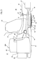
Fig. 3] Fig. 3 is a cross-sectional view ofFig. 2 in a vehicle front-rear direction showing a central region of a vehicle. - [
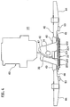
Fig. 4] Fig. 4 is a cross-sectional view ofFig. 2 in a vehicle width direction at a position where a power receiving portion is installed. - [
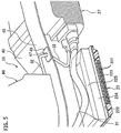
Fig. 5] Fig. 5 is a cross-sectional perspective view showing the power receiving portion arranged in a tunnel portion. - [
Fig. 6] Fig. 6 is a perspective view of the power receiving portion. - [
Fig. 7] Fig. 7 is a plan view showing the installation layout of the battery, the power receiving portion and the motor unit. - [
Fig. 8] Fig. 8 is a bottom view of the installation layout ofFig. 7 as viewed from the bottom of the vehicle. - [
Fig. 9] Fig. 9 is a cross-sectional view of installation examples (A) and (B) of the power receiving portion. - [
Fig. 10] Fig. 10 is a schematic view of wiring pattern examples (A), (B), (C) and (D) of the battery. - Hereinafter, an embodiment of the present invention will be explained in detail with reference to the drawings. It should be noted that dimensional ratios in the drawings are magnified for convenience of explanation and may be different from actual ratios.
- A contactless power supply device according to the present invention shown in
Fig. 1 includes apower supply device 100 as a ground-side unit and apower receiving device 200 as a vehicle-side unit. The contactless power supply device supplies electric power, without contact, from thepower supply device 100 located at a power supply stand or the like to thepower receiving device 200 installed in a vehicle 1 represented by an electric vehicle or a hybrid vehicle so as to charge abattery 27. - The
power supply device 100 includes apower supply portion 12 placed in aparking space 2 adjacent to the power supply stand. Thepower receiving device 200 includes apower receiving portion 22 placed on a bottom surface of the vehicle 1 in such a manner as to face thepower supply portion 12 when the vehicle 1 is parked at a predetermined position in theparking space 2. - A power transmission coil mainly composed of a primary coil made of an electrically conductive wire may be used as the
power supply portion 12. Similarly, a power receiving coil mainly composed of a secondary coil made of an electrically conductive wire may be used as thepower receiving portion 22. Electric power can be supplied from thepower supply portion 12 to thepower receiving portion 22 without contact by electromagnetic induction between the two coils. - The
power supply device 100 on the ground side includes apower controller 11, thepower supply portion 12, awireless communication unit 13, and acontroller 14. - The
power controller 11 converts AC power transmitted from anAC power source 300 to high-frequency AC power to transmit the converted power to thepower supply portion 12. Thepower controller 11 includes arectifier 111, a power factor correction (PFC)circuit 112, aninverter 113, and asensor 114. Therectifier 111 is a circuit electrically connected to theAC power source 300 to rectify the AC power output from theAC power source 300. ThePFC circuit 112 corrects power factor by shaping waveforms output from therectifier 111 and is connected between therectifier 111 and theinverter 113. - The
wireless communication unit 13 communicates interactive with awireless communication unit 23 provided on the vehicle 1. - The
controller 14 controls the entirepower supply device 100. Thecontroller 14 transmits a signal toward the vehicle 1 that thepower supply device 100 starts supplying electric power, or receives a signal from the vehicle 1 that power supply from thepower supply device 100 is requested, through the communication between the twowireless communication units - The
controller 14 further performs switching control on theinverter 113 depending on current detected by thesensor 114 so as to regulate electric power transmitted from thepower supply portion 12. In addition, thecontroller 14 stops power supply depending on a detection signal from aforeign object sensor 15 during power supply or transmits a warning signal toward the vehicle 1 via thewireless communication units - For example, a metal detection coil is used as the
foreign object sensor 15. When metal foreign objects enter or exist in a magnetic field formed between thepower supply portion 12 and thepower receiving portion 22 during power supply, thecontroller 14 immediately warns against or stops supplying electric power according to an electric detection signal from theforeign object sensor 15, so as to prevent a fault such as failure in power supply derived from the presence of the metal foreign objects in the magnetic field. - The
power receiving device 200 on the vehicle 1 side includes thepower receiving portion 22, thewireless communication unit 23, acharge controller 24, arectifier 25, arelay 26, thebattery 27, aninverter 28, amotor 29, and a notifyingunit 30. - The
power receiving portion 22 is located just above thepower supply portion 12 to face each other when the vehicle 1 is parked at a predetermined stop position in theparking space 2 as described below and kept separate from thepower supply portion 12. - The
rectifier 25 includes a rectifying circuit connected to thepower receiving portion 22 to rectify AC power received by thepower receiving portion 22 to DC power. - The
relay 26 includes a relay switch turned on/off based on the control by thecharge controller 24. Therelay 26 separates a main circuit system including thebattery 27 from thepower receiving portion 22 and therectifier 25 serving as a circuit for charging when the relay switch is turned off. - The
battery 27 includes a plurality of secondary batteries connected to each other and serves as a power source of the vehicle 1. Theinverter 28 is, for example, a PWM control circuit having a switching device such as an IGBT and converts DC power output from thebattery 27 to AC power to supply it to themotor 29 according to a switching control signal. Themotor 29 is, for example, a three-phase AC motor serving as a drive power source for driving the vehicle 1. - The notifying
unit 30 includes a warning lamp, a display of a navigation system or a speaker and outputs light, images or sounds and the like to a user based on the control of thecharge controller 24. - The
charge controller 24 regulates charge of thebattery 27 and controls thewireless communication unit 23, the notifyingunit 30, therelay 26 and the like. Thecharge controller 24 transmits a signal to start charging thebattery 27 to thecontroller 14 through the communication between the twowireless communication units charge controller 24 is connected to a controller (not shown in the figure) for controlling the entire vehicle 1 via a CAN communication network. This controller manages the switching control of theinverter 28 and the state of charge (SOC) of thebattery 27. When the SOC of thebattery 27 reaches full charge according to the controller, thecharge controller 24 transmits a signal to stop charging thebattery 27 to thecontroller 14. - The contactless power supply device according to the present embodiment transmits and receives high-frequency power between the
power supply portion 12 and thepower receiving portion 22 without contact by electromagnetic induction. In other words, once voltage is applied to thepower supply portion 12, magnetic connection is caused between thepower supply portion 12 and thepower receiving portion 22 so as to supply electric power from thepower supply portion 12 to thepower receiving portion 22. - Here, surfaces of protection casings of the respective
power supply portion 12 andpower receiving portion 22 facing each other serve as electromagnetic induction areas and are formed of a synthetic resin material in order not to obstruct the electromagnetic induction therebetween. -
Fig. 2 to Fig. 10 each show an installation state of thepower receiving portion 22 and thebattery 27 on the vehicle 1. - The
power receiving portion 22 and thebattery 27 are both installed on the lower surface of afloor panel 40 of the vehicle 1. - The
power receiving portion 22 is installed at a front end on the lower surface of thefloor panel 40 and in the middle in the vehicle width direction. Thebattery 27 is installed to cover a wide area from around the rear side of the installed position of thepower receiving portion 22 toward the rear of the vehicle. - The
floor panel 40 is connected to adash panel 41 located at the front end thereof to separate afront compartment 1F from aninterior room 1R. Thefloor panel 40 includes, in the middle thereof in the vehicle width direction (in the center of the vehicle), atunnel portion 42 protruding toward theinterior room 1R and extending in the vehicle front-rear direction (refer toFig. 2 andFig. 3 ). - The
tunnel portion 42 is provided withreinforcements 43 having a closed cross section extending along the base of protrusion in the vehicle front-rear direction on both sides of thetunnel portion 42. - The
floor panel 40 ensures necessary floor rigidity due to floor frame members including thetunnel portion 42 and thereinforcements 43 thereof,side sills 44, a plurality ofcross members 45 extending in the vehicle width direction, andoutriggers 46 and the like (refer toFig. 2 to Fig. 4 ). Theside sills 44 extend in the vehicle front-rear direction on both sides in the vehicle width direction. Theoutriggers 46 are located on the floor front side to connect thereinforcements 43 and theside sills 44 adjacent thereto. - The large and
heavy battery 27 is thus rigidly fixed to the main frame members such as theside sills 44 and thecross members 45 and to thereinforcements 43 of thetunnel portion 42. - The
power receiving portion 22 is elongated across a lower open portion of thetunnel portion 42 and connected thereto at the installed position as described above, namely on the lower surface at the front end of thefloor panel 40 and in the middle in the vehicle width direction (refer toFig. 4 ). - The
power receiving portion 22 has a width W2 in the vehicle width direction set to be larger than a width W1 of the lower open portion of the tunnel portion 42 (W1<W2). As shown inFigs. 9(A) and 9(B) , thepower receiving portion 22 is elongated across thereinforcements tunnel portion 42 or across theoutriggers - The
power receiving portion 22 is formed into a square plate shape and includes acoil body 221 for receiving electric power, aprotection casing 222 formed of nonmagnetic metal such as aluminum and housing thecoil body 221 fixed thereto, and alid 223 blocking the lower open portion of theprotection casing 222. Thelid 223 is formed of an appropriate synthetic resin material because of the reason described above in order not to obstruct the electromagnetic induction between thepower supply portion 12 and the power receiving portion 22 (refer toFig. 5 andFig. 6 ). - The
protection casing 222 is provided, in the middle on the upper surface thereof, with ajunction box 225 housing a switchboard (a distribution device), a relay (the relay 26) and a controller (the charge controller 24). In the examples shown inFig. 5 andFig. 6 , anelectrical box 224 housing electrical components such as a rectifier (the rectifier 25) and a capacitor is provided in the middle on the upper surface of theprotection casing 222. Thejunction box 225 is formed separately from theelectrical box 224 in such a manner as to have the same size on a projection plane and is removably attached on theelectrical box 224. - The
electrical box 224 is formed integrally with theprotection casing 222 and is separated inside thereof from the storage portion of thecoil body 221 by a partition plate. However, theelectrical box 224 may be formed separately from theprotection casing 222. - The
front compartment 1F is provided, on both sides in the vehicle width direction, withfront side members 50 serving as frame members at a front portion of the vehicle body and extending in the vehicle front-rear direction with rear ends thereof connected to thedash panel 41. - The
front compartment 1F is provided with asub frame 51 on the lower side thereof, on which amotor unit 29U including theinverter 28 and themotor 29 described above is mounted and fixed via amount member 52. - The
sub frame 51 is formed substantially into a rectangular shape in a plan view, and front and rear ends thereof on both sides in the vehicle width direction are connected to lower surfaces at front and rear ends of the right and leftfront side members 50 so as to serve as frame members of the vehicle body on the lower side of thefront compartment 1F. - The
sub frame 51 includesextensions 53 at the rear end thereof extending toward the rear of the vehicle on both sides of thepower receiving portion 22 in the vehicle width direction to reinforce the portions to which thepower receiving portion 22 is fixed (refer toFig. 7 andFig. 8 ). In the examples shown in the figures, theextensions 53 are formed separately from thesub frame 51 in such a manner as to have base portions elongated in the vehicle width direction and extending portions extending from the base portions on both sides toward the rear of the vehicle. The base portions are fastened together with the rear end of thesub frame 51, and the rear ends of the extensions are connected to theoutriggers 46. However, the extensions may be formed integrally with thesub frame 51. - The installation layout includes the
battery 27, thepower receiving portion 22 and themotor unit 29U aligned in line in the vehicle front-rear direction. A high-currentsystem wire harness 31 for transmitting electric power from thebattery 27 to themotor unit 29U passes above thepower receiving portion 22 and is arranged along the inside of thetunnel portion 42. Thewire harness 31 is connected to each of the front end of thebattery 27 and the rear end of themotor unit 29U (the rear end of the inverter 28) with connectors. - The
wire harness 31 is arranged above thejunction box 225 but may be arranged on one side of thejunction box 225 as necessary. In such a case, theelectrical box 224 and thejunction box 225 may be shifted toward the outer side from the central position of thetunnel portion 42 so as to ensure a wiring space for thewire harness 31 having a large diameter. - The top wall of the
tunnel portion 42 is provided with a through-hole 47 adjacent to thejunction box 225. A high-currentsystem wire harness 32 is inserted into the through-hole 47 to transmit electric power therethrough from thebattery 27 or thejunction box 225 to aroom accessory 60 such as an air conditioning unit installed inside theinterior room 1R. Agrommet 48 is fitted into the through-hole 47 to seal the circumference of the wire harness inserted thereinto. -
Fig. 10 shows examples (A) to (D) of different wiring patterns for power transmission from thebattery 27 to themotor unit 29U and theroom accessory 60. -
Fig. 10(A) shows an example in which thebattery 27 is connected to themotor unit 29U, theroom accessory 60 and thejunction box 225 with the respective wire harnesses 31, 32 and 33. -
Fig. 10(B) shows an example in which thewire harness 32 shown inFig. 10(A) is distributed from thejunction box 225 and connected to theroom accessory 60, which decreases one wire extending from thebattery 27. -
Fig. 10(C) shows an example in which thewire harness 31 shown inFig. 10(B) is distributed from thejunction box 225 and connected to themotor unit 29U so as to omit thewire harness 33, which decreases two wires extending from thebattery 27. -
Fig. 10(D) shows an example in which thejunction box 225 is separated from thepower receiving portion 22 and installed in the interior room so as to increase the space inside thetunnel portion 42. Thewire harness 33 shown inFig. 10(A) and awire harness 34 connecting thepower receiving portion 22 and thejunction box 225 are inserted into the above-described through-hole 47 together with thewire harness 32. - According to the contactless power supply device of the present embodiment having the configuration described above, the
power receiving portion 22 is installed in the middle in the vehicle width direction at the front end on the lower surface of thefloor panel 40 close to the front wheels W to be steered. Therefore, the vehicle 1 is only required to be steered in such a manner as to align the center thereof with thepower supply portion 12 on the road surface side when the vehicle 1 is parked at a predetermined stop position in theparking space 2 so as to accurately align thepower receiving portion 22 with thepower supply portion 12 to face each other with a sense of steering the vehicle 1. In addition, since thepower receiving portion 22 is located close to the front wheels W to be steered, a fine adjustment to the position of thepower supply portion 12 can be made so that thepower receiving portion 22 can be aligned with thepower supply portion 12 to face each other more accurately. - Accordingly, a dedicated drive control system for the
power supply portion 12 having a movable configuration using a driving mechanism is not required for the accurate alignment described above. As a result, thepower receiving portion 22 can be aligned with thepower supply portion 12 to face each other with a simple driving operation of the vehicle 1 while providing a cost advantage. - Further, the
power receiving portion 22 covers the lower side of the high-currentsystem wire harness 31 for transmitting electric power from thebattery 27 placed on the lower surface of thefloor panel 40 to themotor unit 29U in thefront compartment 1F so that thepower receiving portion 22 serves as a protector to improve the safety of thewire harness 31. - Moreover, the
power receiving portion 22 is located in the center of the vehicle with the installation layout including thebattery 27, thepower receiving portion 22 and themotor unit 29U aligned in line in the vehicle front-rear direction, and thewire harness 31 is arranged and passes straight above thepower receiving portion 22 in a plan view so as to decrease the length of thewire harness 31. - The
floor panel 40 described above includes thetunnel portion 42 in the center of the vehicle (in the middle in the vehicle width direction). Thepower receiving portion 22 described above is elongated across the lower open portion of thetunnel portion 42, and thewire harness 31 is arranged along the inside of thetunnel portion 42. - The
power receiving portion 22 has a square plate-shaped rigid-body structure housing thecoil body 221 between theprotection casing 222 formed of metal and thelid 223 formed of synthetic resin as above described so as to increase the rigidity of the lower open portion of thetunnel portion 42 to prevent stretch deformation (opening extension). Furthermore, thewire harness 31 can be stored in the closed cross section defined by thepower receiving portion 22 and thetunnel portion 42 so as to further improve the safety of thewire harness 31. - The
power receiving portion 22 includes thejunction box 225 on the upper surface thereof. Since thepower receiving portion 22 is elongated across the lower open portion of thetunnel portion 42 as described above, thejunction box 225 is located inside thetunnel portion 42 so that the safety of thejunction box 225 can be improved. - Since the
junction box 225 projecting on the upper surface of thepower receiving portion 22 is located inside thetunnel portion 42, an upward increase in height of thefloor panel 42 can be prevent so as to favorably design the vehicle body. - The
junction box 225 is formed separately from thepower receiving portion 22 and removably attached on the upper surface of thepower receiving portion 22. Therefore, thejunction box 225 may be removed therefrom and installed inside the interior room as shown inFig. 10(D) depending on specifications. Particularly, in specifications of a hybrid vehicle, such an installation allows a longitudinal arrangement of an exhaust gas tube inside thetunnel portion 42 so as to share the lower structure of the vehicle body. - The
tunnel portion 42 is provided with the through-hole 47 on the top wall thereof. Therefore, thewire harness 32 or the like passing therethrough can connect thebattery 27 or thejunction box 225 to theroom accessory 60 installed in theinterior room 1 R with the shortest distance therebetween so as to expand the possibility of the wiring layout. - The
tunnel portion 42 is provided with thereinforcements 43 having a closed cross section extending along the base of protrusion in the vehicle front-rear direction on both sides of thetunnel portion 42. Since thepower receiving portion 22 is elongated across thesereinforcements 43, both the attachment rigidity of thepower receiving portion 22 and the rigidity of the lower open portion of thetunnel portion 42 in the vehicle width direction can be improved. - The
power receiving portion 22 has the width W2 in the vehicle width direction set to be larger than the width W1 of the lower open portion of thetunnel portion 42 and is directly connected to thereinforcements 43 located on both sides of the lower open portion. Therefore, the attachment rigidity and the rigidity in the vehicle width direction described above can be further improved. - The
motor unit 29U is installed on thesub frame 51 serving as a frame member located on the lower side of thefront compartment 1F. Thesub frame 51 includes theextensions 53 at the rear end thereof extending on both sides of thepower receiving portion 22 in the vehicle width direction toward the rear of the vehicle to reinforce the portions to which thepower receiving portion 22 is fixed. - The effect due to the
extensions 53 to reinforce the portions to which thepower receiving portion 22 is fixed can increase the attachment rigidity of thepower receiving portion 22 against vibration input acting on the fixed portions caused by vibrations during driving and the like. In addition, the front side and both right and left sides of thepower receiving portion 22 can be protected by the rear end of thesub frame 51 and theextensions 53 located on both sides thereof, and the rear side of thepower receiving portion 22 can be protected by thebattery 27. - Accordingly, the
power receiving portion 22 can be preserved from interference from road surfaces or the like and at the same time, the effect of protecting the above-describedwire harness 31 arranged above thepower receiving portion 22 can be increased. - Although the embodiment described above exemplified the case where the width W2 of the
power receiving portion 22 in the vehicle width direction and the width W1 of the lower open portion of thetunnel portion 42 satisfy the relationship of W1<W2, the relationship may be changed to W1>W2 depending on vehicle specifications. In such a case, thepower receiving portion 22 may be elongated across the lower open portion of thetunnel portion 42 and connected thereto via brackets. - Further, the embodiment described above exemplified the case where the
floor panel 40 is provided with thetunnel portion 42 in the center of the vehicle but may also be applied to a case where a floor of a flat type without thetunnel portion 42 is used. - The entire content of Japanese Patent Application No.
P2013-083542 (filed on April 12, 2013 - Although the present invention has been described above by reference to the embodiment, the present invention is not limited to the descriptions thereof, and it will be apparent to those skilled in the art that various modifications and improvements can be made.
- According to the present invention, the power receiving portion is installed at the front portion on the lower surface of the floor panel close to the steered front wheels and located in the middle in the vehicle width direction. Therefore, the power receiving portion can be accurately aligned with the power supply portion to face each other with a sense of steering in such a manner as to align the center of the vehicle with the power supply portion on the load surface side when the vehicle is parked at a predetermined stop position in the parking space. Moreover, the power receiving portion covers the lower side of the high-current system wire harness for transmitting electric power from the battery located on the lower surface of the floor panel to the motor unit in the front compartment so that the power receiving portion serves as a protector to improve the safety of the wire harness.
-
- 1
- VEHICLE
- 1F
- FRONT COMPARTMENT
- 1R
- INTERIOR ROOM
- 12
- POWER SUPPLY PORTION
- 22
- POWER RECEIVING PORTION
- 27
- BATTERY
- 29U
- MOTOR UNIT
- 31, 32, 33, 34
- WIRE HARNESS
- 40
- FLOOR PANEL
- 42
- TUNNEL PORTION
Claims (2)
- A contactless power supply device comprising:a power receiving portion placed in a middle in a vehicle width direction at a front portion on a lower surface of a floor panel of a vehicle;a power supply portion located in a parking space to supply electric power to the vehicle without contact through magnetic connection between the power supply portion and the power receiving portion;a battery placed on the floor panel; anda wire harness for transmitting electric power from the battery to a motor unit placed in a front compartment of the vehicle, the wire harness passing above the power receiving portion and extending in a vehicle front-rear direction.
- The contactless power supply device according to claim 1, wherein:the floor panel includes, in a middle thereof in the vehicle width direction, a tunnel portion protruding toward an interior room and extending in the vehicle front-rear direction;the power receiving portion is elongated across a lower open portion of the tunnel portion; andthe wire harness is arranged along an inside of the tunnel portion.
Applications Claiming Priority (2)
| Application Number | Priority Date | Filing Date | Title |
|---|---|---|---|
| JP2013083542 | 2013-04-12 | ||
| PCT/JP2014/057770 WO2014167976A1 (en) | 2013-04-12 | 2014-03-20 | Contactless power-supply device |
Publications (3)
| Publication Number | Publication Date |
|---|---|
| EP2985188A1 true EP2985188A1 (en) | 2016-02-17 |
| EP2985188A4 EP2985188A4 (en) | 2016-06-15 |
| EP2985188B1 EP2985188B1 (en) | 2021-06-02 |
Family
ID=51689388
Family Applications (1)
| Application Number | Title | Priority Date | Filing Date |
|---|---|---|---|
| EP14782732.3A Active EP2985188B1 (en) | 2013-04-12 | 2014-03-20 | Contactless power-supply device |
Country Status (10)
| Country | Link |
|---|---|
| US (1) | US10144300B2 (en) |
| EP (1) | EP2985188B1 (en) |
| JP (1) | JP6352902B2 (en) |
| KR (1) | KR20150125991A (en) |
| CN (1) | CN105121229B (en) |
| BR (1) | BR112015025964B1 (en) |
| MX (1) | MX358895B (en) |
| MY (1) | MY178004A (en) |
| RU (1) | RU2652360C2 (en) |
| WO (1) | WO2014167976A1 (en) |
Cited By (2)
| Publication number | Priority date | Publication date | Assignee | Title |
|---|---|---|---|---|
| DE102017119128A1 (en) | 2017-08-22 | 2019-02-28 | Dr. Ing. H.C. F. Porsche Aktiengesellschaft | Body structure of an electric vehicle and electric vehicle |
| EP3575128A4 (en) * | 2017-01-30 | 2020-02-12 | Nissan Motor Co., Ltd. | VEHICLE MOUNTING STRUCTURE FOR NON-CONTACT ENERGY RECEIVING DEVICE |
Families Citing this family (12)
| Publication number | Priority date | Publication date | Assignee | Title |
|---|---|---|---|---|
| JP3508771B2 (en) | 2003-04-18 | 2004-03-22 | 松下電工株式会社 | Massage chair |
| JP6043462B2 (en) * | 2012-09-27 | 2016-12-14 | Ihi運搬機械株式会社 | Vehicle power supply device |
| JP6160083B2 (en) * | 2013-01-08 | 2017-07-12 | 株式会社Ihi | Foreign object detection device |
| WO2014167979A1 (en) | 2013-04-12 | 2014-10-16 | 日産自動車株式会社 | Contactless power supply device |
| US10041449B2 (en) | 2015-09-25 | 2018-08-07 | Ford Global Technologies, Llc | Evaporative emissions testing using inductive heating |
| DE102016203209B4 (en) * | 2016-02-29 | 2020-11-19 | Ford Global Technologies, Llc | At least partially electrically operated motor vehicle |
| JP2019051817A (en) * | 2017-09-15 | 2019-04-04 | 本田技研工業株式会社 | vehicle |
| JP6935756B2 (en) * | 2018-01-30 | 2021-09-15 | トヨタ自動車株式会社 | Vehicle front structure |
| CN112567592A (en) * | 2018-08-21 | 2021-03-26 | 三菱电机株式会社 | Contactless power supply system, power receiving device for contactless power supply, and activation signal transmission method for power receiving device for contactless power supply |
| JP7110974B2 (en) * | 2018-12-26 | 2022-08-02 | 株式会社オートネットワーク技術研究所 | Power supply system and automobile |
| JP2021011262A (en) * | 2020-10-09 | 2021-02-04 | 本田技研工業株式会社 | vehicle |
| CN119329281A (en) * | 2023-07-18 | 2025-01-21 | 本田技研工业株式会社 | Drive unit |
Family Cites Families (33)
| Publication number | Priority date | Publication date | Assignee | Title |
|---|---|---|---|---|
| JPS6467443A (en) * | 1987-09-08 | 1989-03-14 | Honda Motor Co Ltd | Cable structure |
| JPH07322447A (en) | 1994-05-19 | 1995-12-08 | Daihatsu Motor Co Ltd | Harness laying structure |
| JPH10109548A (en) * | 1996-10-09 | 1998-04-28 | Suzuki Motor Corp | Battery fitting structure for electric vehicle |
| JP4120157B2 (en) | 2000-11-29 | 2008-07-16 | スズキ株式会社 | Vehicle floor structure |
| JP2005029103A (en) * | 2003-07-11 | 2005-02-03 | Mazda Motor Corp | Vehicle body structure |
| JP2005306104A (en) * | 2004-04-19 | 2005-11-04 | Nissan Motor Co Ltd | Fuel cell automobile |
| JP4151636B2 (en) * | 2004-10-06 | 2008-09-17 | 日産自動車株式会社 | Hybrid vehicle |
| US7896115B2 (en) * | 2005-07-08 | 2011-03-01 | Honda Motor Co., Ltd. | Fuel cell vehicle |
| FR2925406B1 (en) | 2007-12-21 | 2010-01-08 | Peugeot Citroen Automobiles Sa | CABLE GUIDING DEVICE FOR MOUNTING HIGH-POSITION SPEED CONTROL |
| JP2010004649A (en) | 2008-06-19 | 2010-01-07 | Honda Motor Co Ltd | Ventilator of fuel cell vehicle |
| RU2469880C1 (en) * | 2008-09-25 | 2012-12-20 | Тойота Дзидося Кабусики Кайся | Power supply system and electrically driven vehicle |
| US8598743B2 (en) * | 2008-09-27 | 2013-12-03 | Witricity Corporation | Resonator arrays for wireless energy transfer |
| US20110074346A1 (en) * | 2009-09-25 | 2011-03-31 | Hall Katherine L | Vehicle charger safety system and method |
| JP5606098B2 (en) * | 2009-02-25 | 2014-10-15 | マスプロ電工株式会社 | Mobile power supply system |
| JP4868089B2 (en) | 2009-03-18 | 2012-02-01 | トヨタ自動車株式会社 | Non-contact power receiving device, non-contact power transmission device, non-contact power feeding system and vehicle |
| KR20120018336A (en) * | 2009-05-22 | 2012-03-02 | 닛산 지도우샤 가부시키가이샤 | Vehicle component mounting arrangement |
| JP5640382B2 (en) * | 2009-05-26 | 2014-12-17 | 日産自動車株式会社 | Vehicle battery assembly cooling structure and battery assembly with water jacket |
| FR2947114B1 (en) * | 2009-06-17 | 2014-09-19 | Renault Sas | CHARGING A BATTERY OF A MOTOR VEHICLE |
| KR20110060207A (en) | 2009-11-30 | 2011-06-08 | 현대자동차일본기술연구소 | Contactless Charging Stations for Electric Vehicles |
| CN102695629B (en) * | 2010-01-05 | 2015-03-25 | 捷通国际有限公司 | Inductive charging system for electric vehicle |
| WO2011116394A1 (en) | 2010-03-19 | 2011-09-22 | Fisker Automotive, Inc. | Wireless charging device for electric and plug-in hybrid vehicles |
| JP2011217452A (en) | 2010-03-31 | 2011-10-27 | Honda Motor Co Ltd | Contactless charging system |
| US10343535B2 (en) * | 2010-04-08 | 2019-07-09 | Witricity Corporation | Wireless power antenna alignment adjustment system for vehicles |
| JP2011250593A (en) * | 2010-05-27 | 2011-12-08 | Toyota Motor Corp | Vehicle |
| JP2012034468A (en) | 2010-07-29 | 2012-02-16 | Toyota Industries Corp | Resonance type non-contact power feeding system for vehicle |
| US8800738B2 (en) * | 2010-12-28 | 2014-08-12 | Tdk Corporation | Wireless power feeder and wireless power receiver |
| JP5776703B2 (en) * | 2011-02-04 | 2015-09-09 | トヨタ自動車株式会社 | Vehicle and external power supply device |
| DE112011105218B4 (en) * | 2011-02-23 | 2019-12-19 | Suzuki Motor Corp. | Cable routing structure for a high-voltage cable of a vehicle |
| JP6012143B2 (en) | 2011-05-17 | 2016-10-25 | 日産自動車株式会社 | Electric vehicle charging / discharging harness wiring structure |
| EP2752324B1 (en) | 2011-08-30 | 2018-06-27 | Toyota Jidosha Kabushiki Kaisha | Vehicle |
| JP5659306B2 (en) * | 2011-11-17 | 2015-01-28 | 本田技研工業株式会社 | Electric vehicle |
| JP5810944B2 (en) * | 2012-01-31 | 2015-11-11 | トヨタ自動車株式会社 | Vehicle and power transmission system |
| WO2014167979A1 (en) * | 2013-04-12 | 2014-10-16 | 日産自動車株式会社 | Contactless power supply device |
-
2014
- 2014-03-20 RU RU2015148438A patent/RU2652360C2/en active
- 2014-03-20 CN CN201480020937.3A patent/CN105121229B/en active Active
- 2014-03-20 WO PCT/JP2014/057770 patent/WO2014167976A1/en not_active Ceased
- 2014-03-20 EP EP14782732.3A patent/EP2985188B1/en active Active
- 2014-03-20 MY MYPI2015703587A patent/MY178004A/en unknown
- 2014-03-20 MX MX2015013961A patent/MX358895B/en active IP Right Grant
- 2014-03-20 US US14/783,843 patent/US10144300B2/en active Active
- 2014-03-20 JP JP2015511177A patent/JP6352902B2/en active Active
- 2014-03-20 KR KR1020157027053A patent/KR20150125991A/en not_active Ceased
- 2014-03-20 BR BR112015025964-2A patent/BR112015025964B1/en not_active IP Right Cessation
Cited By (4)
| Publication number | Priority date | Publication date | Assignee | Title |
|---|---|---|---|---|
| EP3575128A4 (en) * | 2017-01-30 | 2020-02-12 | Nissan Motor Co., Ltd. | VEHICLE MOUNTING STRUCTURE FOR NON-CONTACT ENERGY RECEIVING DEVICE |
| US10870354B2 (en) | 2017-01-30 | 2020-12-22 | Nissan Motor Co., Ltd. | Vehicle-mounting structure for contactless power reception device |
| DE102017119128A1 (en) | 2017-08-22 | 2019-02-28 | Dr. Ing. H.C. F. Porsche Aktiengesellschaft | Body structure of an electric vehicle and electric vehicle |
| DE102017119128B4 (en) | 2017-08-22 | 2019-07-04 | Dr. Ing. H.C. F. Porsche Aktiengesellschaft | Body structure of an electric vehicle and electric vehicle |
Also Published As
| Publication number | Publication date |
|---|---|
| JP6352902B2 (en) | 2018-07-04 |
| US10144300B2 (en) | 2018-12-04 |
| RU2015148438A (en) | 2017-05-17 |
| WO2014167976A1 (en) | 2014-10-16 |
| MX358895B (en) | 2018-09-07 |
| CN105121229A (en) | 2015-12-02 |
| MY178004A (en) | 2020-09-29 |
| RU2652360C2 (en) | 2018-04-25 |
| BR112015025964B1 (en) | 2021-12-14 |
| EP2985188B1 (en) | 2021-06-02 |
| KR20150125991A (en) | 2015-11-10 |
| US20160082847A1 (en) | 2016-03-24 |
| CN105121229B (en) | 2018-11-13 |
| BR112015025964A2 (en) | 2020-05-05 |
| MX2015013961A (en) | 2016-02-10 |
| JPWO2014167976A1 (en) | 2017-02-16 |
| EP2985188A4 (en) | 2016-06-15 |
Similar Documents
| Publication | Publication Date | Title |
|---|---|---|
| US9539908B2 (en) | Contactless power supply device | |
| EP2985188B1 (en) | Contactless power-supply device | |
| US9415697B2 (en) | Contactless power supply system | |
| JP6291769B2 (en) | Contactless power supply | |
| US9725004B2 (en) | Vehicle mounting structure of contactless power reception device | |
| EP3061643B1 (en) | Vehicle mounting structure of contactless electricity reception device | |
| KR102151500B1 (en) | Vehicle-mounted structure of non-contact power receiving device | |
| WO2014167977A1 (en) | Contactless power supply device | |
| JP2014113862A (en) | Junction box for vehicle |
Legal Events
| Date | Code | Title | Description |
|---|---|---|---|
| PUAI | Public reference made under article 153(3) epc to a published international application that has entered the european phase |
Free format text: ORIGINAL CODE: 0009012 |
|
| 17P | Request for examination filed |
Effective date: 20151007 |
|
| AK | Designated contracting states |
Kind code of ref document: A1 Designated state(s): AL AT BE BG CH CY CZ DE DK EE ES FI FR GB GR HR HU IE IS IT LI LT LU LV MC MK MT NL NO PL PT RO RS SE SI SK SM TR |
|
| AX | Request for extension of the european patent |
Extension state: BA ME |
|
| A4 | Supplementary search report drawn up and despatched |
Effective date: 20160518 |
|
| RIC1 | Information provided on ipc code assigned before grant |
Ipc: B60K 1/04 20060101ALI20160511BHEP Ipc: B62D 25/20 20060101ALI20160511BHEP Ipc: B60R 16/03 20060101AFI20160511BHEP Ipc: B60L 11/18 20060101ALI20160511BHEP Ipc: H02J 50/00 20160101ALI20160511BHEP Ipc: B60L 5/00 20060101ALI20160511BHEP Ipc: H02J 7/00 20060101ALI20160511BHEP |
|
| DAX | Request for extension of the european patent (deleted) | ||
| STAA | Information on the status of an ep patent application or granted ep patent |
Free format text: STATUS: EXAMINATION IS IN PROGRESS |
|
| 17Q | First examination report despatched |
Effective date: 20200513 |
|
| REG | Reference to a national code |
Ref country code: DE Ref legal event code: R079 Ref document number: 602014077904 Country of ref document: DE Free format text: PREVIOUS MAIN CLASS: B60R0016030000 Ipc: B60L0053120000 |
|
| GRAP | Despatch of communication of intention to grant a patent |
Free format text: ORIGINAL CODE: EPIDOSNIGR1 |
|
| STAA | Information on the status of an ep patent application or granted ep patent |
Free format text: STATUS: GRANT OF PATENT IS INTENDED |
|
| RIC1 | Information provided on ipc code assigned before grant |
Ipc: B60L 53/122 20190101ALI20210114BHEP Ipc: B60L 53/36 20190101ALI20210114BHEP Ipc: B60L 53/12 20190101AFI20210114BHEP Ipc: B60L 50/60 20190101ALI20210114BHEP Ipc: B60L 53/38 20190101ALI20210114BHEP |
|
| INTG | Intention to grant announced |
Effective date: 20210212 |
|
| GRAS | Grant fee paid |
Free format text: ORIGINAL CODE: EPIDOSNIGR3 |
|
| GRAA | (expected) grant |
Free format text: ORIGINAL CODE: 0009210 |
|
| STAA | Information on the status of an ep patent application or granted ep patent |
Free format text: STATUS: THE PATENT HAS BEEN GRANTED |
|
| REG | Reference to a national code |
Ref country code: CH Ref legal event code: EP |
|
| AK | Designated contracting states |
Kind code of ref document: B1 Designated state(s): AL AT BE BG CH CY CZ DE DK EE ES FI FR GB GR HR HU IE IS IT LI LT LU LV MC MK MT NL NO PL PT RO RS SE SI SK SM TR |
|
| REG | Reference to a national code |
Ref country code: GB Ref legal event code: FG4D |
|
| REG | Reference to a national code |
Ref country code: AT Ref legal event code: REF Ref document number: 1398139 Country of ref document: AT Kind code of ref document: T Effective date: 20210615 |
|
| REG | Reference to a national code |
Ref country code: IE Ref legal event code: FG4D |
|
| REG | Reference to a national code |
Ref country code: DE Ref legal event code: R096 Ref document number: 602014077904 Country of ref document: DE |
|
| REG | Reference to a national code |
Ref country code: LT Ref legal event code: MG9D |
|
| PG25 | Lapsed in a contracting state [announced via postgrant information from national office to epo] |
Ref country code: BG Free format text: LAPSE BECAUSE OF FAILURE TO SUBMIT A TRANSLATION OF THE DESCRIPTION OR TO PAY THE FEE WITHIN THE PRESCRIBED TIME-LIMIT Effective date: 20210902 Ref country code: FI Free format text: LAPSE BECAUSE OF FAILURE TO SUBMIT A TRANSLATION OF THE DESCRIPTION OR TO PAY THE FEE WITHIN THE PRESCRIBED TIME-LIMIT Effective date: 20210602 Ref country code: LT Free format text: LAPSE BECAUSE OF FAILURE TO SUBMIT A TRANSLATION OF THE DESCRIPTION OR TO PAY THE FEE WITHIN THE PRESCRIBED TIME-LIMIT Effective date: 20210602 Ref country code: HR Free format text: LAPSE BECAUSE OF FAILURE TO SUBMIT A TRANSLATION OF THE DESCRIPTION OR TO PAY THE FEE WITHIN THE PRESCRIBED TIME-LIMIT Effective date: 20210602 |
|
| REG | Reference to a national code |
Ref country code: NL Ref legal event code: MP Effective date: 20210602 |
|
| REG | Reference to a national code |
Ref country code: AT Ref legal event code: MK05 Ref document number: 1398139 Country of ref document: AT Kind code of ref document: T Effective date: 20210602 |
|
| PG25 | Lapsed in a contracting state [announced via postgrant information from national office to epo] |
Ref country code: NO Free format text: LAPSE BECAUSE OF FAILURE TO SUBMIT A TRANSLATION OF THE DESCRIPTION OR TO PAY THE FEE WITHIN THE PRESCRIBED TIME-LIMIT Effective date: 20210902 Ref country code: PL Free format text: LAPSE BECAUSE OF FAILURE TO SUBMIT A TRANSLATION OF THE DESCRIPTION OR TO PAY THE FEE WITHIN THE PRESCRIBED TIME-LIMIT Effective date: 20210602 Ref country code: RS Free format text: LAPSE BECAUSE OF FAILURE TO SUBMIT A TRANSLATION OF THE DESCRIPTION OR TO PAY THE FEE WITHIN THE PRESCRIBED TIME-LIMIT Effective date: 20210602 Ref country code: SE Free format text: LAPSE BECAUSE OF FAILURE TO SUBMIT A TRANSLATION OF THE DESCRIPTION OR TO PAY THE FEE WITHIN THE PRESCRIBED TIME-LIMIT Effective date: 20210602 Ref country code: GR Free format text: LAPSE BECAUSE OF FAILURE TO SUBMIT A TRANSLATION OF THE DESCRIPTION OR TO PAY THE FEE WITHIN THE PRESCRIBED TIME-LIMIT Effective date: 20210903 Ref country code: LV Free format text: LAPSE BECAUSE OF FAILURE TO SUBMIT A TRANSLATION OF THE DESCRIPTION OR TO PAY THE FEE WITHIN THE PRESCRIBED TIME-LIMIT Effective date: 20210602 |
|
| PG25 | Lapsed in a contracting state [announced via postgrant information from national office to epo] |
Ref country code: EE Free format text: LAPSE BECAUSE OF FAILURE TO SUBMIT A TRANSLATION OF THE DESCRIPTION OR TO PAY THE FEE WITHIN THE PRESCRIBED TIME-LIMIT Effective date: 20210602 Ref country code: CZ Free format text: LAPSE BECAUSE OF FAILURE TO SUBMIT A TRANSLATION OF THE DESCRIPTION OR TO PAY THE FEE WITHIN THE PRESCRIBED TIME-LIMIT Effective date: 20210602 Ref country code: SK Free format text: LAPSE BECAUSE OF FAILURE TO SUBMIT A TRANSLATION OF THE DESCRIPTION OR TO PAY THE FEE WITHIN THE PRESCRIBED TIME-LIMIT Effective date: 20210602 Ref country code: SM Free format text: LAPSE BECAUSE OF FAILURE TO SUBMIT A TRANSLATION OF THE DESCRIPTION OR TO PAY THE FEE WITHIN THE PRESCRIBED TIME-LIMIT Effective date: 20210602 Ref country code: AT Free format text: LAPSE BECAUSE OF FAILURE TO SUBMIT A TRANSLATION OF THE DESCRIPTION OR TO PAY THE FEE WITHIN THE PRESCRIBED TIME-LIMIT Effective date: 20210602 Ref country code: ES Free format text: LAPSE BECAUSE OF FAILURE TO SUBMIT A TRANSLATION OF THE DESCRIPTION OR TO PAY THE FEE WITHIN THE PRESCRIBED TIME-LIMIT Effective date: 20210602 Ref country code: NL Free format text: LAPSE BECAUSE OF FAILURE TO SUBMIT A TRANSLATION OF THE DESCRIPTION OR TO PAY THE FEE WITHIN THE PRESCRIBED TIME-LIMIT Effective date: 20210602 Ref country code: PT Free format text: LAPSE BECAUSE OF FAILURE TO SUBMIT A TRANSLATION OF THE DESCRIPTION OR TO PAY THE FEE WITHIN THE PRESCRIBED TIME-LIMIT Effective date: 20211004 Ref country code: RO Free format text: LAPSE BECAUSE OF FAILURE TO SUBMIT A TRANSLATION OF THE DESCRIPTION OR TO PAY THE FEE WITHIN THE PRESCRIBED TIME-LIMIT Effective date: 20210602 |
|
| REG | Reference to a national code |
Ref country code: DE Ref legal event code: R097 Ref document number: 602014077904 Country of ref document: DE |
|
| PLBE | No opposition filed within time limit |
Free format text: ORIGINAL CODE: 0009261 |
|
| STAA | Information on the status of an ep patent application or granted ep patent |
Free format text: STATUS: NO OPPOSITION FILED WITHIN TIME LIMIT |
|
| PG25 | Lapsed in a contracting state [announced via postgrant information from national office to epo] |
Ref country code: DK Free format text: LAPSE BECAUSE OF FAILURE TO SUBMIT A TRANSLATION OF THE DESCRIPTION OR TO PAY THE FEE WITHIN THE PRESCRIBED TIME-LIMIT Effective date: 20210602 |
|
| 26N | No opposition filed |
Effective date: 20220303 |
|
| PG25 | Lapsed in a contracting state [announced via postgrant information from national office to epo] |
Ref country code: AL Free format text: LAPSE BECAUSE OF FAILURE TO SUBMIT A TRANSLATION OF THE DESCRIPTION OR TO PAY THE FEE WITHIN THE PRESCRIBED TIME-LIMIT Effective date: 20210602 |
|
| PG25 | Lapsed in a contracting state [announced via postgrant information from national office to epo] |
Ref country code: IT Free format text: LAPSE BECAUSE OF FAILURE TO SUBMIT A TRANSLATION OF THE DESCRIPTION OR TO PAY THE FEE WITHIN THE PRESCRIBED TIME-LIMIT Effective date: 20210602 |
|
| PG25 | Lapsed in a contracting state [announced via postgrant information from national office to epo] |
Ref country code: MC Free format text: LAPSE BECAUSE OF FAILURE TO SUBMIT A TRANSLATION OF THE DESCRIPTION OR TO PAY THE FEE WITHIN THE PRESCRIBED TIME-LIMIT Effective date: 20210602 |
|
| REG | Reference to a national code |
Ref country code: CH Ref legal event code: PL |
|
| REG | Reference to a national code |
Ref country code: BE Ref legal event code: MM Effective date: 20220331 |
|
| PG25 | Lapsed in a contracting state [announced via postgrant information from national office to epo] |
Ref country code: LU Free format text: LAPSE BECAUSE OF NON-PAYMENT OF DUE FEES Effective date: 20220320 Ref country code: LI Free format text: LAPSE BECAUSE OF NON-PAYMENT OF DUE FEES Effective date: 20220331 Ref country code: IE Free format text: LAPSE BECAUSE OF NON-PAYMENT OF DUE FEES Effective date: 20220320 Ref country code: CH Free format text: LAPSE BECAUSE OF NON-PAYMENT OF DUE FEES Effective date: 20220331 |
|
| PG25 | Lapsed in a contracting state [announced via postgrant information from national office to epo] |
Ref country code: BE Free format text: LAPSE BECAUSE OF NON-PAYMENT OF DUE FEES Effective date: 20220331 |
|
| PG25 | Lapsed in a contracting state [announced via postgrant information from national office to epo] |
Ref country code: HU Free format text: LAPSE BECAUSE OF FAILURE TO SUBMIT A TRANSLATION OF THE DESCRIPTION OR TO PAY THE FEE WITHIN THE PRESCRIBED TIME-LIMIT; INVALID AB INITIO Effective date: 20140320 |
|
| PG25 | Lapsed in a contracting state [announced via postgrant information from national office to epo] |
Ref country code: MK Free format text: LAPSE BECAUSE OF FAILURE TO SUBMIT A TRANSLATION OF THE DESCRIPTION OR TO PAY THE FEE WITHIN THE PRESCRIBED TIME-LIMIT Effective date: 20210602 Ref country code: CY Free format text: LAPSE BECAUSE OF FAILURE TO SUBMIT A TRANSLATION OF THE DESCRIPTION OR TO PAY THE FEE WITHIN THE PRESCRIBED TIME-LIMIT Effective date: 20210602 |
|
| PG25 | Lapsed in a contracting state [announced via postgrant information from national office to epo] |
Ref country code: MT Free format text: LAPSE BECAUSE OF FAILURE TO SUBMIT A TRANSLATION OF THE DESCRIPTION OR TO PAY THE FEE WITHIN THE PRESCRIBED TIME-LIMIT Effective date: 20210602 |
|
| PG25 | Lapsed in a contracting state [announced via postgrant information from national office to epo] |
Ref country code: TR Free format text: LAPSE BECAUSE OF FAILURE TO SUBMIT A TRANSLATION OF THE DESCRIPTION OR TO PAY THE FEE WITHIN THE PRESCRIBED TIME-LIMIT Effective date: 20210602 |
|
| PGFP | Annual fee paid to national office [announced via postgrant information from national office to epo] |
Ref country code: GB Payment date: 20260220 Year of fee payment: 13 |
|
| PGFP | Annual fee paid to national office [announced via postgrant information from national office to epo] |
Ref country code: DE Payment date: 20260219 Year of fee payment: 13 |
|
| PGFP | Annual fee paid to national office [announced via postgrant information from national office to epo] |
Ref country code: FR Payment date: 20260219 Year of fee payment: 13 |