EP2985160A1 - Front axle suspension for a work vehicle - Google Patents
Front axle suspension for a work vehicle Download PDFInfo
- Publication number
- EP2985160A1 EP2985160A1 EP15180604.9A EP15180604A EP2985160A1 EP 2985160 A1 EP2985160 A1 EP 2985160A1 EP 15180604 A EP15180604 A EP 15180604A EP 2985160 A1 EP2985160 A1 EP 2985160A1
- Authority
- EP
- European Patent Office
- Prior art keywords
- pivotally coupled
- axle
- front axle
- axle housing
- suspension
- Prior art date
- Legal status (The legal status is an assumption and is not a legal conclusion. Google has not performed a legal analysis and makes no representation as to the accuracy of the status listed.)
- Withdrawn
Links
- 239000000725 suspension Substances 0.000 title claims abstract description 43
- IJGRMHOSHXDMSA-UHFFFAOYSA-N Atomic nitrogen Chemical compound N#N IJGRMHOSHXDMSA-UHFFFAOYSA-N 0.000 description 2
- 238000013016 damping Methods 0.000 description 2
- 241001125877 Gobio gobio Species 0.000 description 1
- 230000000903 blocking effect Effects 0.000 description 1
- 230000007423 decrease Effects 0.000 description 1
- 238000010586 diagram Methods 0.000 description 1
- 239000012530 fluid Substances 0.000 description 1
- 230000003993 interaction Effects 0.000 description 1
- 238000000034 method Methods 0.000 description 1
- 229910052757 nitrogen Inorganic materials 0.000 description 1
- 230000010355 oscillation Effects 0.000 description 1
- 238000004513 sizing Methods 0.000 description 1
- 239000002689 soil Substances 0.000 description 1
Images



Classifications
-
- B—PERFORMING OPERATIONS; TRANSPORTING
- B60—VEHICLES IN GENERAL
- B60G—VEHICLE SUSPENSION ARRANGEMENTS
- B60G17/00—Resilient suspensions having means for adjusting the spring or vibration-damper characteristics, for regulating the distance between a supporting surface and a sprung part of vehicle or for locking suspension during use to meet varying vehicular or surface conditions, e.g. due to speed or load
- B60G17/015—Resilient suspensions having means for adjusting the spring or vibration-damper characteristics, for regulating the distance between a supporting surface and a sprung part of vehicle or for locking suspension during use to meet varying vehicular or surface conditions, e.g. due to speed or load the regulating means comprising electric or electronic elements
- B60G17/016—Resilient suspensions having means for adjusting the spring or vibration-damper characteristics, for regulating the distance between a supporting surface and a sprung part of vehicle or for locking suspension during use to meet varying vehicular or surface conditions, e.g. due to speed or load the regulating means comprising electric or electronic elements characterised by their responsiveness, when the vehicle is travelling, to specific motion, a specific condition, or driver input
- B60G17/0165—Resilient suspensions having means for adjusting the spring or vibration-damper characteristics, for regulating the distance between a supporting surface and a sprung part of vehicle or for locking suspension during use to meet varying vehicular or surface conditions, e.g. due to speed or load the regulating means comprising electric or electronic elements characterised by their responsiveness, when the vehicle is travelling, to specific motion, a specific condition, or driver input to an external condition, e.g. rough road surface, side wind
-
- B—PERFORMING OPERATIONS; TRANSPORTING
- B60—VEHICLES IN GENERAL
- B60G—VEHICLE SUSPENSION ARRANGEMENTS
- B60G17/00—Resilient suspensions having means for adjusting the spring or vibration-damper characteristics, for regulating the distance between a supporting surface and a sprung part of vehicle or for locking suspension during use to meet varying vehicular or surface conditions, e.g. due to speed or load
- B60G17/015—Resilient suspensions having means for adjusting the spring or vibration-damper characteristics, for regulating the distance between a supporting surface and a sprung part of vehicle or for locking suspension during use to meet varying vehicular or surface conditions, e.g. due to speed or load the regulating means comprising electric or electronic elements
- B60G17/0152—Resilient suspensions having means for adjusting the spring or vibration-damper characteristics, for regulating the distance between a supporting surface and a sprung part of vehicle or for locking suspension during use to meet varying vehicular or surface conditions, e.g. due to speed or load the regulating means comprising electric or electronic elements characterised by the action on a particular type of suspension unit
-
- B—PERFORMING OPERATIONS; TRANSPORTING
- B60—VEHICLES IN GENERAL
- B60G—VEHICLE SUSPENSION ARRANGEMENTS
- B60G17/00—Resilient suspensions having means for adjusting the spring or vibration-damper characteristics, for regulating the distance between a supporting surface and a sprung part of vehicle or for locking suspension during use to meet varying vehicular or surface conditions, e.g. due to speed or load
- B60G17/02—Spring characteristics, e.g. mechanical springs and mechanical adjusting means
- B60G17/04—Spring characteristics, e.g. mechanical springs and mechanical adjusting means fluid spring characteristics
- B60G17/052—Pneumatic spring characteristics
-
- B—PERFORMING OPERATIONS; TRANSPORTING
- B60—VEHICLES IN GENERAL
- B60G—VEHICLE SUSPENSION ARRANGEMENTS
- B60G9/00—Resilient suspensions of a rigid axle or axle housing for two or more wheels
- B60G9/02—Resilient suspensions of a rigid axle or axle housing for two or more wheels the axle or housing being pivotally mounted on the vehicle, e.g. the pivotal axis being parallel to the longitudinal axis of the vehicle
-
- B—PERFORMING OPERATIONS; TRANSPORTING
- B60—VEHICLES IN GENERAL
- B60G—VEHICLE SUSPENSION ARRANGEMENTS
- B60G9/00—Resilient suspensions of a rigid axle or axle housing for two or more wheels
- B60G9/02—Resilient suspensions of a rigid axle or axle housing for two or more wheels the axle or housing being pivotally mounted on the vehicle, e.g. the pivotal axis being parallel to the longitudinal axis of the vehicle
- B60G9/022—Resilient suspensions of a rigid axle or axle housing for two or more wheels the axle or housing being pivotally mounted on the vehicle, e.g. the pivotal axis being parallel to the longitudinal axis of the vehicle the axle having an imaginary pivotal point
-
- B—PERFORMING OPERATIONS; TRANSPORTING
- B60—VEHICLES IN GENERAL
- B60G—VEHICLE SUSPENSION ARRANGEMENTS
- B60G2202/00—Indexing codes relating to the type of spring, damper or actuator
- B60G2202/40—Type of actuator
- B60G2202/41—Fluid actuator
- B60G2202/413—Hydraulic actuator
-
- B—PERFORMING OPERATIONS; TRANSPORTING
- B60—VEHICLES IN GENERAL
- B60G—VEHICLE SUSPENSION ARRANGEMENTS
- B60G2300/00—Indexing codes relating to the type of vehicle
- B60G2300/08—Agricultural vehicles
- B60G2300/082—Tractors
Definitions
- the present invention relates to a front axle suspension for a work vehicle.
- tractors including 4 wheel drive (4WD) tractors
- power hop an instability known as "power hop”.
- the tractor is excited and begins to jump and bounce during field operations due to specific soil and tire interactions. Once power hop is excited, it continues to build in amplitude until the operator reduces speed, raises the implement or stops. Power hop decreases ride comfort and causes loss of traction.
- the operator would have to adjust ballast and/or tire pressure to attenuate the power hop. It is desired to provide an axle suspension system for a four wheel drive articulated tractor which allows attenuation of power hop so that ride comfort can be improved.
- a front axle suspension for a work vehicle which supports an axle housing with respect to a vehicle frame having a fore-and-aft axis.
- the axle housing supports left and right axle shafts which extend perpendicularly with respect to the fore-and-aft axis.
- the front axle suspension comprises a suspension arm having a first end fixed to a rear end of the axle housing and having a second end pivotally coupled to the vehicle frame about a pivot axis which is perpendicular with respect to the fore-and-aft axis.
- a variable length left hydraulic cylinder has an upper end pivotally coupled to a left part of the vehicle frame and has a lower end pivotally coupled to the axle housing.
- a variable length right hydraulic cylinder has an upper end pivotally coupled to a right part of the vehicle frame and has a lower end pivotally coupled to the axle housing.
- the axle housing can pivot with respect to the vehicle frame only about a single pivot axis which is the common axis of the left and right pivot rods, and which is perpendicular to a fore-and-aft axis of the vehicle frame.
- the hydraulic cylinders can be controlled to attenuate power hop and provide better ride comfort on a 4WD articulated tractor.
- This axle suspension does not increase the width of the tractor, and the correct wheel spacing for row crop usage can be maintained.
- the invention provides a front axle suspension which compliments the gudgeon oscillation on a 4WD articulated tractor.
- a front axle suspension 10 for a work vehicle couples an axle housing 12 to a vehicle frame 14.
- the vehicle frame 14 includes a front frame member 16, a rear frame member 18, a left frame member 20 and a right frame member 22.
- the left and right frame members 20, 22 are substantially parallel to a fore-and-aft axis of the work vehicle.
- the axle housing 12 supports a left axle shaft 24 and a right axle shaft 26.
- the front axle suspension 10 includes a left pivot rod 30 attached to the left frame member 20, and a right pivot rod 32 attached to the right frame member 22.
- the front axle suspension 10 also includes a suspension arm 34 having a first end 36 fixed to a rear end 38 of the axle housing 12 and having a second end 40 pivotally coupled to the left and right pivot rods 30, 32.
- the left and right pivot rods 30, 32 have a common axis which is perpendicular to a fore-and-aft axis of the vehicle frame 14 and which is parallel to the axis of the axle shafts 24, 26.
- the separate pivot rods 30, 32 could be replaced by a single pivot rod (not shown) with opposite ends attached to the left and right frame members 20, 22.
- the suspension arm 34 includes a central opening 43 through which extends a drive shaft 37.
- left pivot rod 30 includes a flange 27 which is attached to an outer surface of left frame member 20, and left pivot rod 30 extends through a bore 31 formed by the left frame member 20 as is rotatably received by a bore 25 formed in the suspension arm 34.
- right pivot rod 32 includes a flange 29 which is attached to an outer surface of right frame member 22, and right pivot rod 32 extends through a bore 33 formed by the right frame member 22 as is rotatably received by a bore 35 formed in the suspension arm 34.
- the front axle suspension 10 also includes an attaching member 42 which is fixed to the front end of the axle housing 12.
- the front axle suspension 10 also includes variable length left and right hydraulic cylinders 44, 46.
- the left hydraulic cylinder 44 has an upper end pivotally coupled by bracket 45 to the left frame member 20 and has a lower end pivotally coupled to a lower left part of the attaching member 42.
- the right hydraulic cylinder 46 has an upper end pivotally coupled by bracket 47 to the right frame member 22 and has a lower end pivotally coupled to a lower right part of the attaching member 42.
- left and right hydraulic cylinders 44, 46 are connected hydraulically in parallel, and are connected to a known hydraulic valve control circuit 50.
- Hydraulic valve control circuit 50 controls communication of hydraulic fluid from a pump line 52, a tank line 54, a load sense line 56 to the left and right cylinders 44, 46, to a rod accumulator 58 and a pair of piston accumulators 60, 62.
- left hydraulic cylinder 44 includes a piston chamber 64 connected to a piston chamber 66 of right hydraulic cylinder 46
- left hydraulic cylinder 44 includes a rod chamber 68 connected to a rod chamber 70 of right hydraulic cylinder 46.
- a valve housing 72 is mounted to a support member 74. As best seen in Fig. 5 , the support member 74 is attached to a bottom surface of left and right frame members 20, 22. The valve housing 72 is spaced apart from and adjacent to the front frame member 16 and forward of the axle housing 12. One end of the accumulators 58, 60 and 62 are connected to the valve housing 72. The other end of the accumulators 58, 60 and 62 are attached to the support member 74. The accumulators 58, 60 and 62 are positioned between the valve housing 72 and the attaching member 42. The components of the hydraulic valve control circuit 50 may be enclosed within the valve housing 72. The accumulators 58, 60 and 62 may be nitrogen accumulators.
- the accumulators 58, 60 and 62 act as springs for the front axle suspension 10.
- the hydraulic valve control circuit 50 includes a valve which can limit movement by blocking flow between the left and right hydraulic cylinders 44, 46 and accumulators 60, 62. Oil is forced to move through a small orifice which provides damping and a partial locking feature for the suspension.
- the hydraulic valve control circuit 50 may also operate to level the suspension height by adding or subtracting oil from the left and right hydraulic cylinders 44, 46. Suspension damping is achieved through the valve passage orifice sizing in the cylinder ports.
- the left and right hydraulic cylinders 44, 46 can be controlled by the hydraulic valve control circuit 50 to attenuate power hop and provide better ride comfort on a 4WD articulated tractor.
- the front axle suspension 10 has a single degree of freedom and the movement of the front axle can be controlled by the left and right hydraulic cylinders 44, 46.
Landscapes
- Engineering & Computer Science (AREA)
- Mechanical Engineering (AREA)
- Vehicle Body Suspensions (AREA)
Abstract
Description
- The present invention relates to a front axle suspension for a work vehicle.
- Under certain conditions, some tractors, including 4 wheel drive (4WD) tractors, can experience an instability known as "power hop". During a power hop event, the tractor is excited and begins to jump and bounce during field operations due to specific soil and tire interactions. Once power hop is excited, it continues to build in amplitude until the operator reduces speed, raises the implement or stops. Power hop decreases ride comfort and causes loss of traction. Traditionally the operator would have to adjust ballast and/or tire pressure to attenuate the power hop. It is desired to provide an axle suspension system for a four wheel drive articulated tractor which allows attenuation of power hop so that ride comfort can be improved.
- This and other objects are achieved by the present invention, wherein a front axle suspension for a work vehicle is provided which supports an axle housing with respect to a vehicle frame having a fore-and-aft axis. The axle housing supports left and right axle shafts which extend perpendicularly with respect to the fore-and-aft axis. The front axle suspension comprises a suspension arm having a first end fixed to a rear end of the axle housing and having a second end pivotally coupled to the vehicle frame about a pivot axis which is perpendicular with respect to the fore-and-aft axis. A variable length left hydraulic cylinder has an upper end pivotally coupled to a left part of the vehicle frame and has a lower end pivotally coupled to the axle housing. A variable length right hydraulic cylinder has an upper end pivotally coupled to a right part of the vehicle frame and has a lower end pivotally coupled to the axle housing.
- As a result, the axle housing can pivot with respect to the vehicle frame only about a single pivot axis which is the common axis of the left and right pivot rods, and which is perpendicular to a fore-and-aft axis of the vehicle frame. Thus, with this front axle suspension, the hydraulic cylinders can be controlled to attenuate power hop and provide better ride comfort on a 4WD articulated tractor. This axle suspension does not increase the width of the tractor, and the correct wheel spacing for row crop usage can be maintained. The invention provides a front axle suspension which compliments the gudgeon oscillation on a 4WD articulated tractor.
- For a complete understanding of the objects, techniques, and structure of the invention reference should be made to the following detailed description and accompanying drawings:
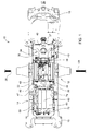
- Fig. 1
- is a top view of a front axle suspension for a work vehicle embodying the invention,
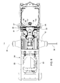
- Fig. 2
- is a top view of the front axle suspension of
Fig. 1 with a frame removed, - Fig. 3
- is a perspective view of a portion of the front axle suspension of
Fig. 1 , - Fig. 4
- is a schematic diagram of a hydraulic circuit which includes hydraulic components of
Fig. 1 , - Fig. 5
- is a bottom perspective view of the front axle suspension of
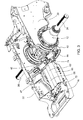
Fig. 1 , and - Fig. 6
- is a bottom partially sectioned view of the front axle suspension of
Fig. 1 . - Referring to
Figs. 1 ,2 and3 , afront axle suspension 10 for a work vehicle (not shown) couples anaxle housing 12 to avehicle frame 14. Thevehicle frame 14 includes afront frame member 16, arear frame member 18, aleft frame member 20 and aright frame member 22. The left andright frame members axle housing 12 supports aleft axle shaft 24 and aright axle shaft 26. - The
front axle suspension 10 includes aleft pivot rod 30 attached to theleft frame member 20, and aright pivot rod 32 attached to theright frame member 22. Thefront axle suspension 10 also includes asuspension arm 34 having afirst end 36 fixed to arear end 38 of theaxle housing 12 and having asecond end 40 pivotally coupled to the left andright pivot rods right pivot rods vehicle frame 14 and which is parallel to the axis of theaxle shafts separate pivot rods right frame members suspension arm 34 includes acentral opening 43 through which extends adrive shaft 37. - As best seen in
Fig. 6 ,left pivot rod 30 includes aflange 27 which is attached to an outer surface ofleft frame member 20, andleft pivot rod 30 extends through abore 31 formed by theleft frame member 20 as is rotatably received by abore 25 formed in thesuspension arm 34. Similarly,right pivot rod 32 includes aflange 29 which is attached to an outer surface ofright frame member 22, andright pivot rod 32 extends through abore 33 formed by theright frame member 22 as is rotatably received by abore 35 formed in thesuspension arm 34. - The
front axle suspension 10 also includes an attachingmember 42 which is fixed to the front end of theaxle housing 12. Thefront axle suspension 10 also includes variable length left and righthydraulic cylinders hydraulic cylinder 44 has an upper end pivotally coupled bybracket 45 to theleft frame member 20 and has a lower end pivotally coupled to a lower left part of the attachingmember 42. The righthydraulic cylinder 46 has an upper end pivotally coupled bybracket 47 to theright frame member 22 and has a lower end pivotally coupled to a lower right part of the attachingmember 42. - Referring now to
Fig. 4 , the left and righthydraulic cylinders valve control circuit 50. Hydraulicvalve control circuit 50 controls communication of hydraulic fluid from apump line 52, atank line 54, aload sense line 56 to the left andright cylinders rod accumulator 58 and a pair ofpiston accumulators hydraulic cylinder 44 includes apiston chamber 64 connected to apiston chamber 66 of righthydraulic cylinder 46, and lefthydraulic cylinder 44 includes arod chamber 68 connected to arod chamber 70 of righthydraulic cylinder 46. - As best seen in
Figs. 1 ,2 and3 , avalve housing 72 is mounted to asupport member 74. As best seen inFig. 5 , thesupport member 74 is attached to a bottom surface of left andright frame members valve housing 72 is spaced apart from and adjacent to thefront frame member 16 and forward of theaxle housing 12. One end of theaccumulators valve housing 72. The other end of theaccumulators support member 74. Theaccumulators valve housing 72 and the attachingmember 42. The components of the hydraulicvalve control circuit 50 may be enclosed within thevalve housing 72. Theaccumulators - The
accumulators front axle suspension 10. The hydraulicvalve control circuit 50 includes a valve which can limit movement by blocking flow between the left and righthydraulic cylinders accumulators valve control circuit 50 may also operate to level the suspension height by adding or subtracting oil from the left and righthydraulic cylinders - Thus, with this
front axle suspension 10, the left and righthydraulic cylinders valve control circuit 50 to attenuate power hop and provide better ride comfort on a 4WD articulated tractor. Thefront axle suspension 10 has a single degree of freedom and the movement of the front axle can be controlled by the left and righthydraulic cylinders
Claims (7)
- A front axle suspension for a work vehicle supporting an axle housing (12) with respect to a vehicle frame (14) having a fore-and-aft axis, the axle housing (12) supporting left and right axle shafts (24, 26) which extend perpendicularly with respect to the fore-and-aft axis, the front axle suspension (10) comprising a suspension arm (34) having a first end (36) fixed to a rear end (38) of the axle housing (12) and having a second end (40) pivotally coupled to the vehicle frame (14) about a pivot axis which is perpendicular with respect to the fore-and-aft axis; a variable length left hydraulic cylinder (44) having an upper end pivotally coupled to a left part (20) of the vehicle frame (14) and having a lower end pivotally coupled to the axle housing (12); and a variable length right hydraulic cylinder (46) having an upper end pivotally coupled to a right part (22) of the vehicle frame (14) and having a lower end pivotally coupled to the axle housing (12).
- The front axle suspension according to claim 1, characterized in that the left and right hydraulic cylinders (44, 46) are hydraulically connected in parallel.
- The front axle suspension according to claim 1 or 2, characterized in that the vehicle frame (14) comprises a front frame member (16), a rear frame member (18), a left frame member (20) and a right frame member (22), wherein a left pivot rod (30) is attached to the left frame member (20) and a right pivot rod (32) is attached to the right frame member (22), and wherein the second end (40) of the suspension arm (34) pivotally receives the left and right pivot rods (30, 32).
- The front axle suspension according to claims 1 to 3, characterized in that the suspension arm (34) is fixed to a rear end (38) of the axle housing (12), wherein the left hydraulic cylinder (44) is pivotally coupled to a left front portion of the axle housing (12) and the right hydraulic cylinder (46) is pivotally coupled to a right front portion of the axle housing (12).
- The front axle suspension according to claims 1 to 4, characterized in that a valve housing (72) is mounted to the vehicle frame (14), wherein hydraulic components are mounted to the valve housing (72) between the valve housing (72) and a front end of the axle housing (12).
- The front axle suspension according to claim 5, characterized in that the hydraulic components comprise a rod accumulator (58) and a pair of piston accumulators (60, 62).
- Work vehicle, in particular agricultural tractor, comprising a front axle suspension (10) according to claims 1 to 6.
Applications Claiming Priority (1)
| Application Number | Priority Date | Filing Date | Title |
|---|---|---|---|
| US14/459,938 US9428025B2 (en) | 2014-08-14 | 2014-08-14 | Axle suspension |
Publications (1)
| Publication Number | Publication Date |
|---|---|
| EP2985160A1 true EP2985160A1 (en) | 2016-02-17 |
Family
ID=53835329
Family Applications (1)
| Application Number | Title | Priority Date | Filing Date |
|---|---|---|---|
| EP15180604.9A Withdrawn EP2985160A1 (en) | 2014-08-14 | 2015-08-11 | Front axle suspension for a work vehicle |
Country Status (4)
| Country | Link |
|---|---|
| US (1) | US9428025B2 (en) |
| EP (1) | EP2985160A1 (en) |
| CN (1) | CN105365511B (en) |
| BR (1) | BR102015019299B1 (en) |
Families Citing this family (2)
| Publication number | Priority date | Publication date | Assignee | Title |
|---|---|---|---|---|
| DE102017205827A1 (en) * | 2017-04-05 | 2018-10-11 | Deere & Company | Method for providing a ballast proposal of an agricultural tractor |
| US11358430B2 (en) | 2020-06-16 | 2022-06-14 | Deere & Company | Suspension system with variable roll resistance |
Citations (3)
| Publication number | Priority date | Publication date | Assignee | Title |
|---|---|---|---|---|
| US3917295A (en) * | 1973-06-30 | 1975-11-04 | Nissan Motor | Fluid operated vehicle body level control system |
| EP1234696A1 (en) * | 2001-02-23 | 2002-08-28 | Dana Italia S.p.A | Damped suspended axle, in particular for agricultural machines, industrial vehicles and the like |
| FR2918928A1 (en) * | 2007-07-20 | 2009-01-23 | Kubota Kk | SUSPENSION STRUCTURE FOR A WORKING MACHINE |
Family Cites Families (26)
| Publication number | Priority date | Publication date | Assignee | Title |
|---|---|---|---|---|
| US3592485A (en) * | 1969-10-22 | 1971-07-13 | Ainsworth Ind Corp And Harold | Manually activated level control for automobiles |
| US3836161A (en) * | 1973-01-08 | 1974-09-17 | Midland Ross Corp | Leveling system for vehicles with optional manual or automatic control |
| US3953040A (en) * | 1975-03-05 | 1976-04-27 | Caterpillar Tractor Co. | Leveling and lockup system for wheel tractor suspension system |
| US3992035A (en) * | 1975-06-20 | 1976-11-16 | Caterpillar Tractor Co. | Combination hydraulic and mechanical suspension system |
| JPS55124315U (en) * | 1979-02-24 | 1980-09-03 | ||
| US4415179A (en) * | 1981-04-15 | 1983-11-15 | Marinelli Joseph A | Axle and air bag suspension |
| US4733876A (en) * | 1986-12-17 | 1988-03-29 | Heider Merle J | Suspension and leveling system for a vehicle |
| DE4115311C2 (en) * | 1991-05-10 | 1994-08-25 | Deere & Co | Spring-mounted suspension of a steering axle |
| EP0603394B1 (en) * | 1991-09-09 | 1997-04-23 | Hitachi Construction Machinery Co., Ltd. | Suspension system for work vehicle |
| US5639119A (en) * | 1992-12-04 | 1997-06-17 | Trak International, Inc. | Forklift stabilizing apparatus |
| US5458359A (en) * | 1994-08-08 | 1995-10-17 | Brandt; Larry A. | Missing link swivel for four-link rigid axle suspensions |
| DE19643263C2 (en) * | 1996-10-19 | 2002-06-20 | Deere & Co | Suspended, suspended axle suspension |
| DE19748224B4 (en) | 1997-10-31 | 2005-07-14 | Deere & Company, Moline | Hydropneumatic axle suspension for driven vehicle axles |
| DE19962406A1 (en) * | 1999-12-22 | 2001-07-19 | Zf Lemfoerder Metallwaren Ag | Axle suspension for rigid axles of vehicles |
| US6470991B1 (en) | 2000-09-14 | 2002-10-29 | Deere & Company | Tractor with front suspension |
| US6520277B1 (en) | 2000-09-14 | 2003-02-18 | Deere & Company | Tractor steering cylinder with internal adjustable steering stops |
| ES2215846T3 (en) * | 2001-01-26 | 2004-10-16 | Dana Italia S.P.A | SUSPENDED SHAFT OF THE ARTICULATED CONNECTION TYPE FOR INDUSTRIAL VEHICLES. |
| US20050269796A1 (en) * | 2004-06-03 | 2005-12-08 | Sawarynski Thomas J | Controlling power-hop in a vehicle |
| US7204340B2 (en) * | 2004-08-05 | 2007-04-17 | Cnh America Llc | Tractor rear suspension |
| US7516968B2 (en) * | 2005-04-29 | 2009-04-14 | Hendrickson Usa, L.L.C. | Wishbone-shaped linkage component and suspension systems incorporating the same |
| US7398984B2 (en) * | 2005-11-18 | 2008-07-15 | Detroit Speed & Engineering, Inc. | Vehicle suspension system incorporating swivel link assembly |
| WO2007149442A2 (en) * | 2006-06-16 | 2007-12-27 | Sanluis Rassini, S.A. De C.V. | Dual leaf suspension for vehicle drive arrangement |
| US7510198B2 (en) * | 2007-03-22 | 2009-03-31 | Cnh America Llc | Axle suspension system |
| WO2009139829A2 (en) * | 2008-05-02 | 2009-11-19 | Sanluis Rassini, S.A. De C.V. | Dual leaf vehicle suspension with j-shaped spring element |
| US8517394B2 (en) * | 2011-08-01 | 2013-08-27 | Cnh America Llc | Adjustable suspension system for a work vehicle |
| US8919789B2 (en) * | 2013-03-15 | 2014-12-30 | Agco Corporation | Harvester with suspended rear axle |
-
2014
- 2014-08-14 US US14/459,938 patent/US9428025B2/en active Active
-
2015
- 2015-08-11 EP EP15180604.9A patent/EP2985160A1/en not_active Withdrawn
- 2015-08-12 BR BR102015019299-1A patent/BR102015019299B1/en active IP Right Grant
- 2015-08-13 CN CN201510497128.8A patent/CN105365511B/en active Active
Patent Citations (3)
| Publication number | Priority date | Publication date | Assignee | Title |
|---|---|---|---|---|
| US3917295A (en) * | 1973-06-30 | 1975-11-04 | Nissan Motor | Fluid operated vehicle body level control system |
| EP1234696A1 (en) * | 2001-02-23 | 2002-08-28 | Dana Italia S.p.A | Damped suspended axle, in particular for agricultural machines, industrial vehicles and the like |
| FR2918928A1 (en) * | 2007-07-20 | 2009-01-23 | Kubota Kk | SUSPENSION STRUCTURE FOR A WORKING MACHINE |
Also Published As
| Publication number | Publication date |
|---|---|
| CN105365511A (en) | 2016-03-02 |
| BR102015019299B1 (en) | 2022-08-30 |
| US20160046168A1 (en) | 2016-02-18 |
| CN105365511B (en) | 2019-06-28 |
| US9428025B2 (en) | 2016-08-30 |
| BR102015019299A2 (en) | 2016-06-28 |
Similar Documents
| Publication | Publication Date | Title |
|---|---|---|
| EP2403331B1 (en) | Boom mounting assembly for an agricultural application machine | |
| US8297634B2 (en) | Suspension system for an agricultural vehicle | |
| US7744149B2 (en) | Cab suspension linkage system | |
| RU2549104C2 (en) | Working agricultural machine with replacement unit | |
| CN101519028B (en) | Systeme de suspension hydraulique | |
| US8925964B1 (en) | Ballast assembly | |
| US20190321845A1 (en) | Control system, spray bar, carrier and method of implementation | |
| US10350953B2 (en) | Vehicle with axle suspension | |
| EP3059104B1 (en) | A hydraulic cylinder arrangement, suspension arrangement as well as control arrangement for impact, noice and vibration absorbing suspension of an operator cab | |
| US6745849B2 (en) | Towed implement | |
| US9428025B2 (en) | Axle suspension | |
| EP2300303B1 (en) | Tractor cab suspensions | |
| US20210016306A1 (en) | Sprayer boom suspension assembly | |
| US4070035A (en) | Ride strut for vehicle suspension system | |
| US20200148285A1 (en) | Semi-active cab suspension for large agricultural vehicles | |
| RU2494907C2 (en) | Agricultural vehicle cab suspension | |
| EP2977242B1 (en) | Isodiametric tractor with minimum maintenance | |
| JP7130605B2 (en) | Elevating device for work vehicle and work machine | |
| AU2014202860B2 (en) | Rear suspension for swather tractor | |
| US6782680B2 (en) | Agricultural machine | |
| US12428080B2 (en) | Crawler drive for an agricultural work machine and agricultural work machine | |
| WO1982001518A1 (en) | Torsion bar axle suspension | |
| RU2618613C1 (en) | Additional support axle | |
| RU2566442C1 (en) | Deep tiller | |
| US9415651B2 (en) | Rear suspension for swather tractor |
Legal Events
| Date | Code | Title | Description |
|---|---|---|---|
| PUAI | Public reference made under article 153(3) epc to a published international application that has entered the european phase |
Free format text: ORIGINAL CODE: 0009012 |
|
| AK | Designated contracting states |
Kind code of ref document: A1 Designated state(s): AL AT BE BG CH CY CZ DE DK EE ES FI FR GB GR HR HU IE IS IT LI LT LU LV MC MK MT NL NO PL PT RO RS SE SI SK SM TR |
|
| AX | Request for extension of the european patent |
Extension state: BA ME |
|
| 17P | Request for examination filed |
Effective date: 20160817 |
|
| RBV | Designated contracting states (corrected) |
Designated state(s): AL AT BE BG CH CY CZ DE DK EE ES FI FR GB GR HR HU IE IS IT LI LT LU LV MC MK MT NL NO PL PT RO RS SE SI SK SM TR |
|
| STAA | Information on the status of an ep patent application or granted ep patent |
Free format text: STATUS: THE APPLICATION IS DEEMED TO BE WITHDRAWN |
|
| 18D | Application deemed to be withdrawn |
Effective date: 20160818 |