EP2985122A1 - Method and apparatus for saving energy and reducing cycle time by optimal ordering of the industrial robotic path - Google Patents
Method and apparatus for saving energy and reducing cycle time by optimal ordering of the industrial robotic path Download PDFInfo
- Publication number
- EP2985122A1 EP2985122A1 EP15176747.2A EP15176747A EP2985122A1 EP 2985122 A1 EP2985122 A1 EP 2985122A1 EP 15176747 A EP15176747 A EP 15176747A EP 2985122 A1 EP2985122 A1 EP 2985122A1
- Authority
- EP
- European Patent Office
- Prior art keywords
- rating
- task
- cycle time
- candidate
- energy consumption
- Prior art date
- Legal status (The legal status is an assumption and is not a legal conclusion. Google has not performed a legal analysis and makes no representation as to the accuracy of the status listed.)
- Withdrawn
Links
Images


Classifications
-
- B—PERFORMING OPERATIONS; TRANSPORTING
- B25—HAND TOOLS; PORTABLE POWER-DRIVEN TOOLS; MANIPULATORS
- B25J—MANIPULATORS; CHAMBERS PROVIDED WITH MANIPULATION DEVICES
- B25J9/00—Programme-controlled manipulators
- B25J9/16—Programme controls
- B25J9/1656—Programme controls characterised by programming, planning systems for manipulators
- B25J9/1664—Programme controls characterised by programming, planning systems for manipulators characterised by motion, path, trajectory planning
-
- B—PERFORMING OPERATIONS; TRANSPORTING
- B25—HAND TOOLS; PORTABLE POWER-DRIVEN TOOLS; MANIPULATORS
- B25J—MANIPULATORS; CHAMBERS PROVIDED WITH MANIPULATION DEVICES
- B25J9/00—Programme-controlled manipulators
- B25J9/16—Programme controls
- B25J9/1656—Programme controls characterised by programming, planning systems for manipulators
- B25J9/1661—Programme controls characterised by programming, planning systems for manipulators characterised by task planning, object-oriented languages
-
- G—PHYSICS
- G05—CONTROLLING; REGULATING
- G05B—CONTROL OR REGULATING SYSTEMS IN GENERAL; FUNCTIONAL ELEMENTS OF SUCH SYSTEMS; MONITORING OR TESTING ARRANGEMENTS FOR SUCH SYSTEMS OR ELEMENTS
- G05B2219/00—Program-control systems
- G05B2219/30—Nc systems
- G05B2219/39—Robotics, robotics to robotics hand
- G05B2219/39361—Minimize time-energy cost
-
- G—PHYSICS
- G05—CONTROLLING; REGULATING
- G05B—CONTROL OR REGULATING SYSTEMS IN GENERAL; FUNCTIONAL ELEMENTS OF SUCH SYSTEMS; MONITORING OR TESTING ARRANGEMENTS FOR SUCH SYSTEMS OR ELEMENTS
- G05B2219/00—Program-control systems
- G05B2219/30—Nc systems
- G05B2219/40—Robotics, robotics mapping to robotics vision
- G05B2219/40102—Tasks are classified in types of unit motions
-
- G—PHYSICS
- G05—CONTROLLING; REGULATING
- G05B—CONTROL OR REGULATING SYSTEMS IN GENERAL; FUNCTIONAL ELEMENTS OF SUCH SYSTEMS; MONITORING OR TESTING ARRANGEMENTS FOR SUCH SYSTEMS OR ELEMENTS
- G05B2219/00—Program-control systems
- G05B2219/30—Nc systems
- G05B2219/40—Robotics, robotics mapping to robotics vision
- G05B2219/40112—Using graph grammars and fuzzy logic
-
- G—PHYSICS
- G05—CONTROLLING; REGULATING
- G05B—CONTROL OR REGULATING SYSTEMS IN GENERAL; FUNCTIONAL ELEMENTS OF SUCH SYSTEMS; MONITORING OR TESTING ARRANGEMENTS FOR SUCH SYSTEMS OR ELEMENTS
- G05B2219/00—Program-control systems
- G05B2219/30—Nc systems
- G05B2219/40—Robotics, robotics mapping to robotics vision
- G05B2219/40446—Graph based
-
- G—PHYSICS
- G05—CONTROLLING; REGULATING
- G05B—CONTROL OR REGULATING SYSTEMS IN GENERAL; FUNCTIONAL ELEMENTS OF SUCH SYSTEMS; MONITORING OR TESTING ARRANGEMENTS FOR SUCH SYSTEMS OR ELEMENTS
- G05B2219/00—Program-control systems
- G05B2219/30—Nc systems
- G05B2219/40—Robotics, robotics mapping to robotics vision
- G05B2219/40463—Shortest distance in time, or metric, time optimal
-
- G—PHYSICS
- G05—CONTROLLING; REGULATING
- G05B—CONTROL OR REGULATING SYSTEMS IN GENERAL; FUNCTIONAL ELEMENTS OF SUCH SYSTEMS; MONITORING OR TESTING ARRANGEMENTS FOR SUCH SYSTEMS OR ELEMENTS
- G05B2219/00—Program-control systems
- G05B2219/30—Nc systems
- G05B2219/40—Robotics, robotics mapping to robotics vision
- G05B2219/40465—Criteria is lowest cost function, minimum work path
-
- G—PHYSICS
- G05—CONTROLLING; REGULATING
- G05B—CONTROL OR REGULATING SYSTEMS IN GENERAL; FUNCTIONAL ELEMENTS OF SUCH SYSTEMS; MONITORING OR TESTING ARRANGEMENTS FOR SUCH SYSTEMS OR ELEMENTS
- G05B2219/00—Program-control systems
- G05B2219/30—Nc systems
- G05B2219/40—Robotics, robotics mapping to robotics vision
- G05B2219/40518—Motion and task planning
-
- G—PHYSICS
- G05—CONTROLLING; REGULATING
- G05B—CONTROL OR REGULATING SYSTEMS IN GENERAL; FUNCTIONAL ELEMENTS OF SUCH SYSTEMS; MONITORING OR TESTING ARRANGEMENTS FOR SUCH SYSTEMS OR ELEMENTS
- G05B2219/00—Program-control systems
- G05B2219/30—Nc systems
- G05B2219/40—Robotics, robotics mapping to robotics vision
- G05B2219/40523—Path motion planning, path in space followed by tip of robot
-
- Y—GENERAL TAGGING OF NEW TECHNOLOGICAL DEVELOPMENTS; GENERAL TAGGING OF CROSS-SECTIONAL TECHNOLOGIES SPANNING OVER SEVERAL SECTIONS OF THE IPC; TECHNICAL SUBJECTS COVERED BY FORMER USPC CROSS-REFERENCE ART COLLECTIONS [XRACs] AND DIGESTS
- Y02—TECHNOLOGIES OR APPLICATIONS FOR MITIGATION OR ADAPTATION AGAINST CLIMATE CHANGE
- Y02P—CLIMATE CHANGE MITIGATION TECHNOLOGIES IN THE PRODUCTION OR PROCESSING OF GOODS
- Y02P80/00—Climate change mitigation technologies for sector-wide applications
- Y02P80/10—Efficient use of energy, e.g. using compressed air or pressurized fluid as energy carrier
Definitions
- the present disclosure is directed, in general, to automated industrial operations and robotics, and in particular to methods and systems for determining reduced energy consumption and cycle time by optimal ordering of the industrial robot path.
- PDM Product data management
- PLM product lifecycle management
- Various disclosed embodiments include a method for saving energy and reducing cycle time by using optimal ordering of the industrial robotic path.
- the method includes receiving inputs including one or more of robot information, position information, and a complex operation, generating a plurality of task groups of the complex operation, calculating a group edge rating for each of a plurality of robotic movement edges between each of the plurality of tasks groups, calculating a candidate rating for each of a plurality of candidate paths, wherein the candidate rating comprises a summation of the group edge ratings for a candidate path, determining an optimal path comprising the candidate path with an optimal rating, wherein the optimal rating is determined by the lowest candidate rating, and returning the optimal path.
- FIGURES 1 through 7 discussed below, and the various embodiments used to describe the principles of the present disclosure in this patent document are by way of illustration only and should not be construed in any way to limit the scope of the disclosure. Those skilled in the art will understand that the principles of the present disclosure may be implemented in any suitably arranged device. The numerous innovative teachings of the present application will be described with reference to exemplary non-limiting embodiments.
- Computer-aided robotics (CAR) tools are widely used for robotic arm path planning for spot welding.
- the planned path generally, contains no more than several dozens of locations spread in its target area, based on part to be welded.
- the robotic operation should complete all the welds by reaching each one of them from a specific direction in order to avoid the robotic arm or welder colliding with the products or fixture elements.
- the order of completing all the welds impacts the manufacturing process time and energy consumption. As the number of welds required by the robotic operation increases, the process of determining the most efficient order of welding becomes more tedious. The chosen path tends to become more arbitrary as the amount of welding location increases, which in turn raise the likelihood that the path chosen is not the most time or energy efficient. For example, when the process has twenty welding locations, 2,432,902,008,176,640,000 different permutations exist.
- Additional constraints can include whether the robot can reach all locations from a given robot position and whether any collisions occur with the robot and any objects within its environment.
- a limited cycle time for completing tasks is another constraint that relates to production costs.
- Robots can be heavy power consumers. Robots work repeatedly on one or more tasks for long hours and have complex powertrains that can include engines, transmissions, and so on. In a typical production line, there can be many robots, which further amplifies these issues.
- Embodiments according to the disclosure find the most efficient or optimal robot operation order based on given constraints and in terms of power consumption and cycle time.
- the energy to time correlation can include ratings and rankings of the results of simulations that generate power or energy consumption values and cycle time values.
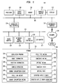
- FIG. 1 illustrates a block diagram of a data processing system in which an embodiment can be implemented, for example as a PDM system particularly configured by software or otherwise to perform the processes as described herein, and in particular as each one of a plurality of interconnected and communicating systems as described herein.
- the data processing system illustrated includes a processor 102 connected to a level two cache/bridge 104, which is connected in turn to a local system bus 106.
- Local system bus 106 may be, for example, a peripheral component interconnect (PCI) architecture bus.
- PCI peripheral component interconnect
- main memory 108 main memory
- graphics adapter 110 may be connected to display 111.
- Peripherals such as local area network (LAN) / Wide Area Network / Wireless (e.g. WiFi) adapter 112, may also be connected to local system bus 106.
- Expansion bus interface 114 connects local system bus 106 to input/output (I/O) bus 116.
- I/O bus 116 is connected to keyboard/mouse adapter 118, disk controller 120, and I/O adapter 122.
- Disk controller 120 can be connected to a storage 126, which can be any suitable machine usable or machine readable storage medium, including but not limited to nonvolatile, hard-coded type mediums such as read only memories (ROMs) or erasable, electrically programmable read only memories (EEPROMs), magnetic tape storage, and user-recordable type mediums such as floppy disks, hard disk drives and compact disk read only memories (CD-ROMs) or digital versatile disks (DVDs), and other known optical, electrical, or magnetic storage devices.
- ROMs read only memories
- EEPROMs electrically programmable read only memories
- CD-ROMs compact disk read only memories
- DVDs digital versatile disks
- the storage 126 stores the simulation program 152, the robot information 154, the position information 156, the complex operation 158, the energy consumption weight 160, the cycle time weight 162, the energy consumption rating 164, the cycle time rating 166, the candidate rating 168, the optimal rating 170, the candidate paths 172, the optimal path 174, the directed acyclic graphs (DAG) algorithm 176, and so on, which are described below.
- DAG directed acyclic graphs
- Audio adapter 124 Also connected to I/O bus 116 in the example shown is audio adapter 124, to which speakers (not shown) may be connected for playing sounds.
- Keyboard/mouse adapter 118 provides a connection for a pointing device (not shown), such as a mouse, trackball, trackpointer, touchscreen, etc.
- a data processing system in accordance with an embodiment of the present disclosure includes an operating system employing a graphical user interface.
- the operating system permits multiple display windows to be presented in the graphical user interface simultaneously, with each display window providing an interface to a different application or to a different instance of the same application.
- a cursor in the graphical user interface may be manipulated by a user through the pointing device. The position of the cursor may be changed and/or an event, such as clicking a mouse button, generated to actuate a desired response.
- One of various commercial operating systems such as a version of Microsoft WindowsTM, a product of Microsoft Corporation located in Redmond, Wash may be employed if suitably modified.
- the operating system is modified or created in accordance with the present disclosure as described.
- LAN/ WAN/Wireless adapter 112 can be connected to a network 130 (not a part of data processing system 100), which can be any public or private data processing system network or combination of networks, as known to those of skill in the art, including the Internet.
- Data processing system 100 can communicate over network 130 with server system 140, which is also not part of data processing system 100, but can be implemented, for example, as a separate data processing system 100.
- Figure 2 illustrates a complex operation path 240 for a simulated robot 210 in a three dimensional (3D) complex operation field of a robot simulation 200 in which an embodiment can be implemented.
- the simulated robot 210 represents a simulated model of the robot that allows for simulation of the movements of the robot.
- the simulated robot 210 is stored in the robot information 154 and is comprised of a base 215, a plurality of joints 220, and an end of arm (EOA) 225.
- the simulated robot 210 is fixed and positioned in the 3D complex operation field.
- the arm of the robot includes a plurality of joints 220 and connects the EOA 225 to the base 215.
- the simulated robot 210 moves and orients the EOA 225 by rotating at multiple joints 220.
- the simulated robot 210 rotates around three joints 220, but the simulated robot 210 can contain any amount of joints 220.
- the joints 220 used for the simulated robot 210 can any suitable type of joint 220, including but not limited to knuckle joints, turnbuckle joints, pin joints or ball joints.
- the EOA 225 is the end of the simulated robot 210 opposite of the base 215.
- the EOA 225 is an attachment or tooling required for the simulated robot 210 to complete the tasks of the complex operation 158, such as a welder, soldering iron, clamp, or any other suitable attachment or tooling.
- the EOA 225 includes a simulated robot contact point (SRCP) 230 and a simulated robot point frame (SRPF) 235.
- the SRCP 230 defines the point at the end of the EOA 225 which a task is performed.
- the SRPF 235 defines the orientation of the EOA 225 for the completion of tasks in the simulation.
- the complex operation 158 is comprised of a series of tasks in which the robot is used to complete.
- the complex operation 158 is represented by an initial location 245, a plurality of task locations 250, a final location 260, and a complex operation path 240 connecting all the locations.
- the task locations 250 representing the complex operation 158 are defined in the complex operation 158.
- the complex operation path 240 is defined by the order in which the tasks are to be performed.
- the complex operation path 240 begins at the initial location 245, continues to a plurality of task locations 250, and ends at the final location 260.
- the complex operation path 240 represents the optimal path 174 based on distance the EOA 225 follows as the simulated robot 210 moves from one task location 250 to the next. Because the joints 220 on the simulated robot 210 are different sizes and types, the path of the EOA 225 does not necessarily move along the illustrated path.
- the complex operation 158 requires the EOA 225 to move along the complex operation path 240 starting at the initial location 245 and ending at the final location 260.
- the initial location 245 and final location 260 are illustrated as different locations, but they could also be the same location.
- the initial location 245 and final location 260 might also be a task location 250 or could just be a location not interfering with the insertion or removal of the product.
- the complex operation 158 requires a plurality of task to be performed.
- Each task in the complex operation 158 is represented in the robot simulation 200 by a task location 250 and a tool center point frame TCPF 255.
- the plurality of task locations 250 defines the complex operation path 240 and the location in the 3D complex operation field of the task to be performed.
- the TCPF 255 defines the required orientation, with a tolerance, in which the EOA 225 must suitably match at a particular task location 250 to complete the task.
- the simulated robot 210 In order for an EOA 225 to complete a task for the simulation, the simulated robot 210 must extend the EOA 225 so that the SRCP 230 reaches the task location 250 and the SRPF 235 must match within the tolerance of the TCPF 255 for the task location 250.
- the simulation program 152 calculates the energy consumption 265 and cycle time 270 for robotic movement 275 of the simulated robot 210.
- the energy consumption 265 is the amount of energy consumed by the robot determined by the robotic simulation 200.
- the cycle time 270 is the amount of time the robot takes to complete a cycle determined by the robotic simulation 200. In this embodiment, the energy consumption 265 and cycle time 270 are determined between each task location 250.
- Figure 3 illustrates a plurality of task locations 250 grouped into a plurality of task groups 300 in accordance with the disclosed embodiments. Grouping the task locations 250 allows for a more efficient ordering of tasks greatly reducing the amount of permutations of candidate paths 172.
- the task locations are grouped by proximity, by definition created by a user, or any other suitable method of grouping task locations.
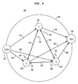
- Figure 4 illustrates a task group DAG 400 of a task group 300 comprising task edge ratings 420 for robotic movement edges 410 between task locations 250 in accordance with the disclosed embodiments.
- the task group 300 comprises a plurality of task locations 250, a plurality of robotic movement edges 410 connecting the plurality of task locations 250, a task edge rating 420 for each robotic movement edge 410, a task group entry location 430, a plurality of task group entry edges 450 connecting the task group entry location 430 to each of the task locations 250 in the task group 300, a task group exit location 440 and a plurality of task group exit edges 450 connecting each of the task location 250 in the task group 300 to the task group exit location 440.
- robotic movement edges 410 are generated connecting each task location 250 to all the other task locations 250.
- the robotic movement edges' 410 weight values connecting the different task locations 250 illustrate the rating of the simulated robot 210 to move between task locations 250. Because the robotic movement edges 410 are representing robotic movement 275, the task edge rating 420 is different for the robotic movement 275 in each direction due to forces such as gravity.
- the task group entry location 430 is the location where the task group DAG 400 begins for each task group 300.
- the task group entry location 430 and the task group exit location 440 are located on the outer fringe of the task group 300.
- the task group entry location 430 represents the location where the simulated robot 210 enters the task group 300.
- the task group exit location 440 represents the location where the simulated robot 210 exits the task group 300.
- a task group entry edge 450 connects the task group entry location 430 with each of the task locations 250 in the task group 300.
- the task group exit location 440 is the location where the task group DAG 400 ends for each task group 300.
- a task group exit edge 460 connects the task group exit location 440 with each of the task locations 250 in the task group 300.
- the task group entry location 430 and the task group exit location 440 are not actually real task locations 250, but dummy locations, so the task group DAG 400 will be closed and will able to be resolved by DAG algorithms 176. Since it is a dummy location, it has no robotic movement 275 and therefore the task group entry edges 450 and the task group exit edges 460 contain a '0' rating.
- the task group entry location 430 and the task group exit location 440 are dummy locations, the location on the fringe of the task group 300 is irrelevant, as long as the location is on the fringe.
- the simulation program 152 calculates energy consumption 265 and cycle time 270 for all the robotic movement edges 410 required for the robotic motion 275 between all task locations 250 of the complex operation 158.
- the cycle time 270 and the energy consumption 265 can be calculated from an realistic robot simulation (RRS) for all possible robotic movements 275 between task locations 250.
- the robot simulation 200 simulates the robot performing the complex operation 158 and the robot simulation 200 provides the cycle time 270 and the energy consumption 265 of the robotic movement edge 410.
- the system determines the energy consumption weight (EW) 160 and the cycle time weight (TW) 162.
- EW 160 and the TW 162 can be constant or based on a combination of values including the cycle time 270 and the energy consumption 265 via a formula.
- the EW 160 formula ( f EW ) defines the weight the energy consumption 265 has on the ratings
- the TW 162 formula ( f TW ) defines the weight the cycle time 270 has on the ratings.
- the system determines an energy consumption rating (ER) 164 and a cycle time rating (TR) 166 based on the EW 160, the TW 162, the cycle time 270, and the energy consumption 265.
- the system determines a comprehensive edge rating (r i ) based on one or more of the ER 164, the TR 166, the EW 160, the TW 162, the cycle time 270, and the energy consumption 265.
- the edge ratings inside the task groups 300 are designated as task edge ratings 420 and the edge ratings between the task groups 300 are designated as group edge ratings 520 (illustrated in Figure 5 ).
- the DAG algorithm 176 Based on the energy consumption 265 (W i ), the cycle time 270 (t i ), the ER 164, the TR 166, the r i , the DAG algorithm 176 provides the optimal path 174 having the lowest value of all the r i values.
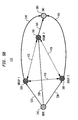
- Figures 5A and 5B illustrate DAGs of different group edge ratings 520 for robotic movement edges 410 between task groups 300 for completing a complex operation in accordance with the disclosed embodiments.
- Figure 5A illustrates an operation DAG 500 comprising an initial location 245, a plurality of initial edges 530 connecting the initial location 245 to each of the plurality of task groups 300, a final location 260, a plurality of final edges 540 connecting the plurality of task groups 300 to the final location 260, a plurality of robotic movements edges 410 connecting the plurality of task groups 300, and a plurality of task groups 300 each containing a plurality of task locations 250, a plurality of robotic movement edges 410 connecting the plurality of task locations 250, a task edge rating 420 for each robotic movement edge 410, an task group entry location 430 and a task group exit location 440. While Figure 5A illustrates all the task locations 250 inside task groups 300, a single task location 250 may be outside of all the task groups 300. In these situations, the single task location 250 is included in the operation DAG 500 and connected to the task groups 300 with robotic movement edges 410.
- robotic movement edges 410 are generated connecting each task group 300 to all the other task groups 300.
- the robotic movement edges' 410 weight values connecting the task groups 300 illustrate the rating of the simulated robot 210 to move between task groups 300. Because the robotic movement edges 410 are representing robotic movement 275, the group edge rating 520 is different for the robotic movement 275 in each direction due to forces such as gravity.
- the initial location 245 is the location where the operation DAG 500 begins.
- a plurality of initial edges 530 connects the initial location 245 with each of the task group 300.
- the final location 260 is the location where the operation DAG 500 ends.
- a plurality of final edges 540 connects the final location 260 with each of the task group 300.
- the initial location 245 and the final location 260 are not actually real task locations 250, but dummy locations, so the operation DAG 500 will be closed and will able to be resolved by DAG algorithms 176. Since it is a dummy location, it has no robotic movement 275 and therefore the initial edges 530 and the final edges 540 contain a '0' rating.
- Figure 5B illustrates a simplified DAG 510 comprising a plurality of task groups 300, an initial location 245, a plurality of initial edges 530 connecting the initial location to each of the plurality of task groups 300, a final location 260, a plurality of final edges 540 connecting the plurality of task groups 300 to the final location 260, and a plurality of robotic movements edges 410 connecting the plurality of task groups 300.
- the differences in the summation of task edge ratings 420 for the different candidate paths 172 inside a task group 300 are negligent in comparison with the differences in summation of group edge ratings 520 for the different candidate paths 172 that a simplified DAG 510 is used for determining the optimal path 174.
- the simplified DAG 510 determines the optimal path is used to reduce the processing time to solve the DAG algorithm 176, decrease the complexity of the model, or any other suitable reason.
- Figures 6A-6C illustrate different alternatives when a collision event for a robotic movement 275 is discovered in accordance with the disclosed embodiments. While the different alternatives are illustrated for robotic movements 275 between task locations 250 inside a task group 300, the alternatives are also implemented on the robotic movements 275 between task groups 300 when collisions events are detected.
- FIG. 6A illustrates the use of a flyby path 600 to remove the collision event from the robotic movement 275.
- the robotic movement 275 can be altered by adding one or more flyby locations 630 or additional non-task locations.
- Flyby locations 630 are described, for example, in U.S. Patent Publication 2011/0153080 A1 , which is hereby incorporated by reference.
- the candidate path 172 is changed (a new fly-by location 630 is added) and the weights of robotic movement edges 410 for this specific candidate path 172 should be recalculated. Note that adding a flyby location 630 for a candidate path 172, where a collision is detected, does not necessarily add that flyby location 630 to other candidate paths 172, whether or not a collision is detected.
- Candidate paths 172 could contain unique flyby locations 630 between task locations 250 when a collision is detected. Different flyby locations 630 can be added for different candidate paths 172 between similar consecutive task locations 250. The robotic movement edges 410 where the collision is detected will be split connecting the previously connect task locations 250 to the flyby location 630.
- Figure 6B illustrates the use of an alternative path 610 to remove the collision event from the robotic movement 275.
- the system removes the collision event by altering the robotic movement 275 between the consecutive task locations 250 when a collision event is detected.
- Figure 6C illustrates the use of a removed path 620 to remove the collision event from the robotic movement 275.
- the collision event is removed by the system by removing the robotic movement edges 410 which contain the collision event.
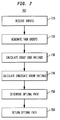
- FIG. 7 illustrates a flowchart 700 of a process for saving energy and reducing cycle time by using optimal ordering of the industrial robotic path in accordance with disclosed embodiments that may be performed, for example, by a PLM or PDM system.
- the energy consumption 265 of the robot is realistic and accurate based on a RRS performed by a data processing system 100, such as the data processing system 100 of Figure 1 .
- the RRS interface is known to those of skill in the art, and is described at time of filing, for example, at realistic-robot-simulation.org.
- the system uses RRS simulation to accumulate the energy consumption 265 for each one of the candidate paths 172 and to find the collisions within the robot simulation 200.
- the system receives inputs including one or more of robot information 154, and position information 156, and the complex operation 158.
- the robot information 154 can include a model of the robot that allows for simulation of the movements of the robot.
- the robot information 154 also can include information related to the geometry or environment of the robot, the robot's surroundings, and any objects pertinent to the placement or location of the robot.
- the complex operation 158 can include information on the complex operation 158 that the robot is to perform, the initial position, a set of task locations 250 for the robot to reach to perform the complex operation 158, TCPF 255, and any other operation related information.
- the position information 156 contains the robot's position.
- One or more of the processor 102, the memory 108, and the simulation program 152 running on the processor 102 receive the inputs via one or more of the local system bus 106, the adapter 112, the network 130, the server 140, the interface 114, the I/O bus 116, the disk controller 120, the storage 126, and so on.
- Receiving can include retrieving from storage 126, receiving from another device or process, receiving via an interaction with a user, or otherwise.
- the system generates a plurality of task groups 300 for a complex operation 158 based on the inputs.
- the system generates a plurality of task locations 250 in each of the plurality of task groups 300.
- the TCPF 255 information including desired task orientation, the task orientation tolerance, and any other information required for reaching the task location 250, is added to the 3D complex operation field.
- the system generates a task location 250 in the 3D complex operation field for each of the one or more tasks required for completion of the complex operation 158. Because the task group 300 is not a task location 250, only the SRCP 230 needs to locate the task group 300.
- the system While running the simulation for each candidate path 172, the system also determines if the simulation includes a collision and adjusts the candidate path 172 to remove one or more collision events. If the system cannot adjust the robotic movement 275 to remove the one or more collision events, the system removes the robotic movement edge 410 from the DAG that contain collision events between consecutive task locations 250. If a collision event is detected at a task location 250, then the system removes the candidate paths 172 that contain the task locations 250 determined to contain a collision event. In certain embodiments, the collision is removed by the system altering the robotic movement 275 between the consecutive task locations 250 when a collision event is detected. The robotic movement 275 can be altered by adding one or more flyby locations 630 or additional non-task locations, changing the TCPF 255 of the task location 250, changing the configuration of the robot, and so on.
- the candidate path 172 is changed (a new fly-by location 630 is added) and the weights of edges for this specific candidate path 172 should be recalculated.
- adding a flyby location 630 for a candidate path 172, where a collision is detected does not necessarily add that flyby location 630 to other candidate paths 172, whether or not a collision is detected.
- Candidate paths 172 could contain unique flyby locations 630 between task locations 250 when a collision is detected. Different flyby locations 630 can be added for different candidate paths 172 between similar consecutive task locations 250.
- the system calculates the group edge ratings 520 for each of a plurality of robotic movement edges 410 between each of the plurality of task groups 300. Where a robotic movement edge 410 accounts for the robotic movement 275 between consecutive task groups 300. In some embodiments, the system calculates a task edge rating 420 for each of the plurality of robotic movement edges 410 between each task location 250 inside each of the plurality of task groups 300. Where a robotic movement edge 410 also accounts for the robotic movement 275 between consecutive task locations 250.
- the system calculates the energy consumption 265 and the cycle time 270 for the robotic movements 275 for each of the candidate paths 172.
- the energy consumption calculation includes the energy the robot consumes to move to the task locations 250 for the complex operation 158.
- the energy consumption 265 calculates the amount of energy consumed by the robot in order to complete the complex operation 158 for which the simulation was run.
- the robot simulation 200 can include pauses at task location 250 to incorporate energy calculations for a task to be completed, such as welding.
- the system removes the candidate path 172 for each candidate path 172 remaining, when the energy consumption 265 does not meet a threshold.
- the cycle time 270 is calculated as the time it takes to complete the robotic movement 275 and when the cycle time 270 does not meet the threshold, the system removes the candidate paths 172 which contain the robotic movement 275.
- step 740 the system calculates a candidate rating 168 for each of a plurality of candidate paths 172.
- a candidate rating 168 comprises a summation of group edge ratings 520 of robotic movements 275 for a candidate path 172.
- the candidate rating 168 further comprises a summation of the task edge ratings 420 for the candidate path 172.
- step 750 the system determines the optimal path 174 based on the candidate path 172 with an optimal rating 170. Where the optimal rating 170 is determined based on the lowest candidate rating 168.
- step 760 the system returns the optimal path 174 based on the candidate path 172 with an optimal rating 170 between the energy consumption 265 and the cycle time 270.
- the optimal rating 170 is determined as a correlation between the energy consumption 265 and the cycle time 270 and is determined based on the lowest weight of the candidate paths 172.
- machine usable/readable or computer usable/readable mediums include: nonvolatile, hard-coded type mediums such as read only memories (ROMs) or erasable, electrically programmable read only memories (EEPROMs), and user-recordable type mediums such as floppy disks, hard disk drives and compact disk read only memories (CD-ROMs) or digital versatile disks (DVDs).
- ROMs read only memories
- EEPROMs electrically programmable read only memories
- user-recordable type mediums such as floppy disks, hard disk drives and compact disk read only memories (CD-ROMs) or digital versatile disks (DVDs).
Abstract
Description
- The present disclosure is directed, in general, to automated industrial operations and robotics, and in particular to methods and systems for determining reduced energy consumption and cycle time by optimal ordering of the industrial robot path.
- Product data management (PDM) systems manage product lifecycle management (PLM) systems and other data. Improved systems are desirable.
- Various disclosed embodiments include a method for saving energy and reducing cycle time by using optimal ordering of the industrial robotic path. The method includes receiving inputs including one or more of robot information, position information, and a complex operation, generating a plurality of task groups of the complex operation, calculating a group edge rating for each of a plurality of robotic movement edges between each of the plurality of tasks groups, calculating a candidate rating for each of a plurality of candidate paths, wherein the candidate rating comprises a summation of the group edge ratings for a candidate path, determining an optimal path comprising the candidate path with an optimal rating, wherein the optimal rating is determined by the lowest candidate rating, and returning the optimal path.
- The foregoing has outlined rather broadly the features and technical advantages of the present disclosure so that those skilled in the art may better understand the detailed description that follows. Additional features and advantages of the disclosure will be described hereinafter that form the subject of the claims. Those skilled in the art will appreciate that they may readily use the conception and the specific embodiment disclosed as a basis for modifying or designing other structures for carrying out the same purposes of the present disclosure. Those skilled in the art will also realize that such equivalent constructions do not depart from the spirit and scope of the disclosure in its broadest form.
- Before undertaking the DETAILED DESCRIPTION below, it may be advantageous to set forth definitions of certain words or phrases used throughout this patent document: the terms "include" and "comprise," as well as derivatives thereof, mean inclusion without limitation; the term "or" is inclusive, meaning and/or; the phrases "associated with" and "associated therewith," as well as derivatives thereof, may mean to include, be included within, interconnect with, contain, be contained within, connect to or with, couple to or with, be communicable with, cooperate with, interleave, juxtapose, be proximate to, be bound to or with, have, have a property of, or the like; and the term "controller" means any device, system or part thereof that controls at least one operation, whether such a device is implemented in hardware, firmware, software or some combination of at least two of the same. It should be noted that the functionality associated with any particular controller may be centralized or distributed, whether locally or remotely. Definitions for certain words and phrases are provided throughout this patent document, and those of ordinary skill in the art will understand that such definitions apply in many, if not most, instances to prior as well as future uses of such defined words and phrases. While some terms may include a wide variety of embodiments, the appended claims may expressly limit these terms to specific embodiments.
- For a more complete understanding of the present disclosure, and the advantages thereof, reference is now made to the following descriptions taken in conjunction with the accompanying drawings, wherein like numbers designate like objects, and in which:
-
Figure 1 illustrates a block diagram of a data processing system in which an embodiment can be implemented; -
Figure 2 illustrates a complex operation path for a simulated robot in a three dimensional (3D) complex operation field of a robot simulation in which an embodiment can be implemented; -
Figure 3 illustrates a plurality of task locations grouped into a plurality of task groups in accordance with the disclosed embodiments; -
Figure 4 illustrates a directed acyclic graph (DAG) of a task group comprising task edge ratings for robotic movement edges between task locations in accordance with the disclosed embodiments; -
Figures 5A and5B illustrate DAGs of different group edge ratings for robotic movement edges between task groups for completing a complex operation in accordance with the disclosed embodiments; -
Figures 6A-6C illustrate different alternatives when a collision event for a robotic movement is discovered in accordance with the disclosed embodiments; and -
Figure 7 illustrates flowchart of a process for saving energy and reducing cycle time by using optimal ordering of the industrial robotic path in accordance with disclosed embodiments. -
FIGURES 1 through 7 , discussed below, and the various embodiments used to describe the principles of the present disclosure in this patent document are by way of illustration only and should not be construed in any way to limit the scope of the disclosure. Those skilled in the art will understand that the principles of the present disclosure may be implemented in any suitably arranged device. The numerous innovative teachings of the present application will be described with reference to exemplary non-limiting embodiments. - Computer-aided robotics (CAR) tools are widely used for robotic arm path planning for spot welding. The planned path, generally, contains no more than several dozens of locations spread in its target area, based on part to be welded. The robotic operation should complete all the welds by reaching each one of them from a specific direction in order to avoid the robotic arm or welder colliding with the products or fixture elements.
- The order of completing all the welds impacts the manufacturing process time and energy consumption. As the number of welds required by the robotic operation increases, the process of determining the most efficient order of welding becomes more tedious. The chosen path tends to become more arbitrary as the amount of welding location increases, which in turn raise the likelihood that the path chosen is not the most time or energy efficient. For example, when the process has twenty welding locations, 2,432,902,008,176,640,000 different permutations exist.
- Consideration of numerous additional constraints makes finding the optimal operation path a complex task. Additional constraints can include whether the robot can reach all locations from a given robot position and whether any collisions occur with the robot and any objects within its environment. A limited cycle time for completing tasks is another constraint that relates to production costs.
- Robots can be heavy power consumers. Robots work repeatedly on one or more tasks for long hours and have complex powertrains that can include engines, transmissions, and so on. In a typical production line, there can be many robots, which further amplifies these issues.
- Embodiments according to the disclosure find the most efficient or optimal robot operation order based on given constraints and in terms of power consumption and cycle time. The energy to time correlation can include ratings and rankings of the results of simulations that generate power or energy consumption values and cycle time values.
- Applying this approach on every robot in a production line reduces the energy consumption and task cycle time resulting in reduced production costs. The reduced production costs come from finding optimal operation order for each robot in the production line to reduce overall energy consumption and cycle time.
-
Figure 1 illustrates a block diagram of a data processing system in which an embodiment can be implemented, for example as a PDM system particularly configured by software or otherwise to perform the processes as described herein, and in particular as each one of a plurality of interconnected and communicating systems as described herein. The data processing system illustrated includes aprocessor 102 connected to a level two cache/bridge 104, which is connected in turn to alocal system bus 106.Local system bus 106 may be, for example, a peripheral component interconnect (PCI) architecture bus. Also connected to local system bus in the illustrated example are amain memory 108 and agraphics adapter 110. Thegraphics adapter 110 may be connected to display 111. - Other peripherals, such as local area network (LAN) / Wide Area Network / Wireless (e.g. WiFi)
adapter 112, may also be connected tolocal system bus 106.Expansion bus interface 114 connectslocal system bus 106 to input/output (I/O)bus 116. I/O bus 116 is connected to keyboard/mouse adapter 118,disk controller 120, and I/O adapter 122.Disk controller 120 can be connected to astorage 126, which can be any suitable machine usable or machine readable storage medium, including but not limited to nonvolatile, hard-coded type mediums such as read only memories (ROMs) or erasable, electrically programmable read only memories (EEPROMs), magnetic tape storage, and user-recordable type mediums such as floppy disks, hard disk drives and compact disk read only memories (CD-ROMs) or digital versatile disks (DVDs), and other known optical, electrical, or magnetic storage devices. Thestorage 126 stores thesimulation program 152, therobot information 154, theposition information 156, thecomplex operation 158, theenergy consumption weight 160, thecycle time weight 162, theenergy consumption rating 164, thecycle time rating 166, thecandidate rating 168, theoptimal rating 170, thecandidate paths 172, theoptimal path 174, the directed acyclic graphs (DAG)algorithm 176, and so on, which are described below. - Also connected to I/
O bus 116 in the example shown isaudio adapter 124, to which speakers (not shown) may be connected for playing sounds. Keyboard/mouse adapter 118 provides a connection for a pointing device (not shown), such as a mouse, trackball, trackpointer, touchscreen, etc. - Those of ordinary skill in the art will appreciate that the hardware illustrated in
Figure 1 may vary for particular implementations. For example, other peripheral devices, such as an optical disk drive and the like, also may be used in addition or in place of the hardware illustrated. The illustrated example is provided for the purpose of explanation only and is not meant to imply architectural limitations with respect to the present disclosure. - A data processing system in accordance with an embodiment of the present disclosure includes an operating system employing a graphical user interface. The operating system permits multiple display windows to be presented in the graphical user interface simultaneously, with each display window providing an interface to a different application or to a different instance of the same application. A cursor in the graphical user interface may be manipulated by a user through the pointing device. The position of the cursor may be changed and/or an event, such as clicking a mouse button, generated to actuate a desired response.
- One of various commercial operating systems, such as a version of Microsoft Windows™, a product of Microsoft Corporation located in Redmond, Wash may be employed if suitably modified. The operating system is modified or created in accordance with the present disclosure as described.
- LAN/ WAN/
Wireless adapter 112 can be connected to a network 130 (not a part of data processing system 100), which can be any public or private data processing system network or combination of networks, as known to those of skill in the art, including the Internet.Data processing system 100 can communicate overnetwork 130 withserver system 140, which is also not part ofdata processing system 100, but can be implemented, for example, as a separatedata processing system 100. -
Figure 2 illustrates acomplex operation path 240 for asimulated robot 210 in a three dimensional (3D) complex operation field of arobot simulation 200 in which an embodiment can be implemented. - The
simulated robot 210 represents a simulated model of the robot that allows for simulation of the movements of the robot. Thesimulated robot 210 is stored in therobot information 154 and is comprised of abase 215, a plurality ofjoints 220, and an end of arm (EOA) 225. Thesimulated robot 210 is fixed and positioned in the 3D complex operation field. - The arm of the robot includes a plurality of
joints 220 and connects theEOA 225 to thebase 215. Thesimulated robot 210 moves and orients theEOA 225 by rotating atmultiple joints 220. In this embodiment, thesimulated robot 210 rotates around threejoints 220, but thesimulated robot 210 can contain any amount ofjoints 220. Thejoints 220 used for thesimulated robot 210 can any suitable type ofjoint 220, including but not limited to knuckle joints, turnbuckle joints, pin joints or ball joints. - The
EOA 225 is the end of thesimulated robot 210 opposite of thebase 215. TheEOA 225 is an attachment or tooling required for thesimulated robot 210 to complete the tasks of thecomplex operation 158, such as a welder, soldering iron, clamp, or any other suitable attachment or tooling. TheEOA 225 includes a simulated robot contact point (SRCP) 230 and a simulated robot point frame (SRPF) 235. TheSRCP 230 defines the point at the end of theEOA 225 which a task is performed. TheSRPF 235 defines the orientation of theEOA 225 for the completion of tasks in the simulation. - The
complex operation 158 is comprised of a series of tasks in which the robot is used to complete. In therobot simulation 200, thecomplex operation 158 is represented by aninitial location 245, a plurality oftask locations 250, afinal location 260, and acomplex operation path 240 connecting all the locations. Thetask locations 250 representing thecomplex operation 158 are defined in thecomplex operation 158. - The
complex operation path 240 is defined by the order in which the tasks are to be performed. Thecomplex operation path 240 begins at theinitial location 245, continues to a plurality oftask locations 250, and ends at thefinal location 260. Thecomplex operation path 240 represents theoptimal path 174 based on distance theEOA 225 follows as thesimulated robot 210 moves from onetask location 250 to the next. Because thejoints 220 on thesimulated robot 210 are different sizes and types, the path of theEOA 225 does not necessarily move along the illustrated path. - In certain embodiments, the
complex operation 158 requires theEOA 225 to move along thecomplex operation path 240 starting at theinitial location 245 and ending at thefinal location 260. Theinitial location 245 andfinal location 260 are illustrated as different locations, but they could also be the same location. Theinitial location 245 andfinal location 260 might also be atask location 250 or could just be a location not interfering with the insertion or removal of the product. - The
complex operation 158 requires a plurality of task to be performed. Each task in thecomplex operation 158 is represented in therobot simulation 200 by atask location 250 and a tool centerpoint frame TCPF 255. The plurality oftask locations 250 defines thecomplex operation path 240 and the location in the 3D complex operation field of the task to be performed. TheTCPF 255 defines the required orientation, with a tolerance, in which theEOA 225 must suitably match at aparticular task location 250 to complete the task. In order for anEOA 225 to complete a task for the simulation, thesimulated robot 210 must extend theEOA 225 so that theSRCP 230 reaches thetask location 250 and theSRPF 235 must match within the tolerance of theTCPF 255 for thetask location 250. - The
simulation program 152 calculates theenergy consumption 265 andcycle time 270 forrobotic movement 275 of thesimulated robot 210. Theenergy consumption 265 is the amount of energy consumed by the robot determined by therobotic simulation 200. Thecycle time 270 is the amount of time the robot takes to complete a cycle determined by therobotic simulation 200. In this embodiment, theenergy consumption 265 andcycle time 270 are determined between eachtask location 250. -
Figure 3 illustrates a plurality oftask locations 250 grouped into a plurality oftask groups 300 in accordance with the disclosed embodiments. Grouping thetask locations 250 allows for a more efficient ordering of tasks greatly reducing the amount of permutations ofcandidate paths 172. The task locations are grouped by proximity, by definition created by a user, or any other suitable method of grouping task locations. -
Figure 4 illustrates atask group DAG 400 of atask group 300 comprisingtask edge ratings 420 for robotic movement edges 410 betweentask locations 250 in accordance with the disclosed embodiments. Thetask group 300 comprises a plurality oftask locations 250, a plurality of robotic movement edges 410 connecting the plurality oftask locations 250, atask edge rating 420 for eachrobotic movement edge 410, a taskgroup entry location 430, a plurality of task group entry edges 450 connecting the taskgroup entry location 430 to each of thetask locations 250 in thetask group 300, a taskgroup exit location 440 and a plurality of task group exit edges 450 connecting each of thetask location 250 in thetask group 300 to the taskgroup exit location 440. - Between every
task location 250 inside thetask group 300, all possible robotic movement edges 410 are generated connecting eachtask location 250 to all theother task locations 250. The robotic movement edges' 410 weight values connecting thedifferent task locations 250 illustrate the rating of thesimulated robot 210 to move betweentask locations 250. Because the robotic movement edges 410 are representingrobotic movement 275, thetask edge rating 420 is different for therobotic movement 275 in each direction due to forces such as gravity. - The task
group entry location 430 is the location where thetask group DAG 400 begins for eachtask group 300. The taskgroup entry location 430 and the taskgroup exit location 440 are located on the outer fringe of thetask group 300. The taskgroup entry location 430 represents the location where thesimulated robot 210 enters thetask group 300. The taskgroup exit location 440 represents the location where thesimulated robot 210 exits thetask group 300. A taskgroup entry edge 450 connects the taskgroup entry location 430 with each of thetask locations 250 in thetask group 300. The taskgroup exit location 440 is the location where thetask group DAG 400 ends for eachtask group 300. A taskgroup exit edge 460 connects the taskgroup exit location 440 with each of thetask locations 250 in thetask group 300. - In this embodiment, the task
group entry location 430 and the taskgroup exit location 440 are not actuallyreal task locations 250, but dummy locations, so thetask group DAG 400 will be closed and will able to be resolved byDAG algorithms 176. Since it is a dummy location, it has norobotic movement 275 and therefore the task group entry edges 450 and the task group exit edges 460 contain a '0' rating. When the taskgroup entry location 430 and the taskgroup exit location 440 are dummy locations, the location on the fringe of thetask group 300 is irrelevant, as long as the location is on the fringe. - With all the
task locations 250 designated, thesimulation program 152 calculatesenergy consumption 265 andcycle time 270 for all the robotic movement edges 410 required for therobotic motion 275 between alltask locations 250 of thecomplex operation 158. - The
cycle time 270 and theenergy consumption 265 can be calculated from an realistic robot simulation (RRS) for all possiblerobotic movements 275 betweentask locations 250. Therobot simulation 200 simulates the robot performing thecomplex operation 158 and therobot simulation 200 provides thecycle time 270 and theenergy consumption 265 of therobotic movement edge 410. - The system determines the energy consumption weight (EW) 160 and the cycle time weight (TW) 162. Each of the
EW 160 and theTW 162 can be constant or based on a combination of values including thecycle time 270 and theenergy consumption 265 via a formula. In this embodiment, theEW 160 formula (fEW ) defines the weight theenergy consumption 265 has on the ratings and theTW 162 formula (fTW ) defines the weight thecycle time 270 has on the ratings. - The system determines an energy consumption rating (ER) 164 and a cycle time rating (TR) 166 based on the
EW 160, theTW 162, thecycle time 270, and theenergy consumption 265. In certain embodiments, theER 164 and theTR 166 can be determined via equations (1) and (2), respectively:

- The system determines a comprehensive edge rating (ri) based on one or more of the
ER 164, theTR 166, theEW 160, theTW 162, thecycle time 270, and theenergy consumption 265. In certain embodiments, thetask edge ratings 420 and the group edge ratings 520 (ri) are determined via equation (3):
where ri is the normalized edge rating of the robotic movement edge 410 (i), Wi is theenergy consumption 265 for the robotic movement edge 410 (i), and ti iscycle time 270 for the robotic movement edge 410 (i). In this embodiment, the edge ratings inside thetask groups 300 are designated astask edge ratings 420 and the edge ratings between thetask groups 300 are designated as group edge ratings 520 (illustrated inFigure 5 ).
where (n) is the number of robotic movement edges 410 and:
so that the sum of all normalized rankings (ri) is equal to 1 and the normalized ranking of eachrobotic movement edge 410 is based on the summation of the edge ratings for all the robotic movement edges 410. - Based on the energy consumption 265 (Wi), the cycle time 270 (ti), the
ER 164, theTR 166, the ri, theDAG algorithm 176 provides theoptimal path 174 having the lowest value of all the ri values. -
Figures 5A and5B illustrate DAGs of differentgroup edge ratings 520 for robotic movement edges 410 betweentask groups 300 for completing a complex operation in accordance with the disclosed embodiments. -
Figure 5A illustrates anoperation DAG 500 comprising aninitial location 245, a plurality ofinitial edges 530 connecting theinitial location 245 to each of the plurality oftask groups 300, afinal location 260, a plurality offinal edges 540 connecting the plurality oftask groups 300 to thefinal location 260, a plurality of robotic movements edges 410 connecting the plurality oftask groups 300, and a plurality oftask groups 300 each containing a plurality oftask locations 250, a plurality of robotic movement edges 410 connecting the plurality oftask locations 250, atask edge rating 420 for eachrobotic movement edge 410, an taskgroup entry location 430 and a taskgroup exit location 440. WhileFigure 5A illustrates all thetask locations 250 insidetask groups 300, asingle task location 250 may be outside of all thetask groups 300. In these situations, thesingle task location 250 is included in theoperation DAG 500 and connected to thetask groups 300 with robotic movement edges 410. - Between every
task group 300, all possible robotic movement edges 410 are generated connecting eachtask group 300 to all theother task groups 300. The robotic movement edges' 410 weight values connecting thetask groups 300 illustrate the rating of thesimulated robot 210 to move betweentask groups 300. Because the robotic movement edges 410 are representingrobotic movement 275, thegroup edge rating 520 is different for therobotic movement 275 in each direction due to forces such as gravity. - The
initial location 245 is the location where theoperation DAG 500 begins. A plurality ofinitial edges 530 connects theinitial location 245 with each of thetask group 300. Thefinal location 260 is the location where theoperation DAG 500 ends. A plurality offinal edges 540 connects thefinal location 260 with each of thetask group 300. - In this embodiment, the
initial location 245 and thefinal location 260 are not actuallyreal task locations 250, but dummy locations, so theoperation DAG 500 will be closed and will able to be resolved byDAG algorithms 176. Since it is a dummy location, it has norobotic movement 275 and therefore theinitial edges 530 and thefinal edges 540 contain a '0' rating. -
Figure 5B illustrates asimplified DAG 510 comprising a plurality oftask groups 300, aninitial location 245, a plurality ofinitial edges 530 connecting the initial location to each of the plurality oftask groups 300, afinal location 260, a plurality offinal edges 540 connecting the plurality oftask groups 300 to thefinal location 260, and a plurality of robotic movements edges 410 connecting the plurality oftask groups 300. - In certain embodiments, the differences in the summation of
task edge ratings 420 for thedifferent candidate paths 172 inside atask group 300 are negligent in comparison with the differences in summation ofgroup edge ratings 520 for thedifferent candidate paths 172 that asimplified DAG 510 is used for determining theoptimal path 174. In other embodiments, thesimplified DAG 510 determines the optimal path is used to reduce the processing time to solve theDAG algorithm 176, decrease the complexity of the model, or any other suitable reason. -
Figures 6A-6C illustrate different alternatives when a collision event for arobotic movement 275 is discovered in accordance with the disclosed embodiments. While the different alternatives are illustrated forrobotic movements 275 betweentask locations 250 inside atask group 300, the alternatives are also implemented on therobotic movements 275 betweentask groups 300 when collisions events are detected. -
Figure 6A illustrates the use of aflyby path 600 to remove the collision event from therobotic movement 275. Therobotic movement 275 can be altered by adding one ormore flyby locations 630 or additional non-task locations.Flyby locations 630 are described, for example, inU.S. Patent Publication 2011/0153080 A1 , which is hereby incorporated by reference. When adding flybylocations 630, thecandidate path 172 is changed (a new fly-bylocation 630 is added) and the weights of robotic movement edges 410 for thisspecific candidate path 172 should be recalculated. Note that adding aflyby location 630 for acandidate path 172, where a collision is detected, does not necessarily add thatflyby location 630 toother candidate paths 172, whether or not a collision is detected.Candidate paths 172 could containunique flyby locations 630 betweentask locations 250 when a collision is detected.Different flyby locations 630 can be added fordifferent candidate paths 172 between similarconsecutive task locations 250. The robotic movement edges 410 where the collision is detected will be split connecting the previously connecttask locations 250 to theflyby location 630. -
Figure 6B illustrates the use of analternative path 610 to remove the collision event from therobotic movement 275. The system removes the collision event by altering therobotic movement 275 between theconsecutive task locations 250 when a collision event is detected. -
Figure 6C illustrates the use of a removedpath 620 to remove the collision event from therobotic movement 275. In certain embodiments, the collision event is removed by the system by removing the robotic movement edges 410 which contain the collision event. -
Figure 7 illustrates aflowchart 700 of a process for saving energy and reducing cycle time by using optimal ordering of the industrial robotic path in accordance with disclosed embodiments that may be performed, for example, by a PLM or PDM system. Theenergy consumption 265 of the robot is realistic and accurate based on a RRS performed by adata processing system 100, such as thedata processing system 100 ofFigure 1 . The RRS interface is known to those of skill in the art, and is described at time of filing, for example, at realistic-robot-simulation.org. The system uses RRS simulation to accumulate theenergy consumption 265 for each one of thecandidate paths 172 and to find the collisions within therobot simulation 200. - In
step 710, the system receives inputs including one or more ofrobot information 154, andposition information 156, and thecomplex operation 158. Therobot information 154 can include a model of the robot that allows for simulation of the movements of the robot. Therobot information 154 also can include information related to the geometry or environment of the robot, the robot's surroundings, and any objects pertinent to the placement or location of the robot. Thecomplex operation 158 can include information on thecomplex operation 158 that the robot is to perform, the initial position, a set oftask locations 250 for the robot to reach to perform thecomplex operation 158,TCPF 255, and any other operation related information. Theposition information 156 contains the robot's position. One or more of theprocessor 102, thememory 108, and thesimulation program 152 running on theprocessor 102 receive the inputs via one or more of thelocal system bus 106, theadapter 112, thenetwork 130, theserver 140, theinterface 114, the I/O bus 116, thedisk controller 120, thestorage 126, and so on. Receiving, as used herein, can include retrieving fromstorage 126, receiving from another device or process, receiving via an interaction with a user, or otherwise. - In
step 720, the system generates a plurality oftask groups 300 for acomplex operation 158 based on the inputs. In some embodiments, the system generates a plurality oftask locations 250 in each of the plurality oftask groups 300. TheTCPF 255 information, including desired task orientation, the task orientation tolerance, and any other information required for reaching thetask location 250, is added to the 3D complex operation field. The system generates atask location 250 in the 3D complex operation field for each of the one or more tasks required for completion of thecomplex operation 158. Because thetask group 300 is not atask location 250, only theSRCP 230 needs to locate thetask group 300. - While running the simulation for each
candidate path 172, the system also determines if the simulation includes a collision and adjusts thecandidate path 172 to remove one or more collision events. If the system cannot adjust therobotic movement 275 to remove the one or more collision events, the system removes therobotic movement edge 410 from the DAG that contain collision events betweenconsecutive task locations 250. If a collision event is detected at atask location 250, then the system removes thecandidate paths 172 that contain thetask locations 250 determined to contain a collision event. In certain embodiments, the collision is removed by the system altering therobotic movement 275 between theconsecutive task locations 250 when a collision event is detected. Therobotic movement 275 can be altered by adding one ormore flyby locations 630 or additional non-task locations, changing theTCPF 255 of thetask location 250, changing the configuration of the robot, and so on. - When adding flyby
locations 630, thecandidate path 172 is changed (a new fly-bylocation 630 is added) and the weights of edges for thisspecific candidate path 172 should be recalculated. Note that adding aflyby location 630 for acandidate path 172, where a collision is detected, does not necessarily add thatflyby location 630 toother candidate paths 172, whether or not a collision is detected.Candidate paths 172 could containunique flyby locations 630 betweentask locations 250 when a collision is detected.Different flyby locations 630 can be added fordifferent candidate paths 172 between similarconsecutive task locations 250. - In
step 730, the system calculates thegroup edge ratings 520 for each of a plurality of robotic movement edges 410 between each of the plurality oftask groups 300. Where arobotic movement edge 410 accounts for therobotic movement 275 betweenconsecutive task groups 300. In some embodiments, the system calculates atask edge rating 420 for each of the plurality of robotic movement edges 410 between eachtask location 250 inside each of the plurality oftask groups 300. Where arobotic movement edge 410 also accounts for therobotic movement 275 betweenconsecutive task locations 250. - In certain embodiments, the system calculates the
energy consumption 265 and thecycle time 270 for therobotic movements 275 for each of thecandidate paths 172. The energy consumption calculation includes the energy the robot consumes to move to thetask locations 250 for thecomplex operation 158. Theenergy consumption 265 calculates the amount of energy consumed by the robot in order to complete thecomplex operation 158 for which the simulation was run. For realistic energy values, therobot simulation 200 can include pauses attask location 250 to incorporate energy calculations for a task to be completed, such as welding. In certain embodiments, for eachcandidate path 172 remaining, when theenergy consumption 265 does not meet a threshold, the system removes thecandidate path 172. Thecycle time 270 is calculated as the time it takes to complete therobotic movement 275 and when thecycle time 270 does not meet the threshold, the system removes thecandidate paths 172 which contain therobotic movement 275. - In
step 740, the system calculates acandidate rating 168 for each of a plurality ofcandidate paths 172. Where acandidate rating 168 comprises a summation ofgroup edge ratings 520 ofrobotic movements 275 for acandidate path 172. In some embodiments, thecandidate rating 168 further comprises a summation of thetask edge ratings 420 for thecandidate path 172. - In
step 750, the system determines theoptimal path 174 based on thecandidate path 172 with anoptimal rating 170. Where theoptimal rating 170 is determined based on thelowest candidate rating 168. - In
step 760, the system returns theoptimal path 174 based on thecandidate path 172 with anoptimal rating 170 between theenergy consumption 265 and thecycle time 270. In certain embodiments, theoptimal rating 170 is determined as a correlation between theenergy consumption 265 and thecycle time 270 and is determined based on the lowest weight of thecandidate paths 172. - Of course, those of skill in the art will recognize that, unless specifically indicated or required by the sequence of operations, certain steps in the processes described above may be omitted, performed concurrently or sequentially, or performed in a different order.
- Those skilled in the art will recognize that, for simplicity and clarity, the full structure and operation of all data processing systems suitable for use with the present disclosure is not being illustrated or described herein. Instead, only so much of a data processing system as is unique to the present disclosure or necessary for an understanding of the present disclosure is illustrated and described. The remainder of the construction and operation of data processing system may conform to any of the various current implementations and practices known in the art.
- It is important to note that while the disclosure includes a description in the context of a fully functional system, those skilled in the art will appreciate that at least portions of the mechanism of the present disclosure are capable of being distributed in the form of instructions contained within a machine-usable, computer-usable, or computer-readable medium in any of a variety of forms, and that the present disclosure applies equally regardless of the particular type of instruction or signal bearing medium or storage medium utilized to actually carry out the distribution. Examples of machine usable/readable or computer usable/readable mediums include: nonvolatile, hard-coded type mediums such as read only memories (ROMs) or erasable, electrically programmable read only memories (EEPROMs), and user-recordable type mediums such as floppy disks, hard disk drives and compact disk read only memories (CD-ROMs) or digital versatile disks (DVDs).
- Although an exemplary embodiment of the present disclosure has been described in detail, those skilled in the art will understand that various changes, substitutions, variations, and improvements disclosed herein may be made without departing from the spirit and scope of the disclosure in its broadest form.
- None of the description in the present application should be read as implying that any particular element, step, or function is an essential element which must be included in the claim scope: the scope of patented subject matter is defined only by the allowed claims. Moreover, none of these claims are intended to invoke 35 USC §112(f) unless the exact words "means for" are followed by a participle.
-
- 1. A method for saving energy and reducing cycle time (270) by using optimal ordering of the industrial robotic path, the method performed by a data processing system (100) and comprising:
- receiving inputs including a complex operation (158);
- generating a plurality of task groups (300) of the complex operation (158) based on the inputs;
- calculating a group edge rating (520) for each of a plurality of robotic movement edges (410) between each of the plurality of task groups (300);
- calculating a candidate rating (168) for each of a plurality of candidate paths (172), wherein the candidate rating (168) comprises a summation of the group edge ratings (520) for a candidate path (172);
- determining an optimal path (174) comprising the candidate path (172) with an optimal rating (170), wherein the optimal rating (170) is determined by the lowest candidate rating (168); and returning the optimal path (174).
- 2. The method of
embodiment 1, further comprising:- generating a plurality of task locations (250) in each of the plurality of task groups (300);
- calculating a task edge rating (420) for each of the plurality of robotic movement edge (410) between each of the plurality of task locations (250) inside each of the plurality of task groups (300); and
- wherein the candidate rating (168) further comprises a summation of the task edge ratings (420) for the candidate path (172).
- 3. The method of
embodiment 1, wherein determining an optimal path (174) comprises using a directed acyclic graph algorithm (176). - 4. The method of
embodiment 1, further comprising:- simulating a plurality of robotic movements (275) to determine an energy consumption (265) and a cycle time (270) for each of the plurality of robotic movement edges (410).
- 5. The method of
embodiment 4, further comprising:- for each of the plurality of robotic movement edges (410), determining an energy consumption weight (160) and a cycle time (270) weight (162) based on the cycle time (270) and the energy consumption (265) of the robotic movement edge (410).
- 6. The method of embodiment 5, further comprising:
- for each of the plurality of robotic movement edges (410), determining an energy consumption rating (164) and a cycle time (270) rating (166) based on the energy consumption weight (160), the cycle time (270) weight (162), the cycle time (270), and the energy consumption (265) of the robotic movement edge (410).
- 7. The method of
embodiment 6, further comprising:- for each of the plurality of robotic movement edges (410), determining the candidate rating (168) based on one or more of the energy consumption rating (164), the cycle time (270) rating (166), the energy consumption weight (160), the cycle time (270) weight (162), the cycle time (270), and energy consumption (265) of the robotic movement edge (410).
- 8. A data processing system (100) comprising:
- a processor (102); and
- an accessible memory (108), the data processing system (100) particularly configured to:
- receive inputs including a complex operation (158);
- generate a plurality of task groups (300) of the complex operation (158) based on the inputs;
- calculate a group edge rating (520) for each of a plurality of robotic movement edges (410) between each of the plurality of task groups (300);
- calculate a candidate rating (168) for each of a plurality of candidate paths (172), wherein the candidate rating (168) comprises a summation of group edge ratings (520) for a candidate path (172);
- determine an optimal path (174) comprising the candidate path (172) with an optimal rating (170), wherein the optimal rating (170) is determined by the lowest candidate rating (168); and
- return an optimal path (174).
- 9. The data processing system (100) of
embodiment 8, further comprising:- generate a plurality of task locations (250) in each of the plurality of task groups (300);
- calculate a task edge rating (420) for each of the plurality robotic movement edges (410) between each of the plurality of task locations (250) inside each of the plurality of task groups (300); and
- wherein the candidate rating (168) further comprises a summation of the task edge ratings (420) for the candidate path (172).
- 10. The data processing system (100) of
embodiment 8, wherein to determine an optimal path (174) comprises using a directed acyclic graph algorithm (176). - 11. The data processing system (100) of
embodiment 8, further comprising:- simulate a plurality of robotic movements (275) to determine an energy consumption (265) and a cycle time (270) for each of the plurality of robotic movement edges (410).
- 12. The data processing system (100) of embodiment 11, further comprising:
- for each of the plurality of robotic movement edges (410), determine an energy consumption weight (160) and a cycle time (270) weight (162) based on the cycle time (270) and the energy consumption (265) of the robotic movement edge (410).
- 13. The data processing system (100) of
embodiment 12, further comprising:- for each of the plurality of robotic movement edges (410), determine an energy consumption rating (164) and a cycle time (270) rating (166) based on the energy consumption weight (160), the cycle time (270) weight (162), the cycle time (270), and the energy consumption (265) of the robotic movement edge (410).
- 14. The data processing system (100) of
embodiment 13, further comprising:- for each of the plurality of robotic movement edges (410), determine the candidate rating (168) based on one or more of the energy consumption rating (164), the cycle time (270) rating (166), the energy consumption weight (160), the cycle time (270) weight (162), the cycle time (270), and energy consumption (265) of the robotic movement edge (410).
- 15. A non-transitory computer-readable medium encoded with executable instructions that, when executed, cause one or more data processing systems (100) to:
- receive inputs including a complex operation (158);
- generate a plurality of task groups (300) of the complex operation (158) based on the inputs;
- calculate a group edge rating (520) for each of a plurality of robotic movement edges (410) between each of the plurality of task groups (300);
- calculate a candidate rating (168) for each of a plurality of candidate paths (172), wherein the candidate rating (168) comprises a summation of group edge ratings (520) for a candidate path (172);
- determine an optimal path (174) comprising the candidate path (172) with an optimal rating (170), wherein the optimal rating (170) is determined by the lowest candidate rating (168); and
- return the optimal path (174).
- 16. The computer-readable medium of embodiment 15, further comprising:
- generate a plurality of task locations (250) in each of the plurality of task groups (300);
- calculate a task edge rating (420) for each of the plurality of robotic movement edges (410) between each of the plurality of task locations (250) inside each of the plurality of task groups (300); and
- wherein the candidate rating (168) further comprises a summation of the task edge ratings (420) for the candidate path (172).
- 17. The computer-readable medium of embodiment 15, wherein to determine an optimal path (174) comprises using a directed acyclic graph algorithm (176).
- 18. The computer-readable medium of embodiment 15, further comprising:
- simulate a plurality of robotic movements (275) to determine an energy consumption (265) and a cycle time (270) for each of the plurality of robotic movement edges (410).
- 19. The computer-readable medium of embodiment 18, further comprising:
- for each of the plurality of robotic movement edges (410), determine an energy consumption weight (160) and a cycle time (270) weight (162) based on the cycle time (270) and the energy consumption (265) of the robotic movement edge (410).
- 20. The computer-readable medium of embodiment 19, further comprising:
- for each of the plurality of robotic movement edges (410), determine an energy consumption rating (164) and a cycle time (270) rating (166) based on the energy consumption weight (160), the cycle time (270) weight (162), the cycle time (270), and the energy consumption (265) of the robotic movement edge (410).
Claims (14)
- A method for saving energy and reducing cycle time (270) by using optimal ordering of the industrial robotic path, the method performed by a data processing system (100) and comprising:receiving inputs including a complex operation (158);generating a plurality of task groups (300) of the complex operation (158) based on the inputs;calculating a group edge rating (520) for each of a plurality of robotic movement edges (410) between each of the plurality of task groups (300);calculating a candidate rating (168) for each of a plurality of candidate paths (172), wherein the candidate rating (168) comprises a summation of the group edge ratings (520) for a candidate path (172);determining an optimal path (174) comprising the candidate path (172) with an optimal rating (170), wherein the optimal rating (170) is determined by the lowest candidate rating (168); andreturning the optimal path (174).
- The method of claim 1, further comprising:generating a plurality of task locations (250) in each of the plurality of task groups (300);calculating a task edge rating (420) for each of the plurality of robotic movement edge (410) between each of the plurality of task locations (250) inside each of the plurality of task groups (300); andwherein the candidate rating (168) further comprises a summation of the task edge ratings (420) for the candidate path (172).
- The method of claim 1 or 2, wherein determining an optimal path (174) comprises using a directed acyclic graph algorithm (176).
- The method of one of the claims 1 to 3, further comprising:simulating a plurality of robotic movements (275) to determine an energy consumption (265) and a cycle time (270) for each of the plurality of robotic movement edges (410).
- The method of claim 4, further comprising:for each of the plurality of robotic movement edges (410), determining an energy consumption weight (160) and a cycle time (270) weight (162) based on the cycle time (270) and the energy consumption (265) of the robotic movement edge (410); and/or for each of the plurality of robotic movement edges (410), determining an energy consumption rating (164) and a cycle time (270) rating (166) based on the energy consumption weight (160), the cycle time (270) weight (162), the cycle time (270), and the energy consumption (265) of the robotic movement edge (410); and/or for each of the plurality of robotic movement edges (410), determining the candidate rating (168) based on one or more of the energy consumption rating (164), the cycle time (270) rating (166), the energy consumption weight (160), the cycle time (270) weight (162), the cycle time (270), and energy consumption (265) of the robotic movement edge (410).
- A data processing system (100) comprising:a processor (102); andan accessible memory (108), the data processing system (100) particularly configured to:receive inputs including a complex operation (158);generate a plurality of task groups (300) of the complex operation (158) based on the inputs;calculate a group edge rating (520) for each of a plurality of robotic movement edges (410) between each of the plurality of task groups (300);calculate a candidate rating (168) for each of a plurality of candidate paths (172), wherein the candidate rating (168) comprises a summation of group edge ratings (520) for a candidate path (172);determine an optimal path (174) comprising the candidate path (172) with an optimal rating (170), wherein the optimal rating (170) is determined by the lowest candidate rating (168); andreturn an optimal path (174).
- The data processing system (100) of claim 6, further comprising:generate a plurality of task locations (250) in each of the plurality of task groups (300);calculate a task edge rating (420) for each of the plurality robotic movement edges (410) between each of the plurality of task locations (250) inside each of the plurality of task groups (300); andwherein the candidate rating (168) further comprises a summation of the task edge ratings (420) for the candidate path (172).
- The data processing system (100) of claim 6 or 7, wherein to determine an optimal path (174) comprises using a directed acyclic graph algorithm (176).
- The data processing system (100) of one of the claims 6 to 8, further comprising:simulate a plurality of robotic movements (275) to determine an energy consumption (265) and a cycle time (270) for each of the plurality of robotic movement edges (410); and/or for each of the plurality of robotic movement edges (410), determine an energy consumption weight (160) and a cycle time (270) weight (162) based on the cycle time (270) and the energy consumption (265) of the robotic movement edge (410); and/or for each of the plurality of robotic movement edges (410), determine an energy consumption rating (164) and a cycle time (270) rating (166) based on the energy consumption weight (160), the cycle time (270) weight (162), the cycle time (270), and the energy consumption (265) of the robotic movement edge (410).
- The data processing system (100) of claim 9, further comprising:for each of the plurality of robotic movement edges (410), determine the candidate rating (168) based on one or more of the energy consumption rating (164), the cycle time (270) rating (166), the energy consumption weight (160), the cycle time (270) weight (162), the cycle time (270), and energy consumption (265) of the robotic movement edge (410).
- A non-transitory computer-readable medium encoded with executable instructions that, when executed, cause one or more data processing systems (100) to:receive inputs including a complex operation (158);generate a plurality of task groups (300) of the complex operation (158) based on the inputs;calculate a group edge rating (520) for each of a plurality of robotic movement edges (410) between each of the plurality of task groups (300);calculate a candidate rating (168) for each of a plurality of candidate paths (172), wherein the candidate rating (168) comprises a summation of group edge ratings (520) for a candidate path (172);determine an optimal path (174) comprising the candidate path (172) with an optimal rating (170), wherein the optimal rating (170) is determined by the lowest candidate rating (168); andreturn the optimal path (174).
- The computer-readable medium of claim 11, further comprising:generate a plurality of task locations (250) in each of the plurality of task groups (300);calculate a task edge rating (420) for each of the plurality of robotic movement edges (410) between each of the plurality of task locations (250) inside each of the plurality of task groups (300); andwherein the candidate rating (168) further comprises a summation of the task edge ratings (420) for the candidate path (172).
- The computer-readable medium of claim 11 or 12, wherein to determine an optimal path (174) comprises using a directed acyclic graph algorithm (176).
- The computer-readable medium of one of the claims 11 to 14, further comprising:simulate a plurality of robotic movements (275) to determine an energy consumption (265) and a cycle time (270) for each of the plurality of robotic movement edges (410); and/or for each of the plurality of robotic movement edges (410), determine an energy consumption weight (160) and a cycle time (270) weight (162) based on the cycle time (270) and the energy consumption (265) of the robotic movement edge (410); and/or for each of the plurality of robotic movement edges (410), determine an energy consumption rating (164) and a cycle time (270) rating (166) based on the energy consumption weight (160), the cycle time (270) weight (162), the cycle time (270), and the energy consumption (265) of the robotic movement edge (410).
Applications Claiming Priority (1)
| Application Number | Priority Date | Filing Date | Title |
|---|---|---|---|
| US14/447,964 US9469029B2 (en) | 2014-07-31 | 2014-07-31 | Method and apparatus for saving energy and reducing cycle time by optimal ordering of the industrial robotic path |
Publications (1)
| Publication Number | Publication Date |
|---|---|
| EP2985122A1 true EP2985122A1 (en) | 2016-02-17 |
Family
ID=53719646
Family Applications (1)
| Application Number | Title | Priority Date | Filing Date |
|---|---|---|---|
| EP15176747.2A Withdrawn EP2985122A1 (en) | 2014-07-31 | 2015-07-15 | Method and apparatus for saving energy and reducing cycle time by optimal ordering of the industrial robotic path |
Country Status (2)
| Country | Link |
|---|---|
| US (1) | US9469029B2 (en) |
| EP (1) | EP2985122A1 (en) |
Cited By (1)
| Publication number | Priority date | Publication date | Assignee | Title |
|---|---|---|---|---|
| WO2020010626A1 (en) * | 2018-07-13 | 2020-01-16 | 深圳配天智能技术研究院有限公司 | Robot motion control method, robot, and robot motion control system |
Families Citing this family (18)
| Publication number | Priority date | Publication date | Assignee | Title |
|---|---|---|---|---|
| US9922144B2 (en) | 2014-03-26 | 2018-03-20 | Siemens Industry Software Ltd. | Energy and cycle time efficiency based method for robot positioning |
| US9815201B2 (en) * | 2014-07-31 | 2017-11-14 | Siemens Industry Software Limited | Method and apparatus for industrial robotic energy saving optimization using fly-by |
| US9981381B1 (en) * | 2016-06-08 | 2018-05-29 | X Development Llc | Real time generation of phase synchronized trajectories |
| JP7009051B2 (en) * | 2016-08-04 | 2022-01-25 | キヤノン株式会社 | Layout setting method, control program, recording medium, control device, parts manufacturing method, robot system, robot control device, information processing method, information processing device |
| CN106647461A (en) * | 2016-11-23 | 2017-05-10 | 吉林大学 | ARM-FPGA-based automatic coil winding machine control system |
| JP6828572B2 (en) * | 2017-04-18 | 2021-02-10 | 富士通株式会社 | Robot movement time estimation program and robot movement time estimation method |
| KR102418451B1 (en) * | 2017-12-27 | 2022-07-07 | 주식회사 한화 | Robot control system |
| CN110297697B (en) * | 2018-03-21 | 2022-02-18 | 北京猎户星空科技有限公司 | Robot action sequence generation method and device |
| CN109188915B (en) * | 2018-11-05 | 2021-10-29 | 南开大学 | Speed planning method embedded with motion performance regulating mechanism |
| CN109719705B (en) * | 2018-11-16 | 2020-08-21 | 唐山宝树泉科技有限公司 | Intelligent robot hand of numerical control equipment and control method |
| KR20200102295A (en) * | 2019-02-21 | 2020-08-31 | 삼성전자주식회사 | Method of managing muti tasks and electronic device therefor |
| CN110196590B (en) * | 2019-04-23 | 2021-12-14 | 华南理工大学 | Time optimal trajectory planning method for robot path tracking |
| US11787048B2 (en) * | 2019-08-30 | 2023-10-17 | Intrinsic Innovation Llc | Robot planning from process definition graph |
| US20220032461A1 (en) * | 2020-07-31 | 2022-02-03 | GrayMatter Robotics Inc. | Method to incorporate complex physical constraints in path-constrained trajectory planning for serial-link manipulator |
| DE102020210779B3 (en) | 2020-08-26 | 2022-01-13 | Siemens Aktiengesellschaft | Computerized control of the movement of a device |
| US11813748B2 (en) * | 2020-10-13 | 2023-11-14 | Google Llc | Simulating multiple robots in virtual environments |
| JP7272374B2 (en) * | 2021-01-19 | 2023-05-12 | 株式会社安川電機 | Planning systems, robot systems, planning methods, and planning programs |
| WO2023067374A1 (en) * | 2021-10-20 | 2023-04-27 | Siemens Industry Software Ltd. | A method and a system for detecting possible collisions of objects in an industrial manufacturing environment |
Citations (2)
| Publication number | Priority date | Publication date | Assignee | Title |
|---|---|---|---|---|
| US20110153080A1 (en) | 2009-12-22 | 2011-06-23 | Siemens Product Lifecycle Management Software Inc. | Method and apparatus for industrial robotic pathscycle time optimization using fly by |
| US20140005804A1 (en) * | 2012-06-27 | 2014-01-02 | Matthew Brand | System and Method for Controlling Machines According to Pattern of Contours |
Family Cites Families (41)
| Publication number | Priority date | Publication date | Assignee | Title |
|---|---|---|---|---|
| US5835684A (en) | 1994-11-09 | 1998-11-10 | Amada Company, Ltd. | Method for planning/controlling robot motion |
| US5784542A (en) | 1995-09-07 | 1998-07-21 | California Institute Of Technology | Decoupled six degree-of-freedom teleoperated robot system |
| US6004016A (en) | 1996-08-06 | 1999-12-21 | Trw Inc. | Motion planning and control for systems with multiple mobile objects |
| US7460911B2 (en) | 1997-02-26 | 2008-12-02 | Alfred E. Mann Foundation For Scientific Research | System and method suitable for treatment of a patient with a neurological deficit by sequentially stimulating neural pathways using a system of discrete implantable medical devices |
| US6216058B1 (en) | 1999-05-28 | 2001-04-10 | Brooks Automation, Inc. | System of trajectory planning for robotic manipulators based on pre-defined time-optimum trajectory shapes |
| US6526373B1 (en) | 1999-10-08 | 2003-02-25 | Dassault Systemes | Optimization tool for robot placement |
| US6728599B2 (en) | 2001-09-07 | 2004-04-27 | Computer Motion, Inc. | Modularity system for computer assisted surgery |
| JP3577028B2 (en) | 2001-11-07 | 2004-10-13 | 川崎重工業株式会社 | Robot cooperative control system |
| CA2633137C (en) | 2002-08-13 | 2012-10-23 | The Governors Of The University Of Calgary | Microsurgical robot system |
| US7386365B2 (en) | 2004-05-04 | 2008-06-10 | Intuitive Surgical, Inc. | Tool grip calibration for robotic surgery |
| DE10305384A1 (en) | 2003-02-11 | 2004-08-26 | Kuka Roboter Gmbh | Method and device for visualizing computer-aided information |
| JP2004243461A (en) | 2003-02-13 | 2004-09-02 | Yaskawa Electric Corp | Teaching system of robot |
| SE0303145D0 (en) | 2003-11-23 | 2003-11-23 | Abb Research Ltd | Method for optimizing the performance of a robot |
| US7406105B2 (en) | 2004-03-03 | 2008-07-29 | Alfred E. Mann Foundation For Scientific Research | System and method for sharing a common communication channel between multiple systems of implantable medical devices |
| EP1756684B1 (en) | 2004-06-15 | 2008-04-16 | Abb Ab | Method and system for off-line programming of multiple interacting robots |
| JP2006048244A (en) | 2004-08-02 | 2006-02-16 | Fanuc Ltd | Working program generating device |
| JP2006187826A (en) | 2005-01-05 | 2006-07-20 | Kawasaki Heavy Ind Ltd | Robot controller |
| JP2006192554A (en) | 2005-01-17 | 2006-07-27 | Kawasaki Heavy Ind Ltd | Interference prevention method of plurality of robots, device for executing its method, and robot system equipped with its device |
| JP4382003B2 (en) | 2005-03-23 | 2009-12-09 | 川崎重工業株式会社 | Robot control apparatus and robot control method |
| US7860609B2 (en) | 2005-05-06 | 2010-12-28 | Fanuc Robotics America, Inc. | Robot multi-arm control system |
| WO2007080733A1 (en) | 2006-01-13 | 2007-07-19 | Matsushita Electric Industrial Co., Ltd. | Device and method for controlling robot arm, robot and program |
| KR100835354B1 (en) | 2006-07-05 | 2008-06-04 | 삼성전자주식회사 | Walking robot and control method thereof |
| WO2008154228A1 (en) | 2007-06-08 | 2008-12-18 | Honda Motor Co., Ltd. | Multi-modal push planner for humanoid robots |
| US8620473B2 (en) | 2007-06-13 | 2013-12-31 | Intuitive Surgical Operations, Inc. | Medical robotic system with coupled control modes |
| JP4936288B2 (en) | 2007-12-10 | 2012-05-23 | 本田技研工業株式会社 | Target route generation system |
| DE102008027475A1 (en) | 2008-06-09 | 2009-12-10 | Kuka Roboter Gmbh | Device and method for the computer-aided generation of a manipulator track |
| KR100944412B1 (en) | 2008-10-13 | 2010-02-25 | (주)미래컴퍼니 | Surgical slave robot |
| JP4571225B1 (en) | 2009-05-27 | 2010-10-27 | ファナック株式会社 | Power consumption estimation device |
| WO2011042049A1 (en) | 2009-10-06 | 2011-04-14 | Abb Technology Ab | A method for reducing the energy consumption of an industrial robot and an industrial robot system |
| EP2485875B1 (en) | 2009-10-06 | 2013-04-24 | ABB Technology AG | A method for reducing the energy consumption of an industrial robot and an industrial robot system |
| DE102010052253B4 (en) | 2010-11-23 | 2019-03-21 | Kuka Deutschland Gmbh | Method and control means for controlling a robot arrangement |
| KR101772974B1 (en) | 2010-12-21 | 2017-09-12 | 삼성전자주식회사 | Method for generating human-like motion of humanoid robot |
| KR101732902B1 (en) | 2010-12-27 | 2017-05-24 | 삼성전자주식회사 | Path planning apparatus of robot and method thereof |
| CN103038028B (en) | 2011-01-27 | 2015-05-27 | 松下电器产业株式会社 | Robot-arm control device and control method, robot, and integrated electronic circuit |
| US8719212B2 (en) * | 2011-05-09 | 2014-05-06 | King Fahd University Of Petroleum And Minerals | Parallel kinematic machine trajectory planning method |
| WO2013042213A1 (en) | 2011-09-20 | 2013-03-28 | 富士通株式会社 | Computer, computer system, and search program |
| CN104379308B (en) | 2012-06-29 | 2016-05-18 | 三菱电机株式会社 | Robot controller and robot control method |
| CN102721746A (en) | 2012-07-04 | 2012-10-10 | 北京理工大学 | Double-manipulator ultrasonic transmission detection device |
| US9056394B2 (en) | 2012-09-27 | 2015-06-16 | Siemens Product Lifecycle Management Software Inc. | Methods and systems for determining efficient robot-base position |
| US9227322B2 (en) | 2012-11-30 | 2016-01-05 | Fanuc Robotics America Corporation | Multi-arm robotic painting process synchronization |
| CN110279427B (en) | 2012-12-10 | 2024-01-16 | 直观外科手术操作公司 | Collision avoidance during controlled movement of movable arm of image acquisition device and steerable device |
-
2014
- 2014-07-31 US US14/447,964 patent/US9469029B2/en active Active
-
2015
- 2015-07-15 EP EP15176747.2A patent/EP2985122A1/en not_active Withdrawn
Patent Citations (2)
| Publication number | Priority date | Publication date | Assignee | Title |
|---|---|---|---|---|
| US20110153080A1 (en) | 2009-12-22 | 2011-06-23 | Siemens Product Lifecycle Management Software Inc. | Method and apparatus for industrial robotic pathscycle time optimization using fly by |
| US20140005804A1 (en) * | 2012-06-27 | 2014-01-02 | Matthew Brand | System and Method for Controlling Machines According to Pattern of Contours |
Cited By (3)
| Publication number | Priority date | Publication date | Assignee | Title |
|---|---|---|---|---|
| WO2020010626A1 (en) * | 2018-07-13 | 2020-01-16 | 深圳配天智能技术研究院有限公司 | Robot motion control method, robot, and robot motion control system |
| CN111656297A (en) * | 2018-07-13 | 2020-09-11 | 深圳配天智能技术研究院有限公司 | Robot motion control method, robot and robot motion control system |
| CN111656297B (en) * | 2018-07-13 | 2023-08-15 | 深圳配天智能技术研究院有限公司 | Robot motion control method, robot and robot motion control system |
Also Published As
| Publication number | Publication date |
|---|---|
| US20160031082A1 (en) | 2016-02-04 |
| US9469029B2 (en) | 2016-10-18 |
Similar Documents
| Publication | Publication Date | Title |
|---|---|---|
| US9469029B2 (en) | Method and apparatus for saving energy and reducing cycle time by optimal ordering of the industrial robotic path | |
| US9298863B2 (en) | Method and apparatus for saving energy and reducing cycle time by using optimal robotic joint configurations | |
| US11216009B2 (en) | Robot coordination in a shared workspace | |
| EP2993001B1 (en) | Method and apparatus for industrial robotic energy saving optimization using fly-by | |
| US9701011B2 (en) | Method for robotic energy saving tool search | |
| US10414047B2 (en) | Method and a data processing system for simulating and handling of anti-collision management for an area of a production plant | |
| EP2998078A1 (en) | Method for improving efficiency of industrial robotic energy consumption and cycle time by handling orientation at task location | |
| US9056394B2 (en) | Methods and systems for determining efficient robot-base position | |
| US9922144B2 (en) | Energy and cycle time efficiency based method for robot positioning | |
| US20150278404A1 (en) | Energy and cycle time efficiency based method for robot positioning | |
| US20220019939A1 (en) | Method and system for predicting motion-outcome data of a robot moving between a given pair of robotic locations | |
| EP2990164B1 (en) | Method and apparatus for automatic and efficient location generation for cooperative motion | |
| US10556344B2 (en) | Method and system for determining a sequence of kinematic chains of a multiple robot | |
| WO2018051151A1 (en) | A method and a system for simulating and certifying safety management for an area of a production plant | |
| US20230324893A1 (en) | A method and a data processing system for multi-state simulation for validating the safety of an industrial scenario | |
| CN110300644B (en) | Method and system for determining joint values of an outer shaft in robot manufacture | |
| WO2023067374A1 (en) | A method and a system for detecting possible collisions of objects in an industrial manufacturing environment |
Legal Events
| Date | Code | Title | Description |
|---|---|---|---|
| PUAI | Public reference made under article 153(3) epc to a published international application that has entered the european phase |
Free format text: ORIGINAL CODE: 0009012 |
|
| AK | Designated contracting states |
Kind code of ref document: A1 Designated state(s): AL AT BE BG CH CY CZ DE DK EE ES FI FR GB GR HR HU IE IS IT LI LT LU LV MC MK MT NL NO PL PT RO RS SE SI SK SM TR |
|
| AX | Request for extension of the european patent |
Extension state: BA ME |
|
| 17P | Request for examination filed |
Effective date: 20160812 |
|
| RBV | Designated contracting states (corrected) |
Designated state(s): AL AT BE BG CH CY CZ DE DK EE ES FI FR GB GR HR HU IE IS IT LI LT LU LV MC MK MT NL NO PL PT RO RS SE SI SK SM TR |
|
| STAA | Information on the status of an ep patent application or granted ep patent |
Free format text: STATUS: REQUEST FOR EXAMINATION WAS MADE |
|
| STAA | Information on the status of an ep patent application or granted ep patent |
Free format text: STATUS: THE APPLICATION IS DEEMED TO BE WITHDRAWN |
|
| 18D | Application deemed to be withdrawn |
Effective date: 20180201 |