EP2985100A1 - A cutter system and an insert knife for a cutter head - Google Patents
A cutter system and an insert knife for a cutter head Download PDFInfo
- Publication number
- EP2985100A1 EP2985100A1 EP14180683.6A EP14180683A EP2985100A1 EP 2985100 A1 EP2985100 A1 EP 2985100A1 EP 14180683 A EP14180683 A EP 14180683A EP 2985100 A1 EP2985100 A1 EP 2985100A1
- Authority
- EP
- European Patent Office
- Prior art keywords
- insert knife
- cutter head
- insert
- ridges
- knife
- Prior art date
- Legal status (The legal status is an assumption and is not a legal conclusion. Google has not performed a legal analysis and makes no representation as to the accuracy of the status listed.)
- Granted
Links
- 238000003801 milling Methods 0.000 claims abstract description 11
- 230000000295 complement effect Effects 0.000 claims abstract description 8
- 238000010276 construction Methods 0.000 description 9
- 239000000463 material Substances 0.000 description 4
- 239000002023 wood Substances 0.000 description 4
- 238000004519 manufacturing process Methods 0.000 description 1
- 239000002184 metal Substances 0.000 description 1
- 238000000034 method Methods 0.000 description 1
- 239000004033 plastic Substances 0.000 description 1
- 229920003023 plastic Polymers 0.000 description 1
Images


Classifications
-
- B—PERFORMING OPERATIONS; TRANSPORTING
- B23—MACHINE TOOLS; METAL-WORKING NOT OTHERWISE PROVIDED FOR
- B23C—MILLING
- B23C5/00—Milling-cutters
- B23C5/02—Milling-cutters characterised by the shape of the cutter
- B23C5/08—Disc-type cutters
-
- B—PERFORMING OPERATIONS; TRANSPORTING
- B23—MACHINE TOOLS; METAL-WORKING NOT OTHERWISE PROVIDED FOR
- B23C—MILLING
- B23C5/00—Milling-cutters
- B23C5/02—Milling-cutters characterised by the shape of the cutter
- B23C5/12—Cutters specially designed for producing particular profiles
-
- B—PERFORMING OPERATIONS; TRANSPORTING
- B23—MACHINE TOOLS; METAL-WORKING NOT OTHERWISE PROVIDED FOR
- B23C—MILLING
- B23C5/00—Milling-cutters
- B23C5/16—Milling-cutters characterised by physical features other than shape
- B23C5/20—Milling-cutters characterised by physical features other than shape with removable cutter bits or teeth or cutting inserts
- B23C5/202—Plate-like cutting inserts with special form
-
- B—PERFORMING OPERATIONS; TRANSPORTING
- B23—MACHINE TOOLS; METAL-WORKING NOT OTHERWISE PROVIDED FOR
- B23C—MILLING
- B23C5/00—Milling-cutters
- B23C5/16—Milling-cutters characterised by physical features other than shape
- B23C5/20—Milling-cutters characterised by physical features other than shape with removable cutter bits or teeth or cutting inserts
- B23C5/22—Securing arrangements for bits or teeth or cutting inserts
- B23C5/2265—Securing arrangements for bits or teeth or cutting inserts by means of a wedge
- B23C5/2269—Securing arrangements for bits or teeth or cutting inserts by means of a wedge for plate-like cutting inserts
- B23C5/2273—Securing arrangements for bits or teeth or cutting inserts by means of a wedge for plate-like cutting inserts having a special shape
-
- B—PERFORMING OPERATIONS; TRANSPORTING
- B23—MACHINE TOOLS; METAL-WORKING NOT OTHERWISE PROVIDED FOR
- B23C—MILLING
- B23C2200/00—Details of milling cutting inserts
- B23C2200/16—Supporting or bottom surfaces
- B23C2200/161—Supporting or bottom surfaces with projections
-
- B—PERFORMING OPERATIONS; TRANSPORTING
- B23—MACHINE TOOLS; METAL-WORKING NOT OTHERWISE PROVIDED FOR
- B23C—MILLING
- B23C2200/00—Details of milling cutting inserts
- B23C2200/16—Supporting or bottom surfaces
- B23C2200/164—Supporting or bottom surfaces discontinuous
-
- B—PERFORMING OPERATIONS; TRANSPORTING
- B23—MACHINE TOOLS; METAL-WORKING NOT OTHERWISE PROVIDED FOR
- B23C—MILLING
- B23C2200/00—Details of milling cutting inserts
- B23C2200/16—Supporting or bottom surfaces
- B23C2200/165—Supporting or bottom surfaces with one or more grooves
Definitions
- the present application relates to the field of cutter systems for profile milling, and in particular to the field of insert knives for use in profile cutter heads in such systems.
- Profile milling is well known in the art. Cutter systems for profile milling are available in many forms depending on for example the application, the milling technique to be used and the material to be profiled.
- a cutter system comprises, in general, a cutter head provided with one or more cutting edges in some form.
- the present application will relate to a type of cutter head which is provided with one or more exchangeable insert knives.
- Each insert knife may be provided in a circumferential slot of the cutter head.
- An insert knife typically comprises a cutting edge which protrudes from the cutter head when the insert knife is mounted thereto.
- the rotating cutter head When a work piece is fed through the milling machine, the rotating cutter head forms a profile with a design that is defined by the form of the insert knife with its cutting edge.
- the profile could for example be a rounded profile along an edge portion of a wood board.
- the work piece material can be for example metal, wood or plastics.
- the insert knives can be fixed to the cutter head in different ways.
- One way is to attach the insert knife by means of a screw or the like which is arranged through the insert knife and into the cutter head material.
- Another way is to wedge the insert knife in a slot of the cutter head by means of a wedge element.
- the insert knife may in the latter case be arranged along a side wall of the slot and the wedge element may be arranged between the insert knife and an opposite side wall of the slot.
- An object of the present invention is to provide an improved insert knife for a cutter head and an improved cutter system comprising a cutter head and the improved insert knife.
- a particular object of the invention is to provide an insert knife with improved position stability when inserted into a cutter head and to provide a cutter system comprising a cutter head and an insert knife wherein the position stability of the insert knife is improved.
- a cutter system for profile milling comprises a cylindrical cutter head provided with a slot transverse its circumference, the slot having opposite side wall surfaces, and an insert knife arranged in the slot and extending in an outward direction as seen in a cross-section of the cutter head.
- the insert knife comprising a first surface abutting a first of the opposite side wall surfaces of the slot, the first surface having a ridged first portion comprising a plurality of ridges and a flat second portion, and a cutting edge which protrudes past the first of the opposite side wall surfaces of the slot as seen in the outward direction.
- the insert knife is oriented with the flat second portion farther out than the ridged first portion.
- the insert knife is oriented such that the ridges of the ridged first portion are received in complementary grooves in the first of the opposite side wall surfaces of the slot.
- the invention is based on the realization that a combination of the ridged portion and the flat portion provides improved position stability for the insert knife.
- the improved position stability resides in that the ridged portion provides stability in view of the outward direction of the cutter head and that the flat portion provides stability in view of the rotational direction of the cutter head.
- the ridges of the ridge portion bears strains on the insert knife in the outward direction and the flat portion bears strains on the insert knife in the rotational direction.
- This combination improves the position stability in relation to an insert knife having only one of these types of portions as contact surface against the support surface of the cutter head.
- the ridged portion may also permit a successively adjustment of the insert knife in the outward direction of the cutter head.
- a ridged portion on the insert knife requires that the cutter head, which with the insert knife is to be used, is provided with complementary grooves for receiving the ridges.
- the grooves are typically formed by use of a template based on the particular type of insert knife. Due to for example wear or lack of precision when forming the grooves, the insert knife may fit in a non-optimal manner by that small spaces are formed between the grooved portion of the support surface and the ridged portion of the insert knife. These small spaces do not affect the position stability in the outward direction as much as the position stability in the rotational direction which can be notably reduced, leading to a rugged surface finish in the work piece.
- the cutter system and the insert knife therein can stand a higher degree of misfit between the ridged first portion and the grooved portion in the support surface thanks to the flat portion which maintains the stability in view of the rotational direction.
- the grooved portion does not need to be maintained with respect to its precision to such a high degree and insert knives can be moved between different grooved portions, within the same or between different cutter heads, with less impact on the position stability of the insert knife.
- outward direction in view of the center axis of the cutter head is meant a direction transverse the periphery of the cylindrical cutter head.
- the outward direction is any direction which is not tangential to the cylindrical cutter head.
- the outward direction is a radial direction of the cutter head.
- the cutter system may comprise a wedge element arranged between the second of the opposite side wall surfaces of the slot and a second surface of the insert knife opposite to the first surface of the insert knife. The insert knife is thereby wedged in the slot.
- the ridged first portion has 2-7 ridges. It has been realized that a number of ridges in this interval provides increased position stability in view of the outward direction while not affecting the position stability in the rotational direction to a high degree if there is a misfit between the ridged portion and the grooves in the support surface. Thus, a good balance between stability in the outward direction and high level of fail safety is provided.
- the plurality of ridges have a height of not more than 4 mm, the height being measured from the bottom of a valley in between two ridges to the top of a ridge. It has been realized that ridges with a height in this interval provides a good stability in the outward direction. A height above 4 mm is not preferred since the mounting precision in the axial direction will be less accurate for heights above 4 mm.
- the plurality of ridges protrude from the first surface of the insert knife in a direction normal to said first surface. Manufacturing of the insert knife and of the cutter head, in particular with respect to providing the grooves in the support surface, may thus be facilitated.
- the plurality of ridges extends along the first surface of the insert knife in a direction perpendicular to the outward direction of the insert knife. Forces in the outward direction may thereby be counteracted in an optimal manner.
- the cutter system is preferably arranged for profile milling in wood materials.
- an insert knife for a cylindrical cutter head comprises a first surface arranged to abut a support surface of the cutter head, the first surface having a ridged first portion, comprising a plurality of ridges, and a flat second portion and a cutting edge.
- the insert knife is arranged to extend in an outward direction as seen in a cross-section of the cutter head with the flat second portion farther out than the ridged first portion, and with the cutting edge protruding past the support surface as seen in the outward direction.
- the insert knife is arranged to be oriented such that the ridges of the ridged first portion are received in complementary grooves in the support surface of the cutter head.
- the support surface of the cutter head may be formed by a side wall in a slot of said cutter head.
- the invention will be disclosed with reference to a profile cutter system.
- the invention is however applicable to other types of cutter systems as well where insert knives are utilized.
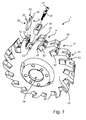
- the cutter system 1 is illustrated in Figure 1 .
- the cutter system 1 comprises a cylindrical cutter head 10 provided with a plurality of slots 11.
- the slots 11 extend in a direction transverse to the periphery of the cutter head 10.
- the slots 11 extend in a direction normal to the periphery of the cutter head 10.
- Each slot 11 is defined by opposite side wall surfaces 12, 13.
- the cutter head 10 is provided with a through hole 14 along its center axis.
- the cutter head 10 can by means of the through hole 14 be arranged on a shaft in a cutter machine.
- An insert knife 20 is provided in each of the slots 11.
- the insert knife 20 is wedged in the slot 11 by means of a wedge element 30.
- the insert knife 20 has a flat shape with a first surface 26 and an opposite second surface 27.
- the insert knife 20 is arranged in an outward direction as seen in a cross-section of the cylindrical cutter head 10.
- the insert knife 20 thus extends in the outward direction.
- the orientation direction of the insert knife 20 is defined as the direction in which the insert knife 20 extends which is the same as the outward direction when the insert knife 20 is mounted on the cutter head 10.
- the insert knife 20 is arranged with its first surface 26 abutting the first of the opposite side wall surfaces 12 of the slot 11.
- the first of the opposite side wall surfaces 12 forms a support surface for the insert knife 20.
- the wedge element 30 is arranged between the second surface 27 of the insert knife 20 and the second of the opposite side wall surfaces 13 of the slot 11.
- the wedge element 30 is fixed to the cutter head 10 by means of screws 31 which are inserted through the wedge element 30 and into the cutter head 10 in an inward direction as seen in a cross-section of the cylindrical cutter head 10.
- the insert knife 20 comprises a cutting edge 23 which in this embodiment is divided into two cutting edge portions.
- the insert knife 20 is arranged such that the cutting edge 23 protrudes past the first of the opposite side wall surfaces 12 of the slot 11 as seen in the outward direction.
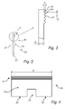
- the insert knife 20 is seen from the side in Figure 2 .
- the profiles of the first surface 26 and the opposite second surface 27 are illustrated.
- the second surface 27 is flat.
- the first surface 26 comprises a ridged portion 21 and a flat portion 22.
- the ridged portion 21 and the flat portion 22 are arranged adjacent each other.
- the ridged portion 21 is arranged beyond the flat portion 27 in view of the cutting edge 23.
- FIG. 3 An enlargement of the indicated area in Figure 2 is illustrated in Figure 3 .
- the ridged portion 21 comprises a plurality of ridges 24.
- the insert knife 20 is oriented such that the flat portion 22 is arranged farther away than the ridged portion 21.
- the cutter head 10 is provided with a grooved portion 15.
- the grooved portion 15 comprises grooves which are formed complementary to the ridges 24. Thus, the ridges 24 can be received by the grooves.
- the grooved portion 15 forms part of the first of the opposite side wall surfaces 12 of the slot 11.
- the first surface 26 of the insert knife 20 abuts the first of the opposite side wall surfaces 12 of the slot 11 by that at least some of the plurality of ridges 24 is received in the complementary grooves of the grooved portion 15 and by that the flat second portion 22 abuts a flat portion of the first of the opposite side wall surfaces 12.
- the invention is based on the realization that the combination of the ridged first portion 21 and the flat second portion 22 provides improved position stability for insert knife 20.
- the improved position stability resides in that the plurality of ridges 24, when received in the grooves of the grooved portion 15, provides position stability in the outward direction of the cutter head 10; and that the flat second portion 22 provides position stability in view of the rotational direction of the cutter head 10.
- the ridges 24 of the ridged first portion 21 bears strains on the insert knife 20 in the outward direction and the flat second portion 22 bears strains on the insert knife 20 in the rotational direction.
- the combination improves the overall position stability in relation to an insert knife having only one of these types of portions as contact surface against a support surface of a cutter head.
- the insert knife 20 may fit in a non-optimal manner in that small spaces are formed between the grooved portion 15 and the ridged portion 21. These small spaces do not affect the position stability in the outward direction as much as the position stability in the rotational direction which can be notably reduced, leading to a rugged surface finish in the work piece.
- the cutter system 1 and the insert knife 20 therein can stand a higher degree of misfit between the ridged first portion 21 and the grooved portion 15 thanks to the flat portion 22 which maintains the position stability in view of the rotational direction.
- the grooved portion 15 does not need to be maintained with respect to its precision to such a high degree and the insert knife 20 can be moved between different grooved portions, within the same or between different cutter heads, with less impact on the position stability of the insert knife 20.
- the ridged first portion 21 may also permit a successively adjustment of the insert knife 20 in the outward direction of the cutter head 10.
- One way to enable such an adjustment is to locate the grooves in the grooved portion 15 slightly above a bottom surface of the slot 11.
- a space 16 is formed, as seen in the outward direction, between the insert knife 20 and the bottom surface of the slot 11.
- the insert knife 20 can thereby be adjusted inwards in order to set how much the cutting edge 23 should protrude past the first of the opposite side wall surfaces 12.
- the insert knife 20 may be set in the lowermost position when mounted for the first time, and successively be adjusted outwards over time when the cutting edge 23 is gradually worn down.
- the number of ridges 24 is five in this embodiment.
- the number of ridges is defined as the number of peaks in the ridged portion 21, when the insert knife 20 is seen from the side as in Figure 3 .
- the ridged portion 21 comprises peaks and valleys.
- a number of ridges 24 in the interval of 2-7 is advantageous in view of the insert knife's 20 position stability when mounted on the cutter head 10.
- a number in this interval may provide particularly satisfactory position stability in the outward direction while not affecting the position stability in the rotational direction to a high degree even if a misfit exists between the ridged portion 21 and the grooves in the support surface.
- a good balance between position stability in the outward direction and high level of fail safety is provided.
- Each ridge 24 protrudes from the insert knife 20 when viewed from the side. Each ridge 24 also extends along the first surface 26 of the insert knife 20. The ridged portion 21 thus forms a rippled surface portion.
- each ridge 24 protrudes from the first surface 26 of the insert knife 20 in a direction normal to the first surface 26. Moreover, each ridge extends along the first surface 26 of the insert knife 20 in a direction perpendicular to the outward direction. In other words, the ridges 24 extend along the viewing direction of Figure 3 . The ridges 24 extend in parallel.
- the ridges 24 are having a height D, the height D being measured from the bottom of a valley in between two ridges to the top of a ridge.
- the height D is preferably not more than 4 mm. It has been realized that ridges with a height of maximum 4 mm provides a good stability in the outward direction. A height above 4 mm is not preferred since the mounting precision in the axial direction will be less accurate for heights above 4 mm.
- Each ridge 24 has a width C, defined by the distance between the centers of two adjacent valleys, of 1.5 to 2 mm.
- the insert knife 20 has a thickness A of 3 - 4 mm as measured at the flat portion 27. However, it is to be noticed that other insert knife thicknesses are also possible to use.
- Figure 4 is a view towards the first surface 26 of the insert knife 20.
- the ridges of the ridged first portion 21 extend along the whole width E, which is 60 mm in this embodiment.
- the insert knife may have another width. The width of the insert knife depends on the geometry of the cutter head.
- the cutting edge 23 is provided with a slit 25.
- the slit 25 extends into the flat portion 22 of the insert knife 20.
- the cutting edge 23 and the design of the slit 25 define the profile which is formed in the work piece.
- the insert knife 20 may provide an elongated projection, defined by the slit 25, along e.g. an edge of a wood board.
- FIG 5 illustrate another embodiment of a cutter system 2.
- the cutter system 2 comprises a cylindrical cutter head 50 provided with circumferential slots 51, i.e. slots 51 extending transverse the circumference of the cylindrical cutter head 50.
- insert knives 52 are inserted into the slots 51.
- Each insert knife 52 is wedged by means of a wedge element 53.
- Each insert knife 52 is arranged in an outward direction as seen in a cross-section of the cylindrical cutter head 50.
- outward direction as seen in a cross-section of the cylindrical cutter head 10 is meant a direction transverse the periphery of the cylindrical cutter head 10.
- the outward direction is a non-tangential direction of the cylindrical cutter head 10.
- Figure 5 illustrates three examples of outward directions 54a, 54b, 54c wherein an insert knife 52 is arranged to extend in each of these direction.
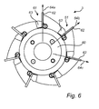
- FIG 6 illustrates yet another embodiment of a cutter system 3.
- the cutter system 3 comprises a cutter head 60 with insert knives 62 which are wedged into slots 61 by means of wedge elements 63. This construction is similar to the construction disclosed in connection to Figure 1 .
- the insert knives 62 are arranged to extend in a specific outward direction being the radial direction of the cutter head 60.
- Three examples of the specific outward direction being the radial direction 64a, 64b, 64c are illustrated.
- FIG. 7 A cutter system 7 is illustrated in Figure 7 .
- the cutter system 7 comprises a cutter head 70 provided with insert knives 72 which are wedged into slots 71 by means of wedge elements 73. This construction is similar to the construction disclosed in connection to Figure 1 .
- One of the insert knives 72 are illustrated as seen towards its first surface in Figure 8 .
- the first surface is the one which is arranged to abut a support surface of the cutter head 70.
- One of two opposite side walls of each slot 71 forms a support surface for the insert knife 72 arranged in the slot, in similar to previously disclosed embodiments.
- the insert knife 72 is provided with a recess 79 being open towards a side of the insert knife 72.
- the recess 79 may be formed, as in this embodiment, by cutting out the corner of the originally rectangular shaped insert knife 72, as seen towards its first surface.
- the recess 79 is provided in the ridged portion 76 of the insert knife 72.
- a screw 75 is inserted into the cutter head 70 at the recess 79 of each insert knife 72.
- the screw 75 is inserted essentially parallel to the axial direction of the cylindrical cutter head 70.
- the screw 75 is arranged at a position such that a part of the screw 75, formed by a part of the screw head in the illustrated embodiment, is received in the recess 79 of the insert knife 72.
- the insert knife 72 is thereby prevented from moving sideways in a direction parallel to the axial direction of the cylindrical cutter head 70.
- the insert knife 72 may be provided with a further recess (not illustrated) at the opposite corner in the ridged portion 76 as seen towards the first surface of the insert knife 72. Similar to the arrangement of the screw 75 from one base side of the cylindrical cutter head 70, a further screw may be arranged from the other base side. The insert knife 72 is thereby prevented from moving sideways in both directions parallel to the axial direction of the cylindrical cutter head 70.
- the illustrated embodiments show a ridged portion with ridges that are raised above the level of the flat surface.
- the ridged portion can lowered into and below the level of the flat surface.
Abstract
Description
- The present application relates to the field of cutter systems for profile milling, and in particular to the field of insert knives for use in profile cutter heads in such systems.
- Profile milling is well known in the art. Cutter systems for profile milling are available in many forms depending on for example the application, the milling technique to be used and the material to be profiled. A cutter system comprises, in general, a cutter head provided with one or more cutting edges in some form.
- The present application will relate to a type of cutter head which is provided with one or more exchangeable insert knives. Each insert knife may be provided in a circumferential slot of the cutter head. An insert knife typically comprises a cutting edge which protrudes from the cutter head when the insert knife is mounted thereto.
- When a work piece is fed through the milling machine, the rotating cutter head forms a profile with a design that is defined by the form of the insert knife with its cutting edge. The profile could for example be a rounded profile along an edge portion of a wood board.
- The work piece material can be for example metal, wood or plastics.
- The insert knives can be fixed to the cutter head in different ways. One way is to attach the insert knife by means of a screw or the like which is arranged through the insert knife and into the cutter head material. Another way is to wedge the insert knife in a slot of the cutter head by means of a wedge element. The insert knife may in the latter case be arranged along a side wall of the slot and the wedge element may be arranged between the insert knife and an opposite side wall of the slot.
- When using a wedge element for fixing the insert knife to the cutter head problems with position stability of the insert knife during use of the cutter head for profile milling may occur. Hence, there is a need for an improved insert knife and an improved cutter system comprising a cutter head and an insert knife.
- An object of the present invention is to provide an improved insert knife for a cutter head and an improved cutter system comprising a cutter head and the improved insert knife. A particular object of the invention is to provide an insert knife with improved position stability when inserted into a cutter head and to provide a cutter system comprising a cutter head and an insert knife wherein the position stability of the insert knife is improved.
- According to a first aspect of the invention a cutter system for profile milling is provided. The cutter system comprises a cylindrical cutter head provided with a slot transverse its circumference, the slot having opposite side wall surfaces, and an insert knife arranged in the slot and extending in an outward direction as seen in a cross-section of the cutter head. The insert knife comprising a first surface abutting a first of the opposite side wall surfaces of the slot, the first surface having a ridged first portion comprising a plurality of ridges and a flat second portion, and a cutting edge which protrudes past the first of the opposite side wall surfaces of the slot as seen in the outward direction. The insert knife is oriented with the flat second portion farther out than the ridged first portion. The insert knife is oriented such that the ridges of the ridged first portion are received in complementary grooves in the first of the opposite side wall surfaces of the slot.
- The invention is based on the realization that a combination of the ridged portion and the flat portion provides improved position stability for the insert knife. The improved position stability resides in that the ridged portion provides stability in view of the outward direction of the cutter head and that the flat portion provides stability in view of the rotational direction of the cutter head. In other words, the ridges of the ridge portion bears strains on the insert knife in the outward direction and the flat portion bears strains on the insert knife in the rotational direction. This combination improves the position stability in relation to an insert knife having only one of these types of portions as contact surface against the support surface of the cutter head.
- The ridged portion may also permit a successively adjustment of the insert knife in the outward direction of the cutter head.
- The use of a ridged portion on the insert knife requires that the cutter head, which with the insert knife is to be used, is provided with complementary grooves for receiving the ridges. The grooves are typically formed by use of a template based on the particular type of insert knife. Due to for example wear or lack of precision when forming the grooves, the insert knife may fit in a non-optimal manner by that small spaces are formed between the grooved portion of the support surface and the ridged portion of the insert knife. These small spaces do not affect the position stability in the outward direction as much as the position stability in the rotational direction which can be notably reduced, leading to a rugged surface finish in the work piece. According to the invention, the cutter system and the insert knife therein can stand a higher degree of misfit between the ridged first portion and the grooved portion in the support surface thanks to the flat portion which maintains the stability in view of the rotational direction. Thus, the grooved portion does not need to be maintained with respect to its precision to such a high degree and insert knives can be moved between different grooved portions, within the same or between different cutter heads, with less impact on the position stability of the insert knife.
- By outward direction in view of the center axis of the cutter head is meant a direction transverse the periphery of the cylindrical cutter head. In other words, the outward direction is any direction which is not tangential to the cylindrical cutter head. In one embodiment, the outward direction is a radial direction of the cutter head.
- The cutter system may comprise a wedge element arranged between the second of the opposite side wall surfaces of the slot and a second surface of the insert knife opposite to the first surface of the insert knife. The insert knife is thereby wedged in the slot.
- In one embodiment, the ridged first portion has 2-7 ridges. It has been realized that a number of ridges in this interval provides increased position stability in view of the outward direction while not affecting the position stability in the rotational direction to a high degree if there is a misfit between the ridged portion and the grooves in the support surface. Thus, a good balance between stability in the outward direction and high level of fail safety is provided.
- In one embodiment, the plurality of ridges have a height of not more than 4 mm, the height being measured from the bottom of a valley in between two ridges to the top of a ridge. It has been realized that ridges with a height in this interval provides a good stability in the outward direction. A height above 4 mm is not preferred since the mounting precision in the axial direction will be less accurate for heights above 4 mm.
- In one embodiment the plurality of ridges protrude from the first surface of the insert knife in a direction normal to said first surface. Manufacturing of the insert knife and of the cutter head, in particular with respect to providing the grooves in the support surface, may thus be facilitated.
- In one embodiment, the plurality of ridges extends along the first surface of the insert knife in a direction perpendicular to the outward direction of the insert knife. Forces in the outward direction may thereby be counteracted in an optimal manner.
- The cutter system is preferably arranged for profile milling in wood materials.
- According to a second aspect of the invention an insert knife for a cylindrical cutter head is provided. The insert knife comprises a first surface arranged to abut a support surface of the cutter head, the first surface having a ridged first portion, comprising a plurality of ridges, and a flat second portion and a cutting edge. The insert knife is arranged to extend in an outward direction as seen in a cross-section of the cutter head with the flat second portion farther out than the ridged first portion, and with the cutting edge protruding past the support surface as seen in the outward direction. The insert knife is arranged to be oriented such that the ridges of the ridged first portion are received in complementary grooves in the support surface of the cutter head.
- The support surface of the cutter head may be formed by a side wall in a slot of said cutter head.
- The above disclosed features and corresponding advantages of the first aspect is also applicable to this second aspect. To avoid undue repetition, reference is made to the discussion above.
- It is noted that the invention relates to all possible combinations of features recited in the claims.
- This and other aspects of the present invention will now be described in more detail, with reference to the enclosed drawings showing embodiments of the invention.
-
Figure 1 is a partly exploded view of a cutter head with insert knives according to an embodiment. -
Figure 2 is a view from the side of one of the insert knives inFigure 1 . -
Figure 3 is an enlarged view of a part of the insert knife inFigure 2 . -
Figure 4 is a view towards a first surface of the insert knife inFigure 1 . -
Figures 5 and6 are view from the side of different embodiments of a cutter head. -
Figure 7 illustrates yet another embodiment of a cutter head. -
Figure 8 is a view towards a first surface of one of the insert knives inFigure 7 . - The present invention will now be described more fully hereinafter with reference to the accompanying drawings, in which currently preferred embodiments of the invention are shown. This invention may, however, be embodied in many different forms and should not be construed as limited to the embodiments set forth herein. Rather, these embodiments are provided for thoroughness and completeness, and for fully conveying the scope of the invention to the skilled person.
- The invention will be disclosed with reference to a profile cutter system. The invention is however applicable to other types of cutter systems as well where insert knives are utilized.
- To start with, the general construction of a
cutter system 1 for profile milling according to one embodiment will be disclosed with reference toFigures 1-3 . - The
cutter system 1 is illustrated inFigure 1 . Thecutter system 1 comprises acylindrical cutter head 10 provided with a plurality ofslots 11. Theslots 11 extend in a direction transverse to the periphery of thecutter head 10. In this embodiment, theslots 11 extend in a direction normal to the periphery of thecutter head 10. Eachslot 11 is defined by opposite side wall surfaces 12, 13. Thecutter head 10 is provided with a throughhole 14 along its center axis. Thecutter head 10 can by means of the throughhole 14 be arranged on a shaft in a cutter machine. - An
insert knife 20 is provided in each of theslots 11. When describing the construction of eachinsert knife 20, reference will be given to asingle insert knife 20. The construction applies to eachinsert knife 20 in thecutter system 1. - The
insert knife 20 is wedged in theslot 11 by means of awedge element 30. Theinsert knife 20 has a flat shape with afirst surface 26 and an oppositesecond surface 27. - The
insert knife 20 is arranged in an outward direction as seen in a cross-section of thecylindrical cutter head 10. Theinsert knife 20 thus extends in the outward direction. The orientation direction of theinsert knife 20 is defined as the direction in which theinsert knife 20 extends which is the same as the outward direction when theinsert knife 20 is mounted on thecutter head 10. - The
insert knife 20 is arranged with itsfirst surface 26 abutting the first of the opposite side wall surfaces 12 of theslot 11. The first of the opposite side wall surfaces 12 forms a support surface for theinsert knife 20. Thewedge element 30 is arranged between thesecond surface 27 of theinsert knife 20 and the second of the opposite side wall surfaces 13 of theslot 11. Thewedge element 30 is fixed to thecutter head 10 by means ofscrews 31 which are inserted through thewedge element 30 and into thecutter head 10 in an inward direction as seen in a cross-section of thecylindrical cutter head 10. - The
insert knife 20 comprises acutting edge 23 which in this embodiment is divided into two cutting edge portions. Theinsert knife 20 is arranged such that thecutting edge 23 protrudes past the first of the opposite side wall surfaces 12 of theslot 11 as seen in the outward direction. - The
insert knife 20 is seen from the side inFigure 2 . The profiles of thefirst surface 26 and the oppositesecond surface 27 are illustrated. Thesecond surface 27 is flat. Thefirst surface 26 comprises a ridgedportion 21 and aflat portion 22. The ridgedportion 21 and theflat portion 22 are arranged adjacent each other. The ridgedportion 21 is arranged beyond theflat portion 27 in view of thecutting edge 23. - An enlargement of the indicated area in
Figure 2 is illustrated inFigure 3 . The ridgedportion 21 comprises a plurality ofridges 24. Returning toFigure 1 , it can be seen that theinsert knife 20 is oriented such that theflat portion 22 is arranged farther away than the ridgedportion 21. - The
cutter head 10 is provided with agrooved portion 15. The groovedportion 15 comprises grooves which are formed complementary to theridges 24. Thus, theridges 24 can be received by the grooves. The groovedportion 15 forms part of the first of the opposite side wall surfaces 12 of theslot 11. - The
first surface 26 of theinsert knife 20 abuts the first of the opposite side wall surfaces 12 of theslot 11 by that at least some of the plurality ofridges 24 is received in the complementary grooves of the groovedportion 15 and by that the flatsecond portion 22 abuts a flat portion of the first of the opposite side wall surfaces 12. - The invention is based on the realization that the combination of the ridged
first portion 21 and the flatsecond portion 22 provides improved position stability forinsert knife 20. The improved position stability resides in that the plurality ofridges 24, when received in the grooves of the groovedportion 15, provides position stability in the outward direction of thecutter head 10; and that the flatsecond portion 22 provides position stability in view of the rotational direction of thecutter head 10. In other words, theridges 24 of the ridgedfirst portion 21 bears strains on theinsert knife 20 in the outward direction and the flatsecond portion 22 bears strains on theinsert knife 20 in the rotational direction. The combination improves the overall position stability in relation to an insert knife having only one of these types of portions as contact surface against a support surface of a cutter head. - Due to for example wear or lack of precision when forming the grooves of the grooved
portion 15, theinsert knife 20 may fit in a non-optimal manner in that small spaces are formed between thegrooved portion 15 and the ridgedportion 21. These small spaces do not affect the position stability in the outward direction as much as the position stability in the rotational direction which can be notably reduced, leading to a rugged surface finish in the work piece. According to the invention, thecutter system 1 and theinsert knife 20 therein can stand a higher degree of misfit between the ridgedfirst portion 21 and the groovedportion 15 thanks to theflat portion 22 which maintains the position stability in view of the rotational direction. Thus, the groovedportion 15 does not need to be maintained with respect to its precision to such a high degree and theinsert knife 20 can be moved between different grooved portions, within the same or between different cutter heads, with less impact on the position stability of theinsert knife 20. - The ridged
first portion 21 may also permit a successively adjustment of theinsert knife 20 in the outward direction of thecutter head 10. One way to enable such an adjustment is to locate the grooves in the groovedportion 15 slightly above a bottom surface of theslot 11. When theinsert knife 20 is oriented such that the ridgedportion 21 is aligned with the groovedportion 15, aspace 16 is formed, as seen in the outward direction, between theinsert knife 20 and the bottom surface of theslot 11. Theinsert knife 20 can thereby be adjusted inwards in order to set how much thecutting edge 23 should protrude past the first of the opposite side wall surfaces 12. Alternatively, theinsert knife 20 may be set in the lowermost position when mounted for the first time, and successively be adjusted outwards over time when thecutting edge 23 is gradually worn down. - Going more into detail, the construction of the
insert knife 20 of this embodiment will now be disclosed with reference toFigure 3 . - The number of
ridges 24 is five in this embodiment. The number of ridges is defined as the number of peaks in the ridgedportion 21, when theinsert knife 20 is seen from the side as inFigure 3 . The ridgedportion 21 comprises peaks and valleys. - It has been realized a number of
ridges 24 in the interval of 2-7 is advantageous in view of the insert knife's 20 position stability when mounted on thecutter head 10. A number in this interval may provide particularly satisfactory position stability in the outward direction while not affecting the position stability in the rotational direction to a high degree even if a misfit exists between the ridgedportion 21 and the grooves in the support surface. Thus, a good balance between position stability in the outward direction and high level of fail safety is provided. - Each
ridge 24 protrudes from theinsert knife 20 when viewed from the side. Eachridge 24 also extends along thefirst surface 26 of theinsert knife 20. The ridgedportion 21 thus forms a rippled surface portion. - In the illustrated embodiment, each
ridge 24 protrudes from thefirst surface 26 of theinsert knife 20 in a direction normal to thefirst surface 26. Moreover, each ridge extends along thefirst surface 26 of theinsert knife 20 in a direction perpendicular to the outward direction. In other words, theridges 24 extend along the viewing direction ofFigure 3 . Theridges 24 extend in parallel. - The
ridges 24 are having a height D, the height D being measured from the bottom of a valley in between two ridges to the top of a ridge. The height D is preferably not more than 4 mm. It has been realized that ridges with a height of maximum 4 mm provides a good stability in the outward direction. A height above 4 mm is not preferred since the mounting precision in the axial direction will be less accurate for heights above 4 mm. - Each
ridge 24 has a width C, defined by the distance between the centers of two adjacent valleys, of 1.5 to 2 mm. - The
insert knife 20 has a thickness A of 3 - 4 mm as measured at theflat portion 27. However, it is to be noticed that other insert knife thicknesses are also possible to use. -
Figure 4 is a view towards thefirst surface 26 of theinsert knife 20. The ridges of the ridgedfirst portion 21 extend along the whole width E, which is 60 mm in this embodiment. However, it is to be noticed that the insert knife may have another width. The width of the insert knife depends on the geometry of the cutter head. - The
cutting edge 23 is provided with aslit 25. Theslit 25 extends into theflat portion 22 of theinsert knife 20. Thecutting edge 23 and the design of theslit 25 define the profile which is formed in the work piece. In this embodiment, theinsert knife 20 may provide an elongated projection, defined by theslit 25, along e.g. an edge of a wood board. -
Figure 5 illustrate another embodiment of acutter system 2. Thecutter system 2 comprises acylindrical cutter head 50 provided withcircumferential slots 51, i.e.slots 51 extending transverse the circumference of thecylindrical cutter head 50. With similar construction as disclosed in connection toFigure 1 , insertknives 52 are inserted into theslots 51. Eachinsert knife 52 is wedged by means of awedge element 53. - Each
insert knife 52 is arranged in an outward direction as seen in a cross-section of thecylindrical cutter head 50. By outward direction as seen in a cross-section of thecylindrical cutter head 10 is meant a direction transverse the periphery of thecylindrical cutter head 10. In other words, the outward direction is a non-tangential direction of thecylindrical cutter head 10.Figure 5 illustrates three examples ofoutward directions insert knife 52 is arranged to extend in each of these direction. -
Figure 6 illustrates yet another embodiment of acutter system 3. Thecutter system 3 comprises acutter head 60 withinsert knives 62 which are wedged intoslots 61 by means ofwedge elements 63. This construction is similar to the construction disclosed in connection toFigure 1 . - The
insert knives 62 are arranged to extend in a specific outward direction being the radial direction of thecutter head 60. Three examples of the specific outward direction being theradial direction - Another embodiment of a
cutter system 7 will now be disclosed with reference toFigures 7 and 8 . Acutter system 7 is illustrated inFigure 7 . Thecutter system 7 comprises acutter head 70 provided withinsert knives 72 which are wedged intoslots 71 by means ofwedge elements 73. This construction is similar to the construction disclosed in connection toFigure 1 . - One of the
insert knives 72 are illustrated as seen towards its first surface inFigure 8 . The first surface is the one which is arranged to abut a support surface of thecutter head 70. One of two opposite side walls of eachslot 71 forms a support surface for theinsert knife 72 arranged in the slot, in similar to previously disclosed embodiments. - The
insert knife 72 is provided with arecess 79 being open towards a side of theinsert knife 72. Therecess 79 may be formed, as in this embodiment, by cutting out the corner of the originally rectangular shapedinsert knife 72, as seen towards its first surface. Therecess 79 is provided in the ridgedportion 76 of theinsert knife 72. - When the
insert knife 72 is arranged in thecutter head 70, ascrew 75 is inserted into thecutter head 70 at therecess 79 of eachinsert knife 72. Thescrew 75 is inserted essentially parallel to the axial direction of thecylindrical cutter head 70. Thescrew 75 is arranged at a position such that a part of thescrew 75, formed by a part of the screw head in the illustrated embodiment, is received in therecess 79 of the insert knife 72.Theinsert knife 72 is thereby prevented from moving sideways in a direction parallel to the axial direction of thecylindrical cutter head 70. - The
insert knife 72 may be provided with a further recess (not illustrated) at the opposite corner in the ridgedportion 76 as seen towards the first surface of theinsert knife 72. Similar to the arrangement of thescrew 75 from one base side of thecylindrical cutter head 70, a further screw may be arranged from the other base side. Theinsert knife 72 is thereby prevented from moving sideways in both directions parallel to the axial direction of thecylindrical cutter head 70. - The illustrated embodiments show a ridged portion with ridges that are raised above the level of the flat surface. In alternative embodiments, the ridged portion can lowered into and below the level of the flat surface.
- It is understood that these embodiments may be combined or altered within the scope of the claims.
Claims (13)
- A cutter system for profile milling, the cutter system comprising:a cylindrical cutter head (10, 50, 60, 70) provided with a slot (11, 51, 61, 71) transverse its circumference, the slot (11, 51, 61, 71) having opposite side wall surfaces (12, 13), andan insert knife (20, 52, 62, 72) arranged in the slot (11, 51, 61, 71) and extending in an outward direction (54a, 54b, 54c, 64a, 64b, 64c) as seen in a cross-section of the cutter head (10, 50, 60, 70), the insert knife (20, 52, 62, 72) comprising:a first surface (26) abutting a first of the opposite side wall surfaces (12) of the slot (11, 51, 61, 71), the first surface (12) having a ridged first portion (21), comprising a plurality of ridges (24), and a flat second portion (22), anda cutting edge (23) which protrudes past the first of the opposite side wall surfaces (12) of the slot as seen in the outward direction (54a, 54b, 54c, 64a, 64b, 64c),wherein the insert knife (20, 52, 62, 72) is oriented with the flat second portion (22) farther out than the ridged first portion (21), andwherein the insert knife (20, 52, 62, 72) is oriented such that the ridges (24) of the ridged first portion (21) are received in complementary grooves in the first of the opposite side wall surfaces (12) of the slot (11, 51, 61, 71).
- The cutter system according to claim 1, further comprising:a wedge element (30, 53, 63, 73) arranged between the second of the opposite side wall surfaces (13) of the slot (11, 51, 61, 71) and a second surface (27) of the insert knife (20, 52, 62, 72) opposite to the first surface (26) of the insert knife (20, 52, 62, 72),whereby the insert knife (20, 52, 62, 72) is wedged in the slot (11, 51,61,71).
- A cutter system according to any one of claims 1-2, wherein the ridged first portion (21) has 2-7 ridges.
- The cutter system according to any one of claims 1-3, wherein the ridges (24) of the ridged first portion (21) have a height (D) of not more than 4 mm.
- The cutter system according to any one of claims 1-4, wherein the plurality of ridges (24) extends along the first surface (26) of the insert knife (20, 52, 62, 72) in a direction perpendicular to the outward direction (54a, 54b, 54c, 64a, 64b, 64c).
- The cutter system according to any one of claims 1-6, wherein the plurality of ridges (24) protrudes from the first surface (26) of the insert knife (20, 52, 62, 72) in a direction normal to said first surface (26).
- The insert knife according to any one of claims 1-5, wherein the outward direction is a radial direction (64a, 64b, 64c) of the cutter head (60).
- An insert knife for a cylindrical cutter head (10, 50, 60, 70), the insert knife comprising:a first surface (26) arranged to abut a support surface (12) of the cutter head, the first surface (26) having a ridged first portion (21), comprising a plurality of ridges (24), and a flat second portion (22), anda cutting edge (23),wherein the insert knife is arranged to extend in an outward direction (54a, 54b, 54c, 64a, 64b, 64c) as seen in a cross-section of the cutter head (10, 50, 60, 70) with the flat second portion (22) farther out than the ridged first portion (21), and with the cutting edge (23) protruding past the support surface (12) as seen in the outward direction (54a, 54b, 54c, 64a, 64b, 64c), andwherein the insert knife is arranged to be oriented such that the ridges (24) of the ridged first portion (21) are received in complementary grooves in the support surface (12) of the cutter head (10, 50, 60, 70).
- The insert knife according to claim 8, wherein the ridged first portion (21) has 2-7 ridges.
- The insert knife according to any one of claims 8-9, wherein the ridges of the ridged first portion (21) have a height (D) of not more than 4 mm.
- The insert knife according any one of claims 8-10, wherein the support surface (12) of the cutter head is formed by a side wall in a slot (11, 51, 61, 71) of said cutter head (10, 50, 60, 70).
- The insert knife according to any one of claims 8-11, wherein the plurality of ridges (24) extends along the first surface (26) of the insert knife (20, 52, 62, 72) in a direction perpendicular to the outward direction (54a, 54b, 54c, 64a, 64b, 64c).
- The insert knife according to any one of claims 8-13, wherein the plurality of ridges (24) protrudes from the first surface (26) of the insert knife (20, 52, 62, 72) in a direction normal to said first surface (26).
The insert knife according to any one of claims 8-12, wherein the outward direction is a radial direction (64a, 64b, 64c) of the cutter head (60).
Priority Applications (6)
| Application Number | Priority Date | Filing Date | Title |
|---|---|---|---|
| PT141806836T PT2985100T (en) | 2014-08-12 | 2014-08-12 | A cutter system and an insert knife for a cutter head |
| PL14180683T PL2985100T3 (en) | 2014-08-12 | 2014-08-12 | A cutter system for profile milling |
| LTEP14180683.6T LT2985100T (en) | 2014-08-12 | 2014-08-12 | A cutter system for profile milling |
| DK14180683.6T DK2985100T3 (en) | 2014-08-12 | 2014-08-12 | Cutting system for profile milling |
| EP14180683.6A EP2985100B1 (en) | 2014-08-12 | 2014-08-12 | A cutter system for profile milling |
| ES14180683T ES2776184T3 (en) | 2014-08-12 | 2014-08-12 | A cutting system for milling profiles |
Applications Claiming Priority (1)
| Application Number | Priority Date | Filing Date | Title |
|---|---|---|---|
| EP14180683.6A EP2985100B1 (en) | 2014-08-12 | 2014-08-12 | A cutter system for profile milling |
Publications (2)
| Publication Number | Publication Date |
|---|---|
| EP2985100A1 true EP2985100A1 (en) | 2016-02-17 |
| EP2985100B1 EP2985100B1 (en) | 2019-12-11 |
Family
ID=51357733
Family Applications (1)
| Application Number | Title | Priority Date | Filing Date |
|---|---|---|---|
| EP14180683.6A Active EP2985100B1 (en) | 2014-08-12 | 2014-08-12 | A cutter system for profile milling |
Country Status (6)
| Country | Link |
|---|---|
| EP (1) | EP2985100B1 (en) |
| DK (1) | DK2985100T3 (en) |
| ES (1) | ES2776184T3 (en) |
| LT (1) | LT2985100T (en) |
| PL (1) | PL2985100T3 (en) |
| PT (1) | PT2985100T (en) |
Cited By (5)
| Publication number | Priority date | Publication date | Assignee | Title |
|---|---|---|---|---|
| US20170348695A1 (en) * | 2016-06-07 | 2017-12-07 | Eco Green Equipment, Llc | Secondary shredder |
| CN108453906A (en) * | 2018-03-29 | 2018-08-28 | 中钢集团新型材料(浙江)有限公司 | A kind of graphite material fracture toughness test grooving tool, equipment and grooving method |
| CN109719811A (en) * | 2019-03-14 | 2019-05-07 | 天津广顺锐林木工刀具科技有限公司 | A kind of timber production carving cutter |
| CN110560767A (en) * | 2019-07-24 | 2019-12-13 | 富曜半导体(昆山)有限公司 | high-speed cutting tool for numerical control milling of aluminum alloy |
| CN114871484A (en) * | 2022-06-09 | 2022-08-09 | 常州众天孵化器有限公司 | Cylindrical milling cutter and positioning device thereof |
Citations (3)
| Publication number | Priority date | Publication date | Assignee | Title |
|---|---|---|---|---|
| US1691983A (en) * | 1926-07-30 | 1928-11-20 | Frank P Miller | Rotary cutter |
| EP0103480A2 (en) * | 1982-09-11 | 1984-03-21 | Wadkin Public Limited Company | Cutterblock blade anchorage |
| WO2005080037A1 (en) * | 2004-02-20 | 2005-09-01 | Sandvik Intellectual Property Ab | Slot milling cutter |
-
2014
- 2014-08-12 DK DK14180683.6T patent/DK2985100T3/en active
- 2014-08-12 PT PT141806836T patent/PT2985100T/en unknown
- 2014-08-12 EP EP14180683.6A patent/EP2985100B1/en active Active
- 2014-08-12 LT LTEP14180683.6T patent/LT2985100T/en unknown
- 2014-08-12 PL PL14180683T patent/PL2985100T3/en unknown
- 2014-08-12 ES ES14180683T patent/ES2776184T3/en active Active
Patent Citations (3)
| Publication number | Priority date | Publication date | Assignee | Title |
|---|---|---|---|---|
| US1691983A (en) * | 1926-07-30 | 1928-11-20 | Frank P Miller | Rotary cutter |
| EP0103480A2 (en) * | 1982-09-11 | 1984-03-21 | Wadkin Public Limited Company | Cutterblock blade anchorage |
| WO2005080037A1 (en) * | 2004-02-20 | 2005-09-01 | Sandvik Intellectual Property Ab | Slot milling cutter |
Cited By (7)
| Publication number | Priority date | Publication date | Assignee | Title |
|---|---|---|---|---|
| US20170348695A1 (en) * | 2016-06-07 | 2017-12-07 | Eco Green Equipment, Llc | Secondary shredder |
| CN108453906A (en) * | 2018-03-29 | 2018-08-28 | 中钢集团新型材料(浙江)有限公司 | A kind of graphite material fracture toughness test grooving tool, equipment and grooving method |
| CN108453906B (en) * | 2018-03-29 | 2019-03-26 | 中钢集团新型材料(浙江)有限公司 | A kind of graphite material fracture toughness test grooving tool, equipment and grooving method |
| CN109719811A (en) * | 2019-03-14 | 2019-05-07 | 天津广顺锐林木工刀具科技有限公司 | A kind of timber production carving cutter |
| CN110560767A (en) * | 2019-07-24 | 2019-12-13 | 富曜半导体(昆山)有限公司 | high-speed cutting tool for numerical control milling of aluminum alloy |
| CN114871484A (en) * | 2022-06-09 | 2022-08-09 | 常州众天孵化器有限公司 | Cylindrical milling cutter and positioning device thereof |
| CN114871484B (en) * | 2022-06-09 | 2024-01-19 | 常州众天孵化器有限公司 | Cylindrical milling cutter and positioning device thereof |
Also Published As
| Publication number | Publication date |
|---|---|
| LT2985100T (en) | 2020-03-10 |
| PT2985100T (en) | 2020-03-04 |
| ES2776184T3 (en) | 2020-07-29 |
| DK2985100T3 (en) | 2020-03-02 |
| PL2985100T3 (en) | 2020-06-15 |
| EP2985100B1 (en) | 2019-12-11 |
Similar Documents
| Publication | Publication Date | Title |
|---|---|---|
| EP2985100B1 (en) | A cutter system for profile milling | |
| US8465233B2 (en) | Slot-milling tool and slot-milling insert for a slot-milling tool | |
| US6929429B2 (en) | Milling tool and cutting insert therefor | |
| US9144848B2 (en) | Cutting edge exchange type cutting tool | |
| JP4327397B2 (en) | Grooving cutter and cutting insert used therefor | |
| US7819610B2 (en) | Tool for chip removing machining, as well as a cutting insert and a basic body therefor | |
| KR101972178B1 (en) | Octagonal cutting insert having edge portion with variable wedge angle, and cutting tool | |
| JP5363469B2 (en) | Tool for machining chip removal type and its body and indexable cutting insert | |
| US9993884B2 (en) | Double-sided tangential cutting insert | |
| KR101211893B1 (en) | Cutting tool and cartridge for the same | |
| US20200368830A1 (en) | Indexable rotary cutting tool and tool body | |
| KR102029564B1 (en) | T slot cutter | |
| JP2003275919A (en) | Throw-away tip and throw-away cutting tool | |
| KR20130124212A (en) | A milling tool as well as set of milling inserts of a milling tool | |
| JP4382216B2 (en) | Tool for chip break machining | |
| US10391567B2 (en) | Rotary cutting tool and cutting insert therefor | |
| US9505066B2 (en) | Rotary cutting tool with regrindable cutting inserts | |
| RU2638475C2 (en) | Milling cutter | |
| KR20140002630A (en) | Insert | |
| CN101304852A (en) | Cutting tool with stress splitter | |
| KR101238850B1 (en) | Insert and side cutter | |
| US7281885B2 (en) | High-speed milling cutter | |
| JPH04506777A (en) | cutting elements for tools | |
| US4033018A (en) | Indexable milling cutter | |
| RU2562195C1 (en) | Cutter (versions) |
Legal Events
| Date | Code | Title | Description |
|---|---|---|---|
| PUAI | Public reference made under article 153(3) epc to a published international application that has entered the european phase |
Free format text: ORIGINAL CODE: 0009012 |
|
| AK | Designated contracting states |
Kind code of ref document: A1 Designated state(s): AL AT BE BG CH CY CZ DE DK EE ES FI FR GB GR HR HU IE IS IT LI LT LU LV MC MK MT NL NO PL PT RO RS SE SI SK SM TR |
|
| AX | Request for extension of the european patent |
Extension state: BA ME |
|
| 17P | Request for examination filed |
Effective date: 20160817 |
|
| RBV | Designated contracting states (corrected) |
Designated state(s): AL AT BE BG CH CY CZ DE DK EE ES FI FR GB GR HR HU IE IS IT LI LT LU LV MC MK MT NL NO PL PT RO RS SE SI SK SM TR |
|
| RAP1 | Party data changed (applicant data changed or rights of an application transferred) |
Owner name: LSAB SVERIGE AB |
|
| GRAP | Despatch of communication of intention to grant a patent |
Free format text: ORIGINAL CODE: EPIDOSNIGR1 |
|
| STAA | Information on the status of an ep patent application or granted ep patent |
Free format text: STATUS: GRANT OF PATENT IS INTENDED |
|
| INTG | Intention to grant announced |
Effective date: 20190725 |
|
| GRAS | Grant fee paid |
Free format text: ORIGINAL CODE: EPIDOSNIGR3 |
|
| GRAA | (expected) grant |
Free format text: ORIGINAL CODE: 0009210 |
|
| STAA | Information on the status of an ep patent application or granted ep patent |
Free format text: STATUS: THE PATENT HAS BEEN GRANTED |
|
| AK | Designated contracting states |
Kind code of ref document: B1 Designated state(s): AL AT BE BG CH CY CZ DE DK EE ES FI FR GB GR HR HU IE IS IT LI LT LU LV MC MK MT NL NO PL PT RO RS SE SI SK SM TR |
|
| REG | Reference to a national code |
Ref country code: GB Ref legal event code: FG4D |
|
| REG | Reference to a national code |
Ref country code: CH Ref legal event code: EP |
|
| REG | Reference to a national code |
Ref country code: AT Ref legal event code: REF Ref document number: 1211706 Country of ref document: AT Kind code of ref document: T Effective date: 20191215 |
|
| REG | Reference to a national code |
Ref country code: DE Ref legal event code: R096 Ref document number: 602014058152 Country of ref document: DE |
|
| REG | Reference to a national code |
Ref country code: IE Ref legal event code: FG4D |
|
| REG | Reference to a national code |
Ref country code: DK Ref legal event code: T3 Effective date: 20200227 |
|
| REG | Reference to a national code |
Ref country code: PT Ref legal event code: SC4A Ref document number: 2985100 Country of ref document: PT Date of ref document: 20200304 Kind code of ref document: T Free format text: AVAILABILITY OF NATIONAL TRANSLATION Effective date: 20200224 |
|
| REG | Reference to a national code |
Ref country code: FI Ref legal event code: FGE |
|
| REG | Reference to a national code |
Ref country code: NO Ref legal event code: T2 Effective date: 20191211 |
|
| REG | Reference to a national code |
Ref country code: NL Ref legal event code: FP |
|
| REG | Reference to a national code |
Ref country code: SE Ref legal event code: TRGR |
|
| REG | Reference to a national code |
Ref country code: EE Ref legal event code: FG4A Ref document number: E018733 Country of ref document: EE Effective date: 20200220 |
|
| PG25 | Lapsed in a contracting state [announced via postgrant information from national office to epo] |
Ref country code: BG Free format text: LAPSE BECAUSE OF FAILURE TO SUBMIT A TRANSLATION OF THE DESCRIPTION OR TO PAY THE FEE WITHIN THE PRESCRIBED TIME-LIMIT Effective date: 20200311 Ref country code: GR Free format text: LAPSE BECAUSE OF FAILURE TO SUBMIT A TRANSLATION OF THE DESCRIPTION OR TO PAY THE FEE WITHIN THE PRESCRIBED TIME-LIMIT Effective date: 20200312 |
|
| PG25 | Lapsed in a contracting state [announced via postgrant information from national office to epo] |
Ref country code: RS Free format text: LAPSE BECAUSE OF FAILURE TO SUBMIT A TRANSLATION OF THE DESCRIPTION OR TO PAY THE FEE WITHIN THE PRESCRIBED TIME-LIMIT Effective date: 20191211 Ref country code: HR Free format text: LAPSE BECAUSE OF FAILURE TO SUBMIT A TRANSLATION OF THE DESCRIPTION OR TO PAY THE FEE WITHIN THE PRESCRIBED TIME-LIMIT Effective date: 20191211 |
|
| PG25 | Lapsed in a contracting state [announced via postgrant information from national office to epo] |
Ref country code: AL Free format text: LAPSE BECAUSE OF FAILURE TO SUBMIT A TRANSLATION OF THE DESCRIPTION OR TO PAY THE FEE WITHIN THE PRESCRIBED TIME-LIMIT Effective date: 20191211 |
|
| REG | Reference to a national code |
Ref country code: ES Ref legal event code: FG2A Ref document number: 2776184 Country of ref document: ES Kind code of ref document: T3 Effective date: 20200729 |
|
| PG25 | Lapsed in a contracting state [announced via postgrant information from national office to epo] |
Ref country code: CZ Free format text: LAPSE BECAUSE OF FAILURE TO SUBMIT A TRANSLATION OF THE DESCRIPTION OR TO PAY THE FEE WITHIN THE PRESCRIBED TIME-LIMIT Effective date: 20191211 Ref country code: RO Free format text: LAPSE BECAUSE OF FAILURE TO SUBMIT A TRANSLATION OF THE DESCRIPTION OR TO PAY THE FEE WITHIN THE PRESCRIBED TIME-LIMIT Effective date: 20191211 |
|
| REG | Reference to a national code |
Ref country code: AT Ref legal event code: UEP Ref document number: 1211706 Country of ref document: AT Kind code of ref document: T Effective date: 20191211 |
|
| PG25 | Lapsed in a contracting state [announced via postgrant information from national office to epo] |
Ref country code: SK Free format text: LAPSE BECAUSE OF FAILURE TO SUBMIT A TRANSLATION OF THE DESCRIPTION OR TO PAY THE FEE WITHIN THE PRESCRIBED TIME-LIMIT Effective date: 20191211 Ref country code: IS Free format text: LAPSE BECAUSE OF FAILURE TO SUBMIT A TRANSLATION OF THE DESCRIPTION OR TO PAY THE FEE WITHIN THE PRESCRIBED TIME-LIMIT Effective date: 20200411 Ref country code: SM Free format text: LAPSE BECAUSE OF FAILURE TO SUBMIT A TRANSLATION OF THE DESCRIPTION OR TO PAY THE FEE WITHIN THE PRESCRIBED TIME-LIMIT Effective date: 20191211 |
|
| REG | Reference to a national code |
Ref country code: DE Ref legal event code: R097 Ref document number: 602014058152 Country of ref document: DE |
|
| PLBE | No opposition filed within time limit |
Free format text: ORIGINAL CODE: 0009261 |
|
| STAA | Information on the status of an ep patent application or granted ep patent |
Free format text: STATUS: NO OPPOSITION FILED WITHIN TIME LIMIT |
|
| 26N | No opposition filed |
Effective date: 20200914 |
|
| PG25 | Lapsed in a contracting state [announced via postgrant information from national office to epo] |
Ref country code: SI Free format text: LAPSE BECAUSE OF FAILURE TO SUBMIT A TRANSLATION OF THE DESCRIPTION OR TO PAY THE FEE WITHIN THE PRESCRIBED TIME-LIMIT Effective date: 20191211 |
|
| PG25 | Lapsed in a contracting state [announced via postgrant information from national office to epo] |
Ref country code: IT Free format text: LAPSE BECAUSE OF FAILURE TO SUBMIT A TRANSLATION OF THE DESCRIPTION OR TO PAY THE FEE WITHIN THE PRESCRIBED TIME-LIMIT Effective date: 20191211 |
|
| PG25 | Lapsed in a contracting state [announced via postgrant information from national office to epo] |
Ref country code: MC Free format text: LAPSE BECAUSE OF FAILURE TO SUBMIT A TRANSLATION OF THE DESCRIPTION OR TO PAY THE FEE WITHIN THE PRESCRIBED TIME-LIMIT Effective date: 20191211 |
|
| PG25 | Lapsed in a contracting state [announced via postgrant information from national office to epo] |
Ref country code: LU Free format text: LAPSE BECAUSE OF NON-PAYMENT OF DUE FEES Effective date: 20200812 |
|
| REG | Reference to a national code |
Ref country code: BE Ref legal event code: MM Effective date: 20200831 |
|
| PG25 | Lapsed in a contracting state [announced via postgrant information from national office to epo] |
Ref country code: BE Free format text: LAPSE BECAUSE OF NON-PAYMENT OF DUE FEES Effective date: 20200831 |
|
| PG25 | Lapsed in a contracting state [announced via postgrant information from national office to epo] |
Ref country code: TR Free format text: LAPSE BECAUSE OF FAILURE TO SUBMIT A TRANSLATION OF THE DESCRIPTION OR TO PAY THE FEE WITHIN THE PRESCRIBED TIME-LIMIT Effective date: 20191211 Ref country code: MT Free format text: LAPSE BECAUSE OF FAILURE TO SUBMIT A TRANSLATION OF THE DESCRIPTION OR TO PAY THE FEE WITHIN THE PRESCRIBED TIME-LIMIT Effective date: 20191211 Ref country code: CY Free format text: LAPSE BECAUSE OF FAILURE TO SUBMIT A TRANSLATION OF THE DESCRIPTION OR TO PAY THE FEE WITHIN THE PRESCRIBED TIME-LIMIT Effective date: 20191211 |
|
| PG25 | Lapsed in a contracting state [announced via postgrant information from national office to epo] |
Ref country code: MK Free format text: LAPSE BECAUSE OF FAILURE TO SUBMIT A TRANSLATION OF THE DESCRIPTION OR TO PAY THE FEE WITHIN THE PRESCRIBED TIME-LIMIT Effective date: 20191211 |
|
| PGFP | Annual fee paid to national office [announced via postgrant information from national office to epo] |
Ref country code: NL Payment date: 20220831 Year of fee payment: 9 |
|
| PGFP | Annual fee paid to national office [announced via postgrant information from national office to epo] |
Ref country code: PT Payment date: 20220902 Year of fee payment: 9 Ref country code: IE Payment date: 20220831 Year of fee payment: 9 Ref country code: ES Payment date: 20220921 Year of fee payment: 9 Ref country code: DE Payment date: 20220919 Year of fee payment: 9 |
|
| PGFP | Annual fee paid to national office [announced via postgrant information from national office to epo] |
Ref country code: CH Payment date: 20220916 Year of fee payment: 9 |
|
| PGFP | Annual fee paid to national office [announced via postgrant information from national office to epo] |
Ref country code: NO Payment date: 20230817 Year of fee payment: 10 Ref country code: GB Payment date: 20230816 Year of fee payment: 10 Ref country code: FI Payment date: 20230817 Year of fee payment: 10 Ref country code: EE Payment date: 20230831 Year of fee payment: 10 Ref country code: AT Payment date: 20230818 Year of fee payment: 10 |
|
| PGFP | Annual fee paid to national office [announced via postgrant information from national office to epo] |
Ref country code: SE Payment date: 20230816 Year of fee payment: 10 Ref country code: PL Payment date: 20230818 Year of fee payment: 10 Ref country code: FR Payment date: 20230816 Year of fee payment: 10 Ref country code: DK Payment date: 20230817 Year of fee payment: 10 |
|
| PGFP | Annual fee paid to national office [announced via postgrant information from national office to epo] |
Ref country code: LV Payment date: 20230831 Year of fee payment: 10 Ref country code: LT Payment date: 20230901 Year of fee payment: 11 |
|
| REG | Reference to a national code |
Ref country code: DE Ref legal event code: R119 Ref document number: 602014058152 Country of ref document: DE |
|
| REG | Reference to a national code |
Ref country code: CH Ref legal event code: PL |
|
| REG | Reference to a national code |
Ref country code: NL Ref legal event code: MM Effective date: 20230901 |
|
| REG | Reference to a national code |
Ref country code: AT Ref legal event code: MM01 Ref document number: 1211706 Country of ref document: AT Kind code of ref document: T Effective date: 20230812 |
|
| PG25 | Lapsed in a contracting state [announced via postgrant information from national office to epo] |
Ref country code: AT Free format text: LAPSE BECAUSE OF NON-PAYMENT OF DUE FEES Effective date: 20230812 |
|
| PG25 | Lapsed in a contracting state [announced via postgrant information from national office to epo] |
Ref country code: AT Free format text: LAPSE BECAUSE OF NON-PAYMENT OF DUE FEES Effective date: 20230812 Ref country code: PT Free format text: LAPSE BECAUSE OF NON-PAYMENT OF DUE FEES Effective date: 20240212 Ref country code: CH Free format text: LAPSE BECAUSE OF NON-PAYMENT OF DUE FEES Effective date: 20230831 |