EP2985048A1 - Injection needle - Google Patents
Injection needle Download PDFInfo
- Publication number
- EP2985048A1 EP2985048A1 EP13881534.5A EP13881534A EP2985048A1 EP 2985048 A1 EP2985048 A1 EP 2985048A1 EP 13881534 A EP13881534 A EP 13881534A EP 2985048 A1 EP2985048 A1 EP 2985048A1
- Authority
- EP
- European Patent Office
- Prior art keywords
- bending
- distal end
- puncture needle
- bending portion
- blade
- Prior art date
- Legal status (The legal status is an assumption and is not a legal conclusion. Google has not performed a legal analysis and makes no representation as to the accuracy of the status listed.)
- Withdrawn
Links
- 238000002347 injection Methods 0.000 title description 2
- 239000007924 injection Substances 0.000 title description 2
- 238000005452 bending Methods 0.000 claims abstract description 178
- 239000000463 material Substances 0.000 claims description 7
- 238000012986 modification Methods 0.000 description 46
- 230000004048 modification Effects 0.000 description 46
- 210000003516 pericardium Anatomy 0.000 description 11
- 210000001519 tissue Anatomy 0.000 description 10
- 238000003780 insertion Methods 0.000 description 3
- 230000037431 insertion Effects 0.000 description 3
- 238000013461 design Methods 0.000 description 2
- 230000000694 effects Effects 0.000 description 2
- 238000000034 method Methods 0.000 description 2
- 238000012545 processing Methods 0.000 description 2
- 239000000243 solution Substances 0.000 description 2
- 238000010009 beating Methods 0.000 description 1
- 238000002692 epidural anesthesia Methods 0.000 description 1
- 230000012447 hatching Effects 0.000 description 1
- 239000002184 metal Substances 0.000 description 1
- 230000002040 relaxant effect Effects 0.000 description 1
- 229910001220 stainless steel Inorganic materials 0.000 description 1
- 239000010935 stainless steel Substances 0.000 description 1
Images





Classifications
-
- A—HUMAN NECESSITIES
- A61—MEDICAL OR VETERINARY SCIENCE; HYGIENE
- A61B—DIAGNOSIS; SURGERY; IDENTIFICATION
- A61B17/00—Surgical instruments, devices or methods
- A61B17/34—Trocars; Puncturing needles
- A61B17/3478—Endoscopic needles, e.g. for infusion
-
- A—HUMAN NECESSITIES
- A61—MEDICAL OR VETERINARY SCIENCE; HYGIENE
- A61B—DIAGNOSIS; SURGERY; IDENTIFICATION
- A61B17/00—Surgical instruments, devices or methods
- A61B17/34—Trocars; Puncturing needles
- A61B17/3417—Details of tips or shafts, e.g. grooves, expandable, bendable; Multiple coaxial sliding cannulas, e.g. for dilating
-
- A—HUMAN NECESSITIES
- A61—MEDICAL OR VETERINARY SCIENCE; HYGIENE
- A61B—DIAGNOSIS; SURGERY; IDENTIFICATION
- A61B17/00—Surgical instruments, devices or methods
- A61B17/00234—Surgical instruments, devices or methods for minimally invasive surgery
- A61B2017/00292—Surgical instruments, devices or methods for minimally invasive surgery mounted on or guided by flexible, e.g. catheter-like, means
- A61B2017/003—Steerable
- A61B2017/00305—Constructional details of the flexible means
-
- A—HUMAN NECESSITIES
- A61—MEDICAL OR VETERINARY SCIENCE; HYGIENE
- A61B—DIAGNOSIS; SURGERY; IDENTIFICATION
- A61B17/00—Surgical instruments, devices or methods
- A61B17/00234—Surgical instruments, devices or methods for minimally invasive surgery
- A61B2017/00292—Surgical instruments, devices or methods for minimally invasive surgery mounted on or guided by flexible, e.g. catheter-like, means
- A61B2017/003—Steerable
- A61B2017/00305—Constructional details of the flexible means
- A61B2017/00309—Cut-outs or slits
-
- A—HUMAN NECESSITIES
- A61—MEDICAL OR VETERINARY SCIENCE; HYGIENE
- A61B—DIAGNOSIS; SURGERY; IDENTIFICATION
- A61B17/00—Surgical instruments, devices or methods
- A61B17/00234—Surgical instruments, devices or methods for minimally invasive surgery
- A61B2017/00292—Surgical instruments, devices or methods for minimally invasive surgery mounted on or guided by flexible, e.g. catheter-like, means
- A61B2017/003—Steerable
- A61B2017/00305—Constructional details of the flexible means
- A61B2017/00314—Separate linked members
Definitions
- the present invention relates to a puncture needle, particularly, to a puncture needle used to percutaneously insert a medical instrument, such as a guide wire, into the pericardial cavity from outside the body.
- a method in which a hollow needle is percutaneously inserted into a space (pericardial cavity) between the heart and the pericardium from outside the body, and a guide wire is inserted into the pericardial cavity through the needle is used in heart operations.
- an epidural-anesthesia puncture needle having a bent distal end portion is used (for example, see PTL 1).
- the pericardium When the pericardium is punctured by a needle, in order to prevent a blade tip thereof from being brought into contact with the heart, the pericardium is punctured by the needle at a shallow angle to the surface of the heart (an angle closer to a line parallel to the surface of the heart) while checking the positional relationship between the needle and the heart on an X transparent image etc. At this time, by using the needle having the bent distal end portion, it is possible to insert the needle into the pericardial cavity while making the blade tip face toward an opposite side from the heart and preventing the blade tip from being brought into contact with the heart.
- injection needles provided with a mechanism for changing a bending angle of the distal end portion in order to adjust the puncture direction (for example, see PTLs 2 and 3).
- the bending angle of the distal end portion is fixed or is changed manually by an operator. Therefore, it is difficult to instantly change the position of the blade tip with respect to the surface of the heart depending on the situation.
- a precise needle operation is required such that the puncture angle of the needle with respect to the surface of the heart becomes the optimum angle, which is sufficiently shallow, and, if the puncture angle of the needle becomes deeper than the optimum angle, it is difficult to reliably prevent the blade tip from being brought into contact with the heart.
- the present invention has been made in view of the above-described circumstances, and an object thereof is to provide a puncture needle that can be easily inserted into a pericardial cavity while reliably preventing the blade tip from being brought into contact with the heart.
- the present invention provides the following solutions.
- the present invention provides a puncture needle including: an elongated approximately-linear main body; a distal end portion that is located at a distal end of the main body and that has a blade surface formed of a distal end surface which is formed inclined with respect to a longitudinal direction; a bending portion that is provided between the main body and the distal end portion to connect the main body to the distal end portion and that can be passively bent in response to an external force; and a bending-direction control means that sets a bending direction of the bending portion to a direction in which the blade surface is made to face toward an inner side of a bent shape.
- the bending portion is passively bent.
- the bending-direction control means in a direction in which the blade tip is located on the inner circumferential side of the bent shape, the blade surface is moved in such a direction as to be moved away from the heart.
- the location and the angle of the blade surface with respect to the surface of the heart are instantly appropriately changed by the curving of the bending portion. Accordingly, it is possible to easily perform insertion into the pericardial cavity while reliably preventing the blade tip from being brought into contact with the heart.
- the bending-direction control means may be configured when the distal end portion is bent in an arc-like manner with the blade surface facing toward the inner side.
- the bent distal end portion is easily brought into contact with surrounding tissues, on a lateral surface thereof at an outer circumferential side, which is the opposite side from the blade surface, thereby setting the bending direction of the bending portion to a direction in which the blade surface is made to face inward. Accordingly, because there is no need to provide the bending portion with a structure for setting the bending direction, the degree of freedom in the design of the bending portion can be increased.
- the bending portion may have a first flexural stiffness in a bending direction in which the blade surface is made to face toward the inner side and a second flexural stiffness in a bending direction in which the blade surface is made to face toward an outer side; and the bending-direction control means may be configured when the first flexural stiffness is smaller than the second flexural stiffness.
- the bending direction of the bending portion is set to a more-easy-to-bend direction in which the blade surface is made to face inward. Accordingly, because there is no need to provide the distal end portion with a structure for setting the bending direction, the degree of freedom in the design of the distal end portion can be increased.
- the bending portion may have notches that are formed on a lateral surface and that extend in a circumferential direction thereof; and the notches may be formed, in the circumferential direction of the bending portion, on the same side as a blade base of the blade surface.
- the first flexural stiffness of the bending portion can be made smaller than the second flexural stiffness thereof.
- the bending portion may have notches that are formed on a lateral surface and that extend in a circumferential direction thereof; and the notches may be formed, in the circumferential direction of the bending portion, on the same side as a blade base of the blade surface and on the same side as a blade tip of the blade surface, and the notches that are formed on the same side as the blade base may have larger widths in the longitudinal direction than the notches that are formed on the same side as the blade tip.
- the first flexural stiffness of the bending portion can be made smaller than the second flexural stiffness thereof.
- a side of the bending portion that is the same side as a blade base of the blade surface may be made of a material having a higher flexibility than that of a side thereof that is the same side as a blade tip of the blade surface.
- the first flexural stiffness of the bending portion can be made smaller than the second flexural stiffness thereof.
- the bending portion may include: an elastic member that is extendable in the longitudinal direction of the main body; and an extension restricting member that restricts extension of the elastic member, on the same side as a blade base of the blade surface in the circumferential direction of the elastic member.
- the first flexural stiffness of the bending portion can be made smaller than the second flexural stiffness thereof.
- the bending portion may be formed of a cylindrical member and may have a thin-walled portion having a thinner wall thickness on the same side as a blade base of the blade surface in the circumferential direction than on the same side as a blade tip of the blade surface.
- the first flexural stiffness of the bending portion can be made smaller than the second flexural stiffness thereof.
- the bending portion may be formed of a cylindrical member and may have spiral slits formed in the circumferential direction in a region that excludes the same side of a blade base of the blade surface.
- the first flexural stiffness of the bending portion can be made smaller than the second flexural stiffness thereof.
- the main body, the bending portion, and the distal end portion may be formed of a cylindrical member that has, therein, a hole passing therethrough in the longitudinal direction; and the puncture needle may further include an approximately-linear supporting member that is inserted into the hole of the main body, the bending portion, and the distal end portion, which are communicated with each other in the longitudinal direction, and that has a larger stiffness than the bending portion.
- the bending portion can be strengthened such that the bending portion is not bent unintentionally.
- a distal end portion of the supporting member may have a bent shape and may be capable of being elastically deformed into an approximately-linear shape.
- the shape of the bending portion can be easily changed between an approximately linear shape and a bent shape, at a desired timing.
- the puncture needle may further include a wire member whose distal end is connected to the distal end portion and that extends to the base end of the main body.
- the bending portion can be bent at a desired timing and at a desired angle.
- an advantageous effect is afforded in that it is possible to easily perform insertion into the pericardial cavity while reliably preventing the blade tip from being brought into contact with the heart.
- a puncture needle 1 according to one embodiment of the present invention will be described below with reference to the drawings.
- the puncture needle 1 of this embodiment includes an approximately-linear elongated main body 2, a distal end portion 3 that is located at a distal end of the main body 2 and that is bent in an arc-like manner, and a bending portion 4 that is provided between the main body 2 and the distal end portion 3 to connect the main body 2 to the distal end portion 3.
- the main body 2, the distal end portion 3, and the bending portion 4 are made from a metal having bioaffinity and an appropriate stiffness, such as stainless steel. Furthermore, the main body 2, the distal end portion 3, and the bending portion 4 form a cylindrical shape that is open at both ends, and the puncture needle 1 has a hole 1a that leads from a base end of the main body 2 to a distal end of the distal end portion 3 along a longitudinal central axis A (hereinafter, simply referred to as axis A) and into which a guide wire can be inserted.
- axis A longitudinal central axis A
- the distal end portion 3 has a blade surface 31 formed of a distal end surface that is formed inclined with respect to the axis A.
- the distal end portion 3 is bent in the same direction as the blade surface 31, a blade tip 31a of the blade surface 31 is located at an outer circumferential side of the bent shape, a blade base 31b of the blade surface 31 is located at an inner side of the bent shape, and the blade surface 31 is made to face toward an inner side of the bent shape.
- the bending portion 4 has a plurality of cylindrical bending segments 41 that are connected to each other in the axis-A direction.
- the adjacent bending segments 41 are connected to each other in a manner allowing them to swing about an axis in the direction perpendicular to the plane defined by the distal end portion 3 when bent in one direction (in the direction perpendicular to the plane of Fig. 1 ).
- each of the bending segments 41 has a circular axial portion 41a that is formed so as to protrude in the axis-A direction from one end and a circular notch portion 41b that is formed at the other end and into which the axial portion 41a of another adjacent bending segment 41 is fitted. Furthermore, as shown in Fig. 2 , both ends of each bending segment 41 have shapes that allow them to radially engage with the ends of other adjacent bending segments 41.
- the axial portion 41a In a normal state, the axial portion 41a is fitted into the inner periphery of the notch portion 41b, with some play therebetween. By using this play, each of the bending segments 41 can swing about the axial portion 41a of another adjacent bending segment 41. Accordingly, when an external force in a direction intersecting the axis A is applied to the distal end portion 3, the bending portion 4 is flexibly bent at a bending angle corresponding to this external force, as shown in Fig. 3 .
- the reference signs 41a and 41b which indicate the axial portion and the notch portion, are assigned to only one bending segment 41, in order to simplify the drawings.
- the distal end portion (bending-direction control means) 3 is easily brought into contact with surrounding objects, on a lateral surface thereof at an outer circumferential side of the bent shape. Accordingly, it is easy for the bending portion 4 to curve in the same direction as the bending direction of the distal end portion 3, i.e., in a direction in which the blade surface 31 is made to face toward an inner side of the bent shape, whereas it is difficult for the bending portion 4 to curve in the opposite direction to the bending direction of the distal end portion 3, i.e., in a direction in which the blade surface 31 is made to face toward an outer side of the bent shape.
- the puncture needle 1 is inserted into the body with the blade tip 31a facing forward and is moved forward to the vicinity of the pericardium Y while incising tissue with the blade tip 31a, as shown in Fig. 5 .
- the blade tip 31a While being moved forward in the tissue, the blade tip 31a is pressed by the tissue, thus putting the bending portion 4 into a rigid state with high stiffness (the state shown in Fig. 4 ); therefore, it is possible to easily incise the tissue with the blade tip 31a. Furthermore, at this time, the positional relationship between the puncture needle 1 and the heart Z is checked on an X-ray transparent image, for example, and the puncture needle 1 is located so as to be inclined with respect to the surface of the heart Z while making the blade surface 31 face toward an opposite side from the heart Z.
- the pericardium Y is punctured by the blade tip 31a to insert the distal end portion 3 into the pericardial cavity X.
- the blade tip 31a is made to point toward an opposite side from the surface of the heart Z.
- the bending portion 4 is released from the pressing force applied by the tissue and is put into a flexible state in which it can be bent.
- the bending portion 4 is bent in such a direction as to move the blade surface 31 away from the heart Z, in response to the pressing force from the heart Z.
- the bending portion 4 enters the pericardial cavity X while being flexibly bent, as shown in Fig. 7 .
- the guide wire 10 is inserted into the hole 1a from the base end of the main body 2, which is located outside the body, and the guide wire 10 is made to protrude from an opening in the blade surface 31.
- the puncture needle 1 is pulled out toward the base end along the guide wire 10, thereby making it possible to insert the guide wire 10 into the pericardial cavity X from outside the body.
- the bending portion 4 is passively bent in a direction in which the blade surface 31 is made to face inward, due to contact between the distal end portion 3 and the heart Z, when the distal end portion 3 is brought into contact with the heart Z, the blade tip 31a is moved in such a direction as to be moved away from the heart Z. Specifically, even if the puncture angle to the pericardium Y becomes relatively deep, in the pericardial cavity X, the angle of the blade surface 31 with respect to the surface of the heart Z is instantly changed to an appropriate angle, due to a change in the bending angle of the bending portion 4.
- an approximately-linear supporting member 5 that is inserted into the hole 1a when tissue is incised may be provided, as shown in Fig. 8 .
- the supporting member 5 may be a member that has a larger flexural stiffness than the bending portion 4, and the guide wire 10 may be used as the supporting member 5.
- the bending portion 4 has a plurality of bending segments 41, which are connected in the axis-A direction, and the bending direction of the arc-like distal end portion 3 sets the bending direction of the bending portion 4, the structure of the bending portion 4 and the bending-direction control means for setting the bending direction of the bending portion 4 are not limited thereto.
- modifications of the puncture needle 1 of this embodiment that include bending portions 4 and bending-direction control means having different structures will be described with reference to Fig. 9A to Fig. 19 .
- a gap between two adjacent bending segments 41 is formed wider on the same side as the blade base 31b in the circumferential direction (hereinafter, referred to as "inner circumferential side”) than on the same side as the blade tip 31a in the circumferential direction (hereinafter, referred to as "outer circumferential side”). More preferably, the gap on the inner circumferential side is formed in a wedge shape whose width is gradually increased toward the radially outer side of the bending portion 4.
- the bending portion 4 is formed of a flexible cylindrical member, and first notches 42 and second notches 43 that extend in the circumferential direction are formed on the inner circumferential side and the outer circumferential side of the lateral surface, as bending-direction control means.
- the second notches 43 have widths that are sufficiently narrow in the axis-A direction.
- the first notches 42 have widths that are sufficiently wider in the axis-A direction than those of the second notches 43. Accordingly, the bending portion 4 has a higher flexural stiffness in a bending direction in which the blade surface 31 is made to face inward than in a bending direction in which the blade surface 31 is made to face outward, and, as shown in Fig. 10B , the bending direction of the bending portion 4 is set to a bending direction in which the blade surface 31 is made to face inward.
- the first notches 42 are preferably formed in wedge shapes, like the gaps between the bending segments 41 of the first modification.
- a distal end portion of the supporting member 5 has a bent shape in the normal state and can be elastically deformed into an approximately-linear shape, as indicated by a two-dot chain line in the figure.
- the bending portion 4 is formed into the straight shape shown in Fig. 10A , and, in the vicinity of the pericardium Y, the bending portion 4 is formed into the bent shape shown in Fig. 10B . Accordingly, the pericardium Y can be punctured by the blade tip 31a at a smaller angle to the heart Z. After the pericardium Y is punctured by the blade tip 31a, the supporting member 5 is pulled out from the hole 1a, and the distal end portion 3 is moved farther forward in the pericardial cavity X, in the same way as shown in Fig. 6 and Fig. 7 .
- the distal end portion 3 may have a straight shape, as shown in Fig. 12 .
- a puncture needle 1 according to a third modification of this embodiment is obtained by further modifying the second modification, and, as shown in Figs. 13A and 13B , the second notches 43 are omitted.
- a wire (wire member) 6 that is located in the hole 1a along the axis-A direction, whose distal end is fixed at the distal end portion 3, and whose base end is located at the base end of the main body 2.
- the bending portion 4 can be bent at a desired timing and at a desired angle.
- the bending portion 4 has a first portion 44 (region indicated by hatching) that is located on the inner circumferential side and a second portion 45 that is located on the outer circumferential side, the first portion 44 and second portion 45 being made of flexible materials.
- the first portion 44 has a higher flexibility than the second portion 45, thereby constituting the bending-direction control means.
- the flexural stiffness of the bending portion 4 in a bending direction in which the blade surface 31 is made to face inward is made higher than the flexural stiffness thereof in a bending direction in which the blade surface 31 is made to face outward, thus making it possible to set the bending direction of the bending portion 4.
- the bending portion 4 is fabricated by joining a plurality of members that are formed of different materials or that have different thicknesses. Alternatively, the bending portion 4 may be configured such that the balance of materials is gradually changed in the circumferential direction, thereby gradually changing the flexibility in the circumferential direction.
- the bending portion 4 has an elastic member (for example, coil spring) 46 whose ends are connected to the distal end portion 3 and to the main body 2 and that is extendable/contractible in the axis-A direction and an extension restricting member 7 that restricts extension of the inner circumferential side of the elastic member 46 in the axis-A direction.
- the extension restricting member 7 connects, in the axis-A direction, turns of a spiral wire rod forming the coil spring, which is shown as an example of the elastic member 46, thereby restricting expansion of gaps between the turns of the wire rod in the axis-A direction.
- the flexural stiffness of the bending portion 4 in a bending direction in which the blade surface 31 is made to face inward is made higher than the flexural stiffness thereof in a bending direction in which the blade surface 31 is made to face outward, thus making it possible to set the bending direction of the bending portion 4.
- the extension restricting member 7 a member made of a material that has flexibility and that does not extend in the longitudinal direction, such as a wire, one end thereof being fixed to the distal end portion 3, and the other end thereof being fixed to the main body 2.
- the bending direction of the bending portion 4 can also be set.
- the bending portion 4 is made of a flexible material and has, on the inner circumferential side, a thin-walled portion 47 whose wall thickness is thinner than that on the outer circumferential side.
- the flexural stiffness of the bending portion 4 in a bending direction in which the blade surface 31 is made to face inward is made higher than the flexural stiffness thereof in a bending direction in which the blade surface 31 is made to face outward, thus making it possible to set the bending direction of the bending portion 4.
- the bending portion 4 has slits 48 that are spirally formed in a region that does not include an inner-circumferential-side portion.
- the flexural stiffness of the bending portion 4 in a bending direction in which the blade surface 31 is made to face inward is made higher than the flexural stiffness thereof in a bending direction in which the blade surface 31 is made to face outward, thus making it possible to set the bending direction of the bending portion 4.
- the slits 48 are formed through laser processing, it is only necessary to control rotation of the bending portion 4 in the circumferential direction, movement of laser light in the axis-A direction, and the on/off state of the laser light, thereby making is possible to facilitate the processing.
- the blade surface 31, which is formed of the inclined distal end surface, is provided; however, instead of this, the distal end portion 3 may have a blade surface 31 and a blade tip 31a that are formed over the whole circumference of the distal end, as shown in Fig. 20 .
- the bending portion 4 can be passively bent in the pericardial cavity X, thereby making it possible to prevent the blade tip 31a from being brought into contact with the heart Z.
Landscapes
- Health & Medical Sciences (AREA)
- Surgery (AREA)
- Life Sciences & Earth Sciences (AREA)
- Medical Informatics (AREA)
- Animal Behavior & Ethology (AREA)
- Engineering & Computer Science (AREA)
- Biomedical Technology (AREA)
- Heart & Thoracic Surgery (AREA)
- Pathology (AREA)
- Molecular Biology (AREA)
- Nuclear Medicine, Radiotherapy & Molecular Imaging (AREA)
- General Health & Medical Sciences (AREA)
- Public Health (AREA)
- Veterinary Medicine (AREA)
- Media Introduction/Drainage Providing Device (AREA)
- Surgical Instruments (AREA)
- Infusion, Injection, And Reservoir Apparatuses (AREA)
Abstract
Description
- The present invention relates to a puncture needle, particularly, to a puncture needle used to percutaneously insert a medical instrument, such as a guide wire, into the pericardial cavity from outside the body.
- In the related art, a method in which a hollow needle is percutaneously inserted into a space (pericardial cavity) between the heart and the pericardium from outside the body, and a guide wire is inserted into the pericardial cavity through the needle is used in heart operations. In this method, an epidural-anesthesia puncture needle having a bent distal end portion is used (for example, see PTL 1).
- When the pericardium is punctured by a needle, in order to prevent a blade tip thereof from being brought into contact with the heart, the pericardium is punctured by the needle at a shallow angle to the surface of the heart (an angle closer to a line parallel to the surface of the heart) while checking the positional relationship between the needle and the heart on an X transparent image etc. At this time, by using the needle having the bent distal end portion, it is possible to insert the needle into the pericardial cavity while making the blade tip face toward an opposite side from the heart and preventing the blade tip from being brought into contact with the heart.
- On the other hand, there are known injection needles provided with a mechanism for changing a bending angle of the distal end portion in order to adjust the puncture direction (for example, see
PTLs 2 and 3). -
- {PTL 1}
Japanese Unexamined Patent Application, Publication No. 2009-95368 - {PTL 2} Publication of
Japanese Patent No. 4638276 - {PTL 3} Publication of
Japanese Patent No. 4133867 - However, in the needles disclosed in
PTLs 1 to 3, the bending angle of the distal end portion is fixed or is changed manually by an operator. Therefore, it is difficult to instantly change the position of the blade tip with respect to the surface of the heart depending on the situation. Specifically, there is a problem in that, at the time of needle puncturing, a precise needle operation is required such that the puncture angle of the needle with respect to the surface of the heart becomes the optimum angle, which is sufficiently shallow, and, if the puncture angle of the needle becomes deeper than the optimum angle, it is difficult to reliably prevent the blade tip from being brought into contact with the heart. - The present invention has been made in view of the above-described circumstances, and an object thereof is to provide a puncture needle that can be easily inserted into a pericardial cavity while reliably preventing the blade tip from being brought into contact with the heart.
- In order to achieve the above-described object, the present invention provides the following solutions.
- The present invention provides a puncture needle including: an elongated approximately-linear main body; a distal end portion that is located at a distal end of the main body and that has a blade surface formed of a distal end surface which is formed inclined with respect to a longitudinal direction; a bending portion that is provided between the main body and the distal end portion to connect the main body to the distal end portion and that can be passively bent in response to an external force; and a bending-direction control means that sets a bending direction of the bending portion to a direction in which the blade surface is made to face toward an inner side of a bent shape.
- According to the present invention, after the distal end portion is inserted into the pericardial cavity with the blade surface facing toward an opposite side from the heart, when the distal end portion is brought into contact with the heart in the pericardial cavity, the bending portion is passively bent. At this time, because the bending portion is bent, by the bending-direction control means, in a direction in which the blade tip is located on the inner circumferential side of the bent shape, the blade surface is moved in such a direction as to be moved away from the heart. Specifically, in the pericardial cavity, the location and the angle of the blade surface with respect to the surface of the heart are instantly appropriately changed by the curving of the bending portion. Accordingly, it is possible to easily perform insertion into the pericardial cavity while reliably preventing the blade tip from being brought into contact with the heart.
- In the above-described invention, the bending-direction control means may be configured when the distal end portion is bent in an arc-like manner with the blade surface facing toward the inner side.
- By doing so, the bent distal end portion is easily brought into contact with surrounding tissues, on a lateral surface thereof at an outer circumferential side, which is the opposite side from the blade surface, thereby setting the bending direction of the bending portion to a direction in which the blade surface is made to face inward. Accordingly, because there is no need to provide the bending portion with a structure for setting the bending direction, the degree of freedom in the design of the bending portion can be increased.
- In the above-described invention, the bending portion may have a first flexural stiffness in a bending direction in which the blade surface is made to face toward the inner side and a second flexural stiffness in a bending direction in which the blade surface is made to face toward an outer side; and the bending-direction control means may be configured when the first flexural stiffness is smaller than the second flexural stiffness.
- By doing so, the bending direction of the bending portion is set to a more-easy-to-bend direction in which the blade surface is made to face inward. Accordingly, because there is no need to provide the distal end portion with a structure for setting the bending direction, the degree of freedom in the design of the distal end portion can be increased.
- In the above-described invention, the bending portion may have notches that are formed on a lateral surface and that extend in a circumferential direction thereof; and the notches may be formed, in the circumferential direction of the bending portion, on the same side as a blade base of the blade surface.
- By doing so, with a simple configuration, the first flexural stiffness of the bending portion can be made smaller than the second flexural stiffness thereof.
- In the above-described invention, the bending portion may have notches that are formed on a lateral surface and that extend in a circumferential direction thereof; and the notches may be formed, in the circumferential direction of the bending portion, on the same side as a blade base of the blade surface and on the same side as a blade tip of the blade surface, and the notches that are formed on the same side as the blade base may have larger widths in the longitudinal direction than the notches that are formed on the same side as the blade tip.
- By doing so, with a simple configuration, the first flexural stiffness of the bending portion can be made smaller than the second flexural stiffness thereof.
- In the above-described invention, in the circumferential direction of the bending portion, a side of the bending portion that is the same side as a blade base of the blade surface may be made of a material having a higher flexibility than that of a side thereof that is the same side as a blade tip of the blade surface.
- By doing so, with a simple configuration, the first flexural stiffness of the bending portion can be made smaller than the second flexural stiffness thereof.
- In the above-described invention, the bending portion may include: an elastic member that is extendable in the longitudinal direction of the main body; and an extension restricting member that restricts extension of the elastic member, on the same side as a blade base of the blade surface in the circumferential direction of the elastic member.
- By doing so, with a simple configuration, the first flexural stiffness of the bending portion can be made smaller than the second flexural stiffness thereof.
- In the above-described invention, the bending portion may be formed of a cylindrical member and may have a thin-walled portion having a thinner wall thickness on the same side as a blade base of the blade surface in the circumferential direction than on the same side as a blade tip of the blade surface.
- By doing so, with a simple configuration, the first flexural stiffness of the bending portion can be made smaller than the second flexural stiffness thereof.
- In the above-described invention, the bending portion may be formed of a cylindrical member and may have spiral slits formed in the circumferential direction in a region that excludes the same side of a blade base of the blade surface.
- By doing so, with a simple configuration, the first flexural stiffness of the bending portion can be made smaller than the second flexural stiffness thereof.
- In the above-described invention, the main body, the bending portion, and the distal end portion may be formed of a cylindrical member that has, therein, a hole passing therethrough in the longitudinal direction; and the puncture needle may further include an approximately-linear supporting member that is inserted into the hole of the main body, the bending portion, and the distal end portion, which are communicated with each other in the longitudinal direction, and that has a larger stiffness than the bending portion.
- By doing so, in a situation in which a larger stiffness is required for the bending portion, by inserting the supporting member into the hole, the bending portion can be strengthened such that the bending portion is not bent unintentionally.
- In the above-described invention, a distal end portion of the supporting member may have a bent shape and may be capable of being elastically deformed into an approximately-linear shape.
- By doing so, when the supporting member is rotated in the hole in the circumferential direction, the shape of the bending portion can be easily changed between an approximately linear shape and a bent shape, at a desired timing.
- In the above-described invention, the puncture needle may further include a wire member whose distal end is connected to the distal end portion and that extends to the base end of the main body.
- By doing so, when the base end of the wire member is pulled, the bending portion can be bent at a desired timing and at a desired angle.
- According to the present invention, an advantageous effect is afforded in that it is possible to easily perform insertion into the pericardial cavity while reliably preventing the blade tip from being brought into contact with the heart.
-
- {
Fig. 1} Fig. 1 is a view showing the overall configuration of a puncture needle according to one embodiment of the present invention. - {
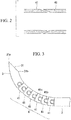
Fig. 2} Fig. 2 is a partial sectional view of a bending portion included in the puncture needle shown inFig. 1 . - {
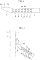
Fig. 3} Fig. 3 is a view showing a bent state of the bending portion included in the puncture needle shown inFig. 1 . - {
Fig. 4} Fig. 4 is a view showing a rigid state of the bending portion included in the puncture needle shown inFig. 1 . - {
Fig. 5} Fig. 5 is a view for explaining the operation of the puncture needle shown inFig. 1 . - {
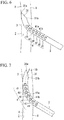
Fig. 6} Fig. 6 is a view for explaining the operation of the puncture needle shown inFig. 1 . - {
Fig. 7} Fig. 7 is a view for explaining the operation of the puncture needle shown inFig. 1 . - {
Fig. 8} Fig. 8 is a view showing the overall configuration of a modification of the puncture needle shown inFig. 1 , the modification including a supporting member. - {
Fig. 9A} Fig. 9A is a view of the overall configuration of a puncture needle in a normal state, showing a bending portion and a bending-direction control means according to a first modification. - {
Fig. 9B} Fig. 9B is a view of the overall configuration of the puncture needle in a bent state, showing the bending portion and the bending-direction control means according to the first modification. - {
Fig. 10A} Fig. 10A is a view of the overall configuration of a puncture needle in a normal state, showing a bending portion and a bending-direction control means according to a second modification. - {
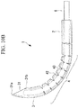
Fig. 10B} Fig. 10B is a view of the overall configuration of the puncture needle in a bent state, showing the bending portion and the bending-direction control means according to the second modification. - {
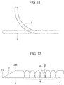
Fig. 11} Fig. 11 is a view for explaining the movement of a distal end portion of a supporting member included in the puncture needle shown inFig. 10 . - {
Fig. 12} Fig. 12 is a view showing a partial configuration of a modification of the distal end portion included in the puncture needle shown inFig. 10 . - {
Fig. 13A} Fig. 13A is a view of the overall configuration of a puncture needle in a normal state, showing a bending portion and a bending-direction control means according to a third modification. - {
Fig. 13B} Fig. 13B is a view of the overall configuration of the puncture needle in a bent state, showing the bending portion and the bending-direction control means according to the third modification. - {
Fig. 14} Fig. 14 is a view of the overall configuration of a modification of the puncture needle shown inFig. 13 , the modification including a wire. - {
Fig. 15} Fig. 15 is a view of a partial configuration of a puncture needle, showing a bending portion and a bending-direction control means according to a fourth modification. - {
Fig. 16} Fig. 16 is a view of a partial configuration of a puncture needle, showing a bending portion and a bending-direction control means according to a fifth modification. - {
Fig. 17} Fig. 17 is a view of a partial configuration of a puncture needle, showing modifications of the bending portion and the bending-direction control means shown inFig. 16 . - {
Fig. 18A} Fig. 18A is a view of a partial configuration of a puncture needle, showing a bending portion and a bending-direction control means according to a sixth modification. - {
Fig. 18B} Fig. 18B is a sectional view along the line I-I inFig. 18A , showing the bending portion and the bending-direction control means according to the sixth modification. - {
Fig. 19} Fig. 19 is a view of a partial configuration of a puncture needle, showing a bending portion and a bending-direction control means according to a seventh modification. - {
Fig. 20} Fig. 20 is a view of a partial configuration of a puncture needle, showing a modification of a blade surface. - A
puncture needle 1 according to one embodiment of the present invention will be described below with reference to the drawings. - As shown in
Fig. 1 , thepuncture needle 1 of this embodiment includes an approximately-linear elongatedmain body 2, adistal end portion 3 that is located at a distal end of themain body 2 and that is bent in an arc-like manner, and a bendingportion 4 that is provided between themain body 2 and thedistal end portion 3 to connect themain body 2 to thedistal end portion 3. - The
main body 2, thedistal end portion 3, and the bendingportion 4 are made from a metal having bioaffinity and an appropriate stiffness, such as stainless steel. Furthermore, themain body 2, thedistal end portion 3, and the bendingportion 4 form a cylindrical shape that is open at both ends, and thepuncture needle 1 has ahole 1a that leads from a base end of themain body 2 to a distal end of thedistal end portion 3 along a longitudinal central axis A (hereinafter, simply referred to as axis A) and into which a guide wire can be inserted. - The
distal end portion 3 has ablade surface 31 formed of a distal end surface that is formed inclined with respect to the axis A. Thedistal end portion 3 is bent in the same direction as theblade surface 31, ablade tip 31a of theblade surface 31 is located at an outer circumferential side of the bent shape, ablade base 31b of theblade surface 31 is located at an inner side of the bent shape, and theblade surface 31 is made to face toward an inner side of the bent shape. - The bending
portion 4 has a plurality ofcylindrical bending segments 41 that are connected to each other in the axis-A direction. Theadjacent bending segments 41 are connected to each other in a manner allowing them to swing about an axis in the direction perpendicular to the plane defined by thedistal end portion 3 when bent in one direction (in the direction perpendicular to the plane ofFig. 1 ). - Specifically, each of the bending
segments 41 has a circularaxial portion 41a that is formed so as to protrude in the axis-A direction from one end and acircular notch portion 41b that is formed at the other end and into which theaxial portion 41a of anotheradjacent bending segment 41 is fitted. Furthermore, as shown inFig. 2 , both ends of each bendingsegment 41 have shapes that allow them to radially engage with the ends of otheradjacent bending segments 41. - In a normal state, the
axial portion 41a is fitted into the inner periphery of thenotch portion 41b, with some play therebetween. By using this play, each of the bendingsegments 41 can swing about theaxial portion 41a of anotheradjacent bending segment 41. Accordingly, when an external force in a direction intersecting the axis A is applied to thedistal end portion 3, the bendingportion 4 is flexibly bent at a bending angle corresponding to this external force, as shown inFig. 3 . - On the other hand, when a pressing force in the axis-A direction is applied by bringing the
distal end portion 3 into contact with an object, theadjacent bending segments 41 are brought into close contact in the axis-A direction, thereby making the bendingportion 4 rigid in a linear manner, as shown inFig. 4 . - Note that, in the reference drawings, the
reference signs bending segment 41, in order to simplify the drawings. - Here, the distal end portion (bending-direction control means) 3 is easily brought into contact with surrounding objects, on a lateral surface thereof at an outer circumferential side of the bent shape. Accordingly, it is easy for the bending
portion 4 to curve in the same direction as the bending direction of thedistal end portion 3, i.e., in a direction in which theblade surface 31 is made to face toward an inner side of the bent shape, whereas it is difficult for the bendingportion 4 to curve in the opposite direction to the bending direction of thedistal end portion 3, i.e., in a direction in which theblade surface 31 is made to face toward an outer side of the bent shape. - Next, the operation of the thus-configured
puncture needle 1 will be described by giving an example case in which aguide wire 10 is percutaneously inserted from outside the body into a pericardial cavity X. - In order to insert the
guide wire 10 into the pericardial cavity X by using thepuncture needle 1 of this embodiment, thepuncture needle 1 is inserted into the body with theblade tip 31a facing forward and is moved forward to the vicinity of the pericardium Y while incising tissue with theblade tip 31a, as shown inFig. 5 . - While being moved forward in the tissue, the
blade tip 31a is pressed by the tissue, thus putting the bendingportion 4 into a rigid state with high stiffness (the state shown inFig. 4 ); therefore, it is possible to easily incise the tissue with theblade tip 31a. Furthermore, at this time, the positional relationship between thepuncture needle 1 and the heart Z is checked on an X-ray transparent image, for example, and thepuncture needle 1 is located so as to be inclined with respect to the surface of the heart Z while making theblade surface 31 face toward an opposite side from the heart Z. - Next, the pericardium Y is punctured by the
blade tip 31a to insert thedistal end portion 3 into the pericardial cavity X. In the pericardial cavity X, because thedistal end portion 3 is bent in such a direction as to form a convex shape with respect to the surface of the heart Z, as shown inFig. 6 , theblade tip 31a is made to point toward an opposite side from the surface of the heart Z. Here, when thedistal end portion 3 enters the pericardial cavity X, the bendingportion 4 is released from the pressing force applied by the tissue and is put into a flexible state in which it can be bent. Accordingly, in the pericardial cavity X, when the lateral surface on the outer circumferential side of thedistal end portion 3 is brought into contact with the beating heart Z, the bendingportion 4 is bent in such a direction as to move theblade surface 31 away from the heart Z, in response to the pressing force from the heart Z. - When the
puncture needle 1 is moved farther forward, the bendingportion 4 enters the pericardial cavity X while being flexibly bent, as shown inFig. 7 . Next, theguide wire 10 is inserted into thehole 1a from the base end of themain body 2, which is located outside the body, and theguide wire 10 is made to protrude from an opening in theblade surface 31. Next, while the position of theguide wire 10 is maintained, thepuncture needle 1 is pulled out toward the base end along theguide wire 10, thereby making it possible to insert theguide wire 10 into the pericardial cavity X from outside the body. - In this way, according to this embodiment, because the bending
portion 4 is passively bent in a direction in which theblade surface 31 is made to face inward, due to contact between thedistal end portion 3 and the heart Z, when thedistal end portion 3 is brought into contact with the heart Z, theblade tip 31a is moved in such a direction as to be moved away from the heart Z. Specifically, even if the puncture angle to the pericardium Y becomes relatively deep, in the pericardial cavity X, the angle of theblade surface 31 with respect to the surface of the heart Z is instantly changed to an appropriate angle, due to a change in the bending angle of the bendingportion 4. Accordingly, it is possible to reliably prevent theblade tip 31a from being brought into contact with the heart Z and also to easily perform insertion of thepuncture needle 1 into the pericardial cavity X by relaxing the accuracy of the puncture angle to the pericardium Y. - Note that, in this embodiment, in order to strengthen the stiffness of the bending
portion 4 in a rigid state, an approximately-linear supportingmember 5 that is inserted into thehole 1a when tissue is incised may be provided, as shown inFig. 8 . - By doing so, incision of the tissue by the
blade tip 31a can be performed more easily. The supportingmember 5 may be a member that has a larger flexural stiffness than the bendingportion 4, and theguide wire 10 may be used as the supportingmember 5. - Furthermore, in this embodiment, although the bending
portion 4 has a plurality of bendingsegments 41, which are connected in the axis-A direction, and the bending direction of the arc-likedistal end portion 3 sets the bending direction of the bendingportion 4, the structure of the bendingportion 4 and the bending-direction control means for setting the bending direction of the bendingportion 4 are not limited thereto. Next, modifications of thepuncture needle 1 of this embodiment that include bendingportions 4 and bending-direction control means having different structures will be described with reference toFig. 9A to Fig. 19 . - In a
puncture needle 1 according to a first modification of this embodiment, as shown inFig. 9A , a gap between twoadjacent bending segments 41 is formed wider on the same side as theblade base 31b in the circumferential direction (hereinafter, referred to as "inner circumferential side") than on the same side as theblade tip 31a in the circumferential direction (hereinafter, referred to as "outer circumferential side"). More preferably, the gap on the inner circumferential side is formed in a wedge shape whose width is gradually increased toward the radially outer side of the bendingportion 4. - According to this modification, as shown in
Fig. 9B , it is possible to further increase the maximum bending angle at which the bendingportion 4 can be bent. In this modification, because the stiffness obtained in the rigid state is lower than that of the bendingportion 4 shown inFig. 1 , additional use of the above-described supportingmember 5 is preferable at the time of tissue incision. - In a
puncture needle 1 according to a second modification of this embodiment, as shown inFig. 10A , the bendingportion 4 is formed of a flexible cylindrical member, andfirst notches 42 andsecond notches 43 that extend in the circumferential direction are formed on the inner circumferential side and the outer circumferential side of the lateral surface, as bending-direction control means. - The
second notches 43 have widths that are sufficiently narrow in the axis-A direction. On the other hand, thefirst notches 42 have widths that are sufficiently wider in the axis-A direction than those of thesecond notches 43. Accordingly, the bendingportion 4 has a higher flexural stiffness in a bending direction in which theblade surface 31 is made to face inward than in a bending direction in which theblade surface 31 is made to face outward, and, as shown inFig. 10B , the bending direction of the bendingportion 4 is set to a bending direction in which theblade surface 31 is made to face inward. Thefirst notches 42 are preferably formed in wedge shapes, like the gaps between the bendingsegments 41 of the first modification. - In this way, according to this modification, with a simple structure in which the
notches portion 4, the bending direction of the bendingportion 4 can be set. - In this modification, additional use of the supporting
member 5 is preferable in order to strengthen the stiffness of the bendingportion 4. In this modification, as shown inFig. 11 , a distal end portion of the supportingmember 5 has a bent shape in the normal state and can be elastically deformed into an approximately-linear shape, as indicated by a two-dot chain line in the figure. - When the supporting
member 5 is inserted into thehole 1a with the distal end pointing toward theblade tip 31a, as shown inFig. 10A , the distal end portion of the supportingmember 5 is straightened in thehole 1a, thus straightening the bendingportion 4. From this state, when the supportingmember 5 is rotated in thehole 1a by about 180 degrees in the circumferential direction, as shown inFig. 10B , the distal end portion of the supportingmember 5 is restored to the bent shape, thus bending the bendingportion 4. - A description will be given of how to use the supporting
member 5. At the time of tissue incision, the bendingportion 4 is formed into the straight shape shown inFig. 10A , and, in the vicinity of the pericardium Y, the bendingportion 4 is formed into the bent shape shown inFig. 10B . Accordingly, the pericardium Y can be punctured by theblade tip 31a at a smaller angle to the heart Z. After the pericardium Y is punctured by theblade tip 31a, the supportingmember 5 is pulled out from thehole 1a, and thedistal end portion 3 is moved farther forward in the pericardial cavity X, in the same way as shown inFig. 6 and Fig. 7 . - In this modification, since the difference in width between the
first notches 42 and thesecond notches 43 sets the bending direction of the bendingportion 4, thedistal end portion 3 may have a straight shape, as shown inFig. 12 . - A
puncture needle 1 according to a third modification of this embodiment is obtained by further modifying the second modification, and, as shown inFigs. 13A and13B , thesecond notches 43 are omitted. - According to this modification, it is more difficult for the bending
portion 4 to be bent in a direction in which theblade surface 31 is made to face outward, thus making it possible to more accurately set the bending direction of the bendingportion 4. Although an arc-likedistal end portion 3 is shown inFigs. 13A and13B , the straight-shapeddistal end portion 3 shown inFig. 12 may be adopted. - Furthermore, in this modification, as shown in
Fig. 14 , it is possible to provide, instead of the supportingmember 5, a wire (wire member) 6 that is located in thehole 1a along the axis-A direction, whose distal end is fixed at thedistal end portion 3, and whose base end is located at the base end of themain body 2. - By doing so, when a base end portion of the wire 6 is pulled, the bending
portion 4 can be bent at a desired timing and at a desired angle. - In a
puncture needle 1 according to a fourth modification of this embodiment, as shown inFig. 15 , the bendingportion 4 has a first portion 44 (region indicated by hatching) that is located on the inner circumferential side and asecond portion 45 that is located on the outer circumferential side, thefirst portion 44 andsecond portion 45 being made of flexible materials. Thefirst portion 44 has a higher flexibility than thesecond portion 45, thereby constituting the bending-direction control means. - In this way, by making the bending
portion 4 have different flexibilities in the circumferential direction, the flexural stiffness of the bendingportion 4 in a bending direction in which theblade surface 31 is made to face inward is made higher than the flexural stiffness thereof in a bending direction in which theblade surface 31 is made to face outward, thus making it possible to set the bending direction of the bendingportion 4. - The bending
portion 4 is fabricated by joining a plurality of members that are formed of different materials or that have different thicknesses. Alternatively, the bendingportion 4 may be configured such that the balance of materials is gradually changed in the circumferential direction, thereby gradually changing the flexibility in the circumferential direction. - In a
puncture needle 1 according to a fifth modification of this embodiment, as shown inFig. 16 , the bendingportion 4 has an elastic member (for example, coil spring) 46 whose ends are connected to thedistal end portion 3 and to themain body 2 and that is extendable/contractible in the axis-A direction and anextension restricting member 7 that restricts extension of the inner circumferential side of theelastic member 46 in the axis-A direction. InFig. 16 , theextension restricting member 7 connects, in the axis-A direction, turns of a spiral wire rod forming the coil spring, which is shown as an example of theelastic member 46, thereby restricting expansion of gaps between the turns of the wire rod in the axis-A direction. - In this way, by restricting extension of the
elastic member 46 partially in the circumferential direction, the flexural stiffness of the bendingportion 4 in a bending direction in which theblade surface 31 is made to face inward is made higher than the flexural stiffness thereof in a bending direction in which theblade surface 31 is made to face outward, thus making it possible to set the bending direction of the bendingportion 4. - In this modification, as shown in
Fig. 17 , it is possible to adopt, as theextension restricting member 7, a member made of a material that has flexibility and that does not extend in the longitudinal direction, such as a wire, one end thereof being fixed to thedistal end portion 3, and the other end thereof being fixed to themain body 2. With this configuration, the bending direction of the bendingportion 4 can also be set. - In a
puncture needle 1 according to a sixth modification of this embodiment, as shown inFigs. 18A and 18B , the bendingportion 4 is made of a flexible material and has, on the inner circumferential side, a thin-walled portion 47 whose wall thickness is thinner than that on the outer circumferential side. - In this way, by reducing the wall pressure of the
elastic member 46 partially in the circumferential direction, the flexural stiffness of the bendingportion 4 in a bending direction in which theblade surface 31 is made to face inward is made higher than the flexural stiffness thereof in a bending direction in which theblade surface 31 is made to face outward, thus making it possible to set the bending direction of the bendingportion 4. - In a
puncture needle 1 according to a seventh modification of this embodiment, as shown inFig. 19 , the bendingportion 4 hasslits 48 that are spirally formed in a region that does not include an inner-circumferential-side portion. - In this way, by providing a region in which the
slits 48 are not formed, partially in the circumferential direction, the flexural stiffness of the bendingportion 4 in a bending direction in which theblade surface 31 is made to face inward is made higher than the flexural stiffness thereof in a bending direction in which theblade surface 31 is made to face outward, thus making it possible to set the bending direction of the bendingportion 4. Furthermore, according to this modification, when theslits 48 are formed through laser processing, it is only necessary to control rotation of the bendingportion 4 in the circumferential direction, movement of laser light in the axis-A direction, and the on/off state of the laser light, thereby making is possible to facilitate the processing. - As described above, in this embodiment and the modifications thereof, the
blade surface 31, which is formed of the inclined distal end surface, is provided; however, instead of this, thedistal end portion 3 may have ablade surface 31 and ablade tip 31a that are formed over the whole circumference of the distal end, as shown inFig. 20 . - With a
puncture needle 1 having thisblade surface 31, the bendingportion 4 can be passively bent in the pericardial cavity X, thereby making it possible to prevent theblade tip 31a from being brought into contact with the heart Z. -
- 1
- puncture needle
- 1a
- hole
- 2
- main body
- 3
- distal end portion (bending-direction control means)
- 31
- blade surface
- 31a
- blade tip
- 31b
- blade base
- 4
- bending portion
- 41
- bending segment
- 41a
- axial portion
- 41b
- notch portion
- 42
- first notch (bending-direction control means)
- 43
- second notch (bending-direction control means)
- 44
- first portion (bending-direction control means)
- 45
- second portion (bending-direction control means)
- 46
- elastic member
- 47
- thin-walled portion (bending-direction control means)
- 48
- slit (bending-direction control means)
- 5
- supporting member
- 6
- wire
- 7
- extension restricting member (bending-direction control means)
- 10
- guide wire
- X
- pericardial cavity
- Y
- pericardium
- Z
- heart
Claims (12)
- A puncture needle comprising:an elongated approximately-linear main body;a distal end portion that is located at a distal end of the main body and that has a blade surface formed of a distal end surface which is formed inclined with respect to a longitudinal direction;a bending portion that is provided between the main body and the distal end portion to connect the main body to the distal end portion and that can be passively bent in response to an external force; anda bending-direction control means that sets a bending direction of the bending portion to a direction in which the blade surface is made to face toward an inner side of a bent shape.
- A puncture needle according to claim 1, wherein the bending-direction control means is configured when the distal end portion is bent in an arc-like manner with the blade surface facing toward the inner side.
- A puncture needle according to claim 1 or 2,
wherein the bending portion has a first flexural stiffness in a bending direction in which the blade surface is made to face toward the inner side and a second flexural stiffness in a bending direction in which the blade surface is made to face toward an outer side; and
the bending-direction control means is configured when the first flexural stiffness is smaller than the second flexural stiffness. - A puncture needle according to claim 3,
wherein the bending portion has notches that are formed on a lateral surface and that extend in a circumferential direction thereof; and
the notches are formed, in the circumferential direction of the bending portion, only on the same side as a blade base of the blade surface. - A puncture needle according to claim 3,
wherein the bending portion has notches that are formed on a lateral surface and that extend in a circumferential direction thereof; and
the notches are formed, in the circumferential direction of the bending portion, on the same side as a blade base of the blade surface and on the same side as a blade tip of the blade surface, and the notches that are formed on the same side as the blade base have larger widths in the longitudinal direction than the notches that are formed on the same side as the blade tip. - A puncture needle according to claim 3, wherein, in the circumferential direction of the bending portion, a side of the bending portion that is the same side as a blade base of the blade surface is made of a material having a higher flexibility than that of a side thereof that is the same side as a blade tip of the blade surface.
- A puncture needle according to claim 3, wherein the bending portion comprises:an elastic member that is extendable/contractible in the longitudinal direction of the main body; andan extension restricting member that restricts extension of the elastic member, on the same side as a blade base of the blade surface in the circumferential direction of the elastic member.
- A puncture needle according to claim 3, wherein the bending portion is formed of a cylindrical member and has a thin-walled portion having a thinner wall thickness on the same side as a blade base of the blade surface in the circumferential direction than on the same side as a blade tip of the blade surface.
- A puncture needle according to claim 3, wherein the bending portion is formed of a cylindrical member and has spiral slits formed in the circumferential direction in a region that excludes the same side of a blade base of the blade surface.
- A puncture needle according to one of claims 1 to 9,
wherein the main body, the bending portion, and the distal end portion are formed of a cylindrical member that has, therein, a hole passing therethrough in the longitudinal direction; and
the puncture needle further comprises an approximately-linear supporting member that is inserted into the hole of the main body, the bending portion, and the distal end portion, which are communicated with each other in the longitudinal direction, and that has a larger stiffness than the bending portion. - A puncture needle according to claim 10, wherein a distal end portion of the supporting member has a bent shape and can be elastically deformed into an approximately-linear shape.
- A puncture needle according to one of claims 1 to 9, further comprising a wire member whose distal end is connected to the distal end portion and that extends to the base end of the main body.
Applications Claiming Priority (2)
| Application Number | Priority Date | Filing Date | Title |
|---|---|---|---|
| JP2013080528A JP6192341B2 (en) | 2013-04-08 | 2013-04-08 | Puncture needle |
| PCT/JP2013/085098 WO2014167756A1 (en) | 2013-04-08 | 2013-12-27 | Injection needle |
Publications (2)
| Publication Number | Publication Date |
|---|---|
| EP2985048A1 true EP2985048A1 (en) | 2016-02-17 |
| EP2985048A4 EP2985048A4 (en) | 2016-10-12 |
Family
ID=51689180
Family Applications (1)
| Application Number | Title | Priority Date | Filing Date |
|---|---|---|---|
| EP13881534.5A Withdrawn EP2985048A4 (en) | 2013-04-08 | 2013-12-27 | Injection needle |
Country Status (5)
| Country | Link |
|---|---|
| US (1) | US20160022313A1 (en) |
| EP (1) | EP2985048A4 (en) |
| JP (1) | JP6192341B2 (en) |
| CN (1) | CN105120932B (en) |
| WO (1) | WO2014167756A1 (en) |
Cited By (2)
| Publication number | Priority date | Publication date | Assignee | Title |
|---|---|---|---|---|
| EP3453344A1 (en) * | 2017-08-31 | 2019-03-13 | Acclarent, Inc. | Sinuplasty guide with plurality of configurations |
| EP3650061A4 (en) * | 2017-09-08 | 2020-07-01 | Terumo Kabushiki Kaisha | PUNCTURE DEVICE |
Families Citing this family (18)
| Publication number | Priority date | Publication date | Assignee | Title |
|---|---|---|---|---|
| CN104306053A (en) * | 2014-10-22 | 2015-01-28 | 广州新诚生物科技有限公司 | Direction-controllable puncture sheath |
| CN104688296B (en) * | 2015-03-18 | 2018-02-02 | 马克 | The snakelike puncture bone cone of one kind orientation |
| WO2016152496A1 (en) * | 2015-03-23 | 2016-09-29 | メディキット株式会社 | Flexible needle for medical use |
| US10350383B2 (en) * | 2015-03-26 | 2019-07-16 | Spiration, Inc. | Variable stiffness medical device |
| JP6803691B2 (en) * | 2016-06-30 | 2020-12-23 | 株式会社ヨコオ | Flexible puncture needle and rigid mirror |
| CN110325122B (en) * | 2017-02-28 | 2024-03-19 | 波士顿科学国际有限公司 | hinge pin |
| US11547399B2 (en) * | 2017-10-16 | 2023-01-10 | Conmed Corporation | Articulating suture hook |
| CN109589159B (en) * | 2018-12-10 | 2024-05-07 | 杭州德柯医疗科技有限公司 | Puncture needle and puncture device |
| CN109589160B (en) * | 2018-12-10 | 2024-05-07 | 杭州德柯医疗科技有限公司 | Puncture needle and puncture device |
| CN109498126B (en) * | 2018-12-28 | 2020-10-27 | 北京术锐技术有限公司 | Flexible puncture needle device |
| US11357492B2 (en) * | 2019-05-20 | 2022-06-14 | Charles Cannon, Jr. | Laparoscopic intraabdominal work table retractor, instrument and positioner |
| CN114340691B (en) * | 2019-07-29 | 2024-08-09 | 尹三悦 | Biliary drainage device for retrograde percutaneous biliary drainage with negative pressure maintenance |
| JP2022553541A (en) * | 2019-10-24 | 2022-12-23 | ヤンセン バイオテツク,インコーポレーテツド | steerable needle |
| CN111297450B (en) * | 2020-03-04 | 2021-03-23 | 杭州市第三人民医院 | Uropoiesis surgery percutaneous puncture needle structure based on 3D prints |
| USD1039141S1 (en) * | 2020-04-27 | 2024-08-13 | Acclarent, Inc. | Flex section in shaft for ENT instrument |
| US20240293172A1 (en) * | 2021-03-11 | 2024-09-05 | Yokowo Co., Ltd. | Cautery puncture needle |
| EP4362823A4 (en) | 2021-07-05 | 2025-05-28 | Veinway Ltd. | VASCULAR BLOCKAGE PASSAGE |
| GB2610646B (en) * | 2021-09-14 | 2023-11-29 | I Q Endoscopes Ltd | Endoscopy system & elements thereof |
Family Cites Families (21)
| Publication number | Priority date | Publication date | Assignee | Title |
|---|---|---|---|---|
| US4759746A (en) * | 1987-05-14 | 1988-07-26 | Straus Jeffrey G | Retro-bulbar needle |
| US5306245A (en) * | 1993-02-23 | 1994-04-26 | Advanced Surgical Inc. | Articulating device |
| ES2228165T3 (en) * | 1998-12-09 | 2005-04-01 | Cook Incorporated | HOLLOW NEEDLE, CURVED, SUPERELASTIC, FOR MEDICAL USE. |
| JP4378012B2 (en) * | 2000-01-14 | 2009-12-02 | テルモ株式会社 | Puncture tool |
| JP2004208971A (en) * | 2002-12-27 | 2004-07-29 | Terumo Corp | Needle assembly |
| JP2004358016A (en) * | 2003-06-06 | 2004-12-24 | Nipro Corp | Puncture needle for easy insertion along the puncture route |
| US7320695B2 (en) * | 2003-12-31 | 2008-01-22 | Biosense Webster, Inc. | Safe septal needle and method for its use |
| DE102004002472B4 (en) * | 2004-01-16 | 2007-09-13 | Disetronic Licensing Ag | needle |
| JP4383908B2 (en) * | 2004-01-29 | 2009-12-16 | 株式会社八光 | Epidural needle |
| JP4133867B2 (en) * | 2004-02-27 | 2008-08-13 | 住友ベークライト株式会社 | Medical needle |
| US7959634B2 (en) * | 2004-03-29 | 2011-06-14 | Soteira Inc. | Orthopedic surgery access devices |
| JP4443996B2 (en) * | 2004-05-17 | 2010-03-31 | 株式会社メディカルサポート | Spinal anesthesia needle |
| JP4638276B2 (en) * | 2005-05-13 | 2011-02-23 | 株式会社八光 | Variable injection needle |
| JP4598041B2 (en) * | 2007-10-12 | 2010-12-15 | 株式会社ユニシス | Puncture needle for epidural anesthesia |
| US20090131886A1 (en) * | 2007-11-16 | 2009-05-21 | Liu Y King | Steerable vertebroplasty system |
| US20100056862A1 (en) * | 2008-09-03 | 2010-03-04 | Ethicon Endo-Surgery, Inc. | Access needle for natural orifice translumenal endoscopic surgery |
| WO2010039894A1 (en) * | 2008-09-30 | 2010-04-08 | Dfine, Inc. | System for use in treatment of vertebral fractures |
| DK2396072T3 (en) * | 2009-01-14 | 2013-04-08 | Spinal Modulation Inc | STIMULATING ELECTRODE DELIVERY SYSTEM |
| JP5448637B2 (en) * | 2009-08-18 | 2014-03-19 | 富士フイルム株式会社 | Insertion path securing device |
| JP5508804B2 (en) * | 2009-10-06 | 2014-06-04 | オリンパス株式会社 | Guide device |
| US20120265210A1 (en) * | 2011-04-15 | 2012-10-18 | Alexander Grinberg | Vertebroplasty Curved Needle |
-
2013
- 2013-04-08 JP JP2013080528A patent/JP6192341B2/en active Active
- 2013-12-27 CN CN201380075222.3A patent/CN105120932B/en not_active Expired - Fee Related
- 2013-12-27 WO PCT/JP2013/085098 patent/WO2014167756A1/en not_active Ceased
- 2013-12-27 EP EP13881534.5A patent/EP2985048A4/en not_active Withdrawn
-
2015
- 2015-10-07 US US14/877,198 patent/US20160022313A1/en not_active Abandoned
Cited By (4)
| Publication number | Priority date | Publication date | Assignee | Title |
|---|---|---|---|---|
| EP3453344A1 (en) * | 2017-08-31 | 2019-03-13 | Acclarent, Inc. | Sinuplasty guide with plurality of configurations |
| US10967159B2 (en) | 2017-08-31 | 2021-04-06 | Acclarent, Inc. | Sinuplasty guide with plurality of configurations |
| EP3650061A4 (en) * | 2017-09-08 | 2020-07-01 | Terumo Kabushiki Kaisha | PUNCTURE DEVICE |
| US11534204B2 (en) | 2017-09-08 | 2022-12-27 | Terumo Kabushiki Kaisha | Puncture apparatus |
Also Published As
| Publication number | Publication date |
|---|---|
| US20160022313A1 (en) | 2016-01-28 |
| JP6192341B2 (en) | 2017-09-06 |
| WO2014167756A1 (en) | 2014-10-16 |
| CN105120932B (en) | 2018-06-05 |
| JP2014200551A (en) | 2014-10-27 |
| EP2985048A4 (en) | 2016-10-12 |
| CN105120932A (en) | 2015-12-02 |
Similar Documents
| Publication | Publication Date | Title |
|---|---|---|
| EP2985048A1 (en) | Injection needle | |
| CN111163676B (en) | Method for manufacturing insertion tube for endoscope, and endoscope provided with insertion tube | |
| US9113783B2 (en) | Flexible tube for medical instrument and medical instrument | |
| EP1997443A2 (en) | Incision tool | |
| CN112969398B (en) | Method for manufacturing insertion tube of endoscope and endoscope having insertion tube | |
| EP3666203B1 (en) | Deflectable insertion tool | |
| CN102905632B (en) | Endoscope treatment tool | |
| EP3824936A1 (en) | Puncture needle and method of using guide wire | |
| US10039541B2 (en) | Retractor | |
| CN101416863A (en) | Endoscopic instrument and method for manufacturing thereof c | |
| US20170325829A1 (en) | Snare | |
| WO2017090196A1 (en) | Endoscope adapter, endoscope, and endoscope system | |
| KR20170112977A (en) | Medical Device | |
| CN108366872B (en) | Cannula with puncture needle | |
| JPWO2016152496A1 (en) | Medical flexible needle | |
| EP4209187B1 (en) | Dilator | |
| JP6546412B2 (en) | Guide wire | |
| WO2018229982A1 (en) | Endoscope sheath and endoscope system | |
| WO2014013564A1 (en) | Medical treatment instrument | |
| JPWO2016075740A1 (en) | Medical staples | |
| JP7709725B2 (en) | lumbar puncture needle | |
| JP2020162645A (en) | catheter | |
| JPWO2017122319A1 (en) | Surgical staples | |
| JP2018102527A (en) | Band fixing pin for use in tension band wiring method | |
| JP2012170550A (en) | Hemostatic device |
Legal Events
| Date | Code | Title | Description |
|---|---|---|---|
| PUAI | Public reference made under article 153(3) epc to a published international application that has entered the european phase |
Free format text: ORIGINAL CODE: 0009012 |
|
| 17P | Request for examination filed |
Effective date: 20151026 |
|
| AK | Designated contracting states |
Kind code of ref document: A1 Designated state(s): AL AT BE BG CH CY CZ DE DK EE ES FI FR GB GR HR HU IE IS IT LI LT LU LV MC MK MT NL NO PL PT RO RS SE SI SK SM TR |
|
| AX | Request for extension of the european patent |
Extension state: BA ME |
|
| DAX | Request for extension of the european patent (deleted) | ||
| RAP1 | Party data changed (applicant data changed or rights of an application transferred) |
Owner name: OLYMPUS CORPORATION |
|
| RAP1 | Party data changed (applicant data changed or rights of an application transferred) |
Owner name: OLYMPUS CORPORATION |
|
| A4 | Supplementary search report drawn up and despatched |
Effective date: 20160914 |
|
| RIC1 | Information provided on ipc code assigned before grant |
Ipc: A61M 5/32 20060101ALN20160908BHEP Ipc: A61B 17/00 20060101ALN20160908BHEP Ipc: A61B 17/34 20060101AFI20160908BHEP |
|
| RIN1 | Information on inventor provided before grant (corrected) |
Inventor name: YOSHIDA, KAZUHIRO |
|
| STAA | Information on the status of an ep patent application or granted ep patent |
Free format text: STATUS: REQUEST FOR EXAMINATION WAS MADE |
|
| STAA | Information on the status of an ep patent application or granted ep patent |
Free format text: STATUS: THE APPLICATION IS DEEMED TO BE WITHDRAWN |
|
| 18D | Application deemed to be withdrawn |
Effective date: 20200701 |