EP2984981A1 - Coil structure used for endoscope, and endoscope and treatment instrument each comprising said coil structure - Google Patents
Coil structure used for endoscope, and endoscope and treatment instrument each comprising said coil structure Download PDFInfo
- Publication number
- EP2984981A1 EP2984981A1 EP15785042.1A EP15785042A EP2984981A1 EP 2984981 A1 EP2984981 A1 EP 2984981A1 EP 15785042 A EP15785042 A EP 15785042A EP 2984981 A1 EP2984981 A1 EP 2984981A1
- Authority
- EP
- European Patent Office
- Prior art keywords
- endoscope
- coil tube
- curved surface
- structure used
- coil
- Prior art date
- Legal status (The legal status is an assumption and is not a legal conclusion. Google has not performed a legal analysis and makes no representation as to the accuracy of the status listed.)
- Withdrawn
Links
Images



Classifications
-
- A—HUMAN NECESSITIES
- A61—MEDICAL OR VETERINARY SCIENCE; HYGIENE
- A61M—DEVICES FOR INTRODUCING MEDIA INTO, OR ONTO, THE BODY; DEVICES FOR TRANSDUCING BODY MEDIA OR FOR TAKING MEDIA FROM THE BODY; DEVICES FOR PRODUCING OR ENDING SLEEP OR STUPOR
- A61M25/00—Catheters; Hollow probes
- A61M25/01—Introducing, guiding, advancing, emplacing or holding catheters
- A61M25/0105—Steering means as part of the catheter or advancing means; Markers for positioning
- A61M25/0133—Tip steering devices
- A61M25/0138—Tip steering devices having flexible regions as a result of weakened outer material, e.g. slots, slits, cuts, joints or coils
-
- A—HUMAN NECESSITIES
- A61—MEDICAL OR VETERINARY SCIENCE; HYGIENE
- A61B—DIAGNOSIS; SURGERY; IDENTIFICATION
- A61B1/00—Instruments for performing medical examinations of the interior of cavities or tubes of the body by visual or photographical inspection, e.g. endoscopes; Illuminating arrangements therefor
- A61B1/005—Flexible endoscopes
- A61B1/0051—Flexible endoscopes with controlled bending of insertion part
- A61B1/0057—Constructional details of force transmission elements, e.g. control wires
-
- A—HUMAN NECESSITIES
- A61—MEDICAL OR VETERINARY SCIENCE; HYGIENE
- A61B—DIAGNOSIS; SURGERY; IDENTIFICATION
- A61B1/00—Instruments for performing medical examinations of the interior of cavities or tubes of the body by visual or photographical inspection, e.g. endoscopes; Illuminating arrangements therefor
- A61B1/00064—Constructional details of the endoscope body
- A61B1/00071—Insertion part of the endoscope body
- A61B1/0008—Insertion part of the endoscope body characterised by distal tip features
- A61B1/00098—Deflecting means for inserted tools
-
- A—HUMAN NECESSITIES
- A61—MEDICAL OR VETERINARY SCIENCE; HYGIENE
- A61B—DIAGNOSIS; SURGERY; IDENTIFICATION
- A61B1/00—Instruments for performing medical examinations of the interior of cavities or tubes of the body by visual or photographical inspection, e.g. endoscopes; Illuminating arrangements therefor
- A61B1/00064—Constructional details of the endoscope body
- A61B1/0011—Manufacturing of endoscope parts
-
- A—HUMAN NECESSITIES
- A61—MEDICAL OR VETERINARY SCIENCE; HYGIENE
- A61B—DIAGNOSIS; SURGERY; IDENTIFICATION
- A61B1/00—Instruments for performing medical examinations of the interior of cavities or tubes of the body by visual or photographical inspection, e.g. endoscopes; Illuminating arrangements therefor
- A61B1/005—Flexible endoscopes
-
- A—HUMAN NECESSITIES
- A61—MEDICAL OR VETERINARY SCIENCE; HYGIENE
- A61B—DIAGNOSIS; SURGERY; IDENTIFICATION
- A61B1/00—Instruments for performing medical examinations of the interior of cavities or tubes of the body by visual or photographical inspection, e.g. endoscopes; Illuminating arrangements therefor
- A61B1/012—Instruments for performing medical examinations of the interior of cavities or tubes of the body by visual or photographical inspection, e.g. endoscopes; Illuminating arrangements therefor characterised by internal passages or accessories therefor
- A61B1/018—Instruments for performing medical examinations of the interior of cavities or tubes of the body by visual or photographical inspection, e.g. endoscopes; Illuminating arrangements therefor characterised by internal passages or accessories therefor for receiving instruments
-
- A—HUMAN NECESSITIES
- A61—MEDICAL OR VETERINARY SCIENCE; HYGIENE
- A61M—DEVICES FOR INTRODUCING MEDIA INTO, OR ONTO, THE BODY; DEVICES FOR TRANSDUCING BODY MEDIA OR FOR TAKING MEDIA FROM THE BODY; DEVICES FOR PRODUCING OR ENDING SLEEP OR STUPOR
- A61M25/00—Catheters; Hollow probes
- A61M25/01—Introducing, guiding, advancing, emplacing or holding catheters
- A61M25/09—Guide wires
-
- A—HUMAN NECESSITIES
- A61—MEDICAL OR VETERINARY SCIENCE; HYGIENE
- A61B—DIAGNOSIS; SURGERY; IDENTIFICATION
- A61B1/00—Instruments for performing medical examinations of the interior of cavities or tubes of the body by visual or photographical inspection, e.g. endoscopes; Illuminating arrangements therefor
- A61B1/005—Flexible endoscopes
- A61B1/0051—Flexible endoscopes with controlled bending of insertion part
- A61B1/0055—Constructional details of insertion parts, e.g. vertebral elements
-
- A—HUMAN NECESSITIES
- A61—MEDICAL OR VETERINARY SCIENCE; HYGIENE
- A61B—DIAGNOSIS; SURGERY; IDENTIFICATION
- A61B17/00—Surgical instruments, devices or methods
- A61B17/00234—Surgical instruments, devices or methods for minimally invasive surgery
- A61B2017/00292—Surgical instruments, devices or methods for minimally invasive surgery mounted on or guided by flexible, e.g. catheter-like, means
- A61B2017/003—Steerable
- A61B2017/00305—Constructional details of the flexible means
-
- A—HUMAN NECESSITIES
- A61—MEDICAL OR VETERINARY SCIENCE; HYGIENE
- A61B—DIAGNOSIS; SURGERY; IDENTIFICATION
- A61B17/00—Surgical instruments, devices or methods
- A61B17/00234—Surgical instruments, devices or methods for minimally invasive surgery
- A61B2017/00292—Surgical instruments, devices or methods for minimally invasive surgery mounted on or guided by flexible, e.g. catheter-like, means
- A61B2017/003—Steerable
- A61B2017/00318—Steering mechanisms
- A61B2017/00323—Cables or rods
-
- A—HUMAN NECESSITIES
- A61—MEDICAL OR VETERINARY SCIENCE; HYGIENE
- A61B—DIAGNOSIS; SURGERY; IDENTIFICATION
- A61B17/00—Surgical instruments, devices or methods
- A61B17/00234—Surgical instruments, devices or methods for minimally invasive surgery
- A61B2017/00292—Surgical instruments, devices or methods for minimally invasive surgery mounted on or guided by flexible, e.g. catheter-like, means
- A61B2017/0034—Surgical instruments, devices or methods for minimally invasive surgery mounted on or guided by flexible, e.g. catheter-like, means adapted to be inserted through a working channel of an endoscope
-
- A—HUMAN NECESSITIES
- A61—MEDICAL OR VETERINARY SCIENCE; HYGIENE
- A61M—DEVICES FOR INTRODUCING MEDIA INTO, OR ONTO, THE BODY; DEVICES FOR TRANSDUCING BODY MEDIA OR FOR TAKING MEDIA FROM THE BODY; DEVICES FOR PRODUCING OR ENDING SLEEP OR STUPOR
- A61M25/00—Catheters; Hollow probes
- A61M25/01—Introducing, guiding, advancing, emplacing or holding catheters
- A61M25/09—Guide wires
- A61M2025/09058—Basic structures of guide wires
-
- A—HUMAN NECESSITIES
- A61—MEDICAL OR VETERINARY SCIENCE; HYGIENE
- A61M—DEVICES FOR INTRODUCING MEDIA INTO, OR ONTO, THE BODY; DEVICES FOR TRANSDUCING BODY MEDIA OR FOR TAKING MEDIA FROM THE BODY; DEVICES FOR PRODUCING OR ENDING SLEEP OR STUPOR
- A61M25/00—Catheters; Hollow probes
- A61M25/0009—Making of catheters or other medical or surgical tubes
-
- A—HUMAN NECESSITIES
- A61—MEDICAL OR VETERINARY SCIENCE; HYGIENE
- A61M—DEVICES FOR INTRODUCING MEDIA INTO, OR ONTO, THE BODY; DEVICES FOR TRANSDUCING BODY MEDIA OR FOR TAKING MEDIA FROM THE BODY; DEVICES FOR PRODUCING OR ENDING SLEEP OR STUPOR
- A61M25/00—Catheters; Hollow probes
- A61M25/01—Introducing, guiding, advancing, emplacing or holding catheters
- A61M25/0105—Steering means as part of the catheter or advancing means; Markers for positioning
- A61M25/0133—Tip steering devices
- A61M25/0147—Tip steering devices with movable mechanical means, e.g. pull wires
Definitions
- the operation wire is connected to an operation lever or the like provided in an operation section for remotely operating the treatment instrument raising base and is inserted into a densely wound coil pipe in the insertion section.
- the densely wound coil pipe is provided in order to suppress shrinkage of the insertion section due to the towing of the operation wire.
- An endoscope is an endoscope in which a coil structure used in the endoscope is provided in the insertion section, the coil structure including: a coil tube, both ends of which are fixed; a wire rod densely wound to form the coil tube; a first contact surface formed on one surface of the metal wire on a distal end side of the coil tube; and a second contact surface formed on another surface of the metal wire on a proximal end side of the coil tube, the first contact surface coming into contact with the second contact surface.
- the first contact surface is formed as a convex curved surface arcuate in cross section, a curvature center of which is located further on an inner side than an outer circumferential portion of the coil tube. For the convex curved surface, a curvature radius larger than a radius of the coil tube and smaller than a curvature radius during maximum bending of the insertion section is set.
- buttons 16 such as an air/water feeding button for performing control of a delivering operation of fluid from a fluid delivering section (not shown in the figure) provided at the distal end portion 11, switches 17 such as a release switch provided at the distal end portion 11, and an operation lever 18 for raising and lowering a treatment instrument raising base 21 (see Fig. 2 ) provided at the distal end portion 11 are provided.
- the densely wound coil tube 33 is formed by winding the metal wire 40 such that, as shown in Fig. 6 , in sectional shapes, the convex curved surface 41 is located on a distal end side in the densely wound coil tube 33 and the concave curved surface 42 is located on a proximal end side in the densely wound coil tube 33.
- the curvature radiuses R1 and R2 of the arcuate shapes are set such that the respective curvature centers O1 and O2 are located within a range of a diameter D of the densely wound coil tube 33.
- both ends are fixed. Therefore, according to an increase in raising power of the treatment instrument raising base 21, a towing force of the operation wire 31 inserted through an inside increases and a compression force in an axial direction increases.
Landscapes
- Health & Medical Sciences (AREA)
- Life Sciences & Earth Sciences (AREA)
- Surgery (AREA)
- Engineering & Computer Science (AREA)
- Biomedical Technology (AREA)
- Public Health (AREA)
- Biophysics (AREA)
- Heart & Thoracic Surgery (AREA)
- Veterinary Medicine (AREA)
- Animal Behavior & Ethology (AREA)
- General Health & Medical Sciences (AREA)
- Physics & Mathematics (AREA)
- Nuclear Medicine, Radiotherapy & Molecular Imaging (AREA)
- Optics & Photonics (AREA)
- Pathology (AREA)
- Radiology & Medical Imaging (AREA)
- Medical Informatics (AREA)
- Molecular Biology (AREA)
- Hematology (AREA)
- Anesthesiology (AREA)
- Pulmonology (AREA)
- Manufacturing & Machinery (AREA)
- Endoscopes (AREA)
- Instruments For Viewing The Inside Of Hollow Bodies (AREA)
Abstract
Description
- The present invention relates to a coil structure such as a coil sheath disposed in an endoscope or a coil sheath of a treatment instrument inserted through a treatment instrument channel of the endoscope and relates to the endoscope and the treatment instrument including the coil structure.
- Conventionally, in order to observe a part where it is difficult to observe an inside of a subject such as an interior of a body of an organism or a structure, an endoscope introducible into the subject has widely been used in, for example, a medical field or an industrial field.
- For such an endoscope, for example, Japanese Patent Application Laid-Open Publication No.
5-115431 - Note that the operation wire is connected to an operation lever or the like provided in an operation section for remotely operating the treatment instrument raising base and is inserted into a densely wound coil pipe in the insertion section. The densely wound coil pipe is provided in order to suppress shrinkage of the insertion section due to the towing of the operation wire.
- However, in the endoscope provided in the past, when a sturdy treatment instrument is raised by a forceps raising base, there is a problem in that a towing force of the operation wire increases, an excessive compression force occurs in the densely wound coil pipe, and axis misalignment, buckling, and the like occur in the densely wound coil pipe.
- In particular, when a bending section is bent in a state in which the densely wound coil pipe is compressed, there is a problem in that a compression force acts in an outer circumferential direction of the densely wound coil pipe and axis misalignment, buckling, and the like easily occur in the densely wound coil pipe.
- When axis misalignment, buckling, and the like occur in the densely wound coil pipe, there is a problem in that it is likely that desired reaction is not obtained in towing and relaxing of the operation wire with respect to operation of the operation lever and the operation wire is caught and becomes inoperable.
- Therefore, the present invention has been devised in view of the circumstance described above and it is an object of the present invention to provide a coil structure used in an endoscope that can suppress occurrence of axis misalignment, buckling, and the like of a densely wound coil pipe through which an operation wire and the like are inserted and stabilize towing and relaxing operation of the operation wire and provide the endoscope and a treatment instrument including the coil structure.
- A coil structure used in an endoscope according to an aspect of the present invention includes: a coil tube disposed in or inserted into an insertion section of the endoscope, both ends of the coil tube being fixed; a wire rod densely wound to form the coil tube; a first contact surface formed on one surface of the metal wire on a distal end side of the coil tube; and a second contact surface formed on another surface of the metal wire on a proximal end side of the coil tube, the first contact surface coming into contact with the second contact surface. The first contact surface is formed as a convex curved surface arcuate in cross section, a curvature center of which is located further on an inner side than an outer circumferential portion of the coil tube. For the convex curved surface, a curvature radius larger than a radius of the coil tube and smaller than a curvature radius during maximum bending of the insertion section is set.
- An endoscope according to an aspect of the present invention is an endoscope in which a coil structure used in the endoscope is provided in the insertion section, the coil structure including: a coil tube, both ends of which are fixed; a wire rod densely wound to form the coil tube; a first contact surface formed on one surface of the metal wire on a distal end side of the coil tube; and a second contact surface formed on another surface of the metal wire on a proximal end side of the coil tube, the first contact surface coming into contact with the second contact surface. The first contact surface is formed as a convex curved surface arcuate in cross section, a curvature center of which is located further on an inner side than an outer circumferential portion of the coil tube. For the convex curved surface, a curvature radius larger than a radius of the coil tube and smaller than a curvature radius during maximum bending of the insertion section is set.
- A treatment instrument according to an aspect of the present invention is a treatment instrument in which a coil structure used in an endoscope is provided in a sheath, the coil structure including: a coil tube, both ends of which are fixed; a wire rod densely wound to form the coil tube; a first contact surface formed on one surface of the metal wire on a distal end side of the coil tube; and a second contact surface formed on another surface of the metal wire on a proximal end side of the coil tube, the first contact surface coming into contact with the second contact surface. The first contact surface is formed as a convex curved surface arcuate in cross section, a curvature center of which is located further on an inner side than an outer circumferential portion of the coil tube. For the convex curved surface, a curvature radius larger than a radius of the coil tube and smaller than a curvature radius during maximum bending of the insertion section is set.
- According to the present invention described above, it is possible to provide a coil structure used in an endoscope that can suppress occurrence of axis misalignment, buckling, and the like of a densely wound coil pipe and stabilize towing and relaxing operation of an operation wire and provide the endoscope and a treatment instrument including the coil structure.
-
-
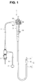
Fig. 1 is a diagram showing a configuration of an endoscope in an aspect of the present invention; -
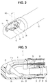
Fig. 2 is a perspective view showing a configuration of a distal end portion of an insertion section in the aspect of the present invention; -
Fig. 3 is a sectional view showing the configuration of the distal end portion of the insertion section in the aspect of the present invention; -
Fig. 4 is a perspective view showing a configuration of a densely wound coil tube through which an operation wire is inserted in the aspect of the present invention; -
Fig. 5 is a perspective view showing a configuration of a metal wire formed by the densely wound coil tube in the aspect of the present invention; -
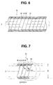
Fig. 6 is a partial sectional view showing the configuration of the densely wound coil tube through which the operation wire is inserted in the aspect of the present invention; -
Fig. 7 is a partial sectional view for describing a configuration of a convex curved surface and a concave curved surface of the densely wound coil tube in the aspect of the present invention; -
Fig. 8 is a partial sectional view for describing a state in which a compression force is generated in the densely wound coil tube in the aspect of the present invention; -
Fig. 9 is a partial sectional view of a state in which the densely wound coil tube is bent in the aspect of the present invention; -
Fig. 10 is a partial sectional view for describing a relation between a curvature radius of the densely wound coil tube and a curvature radius of the convex curved surface and the concave curved surface in the aspect of the present invention; -
Fig. 11 is a partial sectional view for describing a configuration of a convex curved surface and a concave curved surface of a densely wound coil tube in a first modification of the aspect of the present invention; -
Fig. 12 is a partial sectional view for describing a configuration of a convex curved surface and a concave curved surface of a densely wound coil tube in a second modification of the aspect of the present invention; and -
Fig. 13 is a partial sectional view for describing a configuration of a convex curved surface and a concave curved surface of a densely wound coil tube in a third modification of the aspect of the present invention. - A preferred mode of the present invention is described below with reference to the drawings. Note that, in the respective figures used in the following description, scales are varied for each of components to show the respective components in recognizable sizes on the drawings. The present invention is not limited only to numbers of the components, shapes of the components, ratios of sizes of the components, and relative positional relations among the respective components shown in the figures. In the following description, upward and downward directions viewed on a paper surface of the figures are sometimes described as an upper part and a lower part of a component.
- Note that
Fig. 1 is a diagram showing a configuration of an endoscope in an aspect of the present invention.Fig. 2 is a perspective view showing a configuration of a distal end portion of an insertion section.Fig. 3 is a sectional view showing the configuration of the distal end portion of the insertion section.Fig. 4 is a perspective view showing a configuration of a densely wound coil tube through which an operation wire is inserted.Fig. 5 is a perspective view showing a configuration of a metal wire formed by the densely wound coil tube.Fig. 6 is a partial sectional view showing the configuration of the densely wound coil tube through which the operation wire is inserted.Fig. 7 is a partial sectional view for describing a configuration of a convex curved surface and a concave curved surface of the densely wound coil tube.Fig. 8 is a partial sectional view for describing a state in which a compression force is generated in the densely wound coil tube.Fig. 9 is a partial sectional view of a state in which the densely wound coil tube is bent.Fig. 10 is a partial sectional view for describing a relation between a curvature radius of the densely wound coil tube and a curvature radius of the convex curved surface and the concave curved surface.Fig. 11 is a partial sectional view for describing a configuration of a convex curved surface and a concave curved surface of a densely wound coil tube in a first modification.Fig. 12 is a partial sectional view for describing a configuration of a convex curved surface and a concave curved surface of a densely wound coil tube in a second modification.Fig. 13 is a partial sectional view for describing a configuration of a convex curved surface and a concave curved surface of a densely wound coil tube in a third modification. - First, a schematic configuration of an
endoscope 1 in the present embodiment is described with reference toFig. 1 andFig. 2 . Note that a form is illustrated in which theendoscope 1 in the present embodiment optically observes an inside of a subject and includes a treatment instrument raising base at a distal end portion. However, a form may be adopted in which theendoscope 1 further includes an ultrasound probe at the distal end portion and scans an ultrasound beam in the subject to thereby pick up an ultrasound tomographic image of the subject. - The
endoscope 1 mainly includes aninsertion section 2 insertable into the inside of the subject, anoperation section 3 located at a proximal end of theinsertion section 2, and auniversal cord 4 extending from a side portion of theoperation section 3. - The
insertion section 2 is configured by concatenating adistal end portion 11 disposed at a distal end, abendable bending section 12 disposed on a proximal end side of thedistal end portion 11, aflexible tube section 13 having flexibility disposed on a proximal end side of thebending section 12 and connected to a distal end side of theoperation section 3. Note that theendoscope 1 may be an endoscope of a so-called rigid endoscope not including a part having flexibility in theinsertion section 2. - In the
operation section 3, besides aconduit cap 14 that communicates with a treatment instrument channel, anangle knob 15 for operating bending of thebending section 12,buttons 16 such as an air/water feeding button for performing control of a delivering operation of fluid from a fluid delivering section (not shown in the figure) provided at thedistal end portion 11,switches 17 such as a release switch provided at thedistal end portion 11, and an operation lever 18 for raising and lowering a treatment instrument raising base 21 (seeFig. 2 ) provided at thedistal end portion 11 are provided. - The treatment
instrument raising base 21 provided at thedistal end portion 11 of theinsertion section 2 raises and lowers a treatment instrument 100 (seeFig. 2 ), which projects from anopening portion 11a provided in a side circumferential portion of thedistal end portion 11, to change a projecting direction. That is, theendoscope 1 is a so-called side-view type endoscope in which anillumination window 22, anobservation window 23, and the like are provided in the side circumferential portion of thedistal end portion 11 and the treatmentinstrument raising base 21 that raises thetreatment instrument 100 in an observation direction is provided. Note that, at thedistal end portion 11, an air/water feeding nozzle 24 for, for example, mainly cleaning theobservation window 23 is provided. - At a proximal end portion of the
universal cord 4, anendoscope connector 5 connected to a not-shown light source device is provided. Illumination light emitted from the light source device is transmitted through theuniversal cord 4, and a not-shown light guide bundle inserted through theoperation section 3 and theinsertion section 2 and is emitted from an illumination window 22 (seeFig. 2 ) provided at thedistal end portion 11. Note that theendoscope 1 may include a light source such as an LED at thedistal end portion 11 as an illumination device. - A
video cable 6 is extended from theendoscope connector 5. Avideo connector 7 is provided at an end portion of thevideo cable 6. Thevideo connector 7 is electrically connected to a not-shown camera control unit. - The camera control unit is electrically connected to, via the
video connector 7, an image pickup device provided at thedistal end portion 11. The camera control unit is electrically connected to a not-shown image display device and outputs, to the not-shown image display device, an image picked up by the image pickup device from the observation window 23 (seeFig. 2 ) provided at thedistal end portion 11. - Next, a configuration of the
distal end portion 11 of theinsertion section 2 of theendoscope 1 is briefly described with reference toFig. 3 . - The
distal end portion 11 of theinsertion section 2 of theendoscope 1 includes a distal endrigid portion 25 functioning as a distal end portion main body. Adistal end cover 26 is provided to cover the distal endrigid portion 25. Arigid tube 27 functioning as a first bending piece of thebending section 12 is connected to a proximal end side of the distal endrigid portion 25. Bendingrubber 28 is provided halfway in the distal endrigid portion 25 to cover therigid tube 27. Note that the bendingrubber 28 covers theentire bending section 12. - A treatment instrument
channel connection tube 35 is fit with the distal endrigid portion 25. Atreatment instrument channel 36, which is a flexible tube body, is connected to a proximal end of the treatment instrumentchannel connection tube 35. Thetreatment instrument channel 36 is a tubular member having an inner diameter through which a treatment instrument can be inserted. Thetreatment instrument channel 36 is inserted through theinsertion section 2. A proximal end of thetreatment instrument channel 36 is connected to theconduit cap 14 of theoperation section 3. - The treatment
instrument raising base 21 is turnably axially supported by the distal endrigid portion 25 and ashaft member 21 a. Anoperation wire 31 is connected to the treatmentinstrument raising base 21. Theoperation wire 31 is towed and relaxed according to a predetermined operation input of theoperation lever 18 of theoperation section 3. The treatmentinstrument raising base 21 is thus raised and lowered. - Note that the
operation wire 31 is inserted through ametal tube 32 fit with the distal endrigid portion 25 and is further inserted through a densely woundcoil tube 33 functioning as a densely wound coil pipe shown inFig. 4 connected to a proximal end of themetal tube 32. Note that the densely woundcoil tube 33 is inserted through theinsertion section 2 and theoperation section 3. A distal end of the densely woundcoil tube 33 is fixed to themetal tube 32. A proximal end of the densely woundcoil tube 33 is fixed in theoperation section 3. - A detailed configuration of the densely wound
coil tube 33 including the coil structure used in theendoscope 1 in the present embodiment is now described below with reference toFig. 4 to Fig. 10 . - The densely wound
coil tube 33 shown inFig. 4 is a tube body formed by winding, in a spiral shape, ametal wire 40, which is an elongated wire rod having a substantially trapezoidal shape in cross section, on a side surface of which a convexcurved surface 41 and a concavecurved surface 42 are formed as shown inFig. 5 , such that the convexcurved surface 41 and the concavecurved surface 42 are in surface contact with each other. - Note that the densely wound
coil tube 33 is formed by winding themetal wire 40 such that, as shown inFig. 6 , in sectional shapes, the convexcurved surface 41 is located on a distal end side in the densely woundcoil tube 33 and the concavecurved surface 42 is located on a proximal end side in the densely woundcoil tube 33. - The convex
curved surface 41 and the concavecurved surface 42 of themetal wire 40 configure contact surfaces in the coil structure used in theendoscope 1. Note that themetal wire 40 is chamfered in an arcuate shape (an R shape) at a corner portion in a sectional direction. However, themetal wire 40 is not limited to this and may be configured to be not chamfered. - In the densely wound
coil tube 33 configured in this way, as shown inFig. 7 , the sectional shapes of the convexcurved surface 41 and the concavecurved surface 42 of the windingly formedmetal wire 40 are arcuate shapes. When curvature centers O1 and O2 of arcs of the convexcurved surface 41 and the concavecurved surface 42 are in a linear state, the curvature centers O1 and O2 are located on a center axis X. - That is, the sectional shape of the convex
curved surface 41 on a distal end side in the densely woundcoil tube 33 in the linear state is a part of an arc of an imaginary circle S1 indicated by an alternate long and short dash line of the curvature center O1 on the center axis X of the densely woundcoil tube 33. - The sectional shape of the concave
curved surface 42 on a proximal end side in the densely woundcoil tube 33 in the linear state is a part of an arc of an imaginary circle S2 indicated by an alternate long and short dash line of thecurvature center 02 on the center axis X of the densely woundcoil tube 33. - Curvature radiuses R1 and R2 of the two imaginary circles S1 and S2 are the same (R1=R2). That is, the sectional shapes of the convex
curved surface 41 and the concavecurved surface 42 are arcuate shapes having the same curvature radiuses R1 and R2. - The convex
curved surface 41 and the concavecurved surface 42 in surface contact in a front-back direction along the center axis X are formed in arcuate shapes present in the same quadrant of the two imaginary circles S1 and S2. That is, in the convexcurved surface 41 and the concavecurved surface 42, parts above the center axis X on a paper surface ofFig. 7 are arcs in a second quadrant of the imaginary circles S1 and S2 and parts below the center axis X are arcs in a third quadrant of the imaginary circles S1 and S2. - A left side on the paper surface of
Fig. 7 is the distal end side of the densely woundcoil tube 33. The densely woundcoil tube 33 is formed in an arcuate shape in which an inner diameter side of the convexcurved surface 41 projects in a distal end direction and an outer diameter side of the concavecurved surface 42 projects in a proximal end direction. - Note that, in the convex
curved surface 41 and the concavecurved surface 42, in any state of the densely woundcoil tube 33 in the linear state, the curvature radiuses R1 and R2 of the arcuate shapes are set such that the respective curvature centers O1 and O2 are located within a range of a diameter D of the densely woundcoil tube 33. - In other words, the curvature radiuses R1 and R2 of the arcs, which are the sectional shapes of the convex
curved surface 41 and the concavecurved surface 42, are set such that the respective curvature centers O1 and O2 are always located further on an internal side than an outer circumferential portion of the densely woundcoil tube 33. - Further, the respective curvature radiuses R1 and R2 of the convex
curved surface 41 and the concavecurved surface 42 are set larger than a radius (D/2) of the densely woundcoil tube 33. - In the densely wound
coil tube 33 including the coil structure used in theendoscope 1 in the present embodiment configured as described above, both ends are fixed. Therefore, according to an increase in raising power of the treatmentinstrument raising base 21, a towing force of theoperation wire 31 inserted through an inside increases and a compression force in an axial direction increases. - At this point, in the densely wound
coil tube 33, as shown inFig. 8 , since the convexcurved surface 41 and the concavecurved surface 42 are in surface contact, a force acting on the convexcurved surface 41 works in an inner circumferential direction and a force acting on the concavecurved surface 42 side works in an outer circumferential direction along tangents T1 and T2 directions of respective arcuate portions (the imaginary circles S1 and S2). That is, in the densely woundcoil tube 33, a force F1 of the convexcurved surface 41 side on the distal end side moving in the inner diameter direction and a force F2 of the concavecurved surface 42 side on the proximal end side moving in the outer diameter direction are balanced. Therefore, axis misalignment and the like are suppressed. - In the densely wound
coil tube 33, as shown inFig. 9 , the convexcurved surface 41 and the concavecurved surface 42 bend while being in surface contact along the arcuate shapes of each other according to a bending shape of thebending section 12 or theflexible tube section 13 of theinsertion section 2 of theendoscope 1. At this point, the densely woundcoil tube 33 bends in a state in which parts of the convexcurved surface 41 and the concavecurved surface 42 are always in surface contact irrespective of an inner side and an outer side of the bending. Consequently, the densely woundcoil tube 33 is bent in a state in which axis misalignment and the like are suppressed. - Note that, in the densely wound
coil tube 33, as shown inFig. 9 andFig. 10 , a curvature radius R of an arc (an imaginary circle S) in cross sections of the convexcurved surface 41 and the concavecurved surface 42 is set to be a curvature radius smaller than a curvature radius SR of bending of thebending section 12 and theflexible tube section 13 of the insertion section 2 (R<SR). - That is, in the densely wound
coil tube 33, the curvature radius R of the arc in the cross sections of the convexcurved surface 41 and the concavecurved surface 42 is set to be smaller than the curvature radius (a minimum curvature radius) SR in a state in which thebending section 12 and theflexible tube section 13 of theinsertion section 2 are bent to the maximum (R<SR). - Therefore, in a compressed state of the densely wound
coil tube 33, even if thebending section 12 or theflexible tube section 13 of theinsertion section 2 bends to the maximum and a bending angle increases, the convexcurved surface 41 and the concavecurved surface 42 are always in surface contact with each other. Therefore, sudden release of energy due to inability to withstand a compression force does not occur. Buckling and the like are also suppressed. - As described above, the densely wound
coil tube 33 including the coil structure used in theendoscope 1 in the present embodiment is configured such that, even if thesturdy treatment instrument 100 or the like is raised by the treatmentinstrument raising base 21, which is the forceps raising base, provided at thedistal end portion 11 of theendoscope 1, the towing force of theoperation wire 31 inserted through the inside increases, and an excessive compression force is generated, axis misalignment can be suppressed because the force F1 of the convexcurved surface 41 side moving in the inner diameter direction and the force F2 of the concavecurved surface 42 side on the proximal end side moving in the outer diameter direction are offset. - Further, the densely wound
coil tube 33 is configured such that, even if thebending section 12 or theflexible tube section 13 of theinsertion section 2 is bent at a large angle, since at least parts of the convexcurved surface 41 and the concavecurved surface 42 are always in surface contact, buckling and the like can also be suppressed. - As a result, in the
endoscope 1, since axis misalignment, buckling, and the like are suppressed in the densely woundcoil tube 33, a situation is prevented in which desired reaction is not obtained in towing and relaxing of theoperation wire 31 with respect to operation of theoperation lever 18 or theoperation wire 31 is caught and becomes inoperable. - In the densely wound
coil tube 33 in the present modification, as shown inFig. 11 , the convexcurved surface 41 and the concavecurved surface 42 of themetal wire 40 are set to have different curvature radiuses R1 and R2. - More specifically, in the densely wound
coil tube 33 in the linear state, the sectional shape of the convexcurved surface 41 on the distal end side is an arc of a part of the imaginary circle S1 having the curvature center O1 on the center axis X of the densely woundcoil tube 33 and the sectional shape of the concavecurved surface 42 on the proximal end side is an arc of a part of the imaginary circle S2 having the curvature center O2 on the center axis X of the densely woundcoil tube 33. - The curvature radius R1 of the imaginary circle S1 is smaller than the curvature radius R2 of the imaginary line S2 (R1<R2). That is, the sectional shape of the convex
curved surface 41 is an arcuate shape having the curvature radius R1 smaller than the curvature radius R2 of the sectional shape of the concavecurved surface 42. - Even such a configuration of the densely wound
coil tube 33 including the coil structure used in theendoscope 1 has action and effects same as those described above. Axis misalignment, buckling, and the like are suppressed in the densely woundcoil tube 33 used in theendoscope 1. - In the densely wound
coil tube 33 in the present modification, as shown inFig. 12 , the convexcurved surface 41 on the distal end side is set to have the curvature radius R1. The proximal end side does not include the concavecurved surface 42 and is formed as aplane 43 formed in a tangential direction of the arc (the imaginary circle S1), which forms the convexcurved surface 41, and having a predetermined angle θ from the distal end side to the proximal end side with respect to the center axis X. - Even such a configuration of the densely wound
coil tube 33 including the coil structure used in theendoscope 1 has action and effects same as those described above. Axis misalignment, buckling, and the like are suppressed in the densely woundcoil tube 33 used in theendoscope 1. - The densely wound
coil tube 33 in the present modification has a configuration in which, as shown inFig. 13 , both of the curvature centers 01 and 02 of the respective arcs (theimaginary circles S 1 and S2) having the curvature radiuses R1 and R2, which form the convexcurved surfaces 41 or the concavecurved surfaces 42 of themetal wire 40, are not located on the center axis X. - In this way, the densely wound
coil tube 33 has a configuration in which, in the densely woundcoil tube 33 in the linear state, if the respective curvature centers O1 and O2 of the convexcurved surfaces 41 and the concavecurved surfaces 42 of themetal wire 40 are fit further on an internal side than the outer circumferential portion within a range of the diameter D, axis misalignment, buckling, and the like are suppressed. - Note that, in
Fig. 13 , the densely woundcoil tube 33 has a configuration in which, across the center axis X of the densely woundcoil tube 33, the convexcurved surfaces 41 and the concavecurved surfaces 42 of themetal wire 40 opposed to each other in a direction orthogonal to the center axis X have arcuate shapes having the same curvature radiuses (R1 and R2; R1=R2). However, without being limited thereto, but, as long as the respective curvature centers O1 and O2 are located in a region further on the internal side than the outer circumferential portion within the range of the diameter D of the densely woundcoil tube 33, the convexcurved surfaces 41 or the concavecurved surfaces 42 opposed to each other in the direction orthogonal to the center axis X may be formed in arcuate shapes having different curvature radiuses. Further, the densely woundcoil tube 33 may have a configuration in which the curvature radiuses R1 and R2 of the convexcurved surfaces 41 and the concavecurved surfaces 42 in the front-back direction along the center axis are different (R1≠R2). - Note that, as the coil structure used in the
endoscope 1 described above, the densely woundcoil tube 33 through which theoperation wire 31 for raising and lowering the treatmentinstrument raising base 21 provided at thedistal end portion 11 of theendoscope 1 is inserted, is illustrated. However, the coil structure can also be applied to, for example, a coil tube for hardness variation for varying hardness of theinsertion section 2 of theendoscope 1 and a coil tube configuring a sheath of thetreatment instrument 100 inserted into thetreatment instrument channel 36 of theinsertion section 2 of theendoscope 1. - The coil structure used in the
endoscope 1 described above can also be applied to, for example, a coil provided in theinsertion section 2 and contracted to change the hardness of theinsertion section 2. - Further, the coil structure may be configured to insert therethrough a flexible shaft for transmitting a rotation driving force from a driving source such as a motor provided in the
operation section 3 of theendoscope 1 to some driven member provided in theinsertion section 2. Note that the coil structure itself may be used as a member for transmitting the rotation driving force. - The invention described in the respective embodiments described above is not limited to the embodiments and the modifications. Besides, in an implementation stage, various modifications can be carried out in a range not departing from the spirit of the invention. Further, inventions in various stages are included in the respective embodiments. Various inventions can be extracted according to appropriate combinations in a disclosed plurality of constituent features.
- For example, even if some of the constituent features are eliminated from the entire constituent features shown in the respective embodiments, when the described problems can be solved and the described effects can be obtained, a constitution after eliminating some of the constituent features can be extracted as an invention.
- This application is based upon and claims the benefit of priority from Japanese Patent Application No.
2014-117941
Claims (14)
- A coil structure used in an endoscope, comprising:a coil tube disposed in or inserted into an insertion section of the endoscope, both ends of the coil tube being fixed;a wire rod densely wound to form the coil tube;a first contact surface formed on one surface of the metal wire on a distal end side of the coil tube; anda second contact surface formed on another surface of the metal wire on a proximal end side of the coil tube, the first contact surface coming into contact with the second contact surface, whereinthe first contact surface is formed as a convex curved surface arcuate in cross section, a curvature center of which is located further on an inner side than an outer circumferential portion of the coil tube, andfor the convex curved surface, a curvature radius larger than a radius of the coil tube and smaller than a curvature radius during maximum bending of the insertion section is set.
- The coil structure used in the endoscope according to claim 1, wherein the second contact surface is formed as a concave curved surface arcuate in cross section, a curvature center of which is located further on the inner side than the outer circumferential portion of the coil tube.
- The coil structure used in the endoscope according to claim 2, wherein the concave curved surface has a curvature radius same as the curvature radius of the convex curved surface.
- The coil structure used in the endoscope according to claim 2, wherein the convex curved surface has the curvature radius smaller than a curvature radius of the concave curved surface.
- The coil structure used in the endoscope according to any one of claims 2 to 4, wherein the curvature centers of the convex curved surface and the concave curved surface are located on a center axis of the coil tube in a linear state.
- The coil structure used in the endoscope according to claim 1, wherein the second contact surface is a plane having a predetermined angle with respect to a center axis of the coil tube in a tangential direction of an arc in a cross section of the convex curved surface.
- The coil structure used in the endoscope according to claim 1, wherein an operation wire is inserted through an inside of the coil tube.
- The coil structure used in the endoscope according to any one of claims 1 to 7, wherein an operation wire for raising and lowering a treatment instrument raising base provided in the endoscope is inserted through the coil tube, and the coil tube is disposed in the insertion section of the endoscope.
- The coil structure used in the endoscope according to any one of claims 1 to 7, wherein the coil tube is provided in a sheath of a treatment instrument inserted into a treatment instrument channel disposed in the insertion section of the endoscope.
- The coil structure used in the endoscope according to claim 1, wherein the coil tube is disposed in the insertion section of the endoscope and contracted to change hardness of the insertion section.
- The coil structure used in the endoscope according to claim 1, wherein the coil tube is driving force transmitting means to transmit a rotational force disposed in the insertion section of the endoscope.
- The coil structure used in the endoscope according to claim 1, wherein a flexible shaft to transmit a rotational force disposed in the insertion section of the endoscope is inserted through an inside of the coil tube.
- An endoscope comprising the coil structure used in the endoscope according to any one of claims 1 to 12 in the insertion section.
- A treatment instrument comprising the coil structure used in the endoscope according to any one of claims 1 to 6 in a sheath.
Applications Claiming Priority (2)
| Application Number | Priority Date | Filing Date | Title |
|---|---|---|---|
| JP2014117941 | 2014-06-06 | ||
| PCT/JP2015/057366 WO2015186399A1 (en) | 2014-06-06 | 2015-03-12 | Coil structure used for endoscope, and endoscope and treatment instrument each comprising said coil structure |
Publications (2)
| Publication Number | Publication Date |
|---|---|
| EP2984981A1 true EP2984981A1 (en) | 2016-02-17 |
| EP2984981A4 EP2984981A4 (en) | 2017-02-08 |
Family
ID=54766480
Family Applications (1)
| Application Number | Title | Priority Date | Filing Date |
|---|---|---|---|
| EP15785042.1A Withdrawn EP2984981A4 (en) | 2014-06-06 | 2015-03-12 | Coil structure used for endoscope, and endoscope and treatment instrument each comprising said coil structure |
Country Status (5)
| Country | Link |
|---|---|
| US (1) | US9848759B2 (en) |
| EP (1) | EP2984981A4 (en) |
| JP (1) | JP5797363B1 (en) |
| CN (1) | CN105377107B (en) |
| WO (1) | WO2015186399A1 (en) |
Cited By (2)
| Publication number | Priority date | Publication date | Assignee | Title |
|---|---|---|---|---|
| EP3175772A4 (en) * | 2015-07-21 | 2018-05-16 | Olympus Corporation | Endoscope |
| WO2021091674A1 (en) * | 2019-11-06 | 2021-05-14 | Stryker Corporation | Medical devices with reinforced wires |
Families Citing this family (5)
| Publication number | Priority date | Publication date | Assignee | Title |
|---|---|---|---|---|
| CN212307786U (en) * | 2017-08-08 | 2021-01-08 | 富士胶片株式会社 | Endoscope with a detachable handle |
| US20210045720A1 (en) * | 2018-03-14 | 2021-02-18 | Hoya Corporation | Covered coil sheath for biopsy needle, biopsy needle assembly, and method of forming covered coil sheath |
| CN109540909A (en) * | 2018-12-21 | 2019-03-29 | 核动力运行研究所 | One kind being used for steam generator tube sheet outer ring corridor video check guiding device |
| CN110916601A (en) * | 2019-09-06 | 2020-03-27 | 上海澳华光电内窥镜有限公司 | Variable illumination structure and endoscope |
| CA3175119A1 (en) * | 2020-03-31 | 2021-10-07 | Edwards Lifesciences Corporation | High flexibility implant catheter with low compression |
Family Cites Families (15)
| Publication number | Priority date | Publication date | Assignee | Title |
|---|---|---|---|---|
| JPS5752448A (en) * | 1980-09-16 | 1982-03-27 | Olympus Optical Co | Guide tube for operating cable of endoscope |
| JPS5759519A (en) * | 1980-09-30 | 1982-04-09 | Olympus Optical Co | Quide tube for operating and drafting treating tool |
| JPH05115431A (en) | 1991-10-29 | 1993-05-14 | Asahi Optical Co Ltd | Treating implement raising device of endoscope and its assembling method |
| JPH06319682A (en) * | 1993-05-13 | 1994-11-22 | Olympus Optical Co Ltd | Channeled cover type endoscope system |
| US5460168A (en) * | 1992-12-25 | 1995-10-24 | Olympus Optical Co., Ltd. | Endoscope cover assembly and cover-system endoscope |
| JP3300146B2 (en) * | 1993-12-29 | 2002-07-08 | オリンパス光学工業株式会社 | Endoscope treatment instrument raising device |
| JPH08131550A (en) * | 1994-11-11 | 1996-05-28 | Nippon Zeon Co Ltd | catheter |
| US6582357B2 (en) * | 2000-05-24 | 2003-06-24 | Pentax Corporation | Treating instrument erecting device for use in endoscope |
| JP4414662B2 (en) | 2003-03-03 | 2010-02-10 | オリンパス株式会社 | Closely wound coil and medical treatment tool using the closely wound coil |
| JP4476012B2 (en) * | 2004-04-28 | 2010-06-09 | Hoya株式会社 | Endoscope treatment device raising device |
| US7579550B2 (en) * | 2006-03-31 | 2009-08-25 | Boston Scientific Scimed, Inc. | Flexible device shaft with angled spiral wrap |
| JP4497379B2 (en) * | 2006-08-23 | 2010-07-07 | 朝日インテック株式会社 | Medical treatment tool |
| JP2012231886A (en) * | 2011-04-28 | 2012-11-29 | Olympus Corp | Flexible tube part of endoscope and endoscope having the flexible tube part |
| WO2013031280A1 (en) * | 2011-09-01 | 2013-03-07 | オリンパスメディカルシステムズ株式会社 | Endsoscope |
| EP2612608B1 (en) * | 2011-09-12 | 2014-12-17 | Olympus Medical Systems Corp. | Medical coil, method of manufacturing same, and medical apparatus |
-
2015
- 2015-03-12 WO PCT/JP2015/057366 patent/WO2015186399A1/en not_active Ceased
- 2015-03-12 JP JP2015528737A patent/JP5797363B1/en not_active Expired - Fee Related
- 2015-03-12 CN CN201580000711.1A patent/CN105377107B/en not_active Expired - Fee Related
- 2015-03-12 EP EP15785042.1A patent/EP2984981A4/en not_active Withdrawn
- 2015-11-02 US US14/929,606 patent/US9848759B2/en active Active
Cited By (2)
| Publication number | Priority date | Publication date | Assignee | Title |
|---|---|---|---|---|
| EP3175772A4 (en) * | 2015-07-21 | 2018-05-16 | Olympus Corporation | Endoscope |
| WO2021091674A1 (en) * | 2019-11-06 | 2021-05-14 | Stryker Corporation | Medical devices with reinforced wires |
Also Published As
| Publication number | Publication date |
|---|---|
| CN105377107B (en) | 2017-06-16 |
| JP5797363B1 (en) | 2015-10-21 |
| CN105377107A (en) | 2016-03-02 |
| US9848759B2 (en) | 2017-12-26 |
| US20160058271A1 (en) | 2016-03-03 |
| JPWO2015186399A1 (en) | 2017-04-20 |
| WO2015186399A1 (en) | 2015-12-10 |
| EP2984981A4 (en) | 2017-02-08 |
Similar Documents
| Publication | Publication Date | Title |
|---|---|---|
| US9848759B2 (en) | Coil structure used in endoscope and endoscope and treatment instrument including coil structure | |
| KR100922916B1 (en) | Flexible tube for endoscope and endoscope device | |
| US10258223B2 (en) | Inserting instrument, rotary unit and inserting apparatus | |
| US9172227B2 (en) | Wire guide member | |
| US20160227982A1 (en) | Endoscope system | |
| JP6043027B2 (en) | Endoscope | |
| US20130331651A1 (en) | Flexible tube portion of endoscope and endoscope having this flexible tube portion | |
| EP2505117A1 (en) | Medical device with multiple curving sections | |
| US9144368B2 (en) | Endoscope | |
| EP3135182A1 (en) | Endoscope bending section and endoscope | |
| JP5351357B2 (en) | Endoscope | |
| US9872607B2 (en) | Endoscope | |
| EP3175772A1 (en) | Endoscope | |
| WO2017212748A1 (en) | Endoscope | |
| JP6271098B1 (en) | Medical overtube | |
| EP3824791A1 (en) | Endoscope auxiliary tool and endoscope | |
| US20110288375A1 (en) | Endoscope | |
| US8894565B2 (en) | Insertion device, rotating tubular member, and driving unit | |
| US20180192855A1 (en) | Insertion assist system and insertion instrument | |
| JP2014108171A (en) | Insertion device and endoscope | |
| US20160353974A1 (en) | Endoscope | |
| JP5810037B2 (en) | Endoscope system | |
| JP4504076B2 (en) | Endoscope | |
| KR101626925B1 (en) | Endoscope tube | |
| JP6223218B2 (en) | Endoscope |
Legal Events
| Date | Code | Title | Description |
|---|---|---|---|
| PUAI | Public reference made under article 153(3) epc to a published international application that has entered the european phase |
Free format text: ORIGINAL CODE: 0009012 |
|
| 17P | Request for examination filed |
Effective date: 20151105 |
|
| AK | Designated contracting states |
Kind code of ref document: A1 Designated state(s): AL AT BE BG CH CY CZ DE DK EE ES FI FR GB GR HR HU IE IS IT LI LT LU LV MC MK MT NL NO PL PT RO RS SE SI SK SM TR |
|
| AX | Request for extension of the european patent |
Extension state: BA ME |
|
| RIN1 | Information on inventor provided before grant (corrected) |
Inventor name: MIZUNO, MASAHIRO |
|
| RAP1 | Party data changed (applicant data changed or rights of an application transferred) |
Owner name: OLYMPUS CORPORATION |
|
| RAP1 | Party data changed (applicant data changed or rights of an application transferred) |
Owner name: OLYMPUS CORPORATION |
|
| RIN1 | Information on inventor provided before grant (corrected) |
Inventor name: MIZUNO, MASAHIRO |
|
| A4 | Supplementary search report drawn up and despatched |
Effective date: 20170111 |
|
| RIC1 | Information provided on ipc code assigned before grant |
Ipc: A61M 25/00 20060101ALI20170104BHEP Ipc: G02B 23/24 20060101ALI20170104BHEP Ipc: A61B 1/00 20060101AFI20170104BHEP |
|
| DAV | Request for validation of the european patent (deleted) | ||
| DAX | Request for extension of the european patent (deleted) | ||
| GRAP | Despatch of communication of intention to grant a patent |
Free format text: ORIGINAL CODE: EPIDOSNIGR1 |
|
| STAA | Information on the status of an ep patent application or granted ep patent |
Free format text: STATUS: GRANT OF PATENT IS INTENDED |
|
| INTG | Intention to grant announced |
Effective date: 20180103 |
|
| STAA | Information on the status of an ep patent application or granted ep patent |
Free format text: STATUS: THE APPLICATION IS DEEMED TO BE WITHDRAWN |
|
| 18D | Application deemed to be withdrawn |
Effective date: 20180515 |