EP2984925B1 - Free circulation box - Google Patents
Free circulation box Download PDFInfo
- Publication number
- EP2984925B1 EP2984925B1 EP15001965.1A EP15001965A EP2984925B1 EP 2984925 B1 EP2984925 B1 EP 2984925B1 EP 15001965 A EP15001965 A EP 15001965A EP 2984925 B1 EP2984925 B1 EP 2984925B1
- Authority
- EP
- European Patent Office
- Prior art keywords
- swivel
- door
- sow
- door mechanism
- crate
- Prior art date
- Legal status (The legal status is an assumption and is not a legal conclusion. Google has not performed a legal analysis and makes no representation as to the accuracy of the status listed.)
- Active
Links
- 230000007246 mechanism Effects 0.000 claims description 96
- 241001465754 Metazoa Species 0.000 claims description 13
- 241000283707 Capra Species 0.000 claims description 2
- 244000309466 calf Species 0.000 claims description 2
- 230000000384 rearing effect Effects 0.000 claims description 2
- 238000009313 farming Methods 0.000 claims 1
- 230000001012 protector Effects 0.000 claims 1
- 125000006850 spacer group Chemical group 0.000 claims 1
- 238000010276 construction Methods 0.000 description 4
- 241000283690 Bos taurus Species 0.000 description 2
- 239000000463 material Substances 0.000 description 2
- 241001494479 Pecora Species 0.000 description 1
- 241000282887 Suidae Species 0.000 description 1
- 238000006243 chemical reaction Methods 0.000 description 1
- 238000004140 cleaning Methods 0.000 description 1
- 230000001419 dependent effect Effects 0.000 description 1
- 230000000694 effects Effects 0.000 description 1
- 230000003993 interaction Effects 0.000 description 1
- 238000009329 organic farming Methods 0.000 description 1
- 238000009304 pastoral farming Methods 0.000 description 1
- 229910001220 stainless steel Inorganic materials 0.000 description 1
- 239000010935 stainless steel Substances 0.000 description 1
Images


Classifications
-
- A—HUMAN NECESSITIES
- A01—AGRICULTURE; FORESTRY; ANIMAL HUSBANDRY; HUNTING; TRAPPING; FISHING
- A01K—ANIMAL HUSBANDRY; CARE OF BIRDS, FISHES, INSECTS; FISHING; REARING OR BREEDING ANIMALS, NOT OTHERWISE PROVIDED FOR; NEW BREEDS OF ANIMALS
- A01K1/00—Housing animals; Equipment therefor
- A01K1/02—Pigsties; Dog-kennels; Rabbit-hutches or the like
- A01K1/0218—Farrowing or weaning crates
-
- A—HUMAN NECESSITIES
- A01—AGRICULTURE; FORESTRY; ANIMAL HUSBANDRY; HUNTING; TRAPPING; FISHING
- A01K—ANIMAL HUSBANDRY; CARE OF BIRDS, FISHES, INSECTS; FISHING; REARING OR BREEDING ANIMALS, NOT OTHERWISE PROVIDED FOR; NEW BREEDS OF ANIMALS
- A01K1/00—Housing animals; Equipment therefor
- A01K1/0005—Stable partitions
- A01K1/0011—Cubicle partitions
Definitions
- the invention relates to a free-range box for pigs, in particular for sows and piglets.
- These freewheel boxes often have a rectangular base, which are delimited by the usual limits and / or doors.
- the DE 2356872 A1 discloses a gate assembly for the treatment of cattle, particularly a cow.
- This arrangement has a gate frame, which is inserted into a fence gap.
- a gate is arranged on the vertical hinge of the gate frame and can thus be pivoted.
- the gate can be partially pivoted, but not by 360 °.
- the DE 74 09 700 U discloses a lattice cage for farrowing pens, with two pivotable, self-supporting side parts, which are arranged parallel to one another and between a trough. When open, this lattice cage cannot be the side wall of the farrowing pen because this functionality is missing.
- the EP 1 520 470 A2 discloses a rectangular farrowing pen with a sow cage, which has two grid-like side walls.
- the farrowing pen described has, due to its function, a rectangular base with a separate fence.
- the sow cage has an essentially trapezoidal base area, so that not the entire base area of the rectangular farrowing pen is available for the sow.
- the sow cage which has two grid-like side walls, does not make it possible in the open state for both side walls to be arranged in parallel, in order, inter alia, to achieve a desired maximum utilization of the base area.
- Freewheel boxes that meet the current requirements of animal welfare have at least a minimum footprint, for example in Germany a minimum footprint of 6 m 2 .
- the handling of the personnel that relate to the freewheel box or its parts, such as doors, should be able to be carried out using only one hand of the personnel, a so-called one-hand operation. That is, are to be moved and / or locked in particular by the personnel with one hand.
- the object of the invention is to provide a freewheel box with a swivel mechanism which meets the aforementioned requirements.
- the object of the invention is achieved by a freewheel box with a swivel mechanism with the features according to claim 1.
- Door elements 3.1 have a customary structure in this regard, for example in an open and / or closed construction.
- lattice constructions are used regularly, in particular using pipe material.
- the selected selection and arrangement in particular ensures that the door elements 3.1, also in interaction with the other parts of the free-running box, reliably protect the person from aggressive animals, the animals cannot injure themselves and the free-range animals, whether sow or piglet, on them are prevented from leaving the bay without permission.
- the door mechanism 3 has a swivel lock 3.3. This enables the sow to be securely fixed in a technically simple manner. It is also possible that the sow can be pushed off in a certain area of the base area, so that the exposed area can be cleaned by personnel, for example.
- the opening angle can be adjusted so that, for example, only the piglets or one person can enter or leave the free-range box without this also applying to the sow.
- the freewheel box comprises at least two swivel mechanisms 1.
- the previous farrowing cages can be replaced.
- the diagonal arrangement for the birth is possible.
- the longitudinal arrangement for suckling and moving the sow is possible in the free-running box. If the piglets have their full movement activity after a few days, the two swivel mechanisms 1 can be folded to the side and a free-range zone is created in the free-range pen.
- the freewheel box has two swivel mechanisms 1, there are a number of different possibilities for the design of the areas of the base area of the freewheel box that are accessible to the sow or the use of the freewheel box.
- the sow can still move in the free-running box to a limited extent. This prevents the sow from crushing piglets on the wall when it lies on the floor. This can effectively prevent the sow from squeezing the young piglets, especially when lying down ( Fig. 5 ).
- the two swivel mechanisms 1 with the door mechanism are positioned diagonally or at an angle to and on the side wall 5.1 and on the standing sow, the two door mechanisms 1 are connected to one another and the respective swivel lock 3.3 is locked, the sow is fixed diagonally in the free-running box, ie there is restricted freedom of movement. This position can be taken, for example, before and during the birth of the piglets ( Fig. 6 ).
- the object of the invention is also achieved by a freewheel box with a swivel mechanism with the features according to claim 10.
- the system of the free-running box can be used as a young animal rearing box or a young animal treatment stand for fixing calves, sheep and young goats, in conventional animal husbandry or in organic livestock farming in organic farming.
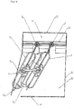
- Fig. 1 shows an embodiment of an embodiment of the pivot mechanism 1 in a side view.
- the swivel mechanism at least comprises a fastening frame 2 with a base axis 2.2 on which a bracket 2.1 is arranged, and a door mechanism 3 which has at least one door element 3.1 with an axis of rotation 3.2, this axis of rotation 3.2 being arranged parallel to the base axis 2.2 is.
- the door mechanism 3 is arranged on the mounting frame 2 so that it can pivot about the axis of rotation 3.2.
- the mounting frame 2 also has a guide arm 2.3, on which the door mechanism 3 is pivoted about the axis of rotation 3.2.
- the guide arm 2.3 has a guide opening 2.5 and the arm 2.1 has an opening 2.4 through which the axis of rotation 3.2 of the door mechanism 3 runs.
- Fig. 2 shows a possible embodiment of the door mechanism 3 in a side view.
- the door mechanism 3 has a door element 3.1 with an axis of rotation 3.2.
- a swivel lock 3.3 is arranged on the door mechanism 3, here in the form of a perforated disk 3.32 in which a locking hook 3.31 can be inserted (in Fig. 2 not shown), so that the door mechanism 3 can be locked gradually in a predetermined position.
- the door mechanism 3 has a shut-off element 3.4, which preferably consists of pipe segments 3.5, for example made of stainless steel pipe.
- a piglet guard 3.6 here as a tubular bracket, is arranged on the door mechanism 3, namely on the lower shut-off element 3.4.
- Fig. 3 shows an embodiment of an alternative embodiment of the pivot mechanism 1 in a side view.
- the swivel mechanism 1 at least comprises a fastening frame 2 with a base axis 2.2 on which a bracket 2.1 is arranged, and a door mechanism 3 which has at least one door element 3.1 with an axis of rotation 3.2 Axis of rotation 3.2 is arranged parallel to the base axis 2.2.
- the door mechanism 3 is arranged on the mounting frame 2 so as to be pivotable about the axis of rotation 3.2.
- the mounting frame 2 also has a guide arm 2.3, on which the door mechanism 3 is pivoted about the axis of rotation 3.2.
- the guide arm 2.3 has a guide opening 2.5 and the arm 2.1 has an opening 2.4 through which the axis of rotation 3.2 of the door mechanism 3 runs.
- a swivel lock 3.3 with locking hooks 3.31 is arranged on the mounting frame 2.
- the locking hook 3.31 is located in Fig. 3 not in engagement with the perforated strip 3.32, ie the door element 3.1 can be rotated about the axis of rotation 3.2, so that, for example, passage would be possible.
- Fig. 4 shows an embodiment of an embodiment of the freewheel box according to the invention with two swivel mechanisms 1 in a plan view.
- the freewheel box shown has a rectangular base, for example of 2.1 mx 2.9 m.
- the freewheel box shown has two door side walls 5.1, a rear wall 5.2 and an end wall 5.3.
- a pivot mechanism 1 is integrated in each of the door side walls 5.1, at least one of which fulfills the function of a freewheel box door.
- the piglet protection 3.6 arranged on the door mechanism 3, points in the direction of the door side wall 5.1.
- the piglet protection zone 5.4 In the area of the rear wall 5.2, preferably parallel to the rear wall 5.2, the piglet protection zone 5.4, for example with a width of 2.1 m and a length of 0.5 m, is arranged, this in the usual way by means of conventional piglet grids 5.6 to the free-running zone 5.5 is separated.
- Piglet protection zone 5.4 cannot enter the sow S or lie down there, so that the piglets in Fig. 4 not shown, are safe in this regard.
- the two mounting frames 2 are vertical and spaced from each other, for example 80 cm apart, arranged, and each attached at least to the bottom of the freewheel zone 5.5 in a conventional manner.
- Fig. 5 shows an embodiment of a further embodiment of the freewheel box according to the invention with two swivel mechanisms 1 in a plan view.
- the freewheel box shown has a rectangular base, for example of 2.1 mx 2.9 m. This base area includes in particular the piglet protection zone 5.4 and the free-range zone 5.5.
- the freewheel box shown has two door side walls 5.1, a rear wall 5.2 and an end wall 5.3, which limit the base area.
- the piglet protection zone 5.4 In the area of the rear wall 5.2, preferably parallel to the rear wall 5.2, the piglet protection zone 5.4, for example with a width of 2.1 m and a length of 0.5 m, is arranged, this in the usual way by means of conventional piglet grids 5.6 to the free-running zone 5.5 is separated.
- the piglets can pass the piglet grid 5.6, the sow S cannot.
- Piglet protection zone 5.4 cannot enter the sow S or lie down there, so that the piglets in Fig. 5 not shown, are safe in this regard.
- the two fastening frames 2 are arranged vertically and at a distance from one another, for example 80 cm, and are each fastened in the usual manner at least to the bottom of the free-running zone 5.5.
- the sow S can still move in the free-running box to a limited extent.
- the sow S is therefore not prevented from lying on the ground. This effectively prevents the risk that the sow S will squeeze the young piglets, especially when lying down ( Fig. 5 ).
- Fig. 6 shows an embodiment of a further embodiment of the freewheel box according to the invention with two swivel mechanisms 1 in a plan view.
- the freewheel box shown has a rectangular base, for example of 2.1 mx 2.9 m.
- the freewheel box shown has two door side walls 5.1, a rear wall 5.2 and an end wall 5.3.
- the piglet protection zone 5.4 In the area of the rear wall 5.2, preferably parallel to the rear wall 5.2, the piglet protection zone 5.4, for example with a width of 2.1 m and a length of 0.5 m, is arranged, this in the usual way by means of conventional piglet grids 5.6 to the free-running zone 5.5 is separated. Piglet protection zone 5.4 cannot enter the sow S or lie down there, so that the piglets are safe in this regard.
- the two fastening frames 2 are arranged vertically and at a distance from one another, for example 80 cm, and are each fastened in the usual manner at least to the bottom of the free-running zone 5.5.
- a pivotable spacing segment 3.7 can be arranged.
- Fig. 7 shows an embodiment of an alternative embodiment of the pivot mechanism 1 in a perspective side view.
- the swivel mechanism at least comprises a mounting frame 2 with a base axis 2.2 on which a bracket 2.1 is arranged, and a door mechanism 3 which has at least one door element 3.1 with an axis of rotation 3.2, this axis of rotation 3.2 being arranged parallel to the base axis 2.2.
- the door mechanism 3 is arranged on the mounting frame 2 so as to be pivotable about the axis of rotation 3.2.
- a ratchet lock 6 is used for the gradual locking. This has a ring gear 6.1 through which the base axis 2.2 runs and a ring gear 6.2 through which the axis of rotation 3.2 runs. A connecting rod 6.3 is arranged between the ring gear 6.1 and the ring gear 6.2. A ratchet mechanism 6.3 is arranged at each of the two ends of the connecting rod 6.4.
Description
Die Erfindung betrifft eine Freilaufbox für Schweine, insbesondere für Sauen und Ferkel. Diese Freilaufboxen besitzen oft eine rechteckige Grundfläche, wobei diese durch diesbezüglich übliche Begrenzungen und/oder Türen abgegrenzt sind.The invention relates to a free-range box for pigs, in particular for sows and piglets. These freewheel boxes often have a rectangular base, which are delimited by the usual limits and / or doors.
Die
Die
Die
Freilaufboxen, welchen den derzeitigen Anforderungen des Tierwohls entsprechen, besitzen zumindest eine Mindestgrundfläche, beispielsweise in Deutschland eine Mindestgrundfläche von 6 m2.Freewheel boxes that meet the current requirements of animal welfare have at least a minimum footprint, for example in Germany a minimum footprint of 6 m 2 .
Außerdem wird diesbezüglich angestrebt, die Sauen nur so wenig wie möglich in ihrer Bewegungsfreiheit, insbesondere in räumlicher und/oder zeitlicher Hinsicht, beispielsweise während der Geburt der Ferkel, den ersten Tagen nach der Geburt der Ferkel, zum Zwecke der Reinigung oder des Zuganges des Tierarztes, einzuschränken. Dem Tierarzt muss beispielsweise ermöglicht sein, die Sau kurzfristig für eine Untersuchung oder Behandlung zu arretieren.In this regard, efforts are also being made to ensure that the sows have as little freedom of movement as possible, particularly in terms of space and / or time, for example during the birth of the piglets, the first days after the birth of the piglets, for the purpose of cleaning or for access by the veterinarian. For example, the veterinarian must be able to arrest the sow at short notice for an examination or treatment.
Diese Begrenzungen und/oder Türen der Freilaufboxen müssen der Art gestaltet und dimensioniert sein, dass Personen vor aggressiven Tieren sicher geschützt sind, die Tiere sich nicht verletzen und die freilaufenden Tiere, ob Sau oder Ferkel, daran gehindert sind, die Bucht unerlaubt zu verlassen.These limits and / or doors of the free-range boxes must be designed and dimensioned in such a way that people are protected from aggressive animals, the animals do not get injured and the free-range animals, whether sow or piglet, are prevented from leaving the bay without permission.
Die Handhabungen des Personals die die Freilaufbox bzw. deren Teile, wie Türen, betreffen, sollen unter Nutzung nur einer Hand des Personals, einer sogenannte Einhandbedienung, erfolgen können. D. h. insbesondere vom Personal mit einer Hand zu bewegen und/oder zu arretieren sind.The handling of the personnel that relate to the freewheel box or its parts, such as doors, should be able to be carried out using only one hand of the personnel, a so-called one-hand operation. That is, are to be moved and / or locked in particular by the personnel with one hand.
Eine solche Freilaufbox ist bisher aus dem Stand der Technik nicht bekannt; wird jedoch dringend benötigt.Such a freewheel box is not yet known from the prior art; is urgently needed, however.
Aufgabe der Erfindung ist es, eine Freilaufbox mit Schwenkmechanismus bereitzustellen, welche vorgenannten Anforderungen erfüllt.The object of the invention is to provide a freewheel box with a swivel mechanism which meets the aforementioned requirements.
Die Aufgabe der Erfindung wird durch eine Freilaufbox mit Schwenkmechanismus mit den Merkmalen gemäß Anspruch 1 gelöst.The object of the invention is achieved by a freewheel box with a swivel mechanism with the features according to
Erfindungswesentlich ist, dass
sich zumindest drei verschiedene Gestaltungen der für die Sau (S) zugänglichen Bereiche der Grundfläche der Freilaufbox ergeben:
- sind die beiden Schwenkmechanismen (1) mit dem Türmechanismus (3) parallel zur und an der Seitenwand (5.1) positioniert und die jeweiligen Schwenkarretierung (3.3) arretiert, kann die Sau (S) sich unbeschränkt in der Freilaufbox bewegen und die Freilaufbox ist in sich geschlossen, aber offen für die Sau (S),
- sind die beiden Schwenkmechanismen (1) mit dem Türmechanismus (3) parallel zur und an der stehenden Sau (S) positioniert, die beiden Türmechanismen (3) miteinander verbunden und die jeweiligen Schwenkarretierung (3.3) nicht arretiert, kann die Sau (S) sich in der Freilaufbox dennoch beschränkt bewegen kann,
there are at least three different designs of the areas of the base of the free-running box accessible to the sow (S):
- If the two swivel mechanisms (1) with the door mechanism (3) are positioned parallel to and on the side wall (5.1) and the respective swivel lock (3.3) is locked, the sow (S) can move freely in the Move the freewheel box and the freewheel box is self-contained, but open to the sow (S),
- If the two swivel mechanisms (1) with the door mechanism (3) are positioned parallel to and on the standing sow (S), the two door mechanisms (3) are connected to each other and the respective swivel lock (3.3) is not locked, the sow (S) can move can still move in the freewheel box with restrictions,
Die Dimensionierung der Teile des Schwenkmechanismus und die Auswahl der eingesetzten Materialien erfolgt in üblicher Art und Weise unter Berücksichtigung der jeweiligen Erfordernisse, beispielsweise der jeweiligen Grundfläche der Freilaufbox. Türelemente 3.1 besitzen einen diesbezüglich üblichen Aufbau, beispielsweise in offener und/oder geschlossener Bauweise.The dimensions of the parts of the swivel mechanism and the selection of the materials used are carried out in the usual manner, taking into account the respective requirements, for example the respective base area of the freewheel box. Door elements 3.1 have a customary structure in this regard, for example in an open and / or closed construction.
Bei offener Bauweise kommen regelmäßig Gitterkonstruktionen, insbesondere unter Verwendung von Rohrmaterial, zum Einsatz.In the case of an open construction, lattice constructions are used regularly, in particular using pipe material.
Durch die gewählte Auswahl und Anordnung wird insbesondere erreicht, dass die Türelemente 3.1, auch im Zusammenspiel mit den anderen Teilen der Freilaufbox, das Personen vor aggressiven Tieren sicher geschützt, die Tiere sich nicht verletzen können und die freilaufenden Tiere, ob Sau oder Ferkel, daran gehindert sind, die Bucht unerlaubt zu verlassen.The selected selection and arrangement in particular ensures that the door elements 3.1, also in interaction with the other parts of the free-running box, reliably protect the person from aggressive animals, the animals cannot injure themselves and the free-range animals, whether sow or piglet, on them are prevented from leaving the bay without permission.
Die abhängigen Ansprüche 2 bis 9 enthalten vorteilhafte Ausgestaltungen der Erfindung ohne diese damit zu begrenzen.The dependent claims 2 to 9 contain advantageous embodiments of the invention without thereby limiting it.
Bevorzugt ist, dass der Türmechanismus 3 eine Schwenkarretierung 3.3 besitzt. Damit ist ermöglicht, dass in technisch einfacher Art und Weise die Sau sicher fixiert werden kann. Außerdem ist ermöglicht, dass die Sau in einem bestimmten Bereich der Grundfläche abdrängbar ist, so dass der freigelegte Bereich beispielsweise vom Personal gereinigt werden kann.It is preferred that the
Wird der Schwenkmechanismus in seiner Tor-Funktion genutzt, kann der Öffnungswinkel eingestellt werden, so dass beispielsweise nur die Ferkel oder eine Person die Freilaufbox betreten oder verlassen können, ohne dass dies für die Sau auch gilt.If the swivel mechanism is used in its gate function, the opening angle can be adjusted so that, for example, only the piglets or one person can enter or leave the free-range box without this also applying to the sow.
Bevorzugt ist, dass die Freilaufbox zumindest zwei Schwenkmechanismen 1 umfasst. Durch den Einsatz von zwei Schwenkmechanismen 1 können die bisherigen Abferkelkäfige ersetzt werden. Außerdem ist die Diagonalaufstellung für die Geburt ermöglicht Nach der Geburt ist die Längsaufstellung für das Säugen und Bewegen der Sau in der Freilaufbox ermöglicht. Besitzen die Ferkel nach einigen Tagen ihre volle Bewegungsaktivität können die zwei Schwenkmechanismen 1 an die Seite geklappt werden und es entsteht eine Freilaufzone in der Freilaufbucht.It is preferred that the freewheel box comprises at least two
Dies ist alles ohne aufwendigen Umbau und mit derselben technischen Grundausrüstung der Freilaufbox möglich, wobei die notwendigen Positionswechsel der Schwenkmechanismen 1 und deren Teile grundsätzlich im Einhandmodus realisiert werden können.This is all possible without expensive conversion and with the same basic technical equipment of the freewheel box, whereby the necessary changes in position of the
Besitzt die Freilaufbox zwei Schwenkmechanismen 1 ergeben sich eine Reihe von unterschiedlichen Möglichkeiten für die Gestaltung der für die Sau zugänglichen Bereiche der Grundfläche der Freilaufbox bzw. der Nutzung der Freilaufbox.If the freewheel box has two
Sind die beiden Schwenkmechanismen 1 mit dem Türmechanismus parallel zur und an der Seitenwand 5.1 positioniert und die jeweiligen Schwenkarretierung 3.3 arretiert kann die Sau sich unbeschränkt in der Freilaufbox bewegen und die Freilaufbox ist in sich geschlossen, aber offen für die Sau (
Sind die beiden Schwenkmechanismen 1 mit dem Türmechanismus parallel zur und an der stehenden Sau positioniert, die beiden Türmechanismen 1 miteinander verbunden und die jeweiligen Schwenkarretierung 3.3 nicht arretiert, kann die Sau sich in der Freilaufbox dennoch beschränkt bewegen. Die Sau ist somit gehindert, Ferkel an der Wand zu erdrücken, wenn sie sich auf den Boden legt. Damit kann die Gefahr, dass die Sau die jungen Ferkel, insbesondere beim Hinlegen drückt, wirkungsvoll gebannt werden (
Sind die beiden Schwenkmechanismen 1 mit dem Türmechanismus diagonal bzw. angewinkelt zur und an der Seitenwand 5.1 und an der stehenden Sau positioniert, die beiden Türmechanismen 1 miteinander verbunden und die jeweiligen Schwenkarretierung 3.3 arretiert, steht die Sau diagonal fixiert in der Freilaufbox, d.h. es besteht eingeschränkte Bewegungsfreiheit. Diese Position kann beispielsweise vor und während der Geburt der Ferkel eingenommen werden (
Die Aufgabe der Erfindung wird außerdem durch eine Freilaufbox mit Schwenkmechanismus mit den Merkmalen gemäß Anspruch 10 gelöst. Erfindungsgemäß kann das System der Freilaufbox als Jungtieraufzuchtbox oder Jungtierbehandlungsstand zur Fixierung von Kälbern, Schafen und junge Ziegen, in der konventionellen Tierhaltung oder der ökologischen Nutztierhaltung im Öko-Landbau eingesetzt werden.The object of the invention is also achieved by a freewheel box with a swivel mechanism with the features according to claim 10. According to the invention, the system of the free-running box can be used as a young animal rearing box or a young animal treatment stand for fixing calves, sheep and young goats, in conventional animal husbandry or in organic livestock farming in organic farming.
Weitere Merkmale, Eigenschaften und Vorteile der vorliegenden Erfindung ergeben sich aus der nachfolgenden Beschreibung von Ausführungsbeispielen unter Bezugnahme auf die
Es zeigen:
- Fig. 1
- ein Ausführungsbeispiel eine Ausführungsform des Schwenkmechanismus in einer Seitenansicht,
- Fig. 2
- eine Ausführungsform des
Türmechanismus 3 in einer Seitenansicht, - Fig. 3
- ein Ausführungsbeispiel eine weitere Ausführungsform des Schwenkmechanismus in einer Seitenansicht als Türelement,
- Fig. 4
- ein Ausführungsbeispiel einer Ausführungsform der erfindungsgemäßen Freilaufbox
mit zwei Schwenkmechanismen 1 in einer Draufsicht als geöffnete Freilaufbox, - Fig. 5
- ein Ausführungsbeispiel einer weiteren Ausführungsform der erfindungsgemäßen Freilaufbox
mit zwei Schwenkmechanismen 1 in einer Draufsicht, als parallel bewegliche Freilaufbox, - Fig. 6
- ein Ausführungsbeispiel einer weiteren Ausführungsform der erfindungsgemäßen Freilaufbox
mit zwei Schwenkmechanismen 1 in einer Draufsicht als Diagonalbox geführt und - Fig. 7
- ein Ausführungsbeispiel einer alternativen Ausführungsform des
Schwenkmechanismus 1 in einer perspektivischen Seitenansicht.
- Fig. 1
- an embodiment of an embodiment of the pivot mechanism in a side view,
- Fig. 2
- an embodiment of the
door mechanism 3 in a side view, - Fig. 3
- an embodiment of another embodiment of the pivot mechanism in a side view as a door element,
- Fig. 4
- An embodiment of an embodiment of the freewheel box according to the invention with two
swivel mechanisms 1 in a plan view as an open freewheel box, - Fig. 5
- 1 shows an exemplary embodiment of a further embodiment of the freewheel box according to the invention with two
swivel mechanisms 1 in a plan view, as a freewheel box which can be moved in parallel, - Fig. 6
- an embodiment of a further embodiment of the freewheel box according to the invention with two
swivel mechanisms 1 in a top view as a diagonal box and - Fig. 7
- an embodiment of an alternative embodiment of the
pivot mechanism 1 in a perspective side view.
Der Befestigungsrahmen 2 besitzt außerdem einen Führungsausleger 2.3, an welchem der Türmechanismus 3 schwenkbar über die Drehachse 3.2 an gelenkt ist.The mounting
Der Führungsausleger 2.3 besitzt eine Führungsöffnung 2.5 und der Ausleger 2.1 besitzt eine Öffnung 2.4, durch welche die Drehachse 3.2 des Türmechanismus 3 jeweils verläuft.The guide arm 2.3 has a guide opening 2.5 and the arm 2.1 has an opening 2.4 through which the axis of rotation 3.2 of the
Alternativ können auch andere Arretierungen, welche das Verschwenken des Türmechanismus 3 in Bezug zum Befestigungsrahmen 2 bei Bedarf verhindert. Diese Arretierungen, analog der Schwenkarretierung 3, können in üblicher Art und Weise ausgewählt und stufenlos oder stufenweise funktionsbedingt agieren.Alternatively, other detents, which prevent the pivoting of the
Der Türmechanismus 3 besitzt ein Absperrelement 3.4, welches bevorzugt aus Rohrsegmenten 3.5, beispielsweise aus Edelstahlrohr, bestehend.The
Am Türmechanismus 3, nämlich am unteren Absperrelement 3.4, ist ein Ferkelschutz 3.6, hier als Rohrbügel, angeordnet.A piglet guard 3.6, here as a tubular bracket, is arranged on the
Der Schwenkmechanismus 1 zumindest umfasst einen Befestigungsrahmen 2 mit einer Basisachse 2.2 an welcher ein Ausleger 2.1 angeordnet ist, und ein Türmechanismus 3, welcher zumindest ein Türelement 3.1 mit einer Drehachse 3.2 besitzt, wobei diese Drehachse 3.2 parallel zur Basisachse 2.2 angeordnet ist. Der Türmechanismus 3 ist über die Drehachse 3.2 schwenkbar am Befestigungsrahmen 2 angeordnet.The
Der Befestigungsrahmen 2 besitzt außerdem einen Führungsausleger 2.3, an welchem der Türmechanismus 3 schwenkbar über die Drehachse 3.2 an gelenkt ist.The mounting
Der Führungsausleger 2.3 besitzt eine Führüngsöffnung 2.5 und der Ausleger 2.1 besitzt eine Öffnung 2.4, durch welche die Drehachse 3.2 des Türmechanismus 3 jeweils verläuft.The guide arm 2.3 has a guide opening 2.5 and the arm 2.1 has an opening 2.4 through which the axis of rotation 3.2 of the
Am Befestigungsrahmen 2 ist eine Schwenkarretierung 3.3 mit Arretierungshaken 3.31 angeordnet.A swivel lock 3.3 with locking hooks 3.31 is arranged on the mounting
Der Arretierungshaken 3.31 befindet sich in
Die dargestellte Freilaufbox besitzt eine rechteckige Grundfläche, beispielsweise von 2,1 m x 2,9m.The freewheel box shown has a rectangular base, for example of 2.1 mx 2.9 m.
Die dargestellte Freilaufbox besitzt zwei Türseitenwände 5.1, eine Rückwand 5.2 und eine Stirnwand 5.3.The freewheel box shown has two door side walls 5.1, a rear wall 5.2 and an end wall 5.3.
In die Türseitenwand 5.1 ist jeweils ein Schwenkmechanismen 1 integriert, wobei zumindest einer dieser die Funktion einer Freilaufboxtür erfüllt. Der Ferkelschutz 3.6, angeordnet am Türmechanismus 3, zeigt jeweils in Richtung der Türseitenwand 5.1. Im Bereich der Rückwand 5.2, bevorzugt parallel zur Rückwand 5.2, ist die Ferkelschutzzone 5.4, beispielsweise mit einer Breite von 2,1 m und einer Länge von 0,5m, angeordnet, wobei diese durch übliche Ferkelgitter 5.6 zur Freilaufzone 5.5 in üblicher Art und Weise abgetrennt ist. Die Ferkelschutzzone 5.4 kann die Sau S nicht betreten bzw. sich dort nicht hinlegen, so dass die Ferkel, in
Im Bereich der Ferkelgitter 5.6 sind die beiden Befestigungsrahmen 2 senkrecht und voneinander beabstandet, beispielsweise 80 cm beanstandet, angeordnet, und jeweils zumindest am Boden der Freilaufzone 5.5 in üblicher Art und Weise befestigt.In the area of the piglet grid 5.6, the two mounting
Dabei sind die beiden Schwenkmechanismen 1 mit dem Türmechanismus 3 in
Die dargestellte Freilaufbox besitzt zwei Türseitenwände 5.1, eine Rückwand 5.2 und eine Stirnwand 5.3, welche die Grundfläche begrenzen.The freewheel box shown has two door side walls 5.1, a rear wall 5.2 and an end wall 5.3, which limit the base area.
Im Bereich der Rückwand 5.2, bevorzugt parallel zur Rückwand 5.2, ist die Ferkelschutzzone 5.4, beispielsweise mit einer Breite von 2,1 m und einer Länge von 0,5m, angeordnet, wobei diese durch übliche Ferkelgitter 5.6 zur Freilaufzone 5.5 in üblicher Art und Weise abgetrennt ist. Die Ferkel können das Ferkelgitter 5.6 passieren, die Sau S nicht. Die Ferkelschutzzone 5.4 kann die Sau S nicht betreten bzw. sich dort nicht hinlegen, so dass die Ferkel, in
Im Bereich der Ferkelgitter 5.6 sind die beiden Befestigungsrahmen 2 senkrecht und von einander beabstandet, beispielsweise 80 cm beabstandet, angeordnet, und jeweils zumindest am Boden der Freilaufzone 5.5 in üblicher Art und Weise befestigt.In the area of the piglet grids 5.6, the two
Sind die beiden Schwenkmechanismen 1 mit dem Türmechanismus 3 parallel zur und an der stehenden Sau S positioniert, die beiden Türmechanismen 3 miteinander durch zwei Verbindungselemente 4 verbunden und die jeweiligen Schwenkarretierung 3.3 nicht arretiert, kann die Sau S sich in der Freilaufbox dennoch beschränkt bewegen. Die Sau S ist somit nicht gehindert, sich auf den Boden zu legen. Damit kann die Gefahr, dass die Sau S die jungen Ferkel, insbesondere beim Hinlegen drückt, wirkungsvoll gebannt werden(
Damit ist erstmals ermöglicht, dass die Sau S, eingesperrt zwischen den beiden Schwenkmechanismen 1, sich, insbesondere wie mit einem Parallelogramm, durch die Freilaufbox bewegen kann. Sozusagen ein "freilaufender" Kastenstand, der sich mit der Sau S mitbewegt.This makes it possible for the first time that the sow S, trapped between the two
Die dargestellte Freilaufbox besitzt zwei Türseitenwände 5.1, eine Rückwand 5.2 und eine Stirnwand 5.3.The freewheel box shown has two door side walls 5.1, a rear wall 5.2 and an end wall 5.3.
Im Bereich der Rückwand 5.2, bevorzugt parallel zur Rückwand 5.2, ist die Ferkelschutzzone 5.4, beispielsweise mit einer Breite von 2,1 m und einer Länge von 0,5m, angeordnet, wobei diese durch übliche Ferkelgitter 5.6 zur Freilaufzone 5.5 in üblicher Art und Weise abgetrennt ist. Die Ferkelschutzzone 5.4 kann die Sau S nicht betreten bzw. sich dort nicht hinlegen, so dass die Ferkel diesbezüglich sicher sind.In the area of the rear wall 5.2, preferably parallel to the rear wall 5.2, the piglet protection zone 5.4, for example with a width of 2.1 m and a length of 0.5 m, is arranged, this in the usual way by means of conventional piglet grids 5.6 to the free-running zone 5.5 is separated. Piglet protection zone 5.4 cannot enter the sow S or lie down there, so that the piglets are safe in this regard.
Im Bereich der Ferkelgitter 5.6 sind die beiden Befestigungsrahmen 2 senkrecht und von einander beabstandet, beispielsweise 80 cm beabstandet, angeordnet, und jeweils zumindest am Boden der Freilaufzone 5.5 in üblicher Art und Weise befestigt.In the area of the piglet grids 5.6, the two
Sind die beiden Schwenkmechanismen 1 mit dem Türmechanismus 3 diagonal bzw. angewinkelt zur und an der einen Seitenwand 5.1 und an der stehenden Sau S positioniert, die beiden Türmechanismen 3 miteinander durch ein Verbindungselement 4 verbunden und die jeweiligen Schwenkarretierung 3.3 arretiert, steht die Sau S fixiert in der Freilaufbox, d.h. es besteht keine Bewegungsfreiheit. Diese Position kann beispielsweise vor und während der Geburt der Ferkel eingenommen werden.Are the two
Um hinter der Sau S einen ausreichenden Freiraum, insbesondere während der Geburt zu haben, kann ein verschwenkbares Abstandssegment 3.7 angeordnet sein.In order to have sufficient space behind the sow S, in particular during birth, a pivotable spacing segment 3.7 can be arranged.
Der Schwenkmechanismus zumindest umfasst einen Befestigungsrahmen 2 mit einer Basisachse 2.2 an welcher ein Ausleger 2.1 angeordnet ist, und ein Türmechanismus 3, welcher zumindest ein Türelement 3.1 mit einer Drehachse 3.2 besitzt, wobei diese Drehachse 3.2 parallel zur Basisachse 2.2 angeordnet ist. Der Türmechanismus 3 ist über die Drehachse 3.2 schwenkbar am Befestigungsrahmen 2 angeordnet.The swivel mechanism at least comprises a mounting
Zur stufenweisen Arretierung wird eine Ratschenarretierung 6 verwendet. Diese besitzt einen Zahnkranz 6.1, durch welchen die Basisachse 2.2 verläuft, und einen Zahnkranz 6.2, durch welchen die Drehachse 3.2 verläuft. Zwischen dem Zahnkranz 6.1 und dem Zahnkranz 6.2 ist eine Verbindungsstange 6.3 angeordnet. An den beiden Enden der Verbindungsstange 6.4 ist jeweils ein Ratschenmechanismus 6.3 angeordnet.A ratchet lock 6 is used for the gradual locking. This has a ring gear 6.1 through which the base axis 2.2 runs and a ring gear 6.2 through which the axis of rotation 3.2 runs. A connecting rod 6.3 is arranged between the ring gear 6.1 and the ring gear 6.2. A ratchet mechanism 6.3 is arranged at each of the two ends of the connecting rod 6.4.
- 11
- Schwenkmechanismusswivel mechanism
- 22
- Befestigungsrahmenmounting frame
- 2.12.1
- Auslegerboom
- 2.22.2
- Basisachsebase axis
- 2.32.3
- Führungsauslegeridler arms
- 2.42.4
- Öffnungopening
- 2.52.5
- Führungsöffnungguide opening
- 33
- Türmechanismusdoor mechanism
- 3.13.1
- Türelementdoor element
- 3.23.2
- Drehachseaxis of rotation
- 3.33.3
- Schwenkarretierungswivel lock
- 3.313.31
- Arretierungshakenlocking hooks
- 3.323:32
- Lochscheibeperforated disc
- 3.43.4
- Absperrelementshut-off
- 3.53.5
- Rohrsegmentenpipe segments
- 3.63.6
- Ferkelschutzfarrowing
- 3.73.7
- Abstandssegmentdistance segment
- 44
- Verbindungselementconnecting element
- 55
- GrundflächeFloor space
- 5.15.1
- TürseitenwandDoor sidewall
- 5.25.2
- Rückwandrear wall
- 5.35.3
- Stirnwandbulkhead
- 5.45.4
- FerkelschutzzonePiglet protection zone
- 5.55.5
- FreilaufzoneFree zone
- 5.65.6
- Ferkelgitterpiglet grid
- 6.6th
- RatschenarretierungRatschenarretierung
- 6.16.1
- Zahnkranzsprocket
- 6.26.2
- Zahnkranzsprocket
- 6.36.3
- Ratschenmechanismusratchet mechanism
- 6.46.4
- Verbindungsstangeconnecting rod
- SS
- Sausow
Claims (10)
- Free roaming crate comprising at least two door side walls (5.1), one rear wall (5.2), one front wall (5.3), and two swivel mechanisms (1), whereby each of these swivel mechanisms (1) comprises at least one mounting frame (2) with a base axis (2.2), on which at least one arm (2.1) is arranged, and one door mechanism (3), which has at least one door element (3.1) with an axis of rotation (3.2), whereby this axis of rotation (3.2) is arranged parallel to the base axis (2.2), and the door mechanism (3) is arranged for swivel-mounting on the mounting frame (2) and the door mechanism (3) has a swivel lock (3.3), which enables the door element (3.1) to be locked in different positions, whereby at least three different variations of the floor area of the free roaming crate accessible by the sow (S) result:- when the two swivel mechanisms (1) with the door mechanism (3) are positioned parallel to and on the side wall (5.1) and lock the particular swivel lock (3.3), the sow (S) is able to move freely without restriction in the free roaming crate, and the free roaming crate is closed to the outside, but open on the Inside for the sow (S),- when the two swivel mechanisms (1) with the door mechanism (3) are positioned parallel to and on the standing sow (S), the two door mechanisms (3) are connected to each other, and the particular swivel lock (3.3) is not locked, the sow (S) nevertheless has limited freedom of movement in the free roaming box,- when the two swivel mechanisms (1) with the door mechanism (3) are positioned diagonal to or at an angle with respect to and on the side wall (5.1) and the standing sow (S), the two door mechanisms (3) are connected to each other, and the particular swivel lock (3.3) is not locked, the standing sow (S) is held diagonally in position in the free roaming crate.
- Free roaming crate according to claim 1, characterized in that the mounting frame (2) has a guide arm (2.3) on which the door mechanism (3) is swivel hinged.
- Free roaming crate according to claim 2, characterized in that the guide arm (2.3) has a guide opening (2.5) through which the axis of rotation (3.2) of the door mechanism (3) extends.
- Free roaming crate according to claim 1, characterized in that the door mechanism (3) has at least one locking element (3.4), which is preferably comprised of tubular segments (3.5).
- Free roaming crate according to claim 1, characterized in that the door mechanism (3) has at least one piglet protector (3-6).
- Free roaming crate according to claim 1, characterized in that the arm (2.1) has an opening (2.4) through which the axis of rotation (3.2) of the door mechanism (3) extends.
- Free roaming crate according to claim 1, characterized in that a foldable spacer segment (3.7) is arranged on the door element (3.1).
- Free roaming crate according to claim 1, characterized in that the two swivel mechanisms (1) are rigidly or flexibly connectable by at least one connection element (4).
- Free roaming crate according to claim 1, characterized in that said crate has a base area of at least 6 m2.
- Use of the free roaming crate according to at least one of claims 1 to 9 as a rearing box for young animals, namely for piglets, calves, and young goats, or as a treatment stall for young animals in animal husbandry or ecological farming.
Priority Applications (1)
| Application Number | Priority Date | Filing Date | Title |
|---|---|---|---|
| PL15001965T PL2984925T3 (en) | 2014-08-11 | 2015-07-01 | Free circulation box |
Applications Claiming Priority (1)
| Application Number | Priority Date | Filing Date | Title |
|---|---|---|---|
| DE102014011654.9A DE102014011654B4 (en) | 2014-08-11 | 2014-08-11 | Freilaufbox |
Publications (2)
| Publication Number | Publication Date |
|---|---|
| EP2984925A1 EP2984925A1 (en) | 2016-02-17 |
| EP2984925B1 true EP2984925B1 (en) | 2019-12-25 |
Family
ID=53539432
Family Applications (1)
| Application Number | Title | Priority Date | Filing Date |
|---|---|---|---|
| EP15001965.1A Active EP2984925B1 (en) | 2014-08-11 | 2015-07-01 | Free circulation box |
Country Status (5)
| Country | Link |
|---|---|
| EP (1) | EP2984925B1 (en) |
| DE (1) | DE102014011654B4 (en) |
| DK (1) | DK2984925T3 (en) |
| ES (1) | ES2777274T3 (en) |
| PL (1) | PL2984925T3 (en) |
Family Cites Families (7)
| Publication number | Priority date | Publication date | Assignee | Title |
|---|---|---|---|---|
| DE7409700U (en) * | 1975-09-04 | Pfitzer H | Lattice cage for farrowing pens | |
| DE1946336U (en) * | 1966-06-10 | 1966-09-22 | Metallwarenfabrik Karl Harr | IN PARTICULAR IN SELF-SERVICE STORES, SO-CALLED SUPERMARKETS ETC. THROUGH SHUTTER TO BE USED. |
| GB1447765A (en) * | 1972-11-17 | 1976-09-02 | Maffey A L | Handling of livestock |
| US3970045A (en) * | 1975-05-07 | 1976-07-20 | Graham Jr Joseph A | Portable animal pen and gate structure |
| DE3028630A1 (en) * | 1980-07-29 | 1982-03-25 | Edward James Injune Queensland Bell | Animal gate assembly used with cattle trucks - includes sliding closure part and has elongated pivoting support member |
| DK1520470T3 (en) * | 2003-09-30 | 2009-04-06 | Lammers Systemtechnik Gmbh & C | Danger path with a box |
| US20080236502A1 (en) * | 2007-03-28 | 2008-10-02 | John Elias | Livestock creep feeder having a foldable panel assembly with pivotally interconnected panels |
-
2014
- 2014-08-11 DE DE102014011654.9A patent/DE102014011654B4/en active Active
-
2015
- 2015-07-01 EP EP15001965.1A patent/EP2984925B1/en active Active
- 2015-07-01 PL PL15001965T patent/PL2984925T3/en unknown
- 2015-07-01 ES ES15001965T patent/ES2777274T3/en active Active
- 2015-07-01 DK DK15001965.1T patent/DK2984925T3/en active
Non-Patent Citations (1)
| Title |
|---|
| None * |
Also Published As
| Publication number | Publication date |
|---|---|
| PL2984925T3 (en) | 2020-06-29 |
| EP2984925A1 (en) | 2016-02-17 |
| DE102014011654B4 (en) | 2018-01-11 |
| DE102014011654A1 (en) | 2016-02-11 |
| DK2984925T3 (en) | 2020-03-23 |
| ES2777274T3 (en) | 2020-08-04 |
Similar Documents
| Publication | Publication Date | Title |
|---|---|---|
| EP2399453B1 (en) | Animal housing, in particular calf hutch for a calf | |
| EP3081080A1 (en) | Poultry rearing device with additional seat bars | |
| EP2984925B1 (en) | Free circulation box | |
| EP2984924B1 (en) | Swivel mechanism | |
| DE2632057C3 (en) | Lattice for cattle sheds | |
| EP1520470B1 (en) | Pig farrowing and weaning apparatus | |
| DE202014006324U1 (en) | Freilaufbox | |
| DE202016006889U1 (en) | Farrowing pen with at least one sow caged in a stable | |
| AT383722B (en) | Individual feeding stall for pigs with self-caging device | |
| DE692658C (en) | Feeding trough for piglets | |
| DE1264136B (en) | Pigsty with a circular or circular layout | |
| EP4272549A1 (en) | Piglet farrowing crate for a group of piglet farrowing crates and associated group of piglet farrowing crates | |
| DE3211064A1 (en) | Feeding rack for livestock stalls | |
| DE202007005136U1 (en) | Stall division | |
| AT164382B (en) | Stable, especially for pigs | |
| DE4142491A1 (en) | Method of organizing pig sties with adjoining stalls - involves individual self opening and closing stalls in groups on either side of computer controlled fodder station | |
| DE4029998A1 (en) | Handling system for cattle - has individual handling stands with front and rear gates | |
| DE102005028851B4 (en) | Farrowing crate for a farrowing pen | |
| DE202024101206U1 (en) | Feed rack | |
| DE10015567A1 (en) | Movable small animal cage for rabbits, geese etc has wheel under hutch and frame enclosed by grid bars and made of stable interconnectable frame parts | |
| DE2542334C2 (en) | Barn fittings for the production of cattle boxes that can be moved in different locations and sizes | |
| DE202021102050U1 (en) | animal transport trailer | |
| AT221864B (en) | Device for keeping cattle stables clean | |
| DD244692A1 (en) | IMPROVEMENT OF FUELING DEVICES FOR FLOATING BATTERIES | |
| DE7611439U1 (en) | PROTECTIVE COVER FOR TRAIN BASIN FOR LIVESTOCK |
Legal Events
| Date | Code | Title | Description |
|---|---|---|---|
| PUAI | Public reference made under article 153(3) epc to a published international application that has entered the european phase |
Free format text: ORIGINAL CODE: 0009012 |
|
| AK | Designated contracting states |
Kind code of ref document: A1 Designated state(s): AL AT BE BG CH CY CZ DE DK EE ES FI FR GB GR HR HU IE IS IT LI LT LU LV MC MK MT NL NO PL PT RO RS SE SI SK SM TR |
|
| AX | Request for extension of the european patent |
Extension state: BA ME |
|
| RAP1 | Party data changed (applicant data changed or rights of an application transferred) |
Owner name: HELMERNER INGENIEURBUERO FUER PROJEKTMANAGEMENT GM |
|
| RIN1 | Information on inventor provided before grant (corrected) |
Inventor name: KOEPPCHEN, UWE |
|
| 17P | Request for examination filed |
Effective date: 20160812 |
|
| RBV | Designated contracting states (corrected) |
Designated state(s): AL AT BE BG CH CY CZ DE DK EE ES FI FR GB GR HR HU IE IS IT LI LT LU LV MC MK MT NL NO PL PT RO RS SE SI SK SM TR |
|
| RAP1 | Party data changed (applicant data changed or rights of an application transferred) |
Owner name: INGENIEURBUERO AGRAR- UND ENERGIE GMBH |
|
| STAA | Information on the status of an ep patent application or granted ep patent |
Free format text: STATUS: EXAMINATION IS IN PROGRESS |
|
| 17Q | First examination report despatched |
Effective date: 20180703 |
|
| REG | Reference to a national code |
Ref country code: DE Ref legal event code: R079 Ref document number: 502015011291 Country of ref document: DE Free format text: PREVIOUS MAIN CLASS: A01K0001020000 Ipc: A01K0001000000 |
|
| RIC1 | Information provided on ipc code assigned before grant |
Ipc: A01K 1/02 20060101ALI20190612BHEP Ipc: A01K 1/00 20060101AFI20190612BHEP |
|
| GRAP | Despatch of communication of intention to grant a patent |
Free format text: ORIGINAL CODE: EPIDOSNIGR1 |
|
| STAA | Information on the status of an ep patent application or granted ep patent |
Free format text: STATUS: GRANT OF PATENT IS INTENDED |
|
| INTG | Intention to grant announced |
Effective date: 20190724 |
|
| GRAS | Grant fee paid |
Free format text: ORIGINAL CODE: EPIDOSNIGR3 |
|
| GRAA | (expected) grant |
Free format text: ORIGINAL CODE: 0009210 |
|
| STAA | Information on the status of an ep patent application or granted ep patent |
Free format text: STATUS: THE PATENT HAS BEEN GRANTED |
|
| AK | Designated contracting states |
Kind code of ref document: B1 Designated state(s): AL AT BE BG CH CY CZ DE DK EE ES FI FR GB GR HR HU IE IS IT LI LT LU LV MC MK MT NL NO PL PT RO RS SE SI SK SM TR |
|
| REG | Reference to a national code |
Ref country code: GB Ref legal event code: FG4D Free format text: NOT ENGLISH |
|
| REG | Reference to a national code |
Ref country code: CH Ref legal event code: EP |
|
| REG | Reference to a national code |
Ref country code: DE Ref legal event code: R096 Ref document number: 502015011291 Country of ref document: DE |
|
| REG | Reference to a national code |
Ref country code: AT Ref legal event code: REF Ref document number: 1216096 Country of ref document: AT Kind code of ref document: T Effective date: 20200115 |
|
| REG | Reference to a national code |
Ref country code: IE Ref legal event code: FG4D Free format text: LANGUAGE OF EP DOCUMENT: GERMAN |
|
| REG | Reference to a national code |
Ref country code: DK Ref legal event code: T3 Effective date: 20200316 |
|
| REG | Reference to a national code |
Ref country code: NL Ref legal event code: FP |
|
| PG25 | Lapsed in a contracting state [announced via postgrant information from national office to epo] |
Ref country code: FI Free format text: LAPSE BECAUSE OF FAILURE TO SUBMIT A TRANSLATION OF THE DESCRIPTION OR TO PAY THE FEE WITHIN THE PRESCRIBED TIME-LIMIT Effective date: 20191225 Ref country code: BG Free format text: LAPSE BECAUSE OF FAILURE TO SUBMIT A TRANSLATION OF THE DESCRIPTION OR TO PAY THE FEE WITHIN THE PRESCRIBED TIME-LIMIT Effective date: 20200325 Ref country code: LV Free format text: LAPSE BECAUSE OF FAILURE TO SUBMIT A TRANSLATION OF THE DESCRIPTION OR TO PAY THE FEE WITHIN THE PRESCRIBED TIME-LIMIT Effective date: 20191225 Ref country code: SE Free format text: LAPSE BECAUSE OF FAILURE TO SUBMIT A TRANSLATION OF THE DESCRIPTION OR TO PAY THE FEE WITHIN THE PRESCRIBED TIME-LIMIT Effective date: 20191225 Ref country code: NO Free format text: LAPSE BECAUSE OF FAILURE TO SUBMIT A TRANSLATION OF THE DESCRIPTION OR TO PAY THE FEE WITHIN THE PRESCRIBED TIME-LIMIT Effective date: 20200325 Ref country code: LT Free format text: LAPSE BECAUSE OF FAILURE TO SUBMIT A TRANSLATION OF THE DESCRIPTION OR TO PAY THE FEE WITHIN THE PRESCRIBED TIME-LIMIT Effective date: 20191225 Ref country code: GR Free format text: LAPSE BECAUSE OF FAILURE TO SUBMIT A TRANSLATION OF THE DESCRIPTION OR TO PAY THE FEE WITHIN THE PRESCRIBED TIME-LIMIT Effective date: 20200326 |
|
| REG | Reference to a national code |
Ref country code: LT Ref legal event code: MG4D |
|
| PG25 | Lapsed in a contracting state [announced via postgrant information from national office to epo] |
Ref country code: RS Free format text: LAPSE BECAUSE OF FAILURE TO SUBMIT A TRANSLATION OF THE DESCRIPTION OR TO PAY THE FEE WITHIN THE PRESCRIBED TIME-LIMIT Effective date: 20191225 Ref country code: HR Free format text: LAPSE BECAUSE OF FAILURE TO SUBMIT A TRANSLATION OF THE DESCRIPTION OR TO PAY THE FEE WITHIN THE PRESCRIBED TIME-LIMIT Effective date: 20191225 |
|
| PG25 | Lapsed in a contracting state [announced via postgrant information from national office to epo] |
Ref country code: AL Free format text: LAPSE BECAUSE OF FAILURE TO SUBMIT A TRANSLATION OF THE DESCRIPTION OR TO PAY THE FEE WITHIN THE PRESCRIBED TIME-LIMIT Effective date: 20191225 |
|
| PG25 | Lapsed in a contracting state [announced via postgrant information from national office to epo] |
Ref country code: PT Free format text: LAPSE BECAUSE OF FAILURE TO SUBMIT A TRANSLATION OF THE DESCRIPTION OR TO PAY THE FEE WITHIN THE PRESCRIBED TIME-LIMIT Effective date: 20200520 Ref country code: RO Free format text: LAPSE BECAUSE OF FAILURE TO SUBMIT A TRANSLATION OF THE DESCRIPTION OR TO PAY THE FEE WITHIN THE PRESCRIBED TIME-LIMIT Effective date: 20191225 Ref country code: EE Free format text: LAPSE BECAUSE OF FAILURE TO SUBMIT A TRANSLATION OF THE DESCRIPTION OR TO PAY THE FEE WITHIN THE PRESCRIBED TIME-LIMIT Effective date: 20191225 |
|
| REG | Reference to a national code |
Ref country code: ES Ref legal event code: FG2A Ref document number: 2777274 Country of ref document: ES Kind code of ref document: T3 Effective date: 20200804 |
|
| PG25 | Lapsed in a contracting state [announced via postgrant information from national office to epo] |
Ref country code: SK Free format text: LAPSE BECAUSE OF FAILURE TO SUBMIT A TRANSLATION OF THE DESCRIPTION OR TO PAY THE FEE WITHIN THE PRESCRIBED TIME-LIMIT Effective date: 20191225 Ref country code: IS Free format text: LAPSE BECAUSE OF FAILURE TO SUBMIT A TRANSLATION OF THE DESCRIPTION OR TO PAY THE FEE WITHIN THE PRESCRIBED TIME-LIMIT Effective date: 20200425 Ref country code: SM Free format text: LAPSE BECAUSE OF FAILURE TO SUBMIT A TRANSLATION OF THE DESCRIPTION OR TO PAY THE FEE WITHIN THE PRESCRIBED TIME-LIMIT Effective date: 20191225 |
|
| PGFP | Annual fee paid to national office [announced via postgrant information from national office to epo] |
Ref country code: PL Payment date: 20200623 Year of fee payment: 6 |
|
| REG | Reference to a national code |
Ref country code: DE Ref legal event code: R097 Ref document number: 502015011291 Country of ref document: DE |
|
| PLBE | No opposition filed within time limit |
Free format text: ORIGINAL CODE: 0009261 |
|
| STAA | Information on the status of an ep patent application or granted ep patent |
Free format text: STATUS: NO OPPOSITION FILED WITHIN TIME LIMIT |
|
| PG25 | Lapsed in a contracting state [announced via postgrant information from national office to epo] |
Ref country code: SI Free format text: LAPSE BECAUSE OF FAILURE TO SUBMIT A TRANSLATION OF THE DESCRIPTION OR TO PAY THE FEE WITHIN THE PRESCRIBED TIME-LIMIT Effective date: 20191225 |
|
| PGFP | Annual fee paid to national office [announced via postgrant information from national office to epo] |
Ref country code: AT Payment date: 20200720 Year of fee payment: 6 Ref country code: CH Payment date: 20200724 Year of fee payment: 6 |
|
| 26N | No opposition filed |
Effective date: 20200928 |
|
| PG25 | Lapsed in a contracting state [announced via postgrant information from national office to epo] |
Ref country code: IT Free format text: LAPSE BECAUSE OF FAILURE TO SUBMIT A TRANSLATION OF THE DESCRIPTION OR TO PAY THE FEE WITHIN THE PRESCRIBED TIME-LIMIT Effective date: 20191225 |
|
| PG25 | Lapsed in a contracting state [announced via postgrant information from national office to epo] |
Ref country code: MC Free format text: LAPSE BECAUSE OF FAILURE TO SUBMIT A TRANSLATION OF THE DESCRIPTION OR TO PAY THE FEE WITHIN THE PRESCRIBED TIME-LIMIT Effective date: 20191225 |
|
| GBPC | Gb: european patent ceased through non-payment of renewal fee |
Effective date: 20200701 |
|
| PG25 | Lapsed in a contracting state [announced via postgrant information from national office to epo] |
Ref country code: LU Free format text: LAPSE BECAUSE OF NON-PAYMENT OF DUE FEES Effective date: 20200701 Ref country code: IE Free format text: LAPSE BECAUSE OF NON-PAYMENT OF DUE FEES Effective date: 20200701 Ref country code: GB Free format text: LAPSE BECAUSE OF NON-PAYMENT OF DUE FEES Effective date: 20200701 |
|
| REG | Reference to a national code |
Ref country code: CH Ref legal event code: PL |
|
| REG | Reference to a national code |
Ref country code: AT Ref legal event code: MM01 Ref document number: 1216096 Country of ref document: AT Kind code of ref document: T Effective date: 20210701 |
|
| PG25 | Lapsed in a contracting state [announced via postgrant information from national office to epo] |
Ref country code: LI Free format text: LAPSE BECAUSE OF NON-PAYMENT OF DUE FEES Effective date: 20210731 Ref country code: CH Free format text: LAPSE BECAUSE OF NON-PAYMENT OF DUE FEES Effective date: 20210731 Ref country code: AT Free format text: LAPSE BECAUSE OF NON-PAYMENT OF DUE FEES Effective date: 20210701 |
|
| PG25 | Lapsed in a contracting state [announced via postgrant information from national office to epo] |
Ref country code: TR Free format text: LAPSE BECAUSE OF FAILURE TO SUBMIT A TRANSLATION OF THE DESCRIPTION OR TO PAY THE FEE WITHIN THE PRESCRIBED TIME-LIMIT Effective date: 20191225 Ref country code: MT Free format text: LAPSE BECAUSE OF FAILURE TO SUBMIT A TRANSLATION OF THE DESCRIPTION OR TO PAY THE FEE WITHIN THE PRESCRIBED TIME-LIMIT Effective date: 20191225 Ref country code: CY Free format text: LAPSE BECAUSE OF FAILURE TO SUBMIT A TRANSLATION OF THE DESCRIPTION OR TO PAY THE FEE WITHIN THE PRESCRIBED TIME-LIMIT Effective date: 20191225 |
|
| PG25 | Lapsed in a contracting state [announced via postgrant information from national office to epo] |
Ref country code: MK Free format text: LAPSE BECAUSE OF FAILURE TO SUBMIT A TRANSLATION OF THE DESCRIPTION OR TO PAY THE FEE WITHIN THE PRESCRIBED TIME-LIMIT Effective date: 20191225 |
|
| REG | Reference to a national code |
Ref country code: DE Ref legal event code: R082 Ref document number: 502015011291 Country of ref document: DE Representative=s name: WEIDNER STERN JESCHKE PATENTANWAELTE PARTNERSC, DE |
|
| PG25 | Lapsed in a contracting state [announced via postgrant information from national office to epo] |
Ref country code: PL Free format text: LAPSE BECAUSE OF NON-PAYMENT OF DUE FEES Effective date: 20210701 |
|
| P01 | Opt-out of the competence of the unified patent court (upc) registered |
Effective date: 20230530 |
|
| PGFP | Annual fee paid to national office [announced via postgrant information from national office to epo] |
Ref country code: CZ Payment date: 20230621 Year of fee payment: 9 |
|
| PGFP | Annual fee paid to national office [announced via postgrant information from national office to epo] |
Ref country code: NL Payment date: 20230720 Year of fee payment: 9 |
|
| PGFP | Annual fee paid to national office [announced via postgrant information from national office to epo] |
Ref country code: ES Payment date: 20230821 Year of fee payment: 9 |
|
| PGFP | Annual fee paid to national office [announced via postgrant information from national office to epo] |
Ref country code: FR Payment date: 20230724 Year of fee payment: 9 Ref country code: DK Payment date: 20230724 Year of fee payment: 9 Ref country code: DE Payment date: 20230519 Year of fee payment: 9 Ref country code: BE Payment date: 20230719 Year of fee payment: 9 |