EP2984923B1 - Eccentric rotor with lubrication for a cutting apparatus and a method for lubricating the same - Google Patents
Eccentric rotor with lubrication for a cutting apparatus and a method for lubricating the same Download PDFInfo
- Publication number
- EP2984923B1 EP2984923B1 EP14181073.9A EP14181073A EP2984923B1 EP 2984923 B1 EP2984923 B1 EP 2984923B1 EP 14181073 A EP14181073 A EP 14181073A EP 2984923 B1 EP2984923 B1 EP 2984923B1
- Authority
- EP
- European Patent Office
- Prior art keywords
- drive shaft
- outlet
- eccentric
- eccentric rotor
- lubrication
- Prior art date
- Legal status (The legal status is an assumption and is not a legal conclusion. Google has not performed a legal analysis and makes no representation as to the accuracy of the status listed.)
- Active
Links
Images







Classifications
-
- F—MECHANICAL ENGINEERING; LIGHTING; HEATING; WEAPONS; BLASTING
- F16—ENGINEERING ELEMENTS AND UNITS; GENERAL MEASURES FOR PRODUCING AND MAINTAINING EFFECTIVE FUNCTIONING OF MACHINES OR INSTALLATIONS; THERMAL INSULATION IN GENERAL
- F16H—GEARING
- F16H21/00—Gearings comprising primarily only links or levers, with or without slides
- F16H21/10—Gearings comprising primarily only links or levers, with or without slides all movement being in, or parallel to, a single plane
- F16H21/16—Gearings comprising primarily only links or levers, with or without slides all movement being in, or parallel to, a single plane for interconverting rotary motion and reciprocating motion
- F16H21/18—Crank gearings; Eccentric gearings
-
- A—HUMAN NECESSITIES
- A01—AGRICULTURE; FORESTRY; ANIMAL HUSBANDRY; HUNTING; TRAPPING; FISHING
- A01G—HORTICULTURE; CULTIVATION OF VEGETABLES, FLOWERS, RICE, FRUIT, VINES, HOPS OR SEAWEED; FORESTRY; WATERING
- A01G3/00—Cutting implements specially adapted for horticultural purposes; Delimbing standing trees
- A01G3/04—Apparatus for trimming hedges, e.g. hedge shears
- A01G3/047—Apparatus for trimming hedges, e.g. hedge shears portable
- A01G3/053—Apparatus for trimming hedges, e.g. hedge shears portable motor-driven
-
- F—MECHANICAL ENGINEERING; LIGHTING; HEATING; WEAPONS; BLASTING
- F16—ENGINEERING ELEMENTS AND UNITS; GENERAL MEASURES FOR PRODUCING AND MAINTAINING EFFECTIVE FUNCTIONING OF MACHINES OR INSTALLATIONS; THERMAL INSULATION IN GENERAL
- F16H—GEARING
- F16H57/00—General details of gearing
- F16H57/04—Features relating to lubrication or cooling or heating
- F16H57/042—Guidance of lubricant
- F16H57/043—Guidance of lubricant within rotary parts, e.g. axial channels or radial openings in shafts
Definitions
- the invention relates to lubrication for eccentric rotors, and in particular lubrication for eccentric rotors in cutting apparatus such as hedge cutters.
- Hedge cutters with elongate blades which reciprocate with respect to each other are well known, with either one blade being fixed and the other caused to reciprocate or both blades reciprocating in an equal and opposite manner.
- the blades are driven by a cam element driven by the output shaft of an electric motor or small engine.
- EP2666389 A typical example of such an arrangement is disclosed in EP2666389 .
- An arrangement with two reciprocating blades is described with a mechanism for enacting reciprocation using a rotor, driven by a prime mover such as an electric or petrol motor, whose rotational motion is converted into reciprocating translational motion using two eccentric discs, which are received by an aperture or "eye" in each blade section.
- a prime mover such as an electric or petrol motor
- the arrangement is very effective for enabling cutting using reciprocating blades.
- a problem with this arrangement is the requirement for lubrication of the eccentric discs and blades.
- Current hedge cutters require disassembly of the eccentric rotor and blade arrangement in order to provide the necessary lubrication. This is inconvenient for a professional user, whose time is important. The non-professional user may experience difficulties in the disassembly and reassembly and may as a result be deterred from implementing the necessary lubrication with a detrimental effect on the life of the product.
- the present invention provides an eccentric rotor for a cutting apparatus comprising a drive shaft and first and second eccentric discs mounted on the drive shaft and projecting radially therefrom, characterised in that a lubrication channel is provided within the drive shaft which extends from an inlet, preferably provided at or adjacent to one end of the drive shaft, to an outlet provided adjacent to at least one of the first and second eccentric discs.
- the outlet is provided in the circumferential surface of the drive shaft.
- the lubrication channel comprises a main channel and an outlet channel extending from the main channel to the outlet.
- the main channel may extend substantially coaxially with the axis of rotation of the drive shaft.
- the inlet is preferably centred on the end of the drive shaft and aligned with the axis of rotation of the drive shaft.
- the outlet channel may extend substantially radially from the main channel to the outlet.
- the main channel will terminate at a terminating point.
- the terminating point is substantially dome-shaped.
- the terminating point is preferably spaced axially from the outlet.
- the first and second eccentric discs are mounted on the drive shaft intermediate the ends of the drive shaft, dividing the drive shaft into upper and lower portions.
- the inlet is preferably located in the lower portion and the outlet is located in the upper portion.
- a second outlet may be provided adjacent to at least one of the first and second eccentric discs.
- the first outlet may be adjacent to one of the first and second eccentric discs and the second outlet may be adjacent to the other of the first and second eccentric discs.
- the second outlet is preferably located in the lower portion.
- the invention extends to a cutting apparatus comprising an eccentric rotor as described above.
- the inlet is accessible when the apparatus is fully assembled.
- the invention also extends to a method for lubricating at least one of the eccentric discs of an eccentric rotor for a cutting apparatus comprising a drive shaft and first and second eccentric discs mounted on the drive shaft and projecting radially therefrom, characterised in that a lubricant is fed through a lubrication channel which is provided within the drive shaft and extends from an inlet, preferably provided at or adjacent to one end of the drive shaft, to an outlet provided adjacent to at least one of the first and second eccentric discs by additional means.
- the additional means may be manual or automatic.
- the additional means comprises a detachable grease gun or a non detachable automatic grease applying apparatus.
- the non detachable automatic grease applying apparatus may be installed with a grease reservoir within the cutting apparatus.
- FIG. 1 shows a typical electric hedge cutter.
- the hedge cutter has a bottom blade 101 and an upper blade 102 which are caused to reciprocate simultaneously in an equal and opposite manner with respect to the housing 103 and to each other by means of an electric motor within the housing unit.
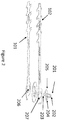
- the rotational motion of the electric motor is converted into translational reciprocating motion by means of an eccentric rotor, typically as shown in figures 2 and 3 .
- the eccentric rotor comprises a shaft 201 with an upper portion 202 and a lower portion 203 and two eccentric discs 204, 205.
- the upper portion of the shaft is directly connected to the output shaft of a gearbox, a clutch or directly to a motor, and the lower portion is mounted in a bearing to provide stability for the arrangement.
- the upper portion is wider than the lower, since it is subject to greater stresses.
- Each blade 101, 102 has an aperture 206, 207 which receives an eccentric disc. The rotation the shaft causes rotation of the eccentric discs, which causes reciprocating motion of the blade.
- Figure 3 is a side view of a section of the drive shaft 201 according to the prior art, showing the eccentric discs 204, 205, the wider upper portion 202 of the drive shaft and the narrower lower portion 203 of the drive shaft 201.
- Lubrication of this blade and rotor arrangement is essential for the working of the hedge cutter and for prolonging its useful life.
- the conventional disassembly of such a device for lubrication is difficult for the amateur gardener and inconvenient for the amateur and professional alike.
- the inclusion of lubrication channels in the drive shaft risks weakening the structure and compromising the integrity and working life of the device.
- the present invention discloses that correct positioning of lubrication holes can overcome this problem, whilst still enabling lubricating medium to be brought into contact with rotor and eccentric discs alike.
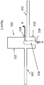
- FIG 4 is a cross-sectional view of a drive shaft with an eccentric disc arrangement according to an embodiment of the invention.
- This embodiment comprises a lubrication channel 401, drilled axially into drive shaft 201, with lubrication inlet 402 and a lubrication outlet 403 extending from the lubrication channel.
- lubrication channel 401 comprises main channel 404 and at least one side channel 405.
- the hedge cutter may be inverted and lubrication medium (e.g. oil or grease) supplied to inlet 402.
- lubrication medium e.g. oil or grease
- Figure 6 is a cross sectional view of another embodiment of the invention, with a second lubrication outlet 601. Having two lubrication outlets helps to ensure both eccentric discs are evenly lubricated.
- Figure 8 is a cross sectional view of the stresses induced by the rotation of the drive shaft, showing an axial view of one of the lubrication outlets 403.
- the outlet is located substantially at the terminating point 801 of lubrication channel 401.
- Regions of high stress 802 are located around lubrication outlet 403. The presence of high stresses can cause stress fractures and hence shorten the life of the product.
- the lubrication channel is longer than in the embodiment of Figure 8 .
- Figure 9 is a cross sectional view of this embodiment, in which the outlet is spaced from the terminating point of the main channel, for example by a dead-end section 901. This additional section moves the high stress region associated with the terminating point away from the outlet.
- the terminating point may be spaced from the outlet by about 1-10mm, although only 1-2mm spacing may be necessary in some cases to achieve the desired result.
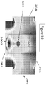
- Figure 10 is a cross sectional view showing the stress map of the embodiment of Figure 9 when in use. It can be seen that the high stress region 1001 is now away from the lubricating outlet 403. This reduces the possibility of stress fractures around the lubricating outlet.
- Figure 11 is a cross section of yet another embodiment of the invention.
- the termination of the lubricating channel comprises a dome shape 1101.
- This dome shape eliminates sharp corners around which stresses can occur, thus further reducing the possibility of the development of stress fractures at these points.
- the success of the combination of the widening of the lower drive shaft, the dead-end section of the lubricating channel and the rounding of the lubricating channel terminating point can be seen in the stress patterns in the resulting drive shaft when in action.
- Figure 12 is a cross sectional stress map for the embodiment of Figure 11 in use, showing the high stress regions 1201.
- Figure 13 is a plan view stress map for the embodiment of Figure 11 in use, showing high stress regions 1301. In both cases, the stress maps are the same as for eccentrics with no lubrication channels. Consequently, the addition of the lubrication channels and the outlets can be used to provide easy lubrication without compromising the structural integrity of the drive shaft.
Landscapes
- Engineering & Computer Science (AREA)
- General Engineering & Computer Science (AREA)
- Mechanical Engineering (AREA)
- Life Sciences & Earth Sciences (AREA)
- Biodiversity & Conservation Biology (AREA)
- Ecology (AREA)
- Forests & Forestry (AREA)
- Environmental Sciences (AREA)
- Harvester Elements (AREA)
- General Details Of Gearings (AREA)
Description
- The invention relates to lubrication for eccentric rotors, and in particular lubrication for eccentric rotors in cutting apparatus such as hedge cutters.
- Hedge cutters with elongate blades which reciprocate with respect to each other are well known, with either one blade being fixed and the other caused to reciprocate or both blades reciprocating in an equal and opposite manner. The blades are driven by a cam element driven by the output shaft of an electric motor or small engine.
- A typical example of such an arrangement is disclosed in
EP2666389 . An arrangement with two reciprocating blades is described with a mechanism for enacting reciprocation using a rotor, driven by a prime mover such as an electric or petrol motor, whose rotational motion is converted into reciprocating translational motion using two eccentric discs, which are received by an aperture or "eye" in each blade section. - The arrangement is very effective for enabling cutting using reciprocating blades. However, a problem with this arrangement is the requirement for lubrication of the eccentric discs and blades. Current hedge cutters require disassembly of the eccentric rotor and blade arrangement in order to provide the necessary lubrication. This is inconvenient for a professional user, whose time is important. The non-professional user may experience difficulties in the disassembly and reassembly and may as a result be deterred from implementing the necessary lubrication with a detrimental effect on the life of the product. Furthermore reference is made to the documents
US20050009659 A1 andEP1493317 A1 . - Accordingly, in a first aspect, the present invention provides an eccentric rotor for a cutting apparatus comprising a drive shaft and first and second eccentric discs mounted on the drive shaft and projecting radially therefrom, characterised in that a lubrication channel is provided within the drive shaft which extends from an inlet, preferably provided at or adjacent to one end of the drive shaft, to an outlet provided adjacent to at least one of the first and second eccentric discs.
- Preferably, the outlet is provided in the circumferential surface of the drive shaft.
- In preferred arrangements, the lubrication channel comprises a main channel and an outlet channel extending from the main channel to the outlet. The main channel may extend substantially coaxially with the axis of rotation of the drive shaft. The inlet is preferably centred on the end of the drive shaft and aligned with the axis of rotation of the drive shaft. The outlet channel may extend substantially radially from the main channel to the outlet.
- In preferred embodiments, the main channel will terminate at a terminating point. Preferably, the terminating point is substantially dome-shaped. The terminating point is preferably spaced axially from the outlet.
- Preferably, the first and second eccentric discs are mounted on the drive shaft intermediate the ends of the drive shaft, dividing the drive shaft into upper and lower portions. The inlet is preferably located in the lower portion and the outlet is located in the upper portion.
- A second outlet may be provided adjacent to at least one of the first and second eccentric discs. In this arrangement, the first outlet may be adjacent to one of the first and second eccentric discs and the second outlet may be adjacent to the other of the first and second eccentric discs. In the embodiment above in which the inlet is located in the lower portion of the drive shaft and the outlet is located in the upper portion, the second outlet is preferably located in the lower portion.
- The invention extends to a cutting apparatus comprising an eccentric rotor as described above. Preferably, the inlet is accessible when the apparatus is fully assembled.
- The invention also extends to a method for lubricating at least one of the eccentric discs of an eccentric rotor for a cutting apparatus comprising a drive shaft and first and second eccentric discs mounted on the drive shaft and projecting radially therefrom, characterised in that a lubricant is fed through a lubrication channel which is provided within the drive shaft and extends from an inlet, preferably provided at or adjacent to one end of the drive shaft, to an outlet provided adjacent to at least one of the first and second eccentric discs by additional means.
- In preferred embodiments, the additional means may be manual or automatic. Preferably the additional means comprises a detachable grease gun or a non detachable automatic grease applying apparatus. The non detachable automatic grease applying apparatus may be installed with a grease reservoir within the cutting apparatus.
- The above and other aspects of the present invention will be described, by way of example only, with reference to the following diagrams, in which:
-
Figure 1 is a perspective view of a hedge cutter with reciprocating blades; -
Figure 2 is an exploded view of the rotor and blade arrangement; -
Figure 3 is a side view of a drive shaft according to the prior art; -
Figure 4 is a cross-sectional view of a drive shaft with a lubricating channel according an embodiment of the invention; -
Figure 5 is a cross sectional view of the embodiment ofFigure 4 during lubrication; -
Figure 6 is a cross sectional view of a drive shaft with lubricating channel according to another embodiment of the invention; -
Figure 7 is a side view of a drive shaft in accordance with another embodiment of the invention; -
Figure 8 is a cross sectional stress map of the lubricating channel of the embodiment ofFigure 7 when in use; -
Figure 9 is a cross sectional view of a drive shaft of another embodiment of the invention; -
Figure 10 is a cross sectional stress map of the lubricating channel of the embodiment ofFigure 9 when in use; -
Figure 11 is a cross section of a drive shaft according to another embodiment of the invention; -
Figure 12 is a cross sectional stress map of the embodiment ofFigure 11 in use; and -
Figure 13 is a plan view stress map of the embodiment ofFigure 11 in use. -
Figure 1 shows a typical electric hedge cutter. The hedge cutter has abottom blade 101 and anupper blade 102 which are caused to reciprocate simultaneously in an equal and opposite manner with respect to thehousing 103 and to each other by means of an electric motor within the housing unit. The rotational motion of the electric motor is converted into translational reciprocating motion by means of an eccentric rotor, typically as shown infigures 2 and3 . The eccentric rotor comprises ashaft 201 with anupper portion 202 and alower portion 203 and twoeccentric discs blade aperture -
Figure 3 is a side view of a section of thedrive shaft 201 according to the prior art, showing theeccentric discs upper portion 202 of the drive shaft and the narrowerlower portion 203 of thedrive shaft 201. - Lubrication of this blade and rotor arrangement is essential for the working of the hedge cutter and for prolonging its useful life. The conventional disassembly of such a device for lubrication is difficult for the amateur gardener and inconvenient for the amateur and professional alike. However, it is generally considered in the art that the inclusion of lubrication channels in the drive shaft risks weakening the structure and compromising the integrity and working life of the device. The present invention discloses that correct positioning of lubrication holes can overcome this problem, whilst still enabling lubricating medium to be brought into contact with rotor and eccentric discs alike.
-
Figure 4 is a cross-sectional view of a drive shaft with an eccentric disc arrangement according to an embodiment of the invention. This embodiment comprises alubrication channel 401, drilled axially intodrive shaft 201, withlubrication inlet 402 and alubrication outlet 403 extending from the lubrication channel. In an embodiment,lubrication channel 401 comprisesmain channel 404 and at least oneside channel 405. When lubrication is required, the hedge cutter may be inverted and lubrication medium (e.g. oil or grease) supplied toinlet 402. This process is shown inFigure 5 , with lubrication medium being supplied to lubrication inlet 402 (arrow A), which is in fluid communication withoutlet 403, resulting in lubrication medium exiting from lubrication outlet 403 (arrow B) and hence covering theeccentric discs -
Figure 6 is a cross sectional view of another embodiment of the invention, with asecond lubrication outlet 601. Having two lubrication outlets helps to ensure both eccentric discs are evenly lubricated. - The provision of a lubricating channel however potentially creates problems in that the presence of the channels can weaken the structure of the drive shaft, causing excess stresses and ultimately reducing the life of the product. In another embodiment of the invention therefore the drive shaft is strengthened by having both upper and lower portions of the shaft substantially the same diameter. In prior art systems, such as that of
EP 2266389 , the majority of the stress of rotation is taken by the upper shaft. The strengthening of the lower shaft assists in overcoming structural weakness introduced by the lubrication channels.Figure 7 is a side view of this embodiment, showingupper portion 202 andlower portion 203 of substantially equal diameter. - In spite of the strengthening of the drive shaft by having equal upper and lower portions, problems may still arise from the presence of the lubricating channel, in the form of stresses in the regions around the channel and particularly at any corners of such a channel.
Figure 8 is a cross sectional view of the stresses induced by the rotation of the drive shaft, showing an axial view of one of thelubrication outlets 403. In this embodiment, the outlet is located substantially at the terminatingpoint 801 oflubrication channel 401. Regions ofhigh stress 802 are located aroundlubrication outlet 403. The presence of high stresses can cause stress fractures and hence shorten the life of the product. - In yet another embodiment of the invention, the lubrication channel is longer than in the embodiment of
Figure 8 .Figure 9 is a cross sectional view of this embodiment, in which the outlet is spaced from the terminating point of the main channel, for example by a dead-end section 901. This additional section moves the high stress region associated with the terminating point away from the outlet. Typically, the terminating point may be spaced from the outlet by about 1-10mm, although only 1-2mm spacing may be necessary in some cases to achieve the desired result. -
Figure 10 is a cross sectional view showing the stress map of the embodiment ofFigure 9 when in use. It can be seen that thehigh stress region 1001 is now away from thelubricating outlet 403. This reduces the possibility of stress fractures around the lubricating outlet. -
Figure 11 is a cross section of yet another embodiment of the invention. In this embodiment, the termination of the lubricating channel comprises adome shape 1101. This dome shape eliminates sharp corners around which stresses can occur, thus further reducing the possibility of the development of stress fractures at these points. The success of the combination of the widening of the lower drive shaft, the dead-end section of the lubricating channel and the rounding of the lubricating channel terminating point can be seen in the stress patterns in the resulting drive shaft when in action.Figure 12 is a cross sectional stress map for the embodiment ofFigure 11 in use, showing thehigh stress regions 1201.Figure 13 is a plan view stress map for the embodiment ofFigure 11 in use, showinghigh stress regions 1301. In both cases, the stress maps are the same as for eccentrics with no lubrication channels. Consequently, the addition of the lubrication channels and the outlets can be used to provide easy lubrication without compromising the structural integrity of the drive shaft. - The present invention is not limited to the details of the embodiments described above but is limited only by the appended claims. The person skilled in the art will appreciate that any combination of stress reducing adaptations may be used, for example a dome shaped terminating point may be used in combination with outlets substantially located at the end of the lubricating channel.
Claims (14)
- An eccentric rotor for a cutting apparatus such as hedge cutters comprising a drive shaft (201) and first and second eccentric discs (204,205) mounted on the drive shaft (201) and projecting radially therefrom, characterised in that a lubrication channel (401) is provided within the drive shaft (201) which extends from an inlet (402), preferably provided at or adjacent to one end of the drive shaft (201), to an outlet (403), whereby the outlet (403) is provided adjacent to at least one of the first and second eccentric discs (204,205).
- The eccentric rotor of claim 1, wherein the outlet (403) is provided in the circumferential surface of the drive shaft (201).
- The eccentric rotor of claim 1 or 2, wherein the lubrication channel (401) comprises a main channel (404) and an outlet channel (405) extending from the main channel to the outlet (403).
- The eccentric rotor of claim 3, wherein the main channel (404) extends substantially coaxially with the axis of rotation of the drive shaft (201).
- The eccentric rotor of claim 4, wherein the inlet (402) is centred on the end of the drive shaft (201) and aligned with the axis of rotation of the drive shaft.
- The eccentric rotor of claim 3, 4 or 5, wherein the outlet channel (405) extends substantially radially from the main channel (404) to the outlet (403).
- The eccentric rotor of any of claims 3 to 6, wherein the main channel (404) terminates at a terminating point (801) preferably being substantially dome-shaped and being spaced axially from the outlet (403).
- The eccentric rotor of any preceding claim, wherein the first and second eccentric discs (204,205) are mounted on the drive shaft (201) intermediate the ends of the drive shaft, dividing the drive shaft into upper and lower portions (202,203), and wherein the inlet (402) is located in the lower portion (203) and the outlet (403) is located in the upper portion (202).
- The eccentric rotor of any preceding claim, wherein at least a second outlet (601) is provided adjacent to at least one of the first and second eccentric discs (204,205).
- The eccentric rotor of claim 9, wherein the first outlet (403) is adjacent to one of the first and second eccentric discs (204,205) and the second outlet is adjacent to the other of the first and second eccentric discs (204,205).
- The eccentric rotor of claim 8 and claim 9 or 10, wherein the second outlet (601) is located in the lower portion (203).
- A cutting apparatus comprising an eccentric rotor as claimed in any preceding claim.
- A method for lubricating at least one of the eccentric discs (204,205) of an eccentric rotor for a cutting apparatus such as hedge cutters comprising a drive shaft (201) and first and second eccentric discs (204,205) mounted on the drive shaft (201) and projecting radially therefrom, characterised in that a lubricant is fed through a lubrication channel (401) which is provided within the drive shaft (201) and extends from an inlet (402), preferably provided at or adjacent to one end of the drive shaft (201), to an outlet (403), whereby the outlet (403) is provided adjacent to at least one of the first and second eccentric discs (204,205) by additional means.
- The method for lubricating according to claim 13, wherein the additional means are manual or automatic means, preferably a detachable grease gun or a non detachable automatic grease applying apparatus, preferably installed with a grease reservoir within the cutting apparatus.
Priority Applications (1)
| Application Number | Priority Date | Filing Date | Title |
|---|---|---|---|
| EP14181073.9A EP2984923B1 (en) | 2014-08-14 | 2014-08-14 | Eccentric rotor with lubrication for a cutting apparatus and a method for lubricating the same |
Applications Claiming Priority (1)
| Application Number | Priority Date | Filing Date | Title |
|---|---|---|---|
| EP14181073.9A EP2984923B1 (en) | 2014-08-14 | 2014-08-14 | Eccentric rotor with lubrication for a cutting apparatus and a method for lubricating the same |
Publications (2)
| Publication Number | Publication Date |
|---|---|
| EP2984923A1 EP2984923A1 (en) | 2016-02-17 |
| EP2984923B1 true EP2984923B1 (en) | 2020-11-04 |
Family
ID=51389900
Family Applications (1)
| Application Number | Title | Priority Date | Filing Date |
|---|---|---|---|
| EP14181073.9A Active EP2984923B1 (en) | 2014-08-14 | 2014-08-14 | Eccentric rotor with lubrication for a cutting apparatus and a method for lubricating the same |
Country Status (1)
| Country | Link |
|---|---|
| EP (1) | EP2984923B1 (en) |
Family Cites Families (5)
| Publication number | Priority date | Publication date | Assignee | Title |
|---|---|---|---|---|
| EP1493317B1 (en) * | 2003-07-02 | 2006-08-23 | HONDA MOTOR CO., Ltd. | Bush cutter |
| TWM249458U (en) * | 2003-07-08 | 2004-11-11 | Yu-Shiang Huang | Structure of gear box for gardening device |
| JP5205327B2 (en) * | 2009-03-31 | 2013-06-05 | 株式会社マキタ | Lubrication structure of work equipment |
| EP2266389B1 (en) | 2009-06-25 | 2017-06-21 | Robert Bosch Gmbh | Cutting tools |
| FR2990833B1 (en) | 2012-05-23 | 2017-01-06 | Tournadre Sa Standard Gum | SUSPENSION DEVICE FOR SOMMIER WITH ADJUSTABLE STIFFNESS |
-
2014
- 2014-08-14 EP EP14181073.9A patent/EP2984923B1/en active Active
Non-Patent Citations (1)
| Title |
|---|
| None * |
Also Published As
| Publication number | Publication date |
|---|---|
| EP2984923A1 (en) | 2016-02-17 |
Similar Documents
| Publication | Publication Date | Title |
|---|---|---|
| CN102480916B (en) | Cutting assembly for hand-held power tool | |
| US9470303B2 (en) | Self scavenging gear shield | |
| DE102005031197B4 (en) | Drive and fan | |
| EP2415343B1 (en) | Lubricating structure for working device | |
| US9780625B2 (en) | Cooling stator coils of an electric motor | |
| DE202017107511U1 (en) | Power tool and its transmission shaft assembly | |
| CN102480920A (en) | Motor-Driven Handheld Cutting Device, Method For Producing Same, And Double Blade Arrangement | |
| EP3051954B1 (en) | Dehiding tool | |
| EP4000368A1 (en) | Reciprocating cutting blade device and reaper | |
| US20020053140A1 (en) | Eccentric drive including an eccentric drive for a portable handheld work apparatus | |
| DE102004019009A1 (en) | Transmission for a gardening machine | |
| EP2984923A1 (en) | Excentric rotor with lubrication for a cutting apparatus and a method for lubricating the same | |
| DE102005016628A1 (en) | Hand-held brush cutter | |
| USH1428H (en) | Reciprocating cutter type trimmer | |
| DE102010040131A1 (en) | Oscillating insert tool and hole saw insert tool | |
| WO2003030296A3 (en) | Rotor for vane pump | |
| DE102004046160A1 (en) | Fuel pump | |
| EP0700632A1 (en) | A cutting section for a cutting machine such as a mower or hedge trimmer | |
| EP3509199B1 (en) | Main generator stator sleeve for integrated drive generator | |
| JP2016148371A (en) | Vehicular shaft | |
| US11349363B2 (en) | Lamination for main generator rotor in an integrated drive generator | |
| EP3514398B1 (en) | Fixed block shaft inner bearing race for integrated drive generator | |
| WO2021023603A1 (en) | Watertight and stiff motor suspension | |
| CN107532695B (en) | For with the bevel gear arrangements structure of the driven mower blade of mode of oscillation | |
| EP3467349B1 (en) | Accessory drive gear for integrated drive generator |
Legal Events
| Date | Code | Title | Description |
|---|---|---|---|
| PUAI | Public reference made under article 153(3) epc to a published international application that has entered the european phase |
Free format text: ORIGINAL CODE: 0009012 |
|
| AK | Designated contracting states |
Kind code of ref document: A1 Designated state(s): AL AT BE BG CH CY CZ DE DK EE ES FI FR GB GR HR HU IE IS IT LI LT LU LV MC MK MT NL NO PL PT RO RS SE SI SK SM TR |
|
| AX | Request for extension of the european patent |
Extension state: BA ME |
|
| 17P | Request for examination filed |
Effective date: 20160817 |
|
| RBV | Designated contracting states (corrected) |
Designated state(s): AL AT BE BG CH CY CZ DE DK EE ES FI FR GB GR HR HU IE IS IT LI LT LU LV MC MK MT NL NO PL PT RO RS SE SI SK SM TR |
|
| STAA | Information on the status of an ep patent application or granted ep patent |
Free format text: STATUS: EXAMINATION IS IN PROGRESS |
|
| 17Q | First examination report despatched |
Effective date: 20200206 |
|
| RAP1 | Party data changed (applicant data changed or rights of an application transferred) |
Owner name: ROBERT BOSCH GMBH |
|
| GRAP | Despatch of communication of intention to grant a patent |
Free format text: ORIGINAL CODE: EPIDOSNIGR1 |
|
| STAA | Information on the status of an ep patent application or granted ep patent |
Free format text: STATUS: GRANT OF PATENT IS INTENDED |
|
| INTG | Intention to grant announced |
Effective date: 20200715 |
|
| RIN1 | Information on inventor provided before grant (corrected) |
Inventor name: GILBERT, AUSTEN Inventor name: THORNTON, DARREN |
|
| GRAS | Grant fee paid |
Free format text: ORIGINAL CODE: EPIDOSNIGR3 |
|
| GRAA | (expected) grant |
Free format text: ORIGINAL CODE: 0009210 |
|
| STAA | Information on the status of an ep patent application or granted ep patent |
Free format text: STATUS: THE PATENT HAS BEEN GRANTED |
|
| AK | Designated contracting states |
Kind code of ref document: B1 Designated state(s): AL AT BE BG CH CY CZ DE DK EE ES FI FR GB GR HR HU IE IS IT LI LT LU LV MC MK MT NL NO PL PT RO RS SE SI SK SM TR |
|
| REG | Reference to a national code |
Ref country code: GB Ref legal event code: FG4D |
|
| REG | Reference to a national code |
Ref country code: CH Ref legal event code: EP |
|
| REG | Reference to a national code |
Ref country code: AT Ref legal event code: REF Ref document number: 1329611 Country of ref document: AT Kind code of ref document: T Effective date: 20201115 |
|
| REG | Reference to a national code |
Ref country code: IE Ref legal event code: FG4D |
|
| REG | Reference to a national code |
Ref country code: DE Ref legal event code: R096 Ref document number: 602014071910 Country of ref document: DE |
|
| REG | Reference to a national code |
Ref country code: NL Ref legal event code: MP Effective date: 20201104 |
|
| REG | Reference to a national code |
Ref country code: AT Ref legal event code: MK05 Ref document number: 1329611 Country of ref document: AT Kind code of ref document: T Effective date: 20201104 |
|
| PG25 | Lapsed in a contracting state [announced via postgrant information from national office to epo] |
Ref country code: RS Free format text: LAPSE BECAUSE OF FAILURE TO SUBMIT A TRANSLATION OF THE DESCRIPTION OR TO PAY THE FEE WITHIN THE PRESCRIBED TIME-LIMIT Effective date: 20201104 Ref country code: FI Free format text: LAPSE BECAUSE OF FAILURE TO SUBMIT A TRANSLATION OF THE DESCRIPTION OR TO PAY THE FEE WITHIN THE PRESCRIBED TIME-LIMIT Effective date: 20201104 Ref country code: PT Free format text: LAPSE BECAUSE OF FAILURE TO SUBMIT A TRANSLATION OF THE DESCRIPTION OR TO PAY THE FEE WITHIN THE PRESCRIBED TIME-LIMIT Effective date: 20210304 Ref country code: NO Free format text: LAPSE BECAUSE OF FAILURE TO SUBMIT A TRANSLATION OF THE DESCRIPTION OR TO PAY THE FEE WITHIN THE PRESCRIBED TIME-LIMIT Effective date: 20210204 Ref country code: GR Free format text: LAPSE BECAUSE OF FAILURE TO SUBMIT A TRANSLATION OF THE DESCRIPTION OR TO PAY THE FEE WITHIN THE PRESCRIBED TIME-LIMIT Effective date: 20210205 |
|
| PG25 | Lapsed in a contracting state [announced via postgrant information from national office to epo] |
Ref country code: LV Free format text: LAPSE BECAUSE OF FAILURE TO SUBMIT A TRANSLATION OF THE DESCRIPTION OR TO PAY THE FEE WITHIN THE PRESCRIBED TIME-LIMIT Effective date: 20201104 Ref country code: SE Free format text: LAPSE BECAUSE OF FAILURE TO SUBMIT A TRANSLATION OF THE DESCRIPTION OR TO PAY THE FEE WITHIN THE PRESCRIBED TIME-LIMIT Effective date: 20201104 Ref country code: IS Free format text: LAPSE BECAUSE OF FAILURE TO SUBMIT A TRANSLATION OF THE DESCRIPTION OR TO PAY THE FEE WITHIN THE PRESCRIBED TIME-LIMIT Effective date: 20210304 Ref country code: PL Free format text: LAPSE BECAUSE OF FAILURE TO SUBMIT A TRANSLATION OF THE DESCRIPTION OR TO PAY THE FEE WITHIN THE PRESCRIBED TIME-LIMIT Effective date: 20201104 Ref country code: AT Free format text: LAPSE BECAUSE OF FAILURE TO SUBMIT A TRANSLATION OF THE DESCRIPTION OR TO PAY THE FEE WITHIN THE PRESCRIBED TIME-LIMIT Effective date: 20201104 Ref country code: ES Free format text: LAPSE BECAUSE OF FAILURE TO SUBMIT A TRANSLATION OF THE DESCRIPTION OR TO PAY THE FEE WITHIN THE PRESCRIBED TIME-LIMIT Effective date: 20201104 Ref country code: BG Free format text: LAPSE BECAUSE OF FAILURE TO SUBMIT A TRANSLATION OF THE DESCRIPTION OR TO PAY THE FEE WITHIN THE PRESCRIBED TIME-LIMIT Effective date: 20210204 |
|
| REG | Reference to a national code |
Ref country code: LT Ref legal event code: MG9D |
|
| PG25 | Lapsed in a contracting state [announced via postgrant information from national office to epo] |
Ref country code: HR Free format text: LAPSE BECAUSE OF FAILURE TO SUBMIT A TRANSLATION OF THE DESCRIPTION OR TO PAY THE FEE WITHIN THE PRESCRIBED TIME-LIMIT Effective date: 20201104 |
|
| PG25 | Lapsed in a contracting state [announced via postgrant information from national office to epo] |
Ref country code: SK Free format text: LAPSE BECAUSE OF FAILURE TO SUBMIT A TRANSLATION OF THE DESCRIPTION OR TO PAY THE FEE WITHIN THE PRESCRIBED TIME-LIMIT Effective date: 20201104 Ref country code: RO Free format text: LAPSE BECAUSE OF FAILURE TO SUBMIT A TRANSLATION OF THE DESCRIPTION OR TO PAY THE FEE WITHIN THE PRESCRIBED TIME-LIMIT Effective date: 20201104 Ref country code: LT Free format text: LAPSE BECAUSE OF FAILURE TO SUBMIT A TRANSLATION OF THE DESCRIPTION OR TO PAY THE FEE WITHIN THE PRESCRIBED TIME-LIMIT Effective date: 20201104 Ref country code: EE Free format text: LAPSE BECAUSE OF FAILURE TO SUBMIT A TRANSLATION OF THE DESCRIPTION OR TO PAY THE FEE WITHIN THE PRESCRIBED TIME-LIMIT Effective date: 20201104 Ref country code: CZ Free format text: LAPSE BECAUSE OF FAILURE TO SUBMIT A TRANSLATION OF THE DESCRIPTION OR TO PAY THE FEE WITHIN THE PRESCRIBED TIME-LIMIT Effective date: 20201104 Ref country code: SM Free format text: LAPSE BECAUSE OF FAILURE TO SUBMIT A TRANSLATION OF THE DESCRIPTION OR TO PAY THE FEE WITHIN THE PRESCRIBED TIME-LIMIT Effective date: 20201104 |
|
| REG | Reference to a national code |
Ref country code: DE Ref legal event code: R097 Ref document number: 602014071910 Country of ref document: DE |
|
| PG25 | Lapsed in a contracting state [announced via postgrant information from national office to epo] |
Ref country code: DK Free format text: LAPSE BECAUSE OF FAILURE TO SUBMIT A TRANSLATION OF THE DESCRIPTION OR TO PAY THE FEE WITHIN THE PRESCRIBED TIME-LIMIT Effective date: 20201104 |
|
| PLBE | No opposition filed within time limit |
Free format text: ORIGINAL CODE: 0009261 |
|
| STAA | Information on the status of an ep patent application or granted ep patent |
Free format text: STATUS: NO OPPOSITION FILED WITHIN TIME LIMIT |
|
| 26N | No opposition filed |
Effective date: 20210805 |
|
| PG25 | Lapsed in a contracting state [announced via postgrant information from national office to epo] |
Ref country code: IT Free format text: LAPSE BECAUSE OF FAILURE TO SUBMIT A TRANSLATION OF THE DESCRIPTION OR TO PAY THE FEE WITHIN THE PRESCRIBED TIME-LIMIT Effective date: 20201104 Ref country code: NL Free format text: LAPSE BECAUSE OF FAILURE TO SUBMIT A TRANSLATION OF THE DESCRIPTION OR TO PAY THE FEE WITHIN THE PRESCRIBED TIME-LIMIT Effective date: 20201104 Ref country code: AL Free format text: LAPSE BECAUSE OF FAILURE TO SUBMIT A TRANSLATION OF THE DESCRIPTION OR TO PAY THE FEE WITHIN THE PRESCRIBED TIME-LIMIT Effective date: 20201104 |
|
| PG25 | Lapsed in a contracting state [announced via postgrant information from national office to epo] |
Ref country code: SI Free format text: LAPSE BECAUSE OF FAILURE TO SUBMIT A TRANSLATION OF THE DESCRIPTION OR TO PAY THE FEE WITHIN THE PRESCRIBED TIME-LIMIT Effective date: 20201104 |
|
| REG | Reference to a national code |
Ref country code: CH Ref legal event code: PL |
|
| PG25 | Lapsed in a contracting state [announced via postgrant information from national office to epo] |
Ref country code: MC Free format text: LAPSE BECAUSE OF FAILURE TO SUBMIT A TRANSLATION OF THE DESCRIPTION OR TO PAY THE FEE WITHIN THE PRESCRIBED TIME-LIMIT Effective date: 20201104 |
|
| REG | Reference to a national code |
Ref country code: BE Ref legal event code: MM Effective date: 20210831 |
|
| PG25 | Lapsed in a contracting state [announced via postgrant information from national office to epo] |
Ref country code: LI Free format text: LAPSE BECAUSE OF NON-PAYMENT OF DUE FEES Effective date: 20210831 Ref country code: CH Free format text: LAPSE BECAUSE OF NON-PAYMENT OF DUE FEES Effective date: 20210831 |
|
| PG25 | Lapsed in a contracting state [announced via postgrant information from national office to epo] |
Ref country code: IS Free format text: LAPSE BECAUSE OF FAILURE TO SUBMIT A TRANSLATION OF THE DESCRIPTION OR TO PAY THE FEE WITHIN THE PRESCRIBED TIME-LIMIT Effective date: 20210304 Ref country code: LU Free format text: LAPSE BECAUSE OF NON-PAYMENT OF DUE FEES Effective date: 20210814 |
|
| PG25 | Lapsed in a contracting state [announced via postgrant information from national office to epo] |
Ref country code: IE Free format text: LAPSE BECAUSE OF NON-PAYMENT OF DUE FEES Effective date: 20210814 Ref country code: BE Free format text: LAPSE BECAUSE OF NON-PAYMENT OF DUE FEES Effective date: 20210831 |
|
| PG25 | Lapsed in a contracting state [announced via postgrant information from national office to epo] |
Ref country code: HU Free format text: LAPSE BECAUSE OF FAILURE TO SUBMIT A TRANSLATION OF THE DESCRIPTION OR TO PAY THE FEE WITHIN THE PRESCRIBED TIME-LIMIT; INVALID AB INITIO Effective date: 20140814 |
|
| PG25 | Lapsed in a contracting state [announced via postgrant information from national office to epo] |
Ref country code: CY Free format text: LAPSE BECAUSE OF FAILURE TO SUBMIT A TRANSLATION OF THE DESCRIPTION OR TO PAY THE FEE WITHIN THE PRESCRIBED TIME-LIMIT Effective date: 20201104 |
|
| PG25 | Lapsed in a contracting state [announced via postgrant information from national office to epo] |
Ref country code: MK Free format text: LAPSE BECAUSE OF FAILURE TO SUBMIT A TRANSLATION OF THE DESCRIPTION OR TO PAY THE FEE WITHIN THE PRESCRIBED TIME-LIMIT Effective date: 20201104 |
|
| PG25 | Lapsed in a contracting state [announced via postgrant information from national office to epo] |
Ref country code: MT Free format text: LAPSE BECAUSE OF FAILURE TO SUBMIT A TRANSLATION OF THE DESCRIPTION OR TO PAY THE FEE WITHIN THE PRESCRIBED TIME-LIMIT Effective date: 20201104 |
|
| PGFP | Annual fee paid to national office [announced via postgrant information from national office to epo] |
Ref country code: GB Payment date: 20250822 Year of fee payment: 12 |
|
| PGFP | Annual fee paid to national office [announced via postgrant information from national office to epo] |
Ref country code: FR Payment date: 20250821 Year of fee payment: 12 |
|
| PG25 | Lapsed in a contracting state [announced via postgrant information from national office to epo] |
Ref country code: TR Free format text: LAPSE BECAUSE OF FAILURE TO SUBMIT A TRANSLATION OF THE DESCRIPTION OR TO PAY THE FEE WITHIN THE PRESCRIBED TIME-LIMIT Effective date: 20201104 |
|
| PGFP | Annual fee paid to national office [announced via postgrant information from national office to epo] |
Ref country code: DE Payment date: 20251021 Year of fee payment: 12 |