EP2984854B1 - Audio recording and playback apparatus - Google Patents
Audio recording and playback apparatus Download PDFInfo
- Publication number
- EP2984854B1 EP2984854B1 EP13881823.2A EP13881823A EP2984854B1 EP 2984854 B1 EP2984854 B1 EP 2984854B1 EP 13881823 A EP13881823 A EP 13881823A EP 2984854 B1 EP2984854 B1 EP 2984854B1
- Authority
- EP
- European Patent Office
- Prior art keywords
- audio
- microphone
- orientation
- microphones
- speaker
- Prior art date
- Legal status (The legal status is an assumption and is not a legal conclusion. Google has not performed a legal analysis and makes no representation as to the accuracy of the status listed.)
- Active
Links
- 230000005236 sound signal Effects 0.000 claims description 260
- 238000000926 separation method Methods 0.000 claims description 44
- 238000000034 method Methods 0.000 claims description 15
- 238000006073 displacement reaction Methods 0.000 claims description 11
- 238000009877 rendering Methods 0.000 description 34
- 230000005484 gravity Effects 0.000 description 15
- 230000011664 signaling Effects 0.000 description 12
- 238000013461 design Methods 0.000 description 9
- 238000010586 diagram Methods 0.000 description 9
- 238000004891 communication Methods 0.000 description 7
- 238000012545 processing Methods 0.000 description 7
- 239000004065 semiconductor Substances 0.000 description 6
- 230000008859 change Effects 0.000 description 5
- 230000000694 effects Effects 0.000 description 4
- 238000005516 engineering process Methods 0.000 description 4
- 230000007274 generation of a signal involved in cell-cell signaling Effects 0.000 description 4
- 238000004519 manufacturing process Methods 0.000 description 4
- 230000005540 biological transmission Effects 0.000 description 3
- 230000007246 mechanism Effects 0.000 description 3
- 238000006243 chemical reaction Methods 0.000 description 2
- 238000012937 correction Methods 0.000 description 2
- 230000008878 coupling Effects 0.000 description 2
- 238000010168 coupling process Methods 0.000 description 2
- 238000005859 coupling reaction Methods 0.000 description 2
- 230000001419 dependent effect Effects 0.000 description 2
- 230000006870 function Effects 0.000 description 2
- 238000012986 modification Methods 0.000 description 2
- 230000004048 modification Effects 0.000 description 2
- 230000003287 optical effect Effects 0.000 description 2
- OKTJSMMVPCPJKN-UHFFFAOYSA-N Carbon Chemical compound [C] OKTJSMMVPCPJKN-UHFFFAOYSA-N 0.000 description 1
- 230000006978 adaptation Effects 0.000 description 1
- 238000003491 array Methods 0.000 description 1
- 239000003990 capacitor Substances 0.000 description 1
- 229910052799 carbon Inorganic materials 0.000 description 1
- 230000001413 cellular effect Effects 0.000 description 1
- 230000008867 communication pathway Effects 0.000 description 1
- 238000004590 computer program Methods 0.000 description 1
- 239000004020 conductor Substances 0.000 description 1
- 238000013500 data storage Methods 0.000 description 1
- 238000003384 imaging method Methods 0.000 description 1
- 230000002452 interceptive effect Effects 0.000 description 1
- 238000004321 preservation Methods 0.000 description 1
- 230000008569 process Effects 0.000 description 1
- 238000013139 quantization Methods 0.000 description 1
- 230000009467 reduction Effects 0.000 description 1
- 239000007787 solid Substances 0.000 description 1
- 239000000758 substrate Substances 0.000 description 1
- 230000001360 synchronised effect Effects 0.000 description 1
- 230000000007 visual effect Effects 0.000 description 1
Images


Classifications
-
- H—ELECTRICITY
- H04—ELECTRIC COMMUNICATION TECHNIQUE
- H04S—STEREOPHONIC SYSTEMS
- H04S7/00—Indicating arrangements; Control arrangements, e.g. balance control
- H04S7/30—Control circuits for electronic adaptation of the sound field
- H04S7/301—Automatic calibration of stereophonic sound system, e.g. with test microphone
-
- H—ELECTRICITY
- H04—ELECTRIC COMMUNICATION TECHNIQUE
- H04R—LOUDSPEAKERS, MICROPHONES, GRAMOPHONE PICK-UPS OR LIKE ACOUSTIC ELECTROMECHANICAL TRANSDUCERS; DEAF-AID SETS; PUBLIC ADDRESS SYSTEMS
- H04R5/00—Stereophonic arrangements
- H04R5/02—Spatial or constructional arrangements of loudspeakers
-
- G—PHYSICS
- G06—COMPUTING; CALCULATING OR COUNTING
- G06F—ELECTRIC DIGITAL DATA PROCESSING
- G06F3/00—Input arrangements for transferring data to be processed into a form capable of being handled by the computer; Output arrangements for transferring data from processing unit to output unit, e.g. interface arrangements
- G06F3/16—Sound input; Sound output
- G06F3/165—Management of the audio stream, e.g. setting of volume, audio stream path
-
- H—ELECTRICITY
- H04—ELECTRIC COMMUNICATION TECHNIQUE
- H04R—LOUDSPEAKERS, MICROPHONES, GRAMOPHONE PICK-UPS OR LIKE ACOUSTIC ELECTROMECHANICAL TRANSDUCERS; DEAF-AID SETS; PUBLIC ADDRESS SYSTEMS
- H04R29/00—Monitoring arrangements; Testing arrangements
- H04R29/004—Monitoring arrangements; Testing arrangements for microphones
-
- H—ELECTRICITY
- H04—ELECTRIC COMMUNICATION TECHNIQUE
- H04R—LOUDSPEAKERS, MICROPHONES, GRAMOPHONE PICK-UPS OR LIKE ACOUSTIC ELECTROMECHANICAL TRANSDUCERS; DEAF-AID SETS; PUBLIC ADDRESS SYSTEMS
- H04R5/00—Stereophonic arrangements
- H04R5/04—Circuit arrangements, e.g. for selective connection of amplifier inputs/outputs to loudspeakers, for loudspeaker detection, or for adaptation of settings to personal preferences or hearing impairments
-
- H—ELECTRICITY
- H04—ELECTRIC COMMUNICATION TECHNIQUE
- H04S—STEREOPHONIC SYSTEMS
- H04S7/00—Indicating arrangements; Control arrangements, e.g. balance control
- H04S7/30—Control circuits for electronic adaptation of the sound field
-
- H—ELECTRICITY
- H04—ELECTRIC COMMUNICATION TECHNIQUE
- H04R—LOUDSPEAKERS, MICROPHONES, GRAMOPHONE PICK-UPS OR LIKE ACOUSTIC ELECTROMECHANICAL TRANSDUCERS; DEAF-AID SETS; PUBLIC ADDRESS SYSTEMS
- H04R2420/00—Details of connection covered by H04R, not provided for in its groups
- H04R2420/01—Input selection or mixing for amplifiers or loudspeakers
-
- H—ELECTRICITY
- H04—ELECTRIC COMMUNICATION TECHNIQUE
- H04R—LOUDSPEAKERS, MICROPHONES, GRAMOPHONE PICK-UPS OR LIKE ACOUSTIC ELECTROMECHANICAL TRANSDUCERS; DEAF-AID SETS; PUBLIC ADDRESS SYSTEMS
- H04R2420/00—Details of connection covered by H04R, not provided for in its groups
- H04R2420/03—Connection circuits to selectively connect loudspeakers or headphones to amplifiers
-
- H—ELECTRICITY
- H04—ELECTRIC COMMUNICATION TECHNIQUE
- H04R—LOUDSPEAKERS, MICROPHONES, GRAMOPHONE PICK-UPS OR LIKE ACOUSTIC ELECTROMECHANICAL TRANSDUCERS; DEAF-AID SETS; PUBLIC ADDRESS SYSTEMS
- H04R2499/00—Aspects covered by H04R or H04S not otherwise provided for in their subgroups
- H04R2499/10—General applications
- H04R2499/11—Transducers incorporated or for use in hand-held devices, e.g. mobile phones, PDA's, camera's
Definitions
- the present application relates to apparatus for audio recording and playback.
- the invention further relates to, but is not limited to, apparatus for audio recording and playback within mobile devices.
- a stereo or multi-channel recording can be passed from the recording or capture apparatus to a listening apparatus and replayed using a suitable multi-channel output such as a multi-channel loudspeaker arrangement and with virtual surround processing a pair of stereo headphones or headset.
- mobile devices will have the capacity to record (or capture) and play back stereophonic and surround sound audio.
- mobile devices will also be capable of passing these audio signals from device to device and as such can employ stereophonic and surround sound audio in telecommunication applications and also for other services such as streaming, broadcasting and multicasting when the audio recording or capture has been performed by a suitable or capable mobile device.
- EP2760223A1 describes a method for encoding a sound field.
- WO2012/061151A1 describes for orientation-sensitive selection and/or preservation of a recording direction using a multi-microphone
- EP1124175A2 describes an apparatus comprising an orientation sensitive user interface mechanism.
- WO2012/061149A1 describes a method for three-dimensional sound recording and reproduction using a multi-microphone setup
- an apparatus According to a first aspect, there is provided an apparatus according to claim 1.
- a computer program product stored on a medium may cause an apparatus to perform the method as described herein.
- An electronic device may comprise apparatus as described herein.
- a chipset may comprise apparatus as described herein.
- Embodiments of the present application aim to address problems associated with the state of the art.
- mobile devices or apparatus are more commonly being equipped with multiple microphone configurations or microphone arrays suitable for recording or capturing the audio environment or audio scene surrounding the mobile device or apparatus.
- a multiple microphone configuration enables the recording of stereo or surround sound signals.
- microphone locations at the 'bottom' and 'top' ends can be employed to pick up speech and reference noise in the hand-portable telephone application of the phone and these microphones reused in video/audio recording applications.
- mobile devices or apparatus are more commonly being equipped with multiple speaker configurations suitable for generating a suitable audio environment or audio scene in stereo or multichannel audio formats.
- mobile devices or apparatus such as smart phones
- microphones are also limited in both the number of microphones and their location. There are similar constraints to those for microphones as additional speakers increase size and manufacturing cost.
- the orientation of the device has a significant impact on the quality of the captured audio.
- a stereophonic capable device only able to capture stereophonic audio in one orientation relative to the phone (such as horizontal or vertical orientation due to the location of the microphones) will mean that changing the orientation of the device will also change the 'orientation' of the captured stereophonic audio signal.
- the user may sometimes prefer capturing video in portrait orientation and sometimes in landscape orientation, and change between these even during the same call. This can cause issues when the playback or rendering device is unaware of the orientation of the audio capture device and may prevent the correct playback of the stereophonic audio signal. This can therefore reduce the audio quality at the receiving end.
- the correction of video orientation in future devices using the GSMA Rich Communications Suite (RCS) 5.1 does not properly correct the audio orientation (i.e. the orientation of the captured audio signal) and can make the situation worse since the correction methods proposed may result into the audio and video orientations being out of synchronization (for example a sound source shown at the top of the screen being played out from a speaker located at the right or left hand side of the screen, or the sound source at the left hand side of the screen being played out from the right hand side of the screen).
- the audio recording system provides optimal pick up and stereo imaging for the desired recording distance whilst minimizing the number of microphones and taking into account limitations in microphone positioning.
- the concept as described in further detail herein is to provide a solution to align the use of speakers of the playback or rendering (receiving) device (or headphones or external loudspeakers) to the use of microphones in the recording or capturing (sending) device.
- the signaling in some embodiments can be performed as part of the audio data and sent throughout the transmission or as additional information sent only when the orientation of audio capture changes or when audio capture is performed at non-default orientation (such as vertical capture for stereophonic audio).
- the concept extends to apparatus and methods for providing the best possible audio quality at the rendering device when misalignment of audio orientation occurs between the capturing and rendering devices.
- the orientation of the audio capture device is detected by using a gravity sensor and by having knowledge of the audio capture properties of the device (in other words the number of the microphones and their positions together with knowledge about which microphones are used for which device orientation).
- the inclusion of signaling audio orientation can be performed by using Real Time Protocol (RTP) header extension.
- RTP Real Time Protocol
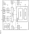
- Figure 1 shows a schematic block diagram of an exemplary apparatus or electronic device 10, which may be used to record (or operate as a capture apparatus) or playback (or operate as a rendering apparatus) audio signals.
- the electronic device 10 may for example be a mobile terminal or user equipment of a wireless communication system when functioning as the recording apparatus or listening apparatus.
- the apparatus can be an audio player or audio recorder, such as an MP3 player, a media recorder/player (also known as an MP4 player), or any suitable portable apparatus suitable for recording audio or audio/video camcorder/memory audio or video recorder.
- the apparatus 10 can in some embodiments comprise an audio-video subsystem.
- the audio-video subsystem for example can comprise in some embodiments a microphone or array of microphones 11 for audio signal capture.
- the microphone or array of microphones can be a solid state microphone, in other words capable of capturing audio signals and outputting a suitable digital format signal in other words not requiring an analogue-to-digital converter.
- the microphone or array of microphones 11 can comprise any suitable microphone or audio capture means, for example a condenser microphone, capacitor microphone, electrostatic microphone, electret condenser microphone, dynamic microphone, ribbon microphone, carbon microphone, piezoelectric microphone, or micro electrical-mechanical system (MEMS) microphone.
- the microphone 11 or array of microphones can in some embodiments output the audio captured signal to an analogue-to-digital converter (ADC) 14.
- ADC analogue-to-digital converter
- the apparatus can further comprise an analogue-to-digital converter (ADC) 14 configured to receive the analogue captured audio signal from the microphones and outputting the audio captured signal in a suitable digital form.
- ADC analogue-to-digital converter
- the analogue-to-digital converter 14 can be any suitable analogue-to-digital conversion or processing means, In some embodiments where the microphones are 'integrated' microphones the microphones contain both audio signal generating and analogue-to-digital conversion capability.
- the apparatus 10 audio-video subsystem further comprises a digital-to-analogue converter 32 for converting digital audio signals from a processor 21 to a suitable analogue format.
- the digital-to-analogue converter (DAC) or signal processing means 32 can in some embodiments be any suitable DAC technology.
- the audio-video subsystem can comprise in some embodiments a speaker 33.
- the speaker 33 can in some embodiments receive the output from the digital-to-analogue converter 32 and present the analogue audio signal to the user.
- the speaker 33 can be representative of multi-speaker arrangement, a headset, for example a set of headphones, or cordless headphones.
- the apparatus audio-video subsystem comprises a camera 51 or image capturing means configured to supply to the processor 21 image data.
- the camera can be configured to supply multiple images over time to provide a video stream.
- the apparatus audio-video subsystem comprises a display 52.
- the display or image display means can be configured to output visual images which can be viewed by the user of the apparatus.
- the display can be a touch screen display suitable for supplying input data to the apparatus.
- the display can be any suitable display technology, for example the display can be implemented by a flat panel comprising cells of LCD, LED, OLED, or 'plasma' display implementations.
- the apparatus 10 is shown having both audio/video capture and audio/video presentation components, it would be understood that in some embodiments the apparatus 10 can comprise only the audio capture or audio presentation parts of the audio subsystem such that in some embodiments of the apparatus the microphone (for audio capture) or the speaker (for audio playback or presentation) are present.
- the apparatus 10 comprises a processor 21.
- the processor 21 is coupled to the audio-video subsystem and specifically in some examples the analogue-to-digital converter 14 for receiving digital signals representing audio signals from the microphone 11, the digital-to-analogue converter (DAC) 12 configured to output processed digital audio signals, the camera 51 for receiving digital signals representing video signals, and the display 52 configured to output processed digital video signals from the processor 21.
- the analogue-to-digital converter 14 for receiving digital signals representing audio signals from the microphone 11
- the digital-to-analogue converter (DAC) 12 configured to output processed digital audio signals
- the camera 51 for receiving digital signals representing video signals
- the display 52 configured to output processed digital video signals from the processor 21.
- the processor 21 can be configured to execute various program codes.
- the implemented program codes can comprise for example audio recording and audio presentation routines according to some embodiments as described herein.
- the program codes can be configured to perform audio signal processing.
- the apparatus further comprises a memory 22.
- the processor is coupled to memory 22.
- the memory can be any suitable storage means.
- the memory 22 comprises a program code section 23 for storing program codes implementable upon the processor 21.
- the memory 22 can further comprise a stored data section 24 for storing data, for example data that has been encoded in accordance with the application or data to be encoded via the application embodiments as described later.
- the implemented program code stored within the program code section 23, and the data stored within the stored data section 24 can be retrieved by the processor 21 whenever needed via the memory-processor coupling.
- the apparatus 10 can comprise a user interface 15.
- the user interface 15 can be coupled in some embodiments to the processor 21.
- the processor can control the operation of the user interface and receive inputs from the user interface 15.
- the user interface 15 can enable a user to input commands to the electronic device or apparatus 10, for example via a keypad, and/or to obtain information from the apparatus 10, for example via a display which is part of the user interface 15.
- the user interface 15 can in some embodiments as described herein comprise a touch screen or touch interface capable of both enabling information to be entered to the apparatus 10 and further displaying information to the user of the apparatus 10.
- the apparatus further comprises a transceiver 13, the transceiver in such embodiments can be coupled to the processor and configured to enable a communication with other apparatus or electronic devices, for example via a wireless communications network.
- the transceiver 13 or any suitable transceiver or transmitter and/or receiver means can in some embodiments be configured to communicate with other electronic devices or apparatus via a wire or wired coupling.
- the transceiver 13 can communicate with further apparatus by any suitable known communications protocol, for example in some embodiments the transceiver 13 or transceiver means can use a suitable universal mobile telecommunications system (UMTS) protocol, a wireless local area network (WLAN) protocol such as for example IEEE 802.X, a suitable short-range radio frequency communication protocol such as Bluetooth, or infrared data communication pathway (IRDA).
- UMTS universal mobile telecommunications system
- WLAN wireless local area network
- IRDA infrared data communication pathway
- the apparatus comprises a position sensor 16 configured to estimate the position of the apparatus 10.
- the position sensor 16 can in some embodiments be a satellite positioning sensor such as a GPS (Global Positioning System), GLONASS or Galileo receiver.
- GPS Global Positioning System
- GLONASS Galileo receiver
- the positioning sensor can be a cellular ID system or an assisted GPS system.
- the apparatus 10 further comprises a direction or orientation sensor.
- the orientation/direction sensor can in some embodiments be an electronic compass, accelerometer, gyroscope or gravity sensor or be determined by the motion of the apparatus using the positioning estimate.
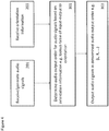
- FIG. 2 an example audio capture or recording apparatus configuration is shown according to some embodiments. Furthermore with respect to Figures 3 and 4 the operation of some embodiments of the audio capture or recording apparatus shown in Figure 2 is shown in further detail.
- the apparatus comprises the array of microphones 11 configured to record or capture the acoustic waves and generate an audio signal for each microphone which can be passed or input to the audio capture apparatus.
- the microphones 1 1 are configured to output an analogue signal which is converted into digital format by the analogue to digital converter (ADC) 14.
- ADC analogue to digital converter
- the microphones shown in the example herein are integrated microphones configured to output a digital format directly to a microphone order generator 103.
- the apparatus comprises three microphones.
- the first microphone (right microphone) 11 1 , and a second microphone (left microphone) 11 2 are located on the same 'vertical' plane on the same side of the apparatus as the camera hereby referred to as the front of the device.
- the apparatus comprises a third microphone (left rear microphone) 11 3 which is located on the same or similar horizontal plane on the opposite side to the front side containing the camera.
- the left rear microphone 11 3 is the conventional voice call microphone, and the first and second microphones the noise reducing microphones configured to capture the 'noise' to apply noise reduction or cancellation to the voice call audio signals.
- FIG. 25 shows an eight microphone configuration wherein eight microphones are located on a surface of the apparatus at 45° angles around a defined circle.
- a first microphone is located at 0°
- a second microphone at 45°
- a third microphone at 90°
- a fourth microphone at 135°
- a fifth microphone at 180°
- a sixth microphone at 225°
- a seventh microphone phone at 270°
- an eighth microphone at 315°.
- the multi-microphone configuration may be located on non-flat surface on the apparatus or be spread into more than one surface/side of the apparatus.
- the microphones are part of the apparatus it would be understood that in some embodiments the microphones or microphone array is physically separate from the apparatus, for example the microphone array can be located on a headset (where optionally the headset can have an associated video camera) which wirelessly or otherwise passes the audio signals to the apparatus for processing.
- the audio signals are generated in real-time by the microphones, in other words that there is generated at least two audio signals, the at least two audio signals having a relative displacement between them, that in some embodiments these audio signals can be understood to be received from a storage device or memory.
- the 'generating' the audio signals can be from recorded and stored audio signals (for example in an offline signal processing application).
- step 201 The operation of receiving or generating the audio signals is shown in Figures 3 and 4 by step 201.
- the apparatus comprises a gravity/orientation sensor 16.
- the gravity/orientation sensor 16 can be any suitable device or means for generating a signal and value which represents the apparatus orientation relative to a defined level.
- the gravity/orientation sensor 16 defines a value or generates a value of the apparatus with respect to the vertical plane and the level.
- the gravity/orientation sensor 16 is configured to determine the orientation in more than one plane, in other words to determine a roll, pitch and yaw rotation value.
- the embodiments as described herein describe the use or implementation of a roll orientation about the horizontal plane similar methods could be applied to pitch and yaw rotations or a combination of at least two of these.
- the gravity/orientation sensor 16 can in some embodiments output the orientation information to the audio orientation signal generator 101 and microphone order generator 103.
- the apparatus comprises an audio orientation signal generator 101.
- the audio orientation signal generator 101 is configured to receive the gravity/orientation sensor 16 output and determine firstly whether an audio orientation signal is to be generated and secondly the audio orientation signal to be output.
- the audio orientation signal generator 101 is configured to receive the orientation information.
- the audio orientation signal generator is configured to determine an audio orientation signal. In some embodiments this is generated whatever the orientation value is. However in some embodiments the determination of audio orientation signal (in other words whether an orientation signal is to be output to the receiving or playback apparatus) is based on the audio orientation information. For example in some embodiments the audio orientation signal generator 101 can be configured to generate and transmit a signal to the receiving or playback apparatus comprising the orientation value of the audio capture where the orientation of the capture is greater than a determined threshold from a determined 'default' audio orientation. The 'default' orientation can be any suitable audio orientation though typically it is horizontal orientation. In some embodiments the threshold for determining whether to change the audio orientation of capture (i.e.
- the audio orientation value can be 45 degrees from the default orientation, this threshold determining whether the audio capture is considered at the receiver as orientated horizontally or vertically. Suitable hysteresis should be applied to avoid audio being oscillating between two orientations at the receiving device. In some embodiments the threshold for determining whether to signal the audio orientation value can be more or less than 45 degrees. It would be understood that the audio orientation is also known as a capture orientation or an audio capture orientation. It would be further understood that in some embodiments determining the capture orientation may comprise determining an audio capture orientation based on device orientation and information concerning microphone configuration in a capture apparatus.
- the audio orientation signal generator can be configured to receive information concerning the microphone configuration, such as the number of microphones, the position of the microphones and a relative positioning of the microphones and/or the device on which the microphones are attached.
- the information can further include the capture directionality of the microphone (is the microphone a directional or omnidirectional microphone) and where the microphone is directional the orientation of the capture directionality.
- step 205 The operation of determining whether the determined orientation requires an audio orientation signal is shown in Figure 3 by step 205.
- the audio orientation signal generator 101 can then in some embodiments be configured to generate a suitable audio orientation signal.
- the audio orientation signal in some embodiments comprises an indicator of the orientation angle.
- the audio orientation signal comprises a quantised version of the audio orientation signal.
- the audio orientation signal can for example comprise the indication that the audio capture is orientated either horizontally or vertically in other words the audio orientation signal is the orientation value of the recording with 90° orientation quantisation but having no information on which side is which in the vertical or horizontal plane.
- the audio orientation signal can require only one bit to signal this information but the capturing and rendering devices must be aware of the audio output order i.e.
- Audio output order means the order (in the bit-stream) in which the audio outputs are sent from the capturing device to the receiving device.
- the audio orientation signal can for example comprise the indication that the audio capture is orientated either vertically, vertically rotated with 180 degrees, horizontally, horizontally rotated with 180 degrees.
- the audio orientation signal is the orientation value of the recording or capture with quartile quantisation (or outputting a value of 0°, 90°, 180°, or 270° orientation which can be signalled using 2 bits.
- the audio output order can be signalled by the audio orientation signal itself.
- more accurate quantization may be used, e.g. 0°, 45°, 90°, 135°, 180°...315° which can be signalled using 3 bits,
- the audio orientation information can be in any suitable format or form or quantisation level.
- the signalling of the audio orientation information is provided as metadata with the audio signals. For example in non-real time recordings where the audio signals are to be received/downloaded from external sources and the orientation data is provided in metadata.
- the signaling of audio orientation can be performed by embedding the orientation value within any suitable message or protocol and transmitting this to the receiving or playback device.
- the orientation value can be embedded within a real time protocol (RTP) header extension.
- RTP real time protocol
- the signaling of the audio orientation can be carried out over an internet protocol (IP) connection by using the RTP header extension in a manner as explained in IETF RFC 5285 "A General Mechanism for RTP Header Extensions".
- IP internet protocol
- An example RTP header extension, with one extension element, some padding, and including the required RTP fields is given below. This supports sending the audio orientation signaling (AOS) data (specifying the orientation of audio capture e.g. in degrees) with 8 bits for each RTP frame. This should be enough to support any practical granularity for audio orientation.
- AOS audio orientation signaling
- the AOS data is sent only after determining a change in audio orientation to avoid adding too much overhead into the overall transmission data.
- the generation and/or transmission of AOS data is a regular or continuous operation.
- an extended AOS data containing not only information of the orientation of audio capture but also configuration information, is transmitted at the session setup negotiation stage.
- setup negotiation can be performed using Session Description Protocol (SDP) and the layout or configuration of the microphones (i.e. their number and positions in the capture or sending device and any other relevant configuration information) is detailed to the receiver.
- SDP Session Description Protocol
- the playback or receiver device is made aware of not only the orientation of sending device but also of the orientation of the audio capture in the sending device, and therefore sending any further AOS data after the setup may not be needed In some embodiments any further capture device orientation (or at least changes in the orientation) can then be generated and transmitted from the capture or sender device to the playback or receiving device. It would be understood that the SDP embodiments attempt to reduce the signaling overhead, but require definition of "common language” in other words the introduction of a new SDP parameter on how the microphone layout is described by the sending device and transferred to the receiving device.
- step 207 The operation of generating the audio orientation signal is shown in Figure 3 by step 207.
- the audio orientation signal generator can then be configured to output the audio orientation signal (AOS data) which is output at the same time that the microphone order generator 103 or capture apparatus in general outputs the audio signals (or in some embodiments the microphones output the audio signals themselves).
- AOS data the audio orientation signal
- the audio orientation signal generator 101 determines that no orientation signal is to be output then the audio orientation signal generator is configured not to output an audio orientation signal.
- the recording device or apparatus outputs only the audio signals.
- step 211 The operation of outputting only the audio signals is shown in Figure 3 by step 211.
- the determination of whether an audio orientation signal is to be generated or transmitted can be performed not only on the orientation of the capture or recording device but furthermore on the microphone configuration of the capture or recording device.
- the orientation of the capture or recording apparatus may not be problematic for any orientation of the capture or recording apparatus providing certain criteria are met with respect to the configuration of the capture apparatus, the playback apparatus (including the orientation of the playback apparatus), and the manner that the audio signals are transmitted.
- the audio orientation signal generator 101 is configured to determine whether given information concerning capture apparatus microphone configuration (for example the microphone number and location of the microphones) that the orientation of the device could be problematic in terms of audio signal playback.
- the audio orientation signal generator 101 is configured to assume that the output device speaker configuration is the same as the current recording device however as described herein in some embodiments the audio orientation signal generator 101 can receive information from the playback device concerning the speaker configuration (and in some embodiments concerning the orientation or the playback apparatus) and determine whether or not the microphone configurations, speaker configurations, and orientation of each could be problematic. For example in some embodiments the audio orientation signal generator 101 can use a look up table to determine whether an orientation signal is to be generated and transmitted.
- the apparatus comprises a microphone order generator 103 or audio output orderer (or suitable means for generating an audio output order).
- the microphone order generator 103 is configured to receive the inputs from the microphones, such as shown in Figure 25 by microphones 11 1 to 11 N and further receive the input from the gravity/orientation sensor 16 indicating the orientation of the apparatus.
- the microphone order generator 103 can be configured to determine a specific audio output order or inform the receiving or playback apparatus of a specific audio output order.
- the audio output order is leftmost channel, rightmost channel and then other channels, however any suitable audio output order can be implemented.
- a rightmost channel to leftmost channel an upmost channel to downmost channel, or downmost channel to upmost channel.
- the audio output order can be other than a linear ordering, for example in some embodiments the audio output order can be a cyclical order starting from a first orientation (leftmost channel) and then ordering the microphone channels as they occur clockwise (or anticlockwise).
- the audio output order can be for more than one dimension (and so to enable pitch and yaw rotations to be considered).
- the microphone order generator 103 is therefore configured to determine the audio output order based on the knowledge of the locations of the microphones and the orientation sensor input.
- top and bottom are with reference to a normal interpretation of relative positions or elements being at a highest gravitational potential and lowest gravitational potential respectively. However it would be understood that in some embodiments the top and bottom refer to relative opposite positions or elements in any suitable vector. Thus similarly in some embodiments top and bottom can be referred to as up and down.
- the one with the smallest vertical distance from the third microphone should be put first (of the two) in the audio output order.
- the first microphone is selected as being the furthest left microphone over the others and the second microphone is selected as being the furthest right microphone over the third microphone.
- the audio output order is to be made based on the orientation (of the highest separation) as indicated by AOS i.e. in the case of vertical capture it will be based on which microphone is located upmost and which is located downmost on the device (instead of leftmost and rightmost). Also this is shown in the following examples. It would be understood that any suitable selection order can be used.
- the microphone order generator can be configured to generate an audio output order of L, R, L'.
- a rotation of 90 degrees clockwise causes the microphone order generator to generate an audio output order of L', L, R.
- a further rotation of 90 degrees clockwise, in other words a 180 degrees from the initial orientation causes the microphone order generator to generate an audio output order of R, L, L'.
- the order that a microphone audio signal occurs within the ordering is based on the orientation value of the apparatus. In some embodiments this ordering can be determined based on a look up table of input orientation sensor values.
- step 301 The operation of determining an audio output order based on the orientation information is shown in Figure 4 by step 301.
- the microphone order generator 103 is configured to output the audio signals in the determined audio output order.
- the microphone audio signal associated with the first element on the ordering is output as the first output channel 105 1
- the microphone audio signal associated with the second element on the ordering is output as the second output channel 105 2 and so on.
- step 303 The operation of outputting the audio signals in a determined orientation order is shown in Figure 4 by step 303.
- the microphone order generator 103 outputs the microphone audio signals in the originally received order and instead of changing the audio output order is configured to output the audio output order as a message or signal it to the receiver or playback apparatus.
- the operation of the microphone order generator can be achieved within the receiving or playback apparatus having received or determined signal indicating the orientation of the capture apparatus and also having received the microphone configuration information, for example in a SDP message as extended AOS data, like explained earlier.
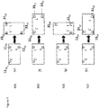
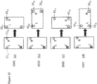
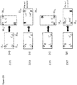
- Example audio output ordering and audio orientation signal generation situations can be shown with respect to Figures 8 to 11 where an example 3 microphone configuration for the capture or recording apparatus is shown and an example 3 speaker configuration for the playback or rendering apparatus is shown for orientation steps of 90°.
- the initial orientation (0 degrees) is in portrait orientation with a first microphone L 11 11 located to the top left of the apparatus, a second microphone R 11 12 located to the top right of the apparatus and a third microphone L' 11 13 located at the bottom left of the apparatus.
- the initial orientation (0 degrees) is in portrait orientation with a first speaker 33 11 located to the top left of the apparatus, a second speaker 33 12 located to the top right of the apparatus and a third speaker 33 13 located at the bottom left of the apparatus.
- Figure 8 shows the four situations where the recording or capture apparatus (sender apparatus) is in initial orientation and the playback or rendering apparatus (receiver apparatus) is rotated with 90 degree granularity (where the rotation is measured clockwise in degrees).
- the microphone order generator can in these four situations be configured to generate an audio output order of L, R, L'.
- the audio outputs are correctly ordered or labelled such that the left(most) channel audio signal is that generated by the first microphone 11 11 L and the right(most) channel audio signal is that generated by the second microphone 11 12 R. It would be understood that in some embodiments the left(most) channel audio signal can be that generated by the third microphone 11 13 L'.
- Figure 8 shows that despite the rotation of the playback apparatus there is no problem in playback and as such in some embodiments there is no need to send AOS data.
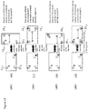
- Figure 9 shows the four situations where the recording or capture apparatus (sender apparatus) is 90 degrees clockwise from the initial orientation and the playback or rendering apparatus (receiver apparatus) is rotated with 90 degree granularity (where the rotation is measured clockwise in degrees).
- the microphone order generator can in these four situations be configured to generate an audio output order of L', L, R.
- the audio outputs are correctly ordered or labelled such that the left(most) channel audio signal is that generated by the third microphone 11 13 L' and the right(most) channel audio signal is that generated by the first microphone 11 11 L. It would be understood that in some embodiments the right(most) channel audio signal can be that generated by the second microphone 11 12 R.
- Figure 9 shows that despite the rotation of the capture apparatus and playback apparatus there is no problem and as such in some embodiments there is no need to send AOS data (provided the audio outputs are correctly ordered or labelled).
- Figure 10 shows the four situations where the recording or capture apparatus (sender apparatus) is 180 degrees clockwise from the initial orientation and the playback or rendering apparatus (receiver apparatus) is rotated with 90 degree granularity (where the rotation is measured clockwise in degrees).
- the microphone order generator can in these four situations be configured to generate an audio output order of R, L, L'.
- the audio outputs are correctly ordered or labelled such that the left(most) channel audio signal is that generated by the second microphone 11 12 R and the right(most) channel audio signal is that generated by the first microphone 11 11 L. It would be understood that in some embodiments the right(most) channel audio signal can be that generated by the third microphone 11 13 L'.
- Figure 10 shows that despite the rotation of the capture apparatus and playback apparatus there is no problem and as such in some embodiments there is no need to send AOS data (provided the audio outputs are correctly ordered or labelled).
- Figure 11 shows the four situations where the recording or capture apparatus (sender apparatus) is 270 degrees clockwise from the initial orientation and the playback or rendering apparatus (receiver apparatus) is rotated with 90 degree granularity (where the rotation is measured clockwise in degrees).
- the microphone order generator can in these four situations be configured to generate an audio output order of L, L', R.
- the audio outputs are correctly ordered or labelled such that the left(most) channel audio signal is that generated by the first microphone 11 11 L and the right(most) channel audio signal is that generated by the third microphone 11 13 L'. It would be understood that in some embodiments the left(most) channel audio signal can be that generated by the second microphone 11 12 R.
- Figure 11 shows that despite the rotation of the capture apparatus and playback apparatus there is no problem and as such in some embodiments there is no need to send AOS data (provided the audio outputs are correctly ordered or labelled).
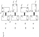
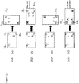
- a further example audio output ordering and audio orientation signal generation situations can be shown with respect to Figures 12 to 15 where an example 2 microphone configuration for the capture or recording apparatus is shown and an example 2 speaker configuration for the playback or rendering apparatus is shown for orientation steps of 90°.
- the initial orientation (0 degrees) is in portrait orientation with a first microphone L 11 11 located to the top left of the apparatus, and a second microphone R 11 12 located to the top right of the apparatus.
- a first microphone L 11 11 located to the top left of the apparatus
- a second microphone R 11 12 located to the top right of the apparatus.
- the initial orientation (0 degrees) is in portrait orientation with a first speaker 33 11 located to the top left of the apparatus and a second speaker 33 12 located to the top right of the apparatus.
- the third speaker 33 13 removed, disabled or switched off.
- Figure 12 for example shows the four situations where the recording or capture apparatus (sender apparatus) is in initial orientation and the playback or rendering apparatus (receiver apparatus) is rotated with 90 degree granularity (where the rotation is measured clockwise in degrees).
- the microphone order generator can in these four situations be configured to generate an audio output order of L, R.
- the audio outputs are correctly ordered or labelled such that the left(most) channel audio signal is that generated by the first microphone 11 11 L and the right(most) channel audio signal is that generated by the second microphone 11 12 R.
- Figure 12 shows that there is no problem in playback caused by the capture apparatus and as such in some embodiments there is no need to send AOS data.
- Figure 13 shows the four situations where the recording or capture apparatus (sender apparatus) is 90 degrees clockwise from the initial orientation and the playback or rendering apparatus (receiver apparatus) is rotated with 90 degree granularity (where the rotation is measured clockwise in degrees).
- the microphone order generator can in these four situations be configured to generate an audio output order of L, R.
- the audio outputs are ordered or labelled such that the left(most) channel audio signal is that generated by the first microphone 11 11 L and the right(most) channel audio signal is that generated by the second microphone 11 12 R.
- the orientation of the recording or capture apparatus is such that there is no or very little horizontal separation between the first microphone 11 11 and second microphone 11 12 and therefore the horizontal stereo capture effect is minimal (below a certain threshold) or there is none.
- Figure 13 therefore shows that the orientation of the capture apparatus can cause a problem and as such AOS data is to be sent to permit the receiving apparatus or playback apparatus to allow for the lack of horizontal separation (or vertical capture).
- the audio output order is to be made based on the orientation indicated by AOS. In other words for the example shown in Figure 13 the audio output order can be based on which microphone is located upmost and which is located downmost on the device (instead of leftmost and rightmost).
- Figure 14 shows the four situations where the recording or capture apparatus (sender apparatus) is 180 degrees clockwise from the initial orientation and the playback or rendering apparatus (receiver apparatus) is rotated with 90 degree granularity (where the rotation is measured clockwise in degrees).
- the microphone order generator can in these four situations be configured to generate an audio output order of R, L.
- the audio outputs are correctly ordered or labelled such that the left(most) channel audio signal is that generated by the second microphone 11 12 R and the right(most) channel audio signal is that generated by the first microphone 11 11 L.
- Figure 14 shows that there is no problem in playback caused by the capture apparatus and as such in some embodiments there is no need to send AOS data (provided the audio outputs are correctly ordered or labelled).
- Figure 15 shows the four situations where the recording or capture apparatus (sender apparatus) is 270 degrees clockwise from the initial orientation and the playback or rendering apparatus (receiver apparatus) is rotated with 90 degree granularity (where the rotation is measured clockwise in degrees).
- the microphone order generator can in these four situations be configured to generate an audio output order of R, L.
- the audio outputs are ordered or labelled such that the left(most) channel audio signal is that generated by the second microphone 11 12 R and the right(most) channel audio signal is that generated by the first microphone 11 11 L.
- the orientation of the recording or capture apparatus is such that there is no or very little horizontal separation between the first microphone 11 11 and second microphone 11 12 and therefore the horizontal stereo capture effect is minimal (below a certain threshold) or there is none.
- Figure 15 therefore shows that the orientation of the capture apparatus can cause a problem and as such AOS data is to be sent to permit the receiving apparatus or playback apparatus to allow for the lack of horizontal separation (or vertical capture).
- the audio output order is to be made based on the orientation indicated by AOS. In other words for the example shown in Figure 15 , the audio output order can be based on which microphone is located upmost and which is located downmost on the device (instead of leftmost and rightmost).
- a further example audio output ordering and audio orientation signal generation situations can be shown with respect to Figures 16 to 19 where an example 2 microphone configuration for the capture or recording apparatus is shown and an example 3 speaker configuration for the playback or rendering apparatus is shown for orientation steps of 90°.
- the initial orientation (0 degrees) is in portrait orientation with a first microphone L 11 11 located to the top left of the apparatus, and a second microphone R 11 12 located to the top right of the apparatus.
- a first microphone L 11 11 located to the top left of the apparatus
- a second microphone R 11 12 located to the top right of the apparatus.
- the example 3 speaker configuration (which is similar to the examples shown in Figures 8 to 11 ) the initial orientation (0 degrees) is in portrait orientation with a first speaker 33 11 located to the top left of the apparatus, a second speaker 33 12 located to the top right of the apparatus and a third speaker 33 13 located at the bottom left of the apparatus.
- Figure 16 shows the four situations where the recording or capture apparatus (sender apparatus) is in initial orientation and the playback or rendering apparatus (receiver apparatus) is rotated with 90 degree granularity (where the rotation is measured clockwise in degrees).
- the microphone order generator can in these four situations be configured to generate an audio output order of L, R.
- the audio outputs are correctly ordered or labelled such that the left(most) channel audio signal is that generated by the first microphone 11 11 L and the right(most) channel audio signal is that generated by the second microphone 11 12 R.
- Figure 12 shows that there is no problem in playback caused by the capture apparatus and as such in some embodiments there is no need to send AOS data.
- Figure 17 shows the four situations where the recording or capture apparatus (sender apparatus) is 90 degrees clockwise from the initial orientation and the playback or rendering apparatus (receiver apparatus) is rotated with 90 degree granularity (where the rotation is measured clockwise in degrees).
- the microphone order generator can in these four situations be configured to generate an audio output order of L, R.
- the audio outputs are ordered or labelled such that the left(most) channel audio signal is that generated by the first microphone 11 11 L and the right(most) channel audio signal is that generated by the second microphone 11 12 R.
- the orientation of the recording or capture apparatus is such that there is no or very little horizontal separation between the first microphone 11 11 and second microphone 11 12 and therefore the horizontal stereo capture effect is minimal (below a certain threshold) or there is none.
- Figure 13 therefore shows that the orientation of the capture apparatus can cause a problem and as such AOS data is to be sent to permit the receiving apparatus or playback apparatus to allow for the lack of horizontal separation (or vertical capture).
- the audio output order can be made based on the orientation indicated by AOS.
- the output order can be based on which microphone is located upmost and which is located downmost on the device (instead of leftmost and rightmost).
- Figure 18 shows the four situations where the recording or capture apparatus (sender apparatus) is 180 degrees clockwise from the initial orientation and the playback or rendering apparatus (receiver apparatus) is rotated with 90 degree granularity (where the rotation is measured clockwise in degrees).
- the microphone order generator can in these four situations be configured to generate an audio output order of R, L.
- the audio outputs are correctly ordered or labelled such that the left(most) channel audio signal is that generated by the second microphone 11 12 R and the right(most) channel audio signal is that generated by the first microphone 11 11 L.
- Figure 18 shows that there is no problem in playback caused by the capture apparatus and as such in some embodiments there is no need to send AOS data (provided the audio outputs are correctly ordered or labelled).
- Figure 19 shows the four situations where the recording or capture apparatus (sender apparatus) is 270 degrees clockwise from the initial orientation and the playback or rendering apparatus (receiver apparatus) is rotated with 90 degree granularity (where the rotation is measured clockwise in degrees).
- the microphone order generator can in these four situations be configured to generate an audio output order of R, L.
- the audio outputs are ordered or labelled such that the left(most) channel audio signal is that generated by the second microphone 11 12 R and the right(most) channel audio signal is that generated by the first microphone 11 11 L.
- the orientation of the recording or capture apparatus is such that there is no or very little horizontal separation between the first microphone 11 11 and second microphone 11 12 and therefore the horizontal stereo capture effect is minimal (below a certain threshold) or there is none.
- Figure 19 therefore shows that the orientation of the capture apparatus can cause a problem and as such AOS data is to be sent to permit the receiving apparatus or playback apparatus to allow for the lack of horizontal separation (or vertical capture).
- the audio output order is to be made based on the orientation indicated by AOS i.e. in the case of this figure it will be based on which microphone is located upmost and which is located downmost on the device (instead of leftmost and rightmost).
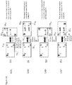
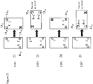
- a fourth example audio output ordering and audio orientation signal generation situations can be shown with respect to Figures 20 to 23 where an example 3 microphone configuration for the capture or recording apparatus is shown and an example 2 speaker configuration for the playback or rendering apparatus is shown for orientation steps of 90°.
- the initial orientation (0 degrees) is in portrait orientation with a first microphone L 11 11 located to the top left of the apparatus, a second microphone R 11 12 located to the top right of the apparatus and a third microphone L' 11 13 located at the bottom left of the apparatus (in other words similar to the configuration as shown in Figures 8 to 11 ).
- the initial orientation (0 degrees) is in portrait orientation with a first speaker L 33 11 located to the top left of the apparatus, and a speaker microphone R 33 12 located to the top right of the apparatus.
- a first speaker L 33 11 located to the top left of the apparatus
- a speaker microphone R 33 12 located to the top right of the apparatus.
- Figure 20 shows the four situations where the recording or capture apparatus (sender apparatus) is in initial orientation and the playback or rendering apparatus (receiver apparatus) is rotated with 90 degree granularity (where the rotation is measured clockwise in degrees).
- the microphone order generator can in these four situations be configured to generate an audio output order of L, R, L'.
- the audio outputs are correctly ordered or labelled such that the left(most) channel audio signal is that generated by the first microphone 11 11 L and the right(most) channel audio signal is that generated by the second microphone 11 12 R. It would be understood that in some embodiments the left(most) channel audio signal can be that generated by the third microphone 11 13 L'.
- Figure 20 shows that there is no problem in playback caused by the capture apparatus and as such in some embodiments there is no need to send AOS data.
- Figure 21 shows the four situations where the recording or capture apparatus (sender apparatus) is 90 degrees clockwise from the initial orientation and the playback or rendering apparatus (receiver apparatus) is rotated with 90 degree granularity (where the rotation is measured clockwise in degrees).
- the microphone order generator can in these four situations be configured to generate an audio output order of L', L, R.
- the audio outputs are correctly ordered or labelled such that the left(most) channel audio signal is that generated by the third microphone 11 13 L' and the right(most) channel audio signal is that generated by the first microphone 11 11 L. It would be understood that in some embodiments the right(most) channel audio signal can be that generated by the second microphone 11 12 R.
- Figure 21 shows that there is no problem in playback caused by the capture apparatus and as such in some embodiments there is no need to send AOS data (provided the audio outputs are correctly ordered or labelled).
- Figure 22 shows the four situations where the recording or capture apparatus (sender apparatus) is 180 degrees clockwise from the initial orientation and the playback or rendering apparatus (receiver apparatus) is rotated with 90 degree granularity (where the rotation is measured clockwise in degrees).
- the microphone order generator can in these four situations be configured to generate an audio output order of R, L, L'.
- the audio outputs are correctly ordered or labelled such that the left(most) channel audio signal is that generated by the second microphone 11 12 R and the right(most) channel audio signal is that generated by the first microphone 11 11 L. It would be understood that in some embodiments the right(most) channel audio signal can be that generated by the third microphone 11 13 L'.
- Figure 22 shows that there is no problem in playback caused by the capture apparatus and as such in some embodiments there is no need to send AOS data (provided the audio outputs are correctly ordered or labelled).
- Figure 23 shows the four situations where the recording or capture apparatus (sender apparatus) is 270 degrees clockwise from the initial orientation and the playback or rendering apparatus (receiver apparatus) is rotated with 90 degree granularity (where the rotation is measured clockwise in degrees).
- the microphone order generator can in these four situations be configured to generate an audio output order of L, L', R.
- the audio outputs are correctly ordered or labelled such that the left(most) channel audio signal is that generated by the first microphone 11 11 L and the right(most) channel audio signal is that generated by the third microphone 11 13 L'. It would be understood that in some embodiments the left(most) channel audio signal can be that generated by the second microphone 11 12 R.
- Figure 13 shows that there is no problem in playback caused by the capture apparatus and as such in some embodiments there is no need to send AOS data (provided the audio outputs are correctly ordered or labelled).
- FIG. 5 an example receiving or playback apparatus is shown according to some embodiments. Furthermore with respect to Figures 6 and 7 example operations of the playback or receiving apparatus as shown in Figure 5 are described.
- the receiving apparatus is configured to receive the AOS input 403.
- the AOS input 403 can in some embodiments be passed to a channel selector 409.
- the apparatus comprises a gravity/orientation sensor 405.
- the gravity/orientation sensor 405 is configured to perform a similar role as the gravity/orientation sensor described in the recording or capture apparatus.
- the gravity/orientation sensor 405 is configured to provide an orientation output to the channel selector 409.
- the playback or receiving apparatus comprises a channel selector 409.
- the channel selector 409 can be configured to receive the AOS input 403, and the gravity/orientation sensor output from the gravity/orientation sensor 405. Furthermore in some embodiments the channel selector 409 can be configured to receive audio input configuration/audio output order information from the capture or recording apparatus.
- the channel selector 409 can be configured to determine from the orientation sensor input value and the AOS input the channel output configurations.
- channel selector 409 is configured to perform this configuration having knowledge of the playback apparatus speaker configuration. In other words with knowledge of when possible problems in playback can occur such as for example what orientation would produce no horizontal separation between speakers.
- the channel selector 409 can further be configured to perform the channel output determination based on the audio input configuration information or audio output order information passed from the capture or recording device. For example where the audio signal input is not arranged in the audio output order but is effectively ordered by the channel selector 409.
- the audio playback apparatus is configured to receive the audio input.
- the audio inputs are shown in Figure 5 as audio input 1 401 1 and audio input X 401 x .
- the audio inputs are passed to the channel mixer/switch 411.
- the receiving or playback apparatus comprises a channel mixer/switch 411.
- the channel mixer/switch 411 can be configured to receive input from the channel selector 409 and mix and/or switch the audio inputs to generate suitable audio outputs. For example as shown in Figure 5 a first audio output 1 413 1 and audio output Y 413 Y .
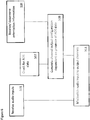
- the operation as shown in Figure 6 differs from that shown in Figure 7 in that the channel selector is configured to generate the channel output configuration dependent on the presence of the AOS data.
- the embodiments as shown in Figure 6 differs from the embodiments in Figure 7 in that the apparatus as represented in the embodiments shown in Figure 6 is configured to generate channel output configuration only when the AOS data is provided where the output configuration is based on a combination of the factors of the received AOS data and the orientation information and otherwise the 'initial' orientation conditions are used in the channel mixer/switch 411.
- the apparatus is configured to receive AOS data at known periods or continuously and as such is configured to determine the channel output configuration based on the AOS data and the orientation information.
- step 509 The operation of generating channel output configurations based dependent on the presence of AOS data is shown in Figure 6 by step 509.
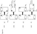
- Example audio input to output configuration situations can be shown with respect to Figures 8 to 11 where an example 3 microphone configuration for the capture or recording apparatus is shown for orientation steps of 90° and an example 3 speaker configuration for the playback or rendering apparatus is shown for orientation steps of 90°.
- FIG. 8 shows that where the capture or recording apparatus and the playback apparatus or receiver both are in initial orientation 701 the left channel audio signal L is output on the first speaker 33 11 and the right channel audio signal R is output on the second speaker 33 12 .
- the playback apparatus or receiver is rotated by 90 degrees 703 the left channel audio signal L is output on the third speaker 33 13 and the right channel audio signal R is output on the first speaker 33 11 .
- the playback apparatus or receiver is rotated by 180 degrees 705 the left channel audio signal L is output on the second speaker 33 12 and the right channel audio signal R is output on the first speaker 33 11 .
- the playback apparatus or receiver is rotated by 270 degrees 707 the left channel audio signal L is output on the first speaker 33 11 and the right channel audio signal R is output on the third speaker 33 13 .
- Figure 9 shows that where the recording or capture apparatus has been rotated by 90 degrees clockwise from the initial position and where the playback apparatus or receiver is in initial orientation 801 the left channel audio signal L' is output on the first speaker 33 11 and the right channel audio signal L is output on the second speaker 33 12 .
- the playback apparatus or receiver is rotated by 90 degrees 803 the left channel audio signal L' is output on the third speaker 33 13 and the right channel audio signal L is output on the first speaker 33 11 .
- the playback apparatus or receiver is rotated by 180 degrees 805 the left channel audio signal L' is output on the second speaker 33 12 and the right channel audio signal L is output on the first speaker 33 11 .
- the playback apparatus or receiver is rotated by 270 degrees 807 the left channel audio signal L' is output on the first speaker 33 11 and the right channel audio signal L is output on the third speaker 33 13 .
- Figure 10 shows that where the recording or capture apparatus has been rotated by 180 degrees clockwise from the initial position and where the playback apparatus or receiver is in initial orientation 901 the left channel audio signal R is output on the first speaker 33 11 and the right channel audio signal L is output on the second speaker 33 12 .
- the playback apparatus or receiver is rotated by 90 degrees 903 the left channel audio signal R is output on the third speaker 33 13 and the right channel audio signal L is output on the first speaker 33 11 .
- the playback apparatus or receiver is rotated by 180 degrees 905 the left channel audio signal R is output on the second speaker 33 12 and the right channel audio signal L is output on the first speaker 33 11 .
- the playback apparatus or receiver is rotated by 270 degrees 907 the left channel audio signal R is output on the first speaker 33 11 and the right channel audio signal L is output on the third speaker 33 13 .
- Figure 11 shows that where the recording or capture apparatus has been rotated by 270 degrees clockwise from the initial position and where the playback apparatus or receiver is in initial orientation 1001 the left channel audio signal L is output on the first speaker 33 11 and the right channel audio signal L' is output on the second speaker 33 12 .
- the playback apparatus or receiver is rotated by 90 degrees 1003 the left channel audio signal L is output on the third speaker 33 13 and the right channel audio signal L' is output on the first speaker 33 11 .
- the playback apparatus or receiver is rotated by 180 degrees 1005 the left channel audio signal L is output on the second speaker 33 12 and the right channel audio signal L' is output on the first speaker 33 11 .
- the playback apparatus or receiver is rotated by 270 degrees 1007 the left channel audio signal L is output on the first speaker 33 11 and the right channel audio signal L' is output on the third speaker 33 13 .
- a further example audio input to output configuration situations can be shown with respect to Figures 12 to 15 where an example 2 microphone configuration for the capture or recording apparatus is shown for orientation steps of 90° and an example 2 speaker configuration for the playback or rendering apparatus is shown for orientation steps of 90°.
- Figure 12 shows that where the capture or recording apparatus and the playback apparatus or receiver both are in initial orientation 1101 the left channel audio signal L is output on the first speaker 33 11 and the right channel audio signal R is output on the second speaker 33 12 .
- the playback apparatus or receiver is rotated by 90 degrees 1103 the orientation of the playback apparatus is such that there is no horizontal separation between the first speaker 33 11 and second speaker 33 12 and therefore only a mono mixed version of the combined left channel audio signal L and right channel audio signal R (L+R) is output on both the first speaker 33 11 and second speaker 33 12 .
- the playback apparatus or receiver is rotated by 180 degrees 1105 the left channel audio signal L is output on the second speaker 33 12 and the right channel audio signal R is output on the first speaker 33 11 .
- the orientation of the playback apparatus is such that there is no horizontal separation between the first speaker 33 11 and second speaker 33 12 and therefore only a mono mixed version of the combined left channel audio signal L and right channel audio signal R (L+R) is output on both the first speaker 33 11 and second speaker 33 12 .
- FIG. 13 shows that where the recording or capture apparatus has been rotated by 90 degrees clockwise from the initial position and where the playback apparatus or receiver is in initial orientation 1201 the AOS data causes a mono mixed version of the combined left channel audio signal L and right channel audio signal R (L+R) to be output on both the first speaker 33 11 and second speaker 33 12 .
- the playback apparatus or receiver treats the received signals (in this example figure and in other example figures below) as captured by microphones positioned vertically with respect to each other.
- the AOS data causes the left channel audio signal L to be output on the first speaker 33 11 and the right channel audio signal R to be output on the second speaker 33 12 .
- the receiver is configured to output the received audio signals as a vertical stereo output.
- the AOS data causes a mono mixed version of the combined left channel audio signal L and right channel audio signal R (L+R) to be output on both the first speaker 33 11 and second speaker 33 12 .
- the AOS data causes the left channel audio signal L to be output on the second speaker 33 12 and the right channel audio signal R to be output on the first speaker 33 11 and therefore to output the received audio signals as a vertical stereo output.
- Figure 14 shows that where the recording or capture apparatus has been rotated by 180 degrees clockwise from the initial position and where the playback apparatus or receiver is in initial orientation 1301 the left channel audio signal R is output on the first speaker 33 11 and the right channel audio signal L is output on the second speaker 33 12 .
- the orientation of the playback apparatus is such that there is no horizontal separation between the first speaker 33 11 and second speaker 33 12 and therefore only a mono mixed version of the combined left channel audio signal R and right channel audio signal L (L+R) is output on both the first speaker 33 11 and second speaker 33 12 .
- the playback apparatus or receiver is rotated by 180 degrees 1305 the left channel audio signal R is output on the second speaker 33 12 and the right channel audio signal L is output on the first speaker 33 11 . Furthermore where the playback apparatus or receiver is rotated by 270 degrees 1307 the orientation of the playback apparatus is such that there is no horizontal separation between the first speaker 33 11 and second speaker 33 12 and therefore only a mono mixed version of the combined left channel audio signal R and right channel audio signal L (L+R) is output on both the first speaker 33 11 and second speaker 33 12 .
- FIG. 15 shows that where the recording or capture apparatus has been rotated by 270 degrees clockwise from the initial position and where the playback apparatus or receiver is in initial orientation 1401 the AOS data causes a mono mixed version of the combined left channel audio signal R and right channel audio signal L (L+R) to be output on both the first speaker 33 11 and second speaker 33 12 .
- the AOS data causes the left channel audio signal R to be output on the first speaker 33 11 and the right channel audio signal L to be output on the second speaker 33 12 .
- the receiver is configured to output the received audio signals as a vertical stereo output.
- the AOS data causes a mono mixed version of the combined left channel audio signal R and right channel audio signal L (L+R) to be output on both the first speaker 33 11 and second speaker 33 12 .
- the AOS data causes the left channel audio signal R to be output on the second speaker 33 12 and the right channel audio signal L to be output on the first speaker 33 11 the left channel audio signal L' is output on the first speaker 33 11 and therefore to output the received audio signals as a vertical stereo output.
- a further example audio input to output configuration situations can be shown with respect to Figures 16 to 19 where an example 2 microphone configuration for the capture or recording apparatus is shown for orientation steps of 90° and an example 3 speaker configuration for the playback or rendering apparatus is shown for orientation steps of 90°.
- Figure 16 shows that where the capture or recording apparatus and the playback apparatus or receiver both are in initial orientation 1501 the left channel audio signal L is output on the first speaker 33 11 and the right channel audio signal R is output on the second speaker 33 12 .
- the playback apparatus or receiver is rotated by 90 degrees 1503 the left channel audio signal L is output on the third speaker 33 13 and the right channel audio signal R is output on the first speaker 33 11 .
- the playback apparatus or receiver is rotated by 180 degrees 1505 the left channel audio signal L is output on the second speaker 33 12 and the right channel audio signal R is output on the first speaker 33 11 .
- the playback apparatus or receiver is rotated by 270 degrees 1507 the left channel audio signal L is output on the first speaker 33 11 and the right channel audio signal R is output on the third speaker 33 13 .
- FIG. 17 shows that where the recording or capture apparatus has been rotated by 90 degrees clockwise from the initial position and where the playback apparatus or receiver is in initial orientation 1601 the AOS data causes the left channel audio signal L to be output on the first speaker 33 11 and the right channel audio signal R to be output on the third speaker 33 13 .
- the receiver is configured to output the received audio signals as a vertical stereo output and produce a better quality output.
- the playback apparatus or receiver is rotated by 90 degrees 1603 the AOS data causes the left channel audio signal L to be output on the first speaker 33 11 and the right channel audio signal R to be output on the second speaker 33 12 . Therefore the receiver is configured to output the received audio signals as an improved quality vertical stereo output.
- the AOS data causes the left channel audio signal L to be output on the third speaker 33 13 and the right channel audio signal R to be output on the first speaker 33 11 .
- the receiver is also configured to output the received audio signals as a vertical stereo output and produce a better quality output.
- the AOS data causes the left channel audio signal L to be output on the second speaker 33 12 and the right channel audio signal R to be output on the first speaker 33 11 and therefore to output the received audio signals as a vertical stereo output.
- Figure 18 shows that where the recording or capture apparatus has been rotated by 180 degrees clockwise from the initial position and where the playback apparatus or receiver is in initial orientation 1701 the left channel audio signal R is output on the first speaker 33 11 and the right channel audio signal L is output on the second speaker 33 12 .
- the playback apparatus or receiver is rotated by 90 degrees 1703 the left channel audio signal R is output on the third speaker 33 13 and the right channel audio signal L is output on the first speaker 33 11 .
- the playback apparatus or receiver is rotated by 180 degrees 1705 the left channel audio signal R is output on the second speaker 33 12 and the right channel audio signal L is output on the first speaker 33 11 .
- the playback apparatus or receiver is rotated by 270 degrees 1707 the left channel audio signal R is output on the first speaker 33 11 and the right channel audio signal L is output on the third speaker 33 13 .
- FIG. 19 shows that where the recording or capture apparatus has been rotated by 270 degrees clockwise from the initial position and where the playback apparatus or receiver is in initial orientation 1801 the AOS data causes the left channel audio signal R to be output on the first speaker 33 11 and the right channel audio signal L to be output on the third speaker 33 13 .
- the receiver is configured to output the received audio signals as a vertical stereo output and produce a better quality output.
- the playback apparatus or receiver is rotated by 90 degrees 1803 the AOS data causes the left channel audio signal R to be output on the first speaker 33 11 and the right channel audio signal L to be output on the second speaker 33 12 . Therefore the receiver is configured to output the received audio signals as an improved quality vertical stereo output.
- the AOS data causes the left channel audio signal R to be output on the third speaker 33 13 and the right channel audio signal L to be output on the first speaker 33 11 .
- the receiver is also configured to output the received audio signals as a vertical stereo output and produce a better quality output.
- the AOS data causes the left channel audio signal R to be output on the second speaker 33 12 and the right channel audio signal L to be output on the first speaker 33 11 and therefore to output the received audio signals as a vertical stereo output.
- the fourth example audio input to output configuration situations can be shown with respect to Figures 20 to 23 where an example 3 microphone configuration for the capture or recording apparatus is shown for orientation steps of 90° and an example 2 speaker configuration for the playback or rendering apparatus is shown for orientation steps of 90°.
- FIG. 20 shows that where the capture or recording apparatus and playback apparatus or receiver both are in initial orientation 1901 the left channel audio signal L is output on the first speaker 33 11 and the right channel audio signal R is output on the second speaker 33 12 .
- the orientation of the playback apparatus is such that there is no horizontal separation between the first speaker 33 11 and second speaker 33 12 and therefore only a mono mixed version of the combined left channel audio signal L and right channel audio signal R (L+R) is output on both the first speaker 33 11 and second speaker 33 12 . In other words a mono mixed output is provided.
- the playback apparatus or receiver is rotated by 180 degrees 1905 the left channel audio signal L is output on the second speaker 33 12 and the right channel audio signal R is output on the first speaker 33 11 . Furthermore where the playback apparatus or receiver is rotated by 270 degrees 1907 the orientation of the playback apparatus is also such that there is no horizontal separation between the first speaker 33 11 and second speaker 33 12 and therefore only a mono mixed version of the combined left channel audio signal L and right channel audio signal R (L+R) is output on both the first speaker 33 11 and second speaker 33 12 .
- Figure 21 shows that where the recording or capture apparatus has been rotated by 90 degrees clockwise from the initial position and where the playback apparatus or receiver is in initial orientation 2001 the left channel audio signal L' is output on the first speaker 33 11 and the right channel audio signal L is output on the second speaker 33 12 .
- the orientation of the playback apparatus is such that there is no horizontal separation between the first speaker 33 11 and second speaker 33 12 and therefore only a mono mixed version of the combined left channel audio signal L' and right channel audio signal L (L+L') is output on both the first speaker 33 11 and second speaker 33 12 .
- the playback apparatus or receiver is rotated by 180 degrees 2005 the left channel audio signal L' is output on the second speaker 33 12 and the right channel audio signal L is output on the first speaker 33 11 . Furthermore where the playback apparatus or receiver is rotated by 270 degrees 2007 the orientation of the playback apparatus is such that there is no horizontal separation between the first speaker 33 11 and second speaker 33 12 and therefore only a mono mixed version of the combined left channel audio signal L' and right channel audio signal L (L+L') is output on both the first speaker 33 11 and second speaker 33 12 .
- Figure 22 shows that where the recording or capture apparatus has been rotated by 180 degrees clockwise from the initial position and where the playback apparatus or receiver is in initial orientation 2101 the left channel audio signal R is output on the first speaker 33 11 and the right channel audio signal L is output on the second speaker 33 12 .
- the orientation of the playback apparatus is such that there is no horizontal separation between the first speaker 33 11 and second speaker 33 12 and therefore only a mono mixed version of the combined left channel audio signal R and right channel audio signal L (R+L) is output on both the first speaker 33 11 and second speaker 33 12 .
- the playback apparatus or receiver is rotated by 180 degrees 2105 the left channel audio signal R is output on the second speaker 33 12 and the right channel audio signal L is output on the first speaker 33 11 . Furthermore where the playback apparatus or receiver is rotated by 270 degrees 2107 the orientation of the playback apparatus is such that there is no horizontal separation between the first speaker 33 11 and second speaker 33 12 and therefore only a mono mixed version of the combined left channel audio signal R and right channel audio signal L (R+L) is output on both the first speaker 33 11 and second speaker 33 12 .
- Figure 23 shows that where the recording or capture apparatus has been rotated by 270 degrees clockwise from the initial position and where the playback apparatus or receiver is in initial orientation 2201 the left channel audio signal L is output on the first speaker 33 11 and the right channel audio signal L' is output on the second speaker 33 12 .
- the orientation of the playback apparatus is such that there is no horizontal separation between the first speaker 33 11 and second speaker 33 12 and therefore only a mono mixed version of the combined left channel audio signal L and right channel audio signal L' (L+L') is output on both the first speaker 33 11 and second speaker 33 12 .
- the playback apparatus or receiver is rotated by 180 degrees 2205 the left channel audio signal L is output on the second speaker 33 12 and the right channel audio signal L' is output on the first speaker 33 11 . Furthermore where the playback apparatus or receiver is rotated by 270 degrees 2207 the orientation of the playback apparatus is such that there is no horizontal separation between the first speaker 33 11 and second speaker 33 12 and therefore only a mono mixed version of the combined left channel audio signal L and right channel audio signal L' (L+L') is output on both the first speaker 33 11 and second speaker 33 12 .
- the capturing device may be rotated in several subsequent rotations and each rotation may change the orientation of the audio capture, first from the initial orientation to a new orientation and then later from the new orientation to a further new orientation.
- the disclosed method may be applied for each rotation to ensure that audio playback orientation is aligned with the recording orientation.
- the capture device can determine a difference in orientation from a determined orientation and an earlier orientation.
- the earlier orientation can be an initial orientation.
- system apparatus are configured to detect the orientation of audio capture (xxx degrees) in the sending device as shown in Figure 26 in step 2501
- the recording or capture apparatus in some embodiments is configured to send the orientation of audio capture (xxx degrees) to the receiving device with suitable granularity (and based on the accuracy of the gravitation detector in the recording apparatus). This is shown in Figure 26 in step 2503.
- the playback within the receiving apparatus is configured to use the speakers best corresponding to the orientation of the audio capture. If suitably oriented speakers are not available, then a fall-back from stereo to mono or from surround sound to stereo playback is generated. This is shown in Figure 26 by step 2505.
- the sending or recording apparatus is configured to determine or detect the orientation of audio capture (defined as either vertical or horizontal) within the sending apparatus.
- the recording apparatus orientation determination is shown in Figure 27 by step 2601.
- the sending apparatus can then in some embodiments send the orientation of audio capture (vertical or horizontal) to the receiving or playback apparatus.
- the operation of sending the orientation of audio capture is shown in Figure 27 by step 2603.
- the playback of the audio signals in the receiving apparatus is configured such that the playback apparatus uses the speakers best corresponding to the orientation of the audio capture. If suitably oriented speakers are not available, then the playback apparatus can be configured to fall-back from stereo to mono. In other words for
- capturing and rendering devices are synchronised to use the same audio output order.
- both the capturing and the rendering devices are configured to know which signal is sent first in horizontal capture (for example is the audio output order "left, right” or “right, left") and in vertical capture (for example is the audio output order: "top, bottom” or “bottom, top”).
- the synchronisation information is required to prevent the audio playback having the possibility of an error of 180 degrees.
- Table I shows examples of the application of the embodiments shown in Figure 27 describing the relationship between capture device orientation, audio (capture) orientation and audio output order for some of the examples illustrated in the Figures.
- the audio orientation is signalled via AOS from the sending device to the receiving device when deviation from the default (horizontal orientation in this example embodiment) occurs.
- audio orientation is signalled via AOS from the sending device to the receiving device for the cases marked with star (*) in the Table.
- Audio output order is also made known to both the sending and receiving device, for example by also it being sent from the sending device to the receiving device.
- Table I Example of the relationship between capture device orientation, audio (capture) orientation and audio output order.
- sending two (monophonic) audio signals from the capturing device to the receiving or rendering device is sufficient for reproducing stereo (for vertical and horizontal orientation), and therefore knowledge of the two first components in the audio output order is sufficient and reflected by the third component being shown inside brackets in the table.
- the sending device has only two microphones (shown in Figures 12-15 ). In these cases the audio output order can be signalled with only one bit.
- the sending (recording or capture) apparatus is configured to determine or detect the orientation of audio capture (0, 90, 180, or 270 degrees) in the sending apparatus.
- the detecting of the orientation is shown in Figure 28 by step 2701.
- the sending apparatus can be configured to send the orientation of audio capture (0, 90, 180, or 270 degrees) to the receiving apparatus via AOS.
- the operation of sending the orientation information is shown in Figure 28 by step 2703.
- the receiving device is configured to playback the audio signal and further configured to use the speakers best corresponding to the orientation of the audio capture. If suitably oriented speakers are not available then the receiving apparatus is configured to fall-back from stereo to mono or from surround sound to stereo play out or in general to downmixing audio from multi channels to fewer channels. This can be shown as the following operations
- the audio output order within horizontal and vertical capture can be included into the above (2 bit) AOS signalling via the choice of 0 vs. 180 degrees for horizontal capture and 90 vs. 270 degrees for vertical capture.
- the audio output order for the two signals forming stereo is signalled by the AOS data.
- the compact signalling requires that the capturing device (where the capturing device has more than 2 microphones) only sends the two signals sufficient for producing stereo (in other words in the case where there are three microphones the capturing device drops the signals shown inside brackets in Table I from the bit-stream from being sent to the receiving device).
- Table II shows examples of the application of the embodiments shown in Figure 28 of the relationship between capture device orientation and audio (capture) orientation. Audio orientation in such embodiments is sent via AOS when deviation from the default (horizontal non-reversed orientation in this example embodiment) occurs. In other words the audio orientation is sent in the cases marked with star (*) in the following table. Table II: Example of the relationship between capture device orientation and audio (capture) orientation. Case Orientation of capture apparatus Audio (capture) orientation (signalled via AOS) Fig. 8 0 degrees Horizontal Fig. 9 90 degrees Horizontal Fig. 10 180 degrees Horizontal reversed * Fig. 11 270 degrees Horizontal reversed * Fig. 12 0 degrees Horizontal Fig. 13 90 degrees Vertical * Fig. 14 180 degrees Horizontal reversed * Fig. 15 270 degrees Vertical reversed *
- a particular audio capture orientation (for example horizontal audio capture orientation) can be preferred.
- the preferred audio capture orientation can be used (in other words signalled by AOS) even though the audio capture orientation is closer to another orientation.
- a horizontal audio capture orientation can be used (in other words signalled via AOS) even though the difference from horizontal orientation exceeds 45 degrees.
- the receiving device may use for play out the closest orientation it supports (possibly with preference for a certain orientation such as horizontal), in some embodiments the receiving device can further prefer a specific output format, for example stereo playout, rather than switching to play the signal as mono, or in some embodiments the receiving device may simultaneously play out the audio signal from more than one speaker with suitable scaling applied for the playout for each speaker making the audio signal to appear as coming from between the speakers (i.e. from orientations between the speakers).
- the speakers can comprise any suitable audio transducer output device including loudspeakers; headphones; headsets; earpieces; external loudspeakers; and integrated hands free speakers.
- user equipment is intended to cover any suitable type of wireless user equipment, such as mobile telephones, portable data processing devices or portable web browsers, as well as wearable devices.
- the various embodiments of the invention may be implemented in hardware or special purpose circuits, software, logic or any combination thereof.
- some aspects may be implemented in hardware, while other aspects may be implemented in firmware or software which may be executed by a controller, microprocessor or other computing device, although the invention is not limited thereto.
- firmware or software which may be executed by a controller, microprocessor or other computing device, although the invention is not limited thereto.
- While various aspects of the invention may be illustrated and described as block diagrams, flow charts, or using some other pictorial representation, it is well understood that these blocks, apparatus, systems, techniques or methods described herein may be implemented in, as non-limiting examples, hardware, software, firmware, special purpose circuits or logic, general purpose hardware or controller or other computing devices, or some combination thereof.
- the embodiments of this invention may be implemented by computer software executable by a data processor of the mobile device, such as in the processor entity, or by hardware, or by a combination of software and hardware.
- any blocks of the logic flow as in the Figures may represent program steps, or interconnected logic circuits, blocks and functions, or a combination of program steps and logic circuits, blocks and functions.
- the software may be stored on such physical media as memory chips, or memory blocks implemented within the processor, magnetic media such as hard disk or floppy disks, and optical media such as for example DVD and the data variants thereof, CD.
- the memory may be of any type suitable to the local technical environment and may be implemented using any suitable data storage technology, such as semiconductor-based memory devices, magnetic memory devices and systems, optical memory devices and systems, fixed memory and removable memory.
- the data processors may be of any type suitable to the local technical environment, and may include one or more of general purpose computers, special purpose computers, microprocessors, digital signal processors (DSPs), application specific integrated circuits (ASIC), gate level circuits and processors based on multi-core processor architecture, as non-limiting examples.
- Embodiments of the inventions may be practiced in various components such as integrated circuit modules.
- the design of integrated circuits is by and large a highly automated process.
- Complex and powerful software tools are available for converting a logic level design into a semiconductor circuit design ready to be etched and formed on a semiconductor substrate.
- Programs such as those provided by Synopsys, Inc. of Mountain View, California and Cadence Design, of San Jose, California automatically route conductors and locate components on a semiconductor chip using well established rules of design as well as libraries of pre-stored design modules.
- the resultant design in a standardized electronic format (e.g., Opus, GDSII, or the like) may be transmitted to a semiconductor fabrication facility or "fab" for fabrication.
Description
- The present application relates to apparatus for audio recording and playback. The invention further relates to, but is not limited to, apparatus for audio recording and playback within mobile devices.
- Spatial audio signals are being used in greater frequency to produce a more immersive audio experience. A stereo or multi-channel recording can be passed from the recording or capture apparatus to a listening apparatus and replayed using a suitable multi-channel output such as a multi-channel loudspeaker arrangement and with virtual surround processing a pair of stereo headphones or headset.
- It would be understood that in the near future it will be possible for mobile apparatus such as mobile phones to have more than two microphones. This offers the possibility to record real multichannel audio. Similarly it will be possible for mobile apparatus such as mobile phones to have more than two speakers. Thus stereophonic and surround sound audio can be reproduced in mobile devices (such as smartphones).
- In other words it is or will shortly be possible that mobile devices will have the capacity to record (or capture) and play back stereophonic and surround sound audio. Thus mobile devices will also be capable of passing these audio signals from device to device and as such can employ stereophonic and surround sound audio in telecommunication applications and also for other services such as streaming, broadcasting and multicasting when the audio recording or capture has been performed by a suitable or capable mobile device.
-
EP2760223A1 describes a method for encoding a sound field. -
WO2012/061151A1 describes for orientation-sensitive selection and/or preservation of a recording direction using a multi-microphone -
EP1124175A2 describes an apparatus comprising an orientation sensitive user interface mechanism. -
WO2012/061149A1 describes a method for three-dimensional sound recording and reproduction using a multi-microphone setup - HERRE JURGEN ET AL "Interactive teleconferencing Combining Spatial Audio Object Coding and DirAc Technology" describes a DirAC to SAOC parameter transcoder.
- According to a first aspect, there is provided an apparatus according to
claim 1. - According to a second aspect, there is provided an apparatus according to
claim 3. - According to a third aspect, there is provided a method according to claim 6.
- According to a fourth aspect, there is provided a method according to claim 8.
- A computer program product stored on a medium may cause an apparatus to perform the method as described herein.
- An electronic device may comprise apparatus as described herein.
- A chipset may comprise apparatus as described herein.
- Embodiments of the present application aim to address problems associated with the state of the art.
- For better understanding of the present application, reference will now be made by way of example to the accompanying drawings in which:
-
Figure 1 shows schematically an apparatus suitable for being employed in some embodiments; -
Figure 2 shows schematically an example audio capture or recording apparatus according to some embodiments; -
Figure 3 shows schematically a flow diagram of the operation of the audio capture or recording apparatus shown inFigure 2 according to some embodiments; -
Figure 4 shows schematically a further flow diagram of further operations of the audio capture or recording apparatus shown inFigure 2 according to some embodiments; -
Figure 5 shows schematically an example audio playback apparatus according to some embodiments; -
Figure 6 shows schematically a flow diagram of the operation of the audio playback apparatus shown inFigure 5 according to some embodiments; -
Figure 7 shows schematically a further flow diagram of further operations of the audio playback apparatus shown inFigure 5 according to some embodiments; -
Figures 8 to 11 show example 3 microphone capture apparatus and 3 speaker playback apparatus orientation combinations for 90 degree rotations according to some embodiments; -
Figures 12 to 15 show example 2 microphone capture apparatus and 2 speaker playback apparatus orientation combinations for 90 degree rotations according to some embodiments; -
Figures 16 to 19 show example 2 microphone capture apparatus and 3 speaker playback apparatus orientation combinations for 90 degree rotations according to some embodiments; -
Figures 20 to 23 show example 3 microphone capture apparatus and 2 speaker playback apparatus orientation combinations for 90 degree rotations according to some embodiments; -
Figure 24 shows schematically an example 8 microphone capture apparatus and an example 8 speaker playback apparatus configuration according to some embodiments; -
Figure 25 shows schematically an example 3 microphone capture apparatus configuration according to some embodiments; -
Figure 26 shows schematically a flow diagram of the operation of audio recording and playback systems with arbitrary orientation sensing according to some embodiments; -
Figure 27 shows schematically a further flow diagram of the operation of audio recording and playback systems with horizontal and vertical orientation sensing according to some embodiments; and -
Figure 28 shows schematically a flow diagram of the operation of audio recording and playback systems with quartile orientation sensing according to some embodiments. - The following describes in further detail suitable apparatus and possible mechanisms for the provision of effective sound-field recording and playback for example within audio-video capture and playback apparatus operating over a wireless communications link. In the following examples audio capture and playback is described. However it would be appreciated that in some embodiments the audio capture and playback part of an audio-video system.
- As described herein mobile devices or apparatus are more commonly being equipped with multiple microphone configurations or microphone arrays suitable for recording or capturing the audio environment or audio scene surrounding the mobile device or apparatus. A multiple microphone configuration enables the recording of stereo or surround sound signals.
- However such mobile devices or apparatus (such as smart phones) are limited in both the number of microphones and their location. As additional microphones increase size and manufacturing cost microphones current designs 're-use' microphones for different applications. For instance, microphone locations at the 'bottom' and 'top' ends can be employed to pick up speech and reference noise in the hand-portable telephone application of the phone and these microphones reused in video/audio recording applications.
- Similarly mobile devices or apparatus are more commonly being equipped with multiple speaker configurations suitable for generating a suitable audio environment or audio scene in stereo or multichannel audio formats. However such mobile devices or apparatus (such as smart phones) are also limited in both the number of microphones and their location. There are similar constraints to those for microphones as additional speakers increase size and manufacturing cost.
- Therefore when a mobile device is used for capturing audio, the orientation of the device has a significant impact on the quality of the captured audio. For example a stereophonic capable device only able to capture stereophonic audio in one orientation relative to the phone (such as horizontal or vertical orientation due to the location of the microphones) will mean that changing the orientation of the device will also change the 'orientation' of the captured stereophonic audio signal.
- For example when capturing video and audio (e.g. during video-telephony calls) the user may sometimes prefer capturing video in portrait orientation and sometimes in landscape orientation, and change between these even during the same call. This can cause issues when the playback or rendering device is unaware of the orientation of the audio capture device and may prevent the correct playback of the stereophonic audio signal. This can therefore reduce the audio quality at the receiving end.
- There have been suggested solutions for signaling the orientation of a video capturing device during video capture to guarantee that the captured video image is played in a correct orientation at the receiver during the call without the receiving party needing to manually rotate the playback device to match the capturing device. Furthermore rotating the captured video into a new orientation at the playback device or at receiver side is a relatively simple task since all of the information needed for the rotation exists in the captured video signal. However, the capture/rendering of audio is typically limited to certain orientation (due to the limited number of microphones/speakers and their restricted positions on the device) and may not therefore enable "free" rotation of the captured audio signal at the playback device.
- Furthermore the correction of video orientation in future devices using the GSMA Rich Communications Suite (RCS) 5.1 does not properly correct the audio orientation (i.e. the orientation of the captured audio signal) and can make the situation worse since the correction methods proposed may result into the audio and video orientations being out of synchronization (for example a sound source shown at the top of the screen being played out from a speaker located at the right or left hand side of the screen, or the sound source at the left hand side of the screen being played out from the right hand side of the screen).
- Thus the concept as described herein in further detail is one which the audio recording system provides optimal pick up and stereo imaging for the desired recording distance whilst minimizing the number of microphones and taking into account limitations in microphone positioning.
- The concept as described in further detail herein is to provide a solution to align the use of speakers of the playback or rendering (receiving) device (or headphones or external loudspeakers) to the use of microphones in the recording or capturing (sending) device.
- This is achieved in some embodiments by signaling the orientation of audio recording (capture) from the sending device to the receiving device. The signaling in some embodiments can be performed as part of the audio data and sent throughout the transmission or as additional information sent only when the orientation of audio capture changes or when audio capture is performed at non-default orientation (such as vertical capture for stereophonic audio).
- In some embodiments as described in further detail herein the concept extends to apparatus and methods for providing the best possible audio quality at the rendering device when misalignment of audio orientation occurs between the capturing and rendering devices.
- It would be understood that as described herein the orientation of the audio capture device (at the sending side) is detected by using a gravity sensor and by having knowledge of the audio capture properties of the device (in other words the number of the microphones and their positions together with knowledge about which microphones are used for which device orientation). In some embodiments the inclusion of signaling audio orientation can be performed by using Real Time Protocol (RTP) header extension.
- In this regard reference is first made to
Figure 1 which shows a schematic block diagram of an exemplary apparatus orelectronic device 10, which may be used to record (or operate as a capture apparatus) or playback (or operate as a rendering apparatus) audio signals. - The
electronic device 10 may for example be a mobile terminal or user equipment of a wireless communication system when functioning as the recording apparatus or listening apparatus. In some embodiments the apparatus can be an audio player or audio recorder, such as an MP3 player, a media recorder/player (also known as an MP4 player), or any suitable portable apparatus suitable for recording audio or audio/video camcorder/memory audio or video recorder. - The
apparatus 10 can in some embodiments comprise an audio-video subsystem. The audio-video subsystem for example can comprise in some embodiments a microphone or array ofmicrophones 11 for audio signal capture. In some embodiments the microphone or array of microphones can be a solid state microphone, in other words capable of capturing audio signals and outputting a suitable digital format signal in other words not requiring an analogue-to-digital converter. In some other embodiments the microphone or array ofmicrophones 11 can comprise any suitable microphone or audio capture means, for example a condenser microphone, capacitor microphone, electrostatic microphone, electret condenser microphone, dynamic microphone, ribbon microphone, carbon microphone, piezoelectric microphone, or micro electrical-mechanical system (MEMS) microphone. Themicrophone 11 or array of microphones can in some embodiments output the audio captured signal to an analogue-to-digital converter (ADC) 14. - In some embodiments the apparatus can further comprise an analogue-to-digital converter (ADC) 14 configured to receive the analogue captured audio signal from the microphones and outputting the audio captured signal in a suitable digital form. The analogue-to-
digital converter 14 can be any suitable analogue-to-digital conversion or processing means, In some embodiments where the microphones are 'integrated' microphones the microphones contain both audio signal generating and analogue-to-digital conversion capability. - In some embodiments the
apparatus 10 audio-video subsystem further comprises a digital-to-analogue converter 32 for converting digital audio signals from aprocessor 21 to a suitable analogue format. The digital-to-analogue converter (DAC) or signal processing means 32 can in some embodiments be any suitable DAC technology. - Furthermore the audio-video subsystem can comprise in some embodiments a
speaker 33. Thespeaker 33 can in some embodiments receive the output from the digital-to-analogue converter 32 and present the analogue audio signal to the user. In some embodiments thespeaker 33 can be representative of multi-speaker arrangement, a headset, for example a set of headphones, or cordless headphones. - In some embodiments the apparatus audio-video subsystem comprises a
camera 51 or image capturing means configured to supply to theprocessor 21 image data. In some embodiments the camera can be configured to supply multiple images over time to provide a video stream. - In some embodiments the apparatus audio-video subsystem comprises a
display 52. The display or image display means can be configured to output visual images which can be viewed by the user of the apparatus. In some embodiments the display can be a touch screen display suitable for supplying input data to the apparatus. The display can be any suitable display technology, for example the display can be implemented by a flat panel comprising cells of LCD, LED, OLED, or 'plasma' display implementations. - Although the
apparatus 10 is shown having both audio/video capture and audio/video presentation components, it would be understood that in some embodiments theapparatus 10 can comprise only the audio capture or audio presentation parts of the audio subsystem such that in some embodiments of the apparatus the microphone (for audio capture) or the speaker (for audio playback or presentation) are present. - In some embodiments the
apparatus 10 comprises aprocessor 21. Theprocessor 21 is coupled to the audio-video subsystem and specifically in some examples the analogue-to-digital converter 14 for receiving digital signals representing audio signals from themicrophone 11, the digital-to-analogue converter (DAC) 12 configured to output processed digital audio signals, thecamera 51 for receiving digital signals representing video signals, and thedisplay 52 configured to output processed digital video signals from theprocessor 21. - The
processor 21 can be configured to execute various program codes. The implemented program codes can comprise for example audio recording and audio presentation routines according to some embodiments as described herein. In some embodiments the program codes can be configured to perform audio signal processing. - In some embodiments the apparatus further comprises a
memory 22. In some embodiments the processor is coupled tomemory 22. The memory can be any suitable storage means. In some embodiments thememory 22 comprises aprogram code section 23 for storing program codes implementable upon theprocessor 21. Furthermore in some embodiments thememory 22 can further comprise a storeddata section 24 for storing data, for example data that has been encoded in accordance with the application or data to be encoded via the application embodiments as described later. The implemented program code stored within theprogram code section 23, and the data stored within the storeddata section 24 can be retrieved by theprocessor 21 whenever needed via the memory-processor coupling. - In some further embodiments the
apparatus 10 can comprise auser interface 15. Theuser interface 15 can be coupled in some embodiments to theprocessor 21. In some embodiments the processor can control the operation of the user interface and receive inputs from theuser interface 15. In some embodiments theuser interface 15 can enable a user to input commands to the electronic device orapparatus 10, for example via a keypad, and/or to obtain information from theapparatus 10, for example via a display which is part of theuser interface 15. Theuser interface 15 can in some embodiments as described herein comprise a touch screen or touch interface capable of both enabling information to be entered to theapparatus 10 and further displaying information to the user of theapparatus 10. - In some embodiments the apparatus further comprises a
transceiver 13, the transceiver in such embodiments can be coupled to the processor and configured to enable a communication with other apparatus or electronic devices, for example via a wireless communications network. Thetransceiver 13 or any suitable transceiver or transmitter and/or receiver means can in some embodiments be configured to communicate with other electronic devices or apparatus via a wire or wired coupling. Thetransceiver 13 can communicate with further apparatus by any suitable known communications protocol, for example in some embodiments thetransceiver 13 or transceiver means can use a suitable universal mobile telecommunications system (UMTS) protocol, a wireless local area network (WLAN) protocol such as for example IEEE 802.X, a suitable short-range radio frequency communication protocol such as Bluetooth, or infrared data communication pathway (IRDA). - In some embodiments the apparatus comprises a
position sensor 16 configured to estimate the position of theapparatus 10. Theposition sensor 16 can in some embodiments be a satellite positioning sensor such as a GPS (Global Positioning System), GLONASS or Galileo receiver. - In some embodiments the positioning sensor can be a cellular ID system or an assisted GPS system.
- In some embodiments the
apparatus 10 further comprises a direction or orientation sensor. The orientation/direction sensor can in some embodiments be an electronic compass, accelerometer, gyroscope or gravity sensor or be determined by the motion of the apparatus using the positioning estimate. - It is to be understood again that the structure of the
electronic device 10 could be supplemented and varied in many ways. - With respect to
Figure 2 an example audio capture or recording apparatus configuration is shown according to some embodiments. Furthermore with respect toFigures 3 and4 the operation of some embodiments of the audio capture or recording apparatus shown inFigure 2 is shown in further detail. - In some embodiments the apparatus comprises the array of
microphones 11 configured to record or capture the acoustic waves and generate an audio signal for each microphone which can be passed or input to the audio capture apparatus. As described herein in some embodiments themicrophones 1 1 are configured to output an analogue signal which is converted into digital format by the analogue to digital converter (ADC) 14. However the microphones shown in the example herein are integrated microphones configured to output a digital format directly to amicrophone order generator 103. - In the example shown herein there are N microphones. These microphones can be arranged in some embodiments in any suitable manner. However an example microphone configuration can be shown with respect to
Figure 25 where three microphones are distributed over the apparatus. As shown inFigure 25 the apparatus comprises three microphones. The first microphone (right microphone) 111, and a second microphone (left microphone) 112 are located on the same 'vertical' plane on the same side of the apparatus as the camera hereby referred to as the front of the device. Furthermore the apparatus comprises a third microphone (left rear microphone) 113 which is located on the same or similar horizontal plane on the opposite side to the front side containing the camera. In other words in conventional use where the camera is located on the opposite side to the display which typically faces of the user in use the leftrear microphone 113 is the conventional voice call microphone, and the first and second microphones the noise reducing microphones configured to capture the 'noise' to apply noise reduction or cancellation to the voice call audio signals. - Although in the example shown in
Figure 25 that there are three microphones it would be understood that in some embodiments there can be more than or fewer than three microphones and the microphones can be arranged or located on the apparatus in any suitable manner. For exampleFigure 24 shows an eight microphone configuration wherein eight microphones are located on a surface of the apparatus at 45° angles around a defined circle. Thus for example a first microphone is located at 0°, a second microphone at 45°, a third microphone at 90°, a fourth microphone at 135°, a fifth microphone at 180°, a sixth microphone at 225°, and a seventh microphone phone at 270°, and an eighth microphone at 315°. The multi-microphone configuration may be located on non-flat surface on the apparatus or be spread into more than one surface/side of the apparatus. - Furthermore although as shown in
Figure 2 , andFigures 24 and25 that the microphones are part of the apparatus it would be understood that in some embodiments the microphones or microphone array is physically separate from the apparatus, for example the microphone array can be located on a headset (where optionally the headset can have an associated video camera) which wirelessly or otherwise passes the audio signals to the apparatus for processing. Furthermore although it would be understood that the audio signals are generated in real-time by the microphones, in other words that there is generated at least two audio signals, the at least two audio signals having a relative displacement between them, that in some embodiments these audio signals can be understood to be received from a storage device or memory. For example in some embodiments the 'generating' the audio signals can be from recorded and stored audio signals (for example in an offline signal processing application). - The operation of receiving or generating the audio signals is shown in
Figures 3 and4 bystep 201. - In some embodiments the apparatus comprises a gravity/
orientation sensor 16. As described herein the gravity/orientation sensor 16 can be any suitable device or means for generating a signal and value which represents the apparatus orientation relative to a defined level. In the following examples the gravity/orientation sensor 16 defines a value or generates a value of the apparatus with respect to the vertical plane and the level. - However it would be understood that in some embodiments the gravity/
orientation sensor 16 is configured to determine the orientation in more than one plane, in other words to determine a roll, pitch and yaw rotation value. Furthermore it would be understood that although the embodiments as described herein describe the use or implementation of a roll orientation about the horizontal plane similar methods could be applied to pitch and yaw rotations or a combination of at least two of these. - The operation of receiving or generating orientation information is shown in
Figure 3 andFigure 4 bystep 203. - The gravity/
orientation sensor 16 can in some embodiments output the orientation information to the audioorientation signal generator 101 andmicrophone order generator 103. - In some embodiments the apparatus comprises an audio
orientation signal generator 101. The audioorientation signal generator 101 is configured to receive the gravity/orientation sensor 16 output and determine firstly whether an audio orientation signal is to be generated and secondly the audio orientation signal to be output. - In some embodiments the audio
orientation signal generator 101 is configured to receive the orientation information. - The audio orientation signal generator is configured to determine an audio orientation signal. In some embodiments this is generated whatever the orientation value is. However in some embodiments the determination of audio orientation signal (in other words whether an orientation signal is to be output to the receiving or playback apparatus) is based on the audio orientation information. For example in some embodiments the audio
orientation signal generator 101 can be configured to generate and transmit a signal to the receiving or playback apparatus comprising the orientation value of the audio capture where the orientation of the capture is greater than a determined threshold from a determined 'default' audio orientation. The 'default' orientation can be any suitable audio orientation though typically it is horizontal orientation. In some embodiments the threshold for determining whether to change the audio orientation of capture (i.e. signal the audio orientation value) can be 45 degrees from the default orientation, this threshold determining whether the audio capture is considered at the receiver as orientated horizontally or vertically. Suitable hysteresis should be applied to avoid audio being oscillating between two orientations at the receiving device. In some embodiments the threshold for determining whether to signal the audio orientation value can be more or less than 45 degrees. It would be understood that the audio orientation is also known as a capture orientation or an audio capture orientation. It would be further understood that in some embodiments determining the capture orientation may comprise determining an audio capture orientation based on device orientation and information concerning microphone configuration in a capture apparatus. In other words that the audio orientation signal generator can be configured to receive information concerning the microphone configuration, such as the number of microphones, the position of the microphones and a relative positioning of the microphones and/or the device on which the microphones are attached. In some embodiments the information can further include the capture directionality of the microphone (is the microphone a directional or omnidirectional microphone) and where the microphone is directional the orientation of the capture directionality. - The operation of determining whether the determined orientation requires an audio orientation signal is shown in
Figure 3 bystep 205. - The audio
orientation signal generator 101 can then in some embodiments be configured to generate a suitable audio orientation signal. The audio orientation signal in some embodiments comprises an indicator of the orientation angle. For example in some embodiments the audio orientation signal comprises a quantised version of the audio orientation signal. The audio orientation signal can for example comprise the indication that the audio capture is orientated either horizontally or vertically in other words the audio orientation signal is the orientation value of the recording with 90° orientation quantisation but having no information on which side is which in the vertical or horizontal plane. In such embodiments the audio orientation signal can require only one bit to signal this information but the capturing and rendering devices must be aware of the audio output order i.e. which signal is sent first in horizontal capture (audio output order "left, right" or "right, left") and in vertical capture (audio output order: "top, bottom" or "bottom, top"). "Audio output order" means the order (in the bit-stream) in which the audio outputs are sent from the capturing device to the receiving device. - In some embodiments the audio orientation signal can for example comprise the indication that the audio capture is orientated either vertically, vertically rotated with 180 degrees, horizontally, horizontally rotated with 180 degrees. In other words the audio orientation signal is the orientation value of the recording or capture with quartile quantisation (or outputting a value of 0°, 90°, 180°, or 270° orientation which can be signalled using 2 bits. In this case, the audio output order can be signalled by the audio orientation signal itself. In some embodiments more accurate quantization may be used, e.g. 0°, 45°, 90°, 135°, 180°...315° which can be signalled using 3 bits,
- However it would be understood that the audio orientation information can be in any suitable format or form or quantisation level. In some embodiments the signalling of the audio orientation information is provided as metadata with the audio signals. For example in non-real time recordings where the audio signals are to be received/downloaded from external sources and the orientation data is provided in metadata.
- In some embodiments the signaling of audio orientation can be performed by embedding the orientation value within any suitable message or protocol and transmitting this to the receiving or playback device. In some embodiments the orientation value can be embedded within a real time protocol (RTP) header extension. For example the signaling of the audio orientation can be carried out over an internet protocol (IP) connection by using the RTP header extension in a manner as explained in IETF RFC 5285 "A General Mechanism for RTP Header Extensions". An example RTP header extension, with one extension element, some padding, and including the required RTP fields is given below. This supports sending the audio orientation signaling (AOS) data (specifying the orientation of audio capture e.g. in degrees) with 8 bits for each RTP frame. This should be enough to support any practical granularity for audio orientation.

- In some embodiments the AOS data is sent only after determining a change in audio orientation to avoid adding too much overhead into the overall transmission data. However it would be understood that in some embodiments the generation and/or transmission of AOS data is a regular or continuous operation.
- In some embodiments an extended AOS data, containing not only information of the orientation of audio capture but also configuration information, is transmitted at the session setup negotiation stage. In IP-based services such setup negotiation can be performed using Session Description Protocol (SDP) and the layout or configuration of the microphones (i.e. their number and positions in the capture or sending device and any other relevant configuration information) is detailed to the receiver. In such embodiments, solely based on device orientation signaling, the playback or receiver device is made aware of not only the orientation of sending device but also of the orientation of the audio capture in the sending device, and therefore sending any further AOS data after the setup may not be needed In some embodiments any further capture device orientation (or at least changes in the orientation) can then be generated and transmitted from the capture or sender device to the playback or receiving device. It would be understood that the SDP embodiments attempt to reduce the signaling overhead, but require definition of "common language" in other words the introduction of a new SDP parameter on how the microphone layout is described by the sending device and transferred to the receiving device.
- The operation of generating the audio orientation signal is shown in
Figure 3 bystep 207. - Furthermore the audio orientation signal generator can then be configured to output the audio orientation signal (AOS data) which is output at the same time that the
microphone order generator 103 or capture apparatus in general outputs the audio signals (or in some embodiments the microphones output the audio signals themselves). - The operation of outputting the audio orientation signal with audio signals is shown in
Figure 3 bystep 209. - Where the audio
orientation signal generator 101 determines that no orientation signal is to be output then the audio orientation signal generator is configured not to output an audio orientation signal. Thus in some embodiments the recording device or apparatus outputs only the audio signals. - The operation of outputting only the audio signals is shown in
Figure 3 bystep 211. - In some embodiments the determination of whether an audio orientation signal is to be generated or transmitted can be performed not only on the orientation of the capture or recording device but furthermore on the microphone configuration of the capture or recording device. For example it would be understood that the orientation of the capture or recording apparatus may not be problematic for any orientation of the capture or recording apparatus providing certain criteria are met with respect to the configuration of the capture apparatus, the playback apparatus (including the orientation of the playback apparatus), and the manner that the audio signals are transmitted.
- Thus for example in some embodiments the audio
orientation signal generator 101 is configured to determine whether given information concerning capture apparatus microphone configuration (for example the microphone number and location of the microphones) that the orientation of the device could be problematic in terms of audio signal playback. - In some embodiments the audio
orientation signal generator 101 is configured to assume that the output device speaker configuration is the same as the current recording device however as described herein in some embodiments the audioorientation signal generator 101 can receive information from the playback device concerning the speaker configuration (and in some embodiments concerning the orientation or the playback apparatus) and determine whether or not the microphone configurations, speaker configurations, and orientation of each could be problematic. For example in some embodiments the audioorientation signal generator 101 can use a look up table to determine whether an orientation signal is to be generated and transmitted. - In some embodiments the apparatus comprises a
microphone order generator 103 or audio output orderer (or suitable means for generating an audio output order). Themicrophone order generator 103 is configured to receive the inputs from the microphones, such as shown inFigure 25 bymicrophones 111 to 11N and further receive the input from the gravity/orientation sensor 16 indicating the orientation of the apparatus. In some embodiments themicrophone order generator 103 can be configured to determine a specific audio output order or inform the receiving or playback apparatus of a specific audio output order. - In the following examples the audio output order is leftmost channel, rightmost channel and then other channels, however any suitable audio output order can be implemented. For example a rightmost channel to leftmost channel, an upmost channel to downmost channel, or downmost channel to upmost channel.
- Furthermore the audio output order can be other than a linear ordering, for example in some embodiments the audio output order can be a cyclical order starting from a first orientation (leftmost channel) and then ordering the microphone channels as they occur clockwise (or anticlockwise).
- In some embodiments the audio output order can be for more than one dimension (and so to enable pitch and yaw rotations to be considered).
- In some embodiments the
microphone order generator 103 is therefore configured to determine the audio output order based on the knowledge of the locations of the microphones and the orientation sensor input. - In an example 3 microphone configuration with an apparatus in an initial orientation (0 degrees) with a
first microphone L 1111 located to the top left of the apparatus, asecond microphone R 1112 located to the top right of the apparatus and a third microphone L' 1113 located at the bottom left of the apparatus. In the following description top and bottom are with reference to a normal interpretation of relative positions or elements being at a highest gravitational potential and lowest gravitational potential respectively. However it would be understood that in some embodiments the top and bottom refer to relative opposite positions or elements in any suitable vector. Thus similarly in some embodiments top and bottom can be referred to as up and down. - Furthermore in the following examples where there is the choice between two microphones, for example there are two microphones located at the same or similar horizontal distances from a third microphone, then the one with the smallest vertical distance from the third microphone should be put first (of the two) in the audio output order. In other words in this example where possible the first microphone is selected as being the furthest left microphone over the others and the second microphone is selected as being the furthest right microphone over the third microphone. In addition, the audio output order is to be made based on the orientation (of the highest separation) as indicated by AOS i.e. in the case of vertical capture it will be based on which microphone is located upmost and which is located downmost on the device (instead of leftmost and rightmost). Also this is shown in the following examples. It would be understood that any suitable selection order can be used.
- Thus for an initial 0 degrees orientation the microphone order generator can be configured to generate an audio output order of L, R, L'.
- A rotation of 90 degrees clockwise causes the microphone order generator to generate an audio output order of L', L, R.
- A further rotation of 90 degrees clockwise, in other words a 180 degrees from the initial orientation causes the microphone order generator to generate an audio output order of R, L, L'.
- Furthermore a further rotation of 90 degrees clockwise, in other words a 270 degrees rotation clockwise from the initial orientation causes the microphone order generator to generate an audio output order of L, L', R.
- In other words the order that a microphone audio signal occurs within the ordering is based on the orientation value of the apparatus. In some embodiments this ordering can be determined based on a look up table of input orientation sensor values.
- The operation of determining an audio output order based on the orientation information is shown in
Figure 4 bystep 301. - Furthermore in some embodiments the
microphone order generator 103 is configured to output the audio signals in the determined audio output order. - In other words the microphone audio signal associated with the first element on the ordering is output as the first output channel 1051, the microphone audio signal associated with the second element on the ordering is output as the second output channel 1052 and so on.
- It would be understood that in some embodiments there can be more or fewer output channels than there are microphone audio signals.
- The operation of outputting the audio signals in a determined orientation order is shown in
Figure 4 bystep 303. - In some embodiments the
microphone order generator 103 outputs the microphone audio signals in the originally received order and instead of changing the audio output order is configured to output the audio output order as a message or signal it to the receiver or playback apparatus. - Furthermore in some embodiments there is no microphone order generator within the recording or capture apparatus. However in such embodiments the operation of the microphone order generator can be achieved within the receiving or playback apparatus having received or determined signal indicating the orientation of the capture apparatus and also having received the microphone configuration information, for example in a SDP message as extended AOS data, like explained earlier.
- Example audio output ordering and audio orientation signal generation situations can be shown with respect to
Figures 8 to 11 where an example 3 microphone configuration for the capture or recording apparatus is shown and an example 3 speaker configuration for the playback or rendering apparatus is shown for orientation steps of 90°. - In the example 3 microphone configuration the initial orientation (0 degrees) is in portrait orientation with a
first microphone L 1111 located to the top left of the apparatus, asecond microphone R 1112 located to the top right of the apparatus and a third microphone L' 1113 located at the bottom left of the apparatus. - Similarly in the example 3 speaker configuration the initial orientation (0 degrees) is in portrait orientation with a
first speaker 3311 located to the top left of the apparatus, asecond speaker 3312 located to the top right of the apparatus and athird speaker 3313 located at the bottom left of the apparatus. -
Figure 8 for example shows the four situations where the recording or capture apparatus (sender apparatus) is in initial orientation and the playback or rendering apparatus (receiver apparatus) is rotated with 90 degree granularity (where the rotation is measured clockwise in degrees). The microphone order generator can in these four situations be configured to generate an audio output order of L, R, L'. In these embodiments the audio outputs are correctly ordered or labelled such that the left(most) channel audio signal is that generated by the first microphone 1111 L and the right(most) channel audio signal is that generated by thesecond microphone 1112 R. It would be understood that in some embodiments the left(most) channel audio signal can be that generated by the third microphone 1113 L'.Figure 8 shows that despite the rotation of the playback apparatus there is no problem in playback and as such in some embodiments there is no need to send AOS data. -
Figure 9 shows the four situations where the recording or capture apparatus (sender apparatus) is 90 degrees clockwise from the initial orientation and the playback or rendering apparatus (receiver apparatus) is rotated with 90 degree granularity (where the rotation is measured clockwise in degrees). The microphone order generator can in these four situations be configured to generate an audio output order of L', L, R. In these embodiments the audio outputs are correctly ordered or labelled such that the left(most) channel audio signal is that generated by the third microphone 1113 L' and the right(most) channel audio signal is that generated by thefirst microphone 1111 L. It would be understood that in some embodiments the right(most) channel audio signal can be that generated by thesecond microphone 1112 R.Figure 9 shows that despite the rotation of the capture apparatus and playback apparatus there is no problem and as such in some embodiments there is no need to send AOS data (provided the audio outputs are correctly ordered or labelled). -
Figure 10 shows the four situations where the recording or capture apparatus (sender apparatus) is 180 degrees clockwise from the initial orientation and the playback or rendering apparatus (receiver apparatus) is rotated with 90 degree granularity (where the rotation is measured clockwise in degrees). The microphone order generator can in these four situations be configured to generate an audio output order of R, L, L'. In these embodiments the audio outputs are correctly ordered or labelled such that the left(most) channel audio signal is that generated by the second microphone 1112 R and the right(most) channel audio signal is that generated by thefirst microphone 1111 L. It would be understood that in some embodiments the right(most) channel audio signal can be that generated by the third microphone 1113 L'.Figure 10 shows that despite the rotation of the capture apparatus and playback apparatus there is no problem and as such in some embodiments there is no need to send AOS data (provided the audio outputs are correctly ordered or labelled). -
Figure 11 shows the four situations where the recording or capture apparatus (sender apparatus) is 270 degrees clockwise from the initial orientation and the playback or rendering apparatus (receiver apparatus) is rotated with 90 degree granularity (where the rotation is measured clockwise in degrees). The microphone order generator can in these four situations be configured to generate an audio output order of L, L', R. In these embodiments the audio outputs are correctly ordered or labelled such that the left(most) channel audio signal is that generated by the first microphone 1111 L and the right(most) channel audio signal is that generated by the third microphone 1113 L'. It would be understood that in some embodiments the left(most) channel audio signal can be that generated by thesecond microphone 1112 R.Figure 11 shows that despite the rotation of the capture apparatus and playback apparatus there is no problem and as such in some embodiments there is no need to send AOS data (provided the audio outputs are correctly ordered or labelled). - A further example audio output ordering and audio orientation signal generation situations can be shown with respect to
Figures 12 to 15 where an example 2 microphone configuration for the capture or recording apparatus is shown and an example 2 speaker configuration for the playback or rendering apparatus is shown for orientation steps of 90°. - In the example 2 microphone configuration the initial orientation (0 degrees) is in portrait orientation with a
first microphone L 1111 located to the top left of the apparatus, and asecond microphone R 1112 located to the top right of the apparatus. In other words similar to the example 3 microphone configuration shown inFigures 8 to 11 but with the third microphone removed or disabled or switched off. - Similarly in the example 2 speaker configuration the initial orientation (0 degrees) is in portrait orientation with a
first speaker 3311 located to the top left of the apparatus and asecond speaker 3312 located to the top right of the apparatus. In other words similar to the example 3 speaker configuration shown inFigures 8 to 11 but with thethird speaker 3313 removed, disabled or switched off. -
Figure 12 for example shows the four situations where the recording or capture apparatus (sender apparatus) is in initial orientation and the playback or rendering apparatus (receiver apparatus) is rotated with 90 degree granularity (where the rotation is measured clockwise in degrees). The microphone order generator can in these four situations be configured to generate an audio output order of L, R. In these embodiments the audio outputs are correctly ordered or labelled such that the left(most) channel audio signal is that generated by the first microphone 1111 L and the right(most) channel audio signal is that generated by thesecond microphone 1112 R.Figure 12 shows that there is no problem in playback caused by the capture apparatus and as such in some embodiments there is no need to send AOS data. -
Figure 13 shows the four situations where the recording or capture apparatus (sender apparatus) is 90 degrees clockwise from the initial orientation and the playback or rendering apparatus (receiver apparatus) is rotated with 90 degree granularity (where the rotation is measured clockwise in degrees). The microphone order generator can in these four situations be configured to generate an audio output order of L, R. In these embodiments the audio outputs are ordered or labelled such that the left(most) channel audio signal is that generated by the first microphone 1111 L and the right(most) channel audio signal is that generated by thesecond microphone 1112 R. However the orientation of the recording or capture apparatus is such that there is no or very little horizontal separation between thefirst microphone 1111 andsecond microphone 1112 and therefore the horizontal stereo capture effect is minimal (below a certain threshold) or there is none.Figure 13 therefore shows that the orientation of the capture apparatus can cause a problem and as such AOS data is to be sent to permit the receiving apparatus or playback apparatus to allow for the lack of horizontal separation (or vertical capture). In some embodiments, the audio output order is to be made based on the orientation indicated by AOS. In other words for the example shown inFigure 13 the audio output order can be based on which microphone is located upmost and which is located downmost on the device (instead of leftmost and rightmost). -
Figure 14 shows the four situations where the recording or capture apparatus (sender apparatus) is 180 degrees clockwise from the initial orientation and the playback or rendering apparatus (receiver apparatus) is rotated with 90 degree granularity (where the rotation is measured clockwise in degrees). The microphone order generator can in these four situations be configured to generate an audio output order of R, L. In these embodiments the audio outputs are correctly ordered or labelled such that the left(most) channel audio signal is that generated by the second microphone 1112 R and the right(most) channel audio signal is that generated by thefirst microphone 1111 L.Figure 14 shows that there is no problem in playback caused by the capture apparatus and as such in some embodiments there is no need to send AOS data (provided the audio outputs are correctly ordered or labelled). -
Figure 15 shows the four situations where the recording or capture apparatus (sender apparatus) is 270 degrees clockwise from the initial orientation and the playback or rendering apparatus (receiver apparatus) is rotated with 90 degree granularity (where the rotation is measured clockwise in degrees). The microphone order generator can in these four situations be configured to generate an audio output order of R, L. In these embodiments the audio outputs are ordered or labelled such that the left(most) channel audio signal is that generated by the second microphone 1112 R and the right(most) channel audio signal is that generated by thefirst microphone 1111 L. However the orientation of the recording or capture apparatus is such that there is no or very little horizontal separation between thefirst microphone 1111 andsecond microphone 1112 and therefore the horizontal stereo capture effect is minimal (below a certain threshold) or there is none.Figure 15 therefore shows that the orientation of the capture apparatus can cause a problem and as such AOS data is to be sent to permit the receiving apparatus or playback apparatus to allow for the lack of horizontal separation (or vertical capture). In some embodiments, the audio output order is to be made based on the orientation indicated by AOS. In other words for the example shown inFigure 15 , the audio output order can be based on which microphone is located upmost and which is located downmost on the device (instead of leftmost and rightmost). - A further example audio output ordering and audio orientation signal generation situations can be shown with respect to
Figures 16 to 19 where an example 2 microphone configuration for the capture or recording apparatus is shown and an example 3 speaker configuration for the playback or rendering apparatus is shown for orientation steps of 90°. - In the example 2 microphone configuration the initial orientation (0 degrees) is in portrait orientation with a
first microphone L 1111 located to the top left of the apparatus, and asecond microphone R 1112 located to the top right of the apparatus. In other words similar to the example 3 microphone configuration shown inFigures 8 to 11 but with the third microphone removed or disabled or switched off. - The example 3 speaker configuration (which is similar to the examples shown in
Figures 8 to 11 ) the initial orientation (0 degrees) is in portrait orientation with afirst speaker 3311 located to the top left of the apparatus, asecond speaker 3312 located to the top right of the apparatus and athird speaker 3313 located at the bottom left of the apparatus. -
Figure 16 for example shows the four situations where the recording or capture apparatus (sender apparatus) is in initial orientation and the playback or rendering apparatus (receiver apparatus) is rotated with 90 degree granularity (where the rotation is measured clockwise in degrees). The microphone order generator can in these four situations be configured to generate an audio output order of L, R. In these embodiments the audio outputs are correctly ordered or labelled such that the left(most) channel audio signal is that generated by the first microphone 1111 L and the right(most) channel audio signal is that generated by thesecond microphone 1112 R.Figure 12 shows that there is no problem in playback caused by the capture apparatus and as such in some embodiments there is no need to send AOS data. -
Figure 17 shows the four situations where the recording or capture apparatus (sender apparatus) is 90 degrees clockwise from the initial orientation and the playback or rendering apparatus (receiver apparatus) is rotated with 90 degree granularity (where the rotation is measured clockwise in degrees). The microphone order generator can in these four situations be configured to generate an audio output order of L, R. In these embodiments the audio outputs are ordered or labelled such that the left(most) channel audio signal is that generated by the first microphone 1111 L and the right(most) channel audio signal is that generated by thesecond microphone 1112 R. However the orientation of the recording or capture apparatus is such that there is no or very little horizontal separation between thefirst microphone 1111 andsecond microphone 1112 and therefore the horizontal stereo capture effect is minimal (below a certain threshold) or there is none.Figure 13 therefore shows that the orientation of the capture apparatus can cause a problem and as such AOS data is to be sent to permit the receiving apparatus or playback apparatus to allow for the lack of horizontal separation (or vertical capture). In some embodiments the audio output order can be made based on the orientation indicated by AOS. In other words for the example as shown inFigure 17 the output order can be based on which microphone is located upmost and which is located downmost on the device (instead of leftmost and rightmost). -
Figure 18 shows the four situations where the recording or capture apparatus (sender apparatus) is 180 degrees clockwise from the initial orientation and the playback or rendering apparatus (receiver apparatus) is rotated with 90 degree granularity (where the rotation is measured clockwise in degrees). The microphone order generator can in these four situations be configured to generate an audio output order of R, L. In these embodiments the audio outputs are correctly ordered or labelled such that the left(most) channel audio signal is that generated by the second microphone 1112 R and the right(most) channel audio signal is that generated by thefirst microphone 1111 L.Figure 18 shows that there is no problem in playback caused by the capture apparatus and as such in some embodiments there is no need to send AOS data (provided the audio outputs are correctly ordered or labelled). -
Figure 19 shows the four situations where the recording or capture apparatus (sender apparatus) is 270 degrees clockwise from the initial orientation and the playback or rendering apparatus (receiver apparatus) is rotated with 90 degree granularity (where the rotation is measured clockwise in degrees). The microphone order generator can in these four situations be configured to generate an audio output order of R, L. In these embodiments the audio outputs are ordered or labelled such that the left(most) channel audio signal is that generated by the second microphone 1112 R and the right(most) channel audio signal is that generated by thefirst microphone 1111 L. However the orientation of the recording or capture apparatus is such that there is no or very little horizontal separation between thefirst microphone 1111 andsecond microphone 1112 and therefore the horizontal stereo capture effect is minimal (below a certain threshold) or there is none.Figure 19 therefore shows that the orientation of the capture apparatus can cause a problem and as such AOS data is to be sent to permit the receiving apparatus or playback apparatus to allow for the lack of horizontal separation (or vertical capture). In addition, the audio output order is to be made based on the orientation indicated by AOS i.e. in the case of this figure it will be based on which microphone is located upmost and which is located downmost on the device (instead of leftmost and rightmost). - A fourth example audio output ordering and audio orientation signal generation situations can be shown with respect to
Figures 20 to 23 where an example 3 microphone configuration for the capture or recording apparatus is shown and an example 2 speaker configuration for the playback or rendering apparatus is shown for orientation steps of 90°. - In the example 3 microphone configuration the initial orientation (0 degrees) is in portrait orientation with a
first microphone L 1111 located to the top left of the apparatus, asecond microphone R 1112 located to the top right of the apparatus and a third microphone L' 1113 located at the bottom left of the apparatus (in other words similar to the configuration as shown inFigures 8 to 11 ). - In the example 2 speaker configuration the initial orientation (0 degrees) is in portrait orientation with a
first speaker L 3311 located to the top left of the apparatus, and aspeaker microphone R 3312 located to the top right of the apparatus. In other words similar to the example 3 speaker configuration shown inFigures 8 to 11 but with the third speaker removed or disabled or switched off (in other words similar to the configuration shown inFigures 12 to 15 ). -
Figure 20 for example shows the four situations where the recording or capture apparatus (sender apparatus) is in initial orientation and the playback or rendering apparatus (receiver apparatus) is rotated with 90 degree granularity (where the rotation is measured clockwise in degrees). The microphone order generator can in these four situations be configured to generate an audio output order of L, R, L'. In these embodiments the audio outputs are correctly ordered or labelled such that the left(most) channel audio signal is that generated by the first microphone 1111 L and the right(most) channel audio signal is that generated by thesecond microphone 1112 R. It would be understood that in some embodiments the left(most) channel audio signal can be that generated by the third microphone 1113 L'.Figure 20 shows that there is no problem in playback caused by the capture apparatus and as such in some embodiments there is no need to send AOS data. -
Figure 21 shows the four situations where the recording or capture apparatus (sender apparatus) is 90 degrees clockwise from the initial orientation and the playback or rendering apparatus (receiver apparatus) is rotated with 90 degree granularity (where the rotation is measured clockwise in degrees). The microphone order generator can in these four situations be configured to generate an audio output order of L', L, R. In these embodiments the audio outputs are correctly ordered or labelled such that the left(most) channel audio signal is that generated by the third microphone 1113 L' and the right(most) channel audio signal is that generated by thefirst microphone 1111 L. It would be understood that in some embodiments the right(most) channel audio signal can be that generated by thesecond microphone 1112 R.Figure 21 shows that there is no problem in playback caused by the capture apparatus and as such in some embodiments there is no need to send AOS data (provided the audio outputs are correctly ordered or labelled). -
Figure 22 shows the four situations where the recording or capture apparatus (sender apparatus) is 180 degrees clockwise from the initial orientation and the playback or rendering apparatus (receiver apparatus) is rotated with 90 degree granularity (where the rotation is measured clockwise in degrees). The microphone order generator can in these four situations be configured to generate an audio output order of R, L, L'. In these embodiments the audio outputs are correctly ordered or labelled such that the left(most) channel audio signal is that generated by the second microphone 1112 R and the right(most) channel audio signal is that generated by thefirst microphone 1111 L. It would be understood that in some embodiments the right(most) channel audio signal can be that generated by the third microphone 1113 L'.Figure 22 shows that there is no problem in playback caused by the capture apparatus and as such in some embodiments there is no need to send AOS data (provided the audio outputs are correctly ordered or labelled). -
Figure 23 shows the four situations where the recording or capture apparatus (sender apparatus) is 270 degrees clockwise from the initial orientation and the playback or rendering apparatus (receiver apparatus) is rotated with 90 degree granularity (where the rotation is measured clockwise in degrees). The microphone order generator can in these four situations be configured to generate an audio output order of L, L', R. In these embodiments the audio outputs are correctly ordered or labelled such that the left(most) channel audio signal is that generated by the first microphone 1111 L and the right(most) channel audio signal is that generated by the third microphone 1113 L'. It would be understood that in some embodiments the left(most) channel audio signal can be that generated by thesecond microphone 1112 R.Figure 13 shows that there is no problem in playback caused by the capture apparatus and as such in some embodiments there is no need to send AOS data (provided the audio outputs are correctly ordered or labelled). - With respect to
Figure 5 an example receiving or playback apparatus is shown according to some embodiments. Furthermore with respect toFigures 6 and7 example operations of the playback or receiving apparatus as shown inFigure 5 are described. - In some embodiments of the receiving apparatus is configured to receive the
AOS input 403. TheAOS input 403 can in some embodiments be passed to achannel selector 409. - The operation of receiving the AOS input is shown in
Figure 7 bystep 503. - Furthermore in some embodiments the apparatus comprises a gravity/
orientation sensor 405. The gravity/orientation sensor 405 is configured to perform a similar role as the gravity/orientation sensor described in the recording or capture apparatus. The gravity/orientation sensor 405 is configured to provide an orientation output to thechannel selector 409. - The operation of receiving the/determining orientation information is shown in
Figures 6 and7 bystep 505. - In some embodiments the playback or receiving apparatus comprises a
channel selector 409. Thechannel selector 409 can be configured to receive theAOS input 403, and the gravity/orientation sensor output from the gravity/orientation sensor 405. Furthermore in some embodiments thechannel selector 409 can be configured to receive audio input configuration/audio output order information from the capture or recording apparatus. - In some embodiments the
channel selector 409 can be configured to determine from the orientation sensor input value and the AOS input the channel output configurations. - It would be understood that the
channel selector 409 is configured to perform this configuration having knowledge of the playback apparatus speaker configuration. In other words with knowledge of when possible problems in playback can occur such as for example what orientation would produce no horizontal separation between speakers. - In some embodiments the
channel selector 409 can further be configured to perform the channel output determination based on the audio input configuration information or audio output order information passed from the capture or recording device. For example where the audio signal input is not arranged in the audio output order but is effectively ordered by thechannel selector 409. - The operation of determining the channel output configurations based on the AOS input and orientation information is shown in
Figure 7 bystep 601. - Furthermore in some embodiments the audio playback apparatus is configured to receive the audio input. The audio inputs are shown in
Figure 5 asaudio input 1 4011 andaudio input X 401x. The audio inputs are passed to the channel mixer/switch 411. - In some embodiments the receiving or playback apparatus comprises a channel mixer/
switch 411. The channel mixer/switch 411 can be configured to receive input from thechannel selector 409 and mix and/or switch the audio inputs to generate suitable audio outputs. For example as shown inFigure 5 afirst audio output 1 4131 and audio output Y 413Y. - The operation of mixing or switching the audio inputs to output channels is shown in
Figure 7 bystep 613. - The operation as shown in
Figure 6 differs from that shown inFigure 7 in that the channel selector is configured to generate the channel output configuration dependent on the presence of the AOS data. In other words the embodiments as shown inFigure 6 differs from the embodiments inFigure 7 in that the apparatus as represented in the embodiments shown inFigure 6 is configured to generate channel output configuration only when the AOS data is provided where the output configuration is based on a combination of the factors of the received AOS data and the orientation information and otherwise the 'initial' orientation conditions are used in the channel mixer/switch 411. - With respect to
Figure 7 the apparatus is configured to receive AOS data at known periods or continuously and as such is configured to determine the channel output configuration based on the AOS data and the orientation information. - The operation of checking for AOS data is shown in
Figure 6 bystep 507. - The operation of generating channel output configurations based dependent on the presence of AOS data is shown in
Figure 6 bystep 509. - Example audio input to output configuration situations can be shown with respect to
Figures 8 to 11 where an example 3 microphone configuration for the capture or recording apparatus is shown for orientation steps of 90° and an example 3 speaker configuration for the playback or rendering apparatus is shown for orientation steps of 90°. - Thus for example
Figure 8 shows that where the capture or recording apparatus and the playback apparatus or receiver both are ininitial orientation 701 the left channel audio signal L is output on thefirst speaker 3311 and the right channel audio signal R is output on thesecond speaker 3312. Where the playback apparatus or receiver is rotated by 90degrees 703 the left channel audio signal L is output on thethird speaker 3313 and the right channel audio signal R is output on thefirst speaker 3311. Where the playback apparatus or receiver is rotated by 180 degrees 705 the left channel audio signal L is output on thesecond speaker 3312 and the right channel audio signal R is output on thefirst speaker 3311. Furthermore where the playback apparatus or receiver is rotated by 270degrees 707 the left channel audio signal L is output on thefirst speaker 3311 and the right channel audio signal R is output on thethird speaker 3313. - Thus for example
Figure 9 shows that where the recording or capture apparatus has been rotated by 90 degrees clockwise from the initial position and where the playback apparatus or receiver is ininitial orientation 801 the left channel audio signal L' is output on thefirst speaker 3311 and the right channel audio signal L is output on thesecond speaker 3312. Where the playback apparatus or receiver is rotated by 90degrees 803 the left channel audio signal L' is output on thethird speaker 3313 and the right channel audio signal L is output on thefirst speaker 3311. Where the playback apparatus or receiver is rotated by 180degrees 805 the left channel audio signal L' is output on thesecond speaker 3312 and the right channel audio signal L is output on thefirst speaker 3311. Furthermore where the playback apparatus or receiver is rotated by 270degrees 807 the left channel audio signal L' is output on thefirst speaker 3311 and the right channel audio signal L is output on thethird speaker 3313. - Thus for example
Figure 10 shows that where the recording or capture apparatus has been rotated by 180 degrees clockwise from the initial position and where the playback apparatus or receiver is ininitial orientation 901 the left channel audio signal R is output on thefirst speaker 3311 and the right channel audio signal L is output on thesecond speaker 3312. Where the playback apparatus or receiver is rotated by 90degrees 903 the left channel audio signal R is output on thethird speaker 3313 and the right channel audio signal L is output on thefirst speaker 3311. Where the playback apparatus or receiver is rotated by 180degrees 905 the left channel audio signal R is output on thesecond speaker 3312 and the right channel audio signal L is output on thefirst speaker 3311. Furthermore where the playback apparatus or receiver is rotated by 270degrees 907 the left channel audio signal R is output on thefirst speaker 3311 and the right channel audio signal L is output on thethird speaker 3313. - Thus for example
Figure 11 shows that where the recording or capture apparatus has been rotated by 270 degrees clockwise from the initial position and where the playback apparatus or receiver is ininitial orientation 1001 the left channel audio signal L is output on thefirst speaker 3311 and the right channel audio signal L' is output on thesecond speaker 3312. Where the playback apparatus or receiver is rotated by 90degrees 1003 the left channel audio signal L is output on thethird speaker 3313 and the right channel audio signal L' is output on thefirst speaker 3311. Where the playback apparatus or receiver is rotated by 180degrees 1005 the left channel audio signal L is output on thesecond speaker 3312 and the right channel audio signal L' is output on thefirst speaker 3311. Furthermore where the playback apparatus or receiver is rotated by 270degrees 1007 the left channel audio signal L is output on thefirst speaker 3311 and the right channel audio signal L' is output on thethird speaker 3313. - A further example audio input to output configuration situations can be shown with respect to
Figures 12 to 15 where an example 2 microphone configuration for the capture or recording apparatus is shown for orientation steps of 90° and an example 2 speaker configuration for the playback or rendering apparatus is shown for orientation steps of 90°. - Thus for example
Figure 12 shows that where the capture or recording apparatus and the playback apparatus or receiver both are ininitial orientation 1101 the left channel audio signal L is output on thefirst speaker 3311 and the right channel audio signal R is output on thesecond speaker 3312. Where the playback apparatus or receiver is rotated by 90degrees 1103 the orientation of the playback apparatus is such that there is no horizontal separation between thefirst speaker 3311 andsecond speaker 3312 and therefore only a mono mixed version of the combined left channel audio signal L and right channel audio signal R (L+R) is output on both thefirst speaker 3311 andsecond speaker 3312. Where the playback apparatus or receiver is rotated by 180degrees 1105 the left channel audio signal L is output on thesecond speaker 3312 and the right channel audio signal R is output on thefirst speaker 3311. Furthermore where the playback apparatus or receiver is rotated by 270degrees 1107 the orientation of the playback apparatus is such that there is no horizontal separation between thefirst speaker 3311 andsecond speaker 3312 and therefore only a mono mixed version of the combined left channel audio signal L and right channel audio signal R (L+R) is output on both thefirst speaker 3311 andsecond speaker 3312. - Thus for example
Figure 13 shows that where the recording or capture apparatus has been rotated by 90 degrees clockwise from the initial position and where the playback apparatus or receiver is ininitial orientation 1201 the AOS data causes a mono mixed version of the combined left channel audio signal L and right channel audio signal R (L+R) to be output on both thefirst speaker 3311 andsecond speaker 3312. When the AOS signal indicates vertical capture, the playback apparatus or receiver treats the received signals (in this example figure and in other example figures below) as captured by microphones positioned vertically with respect to each other. Where the playback apparatus or receiver is rotated by 90degrees 1203 the AOS data causes the left channel audio signal L to be output on thefirst speaker 3311 and the right channel audio signal R to be output on thesecond speaker 3312. In such a manner the receiver is configured to output the received audio signals as a vertical stereo output. Where the playback apparatus or receiver is rotated by 180degrees 1205 the AOS data causes a mono mixed version of the combined left channel audio signal L and right channel audio signal R (L+R) to be output on both thefirst speaker 3311 andsecond speaker 3312. Furthermore where the playback apparatus or receiver is rotated by 270degrees 1207 the AOS data causes the left channel audio signal L to be output on thesecond speaker 3312 and the right channel audio signal R to be output on thefirst speaker 3311 and therefore to output the received audio signals as a vertical stereo output. - Thus for example
Figure 14 shows that where the recording or capture apparatus has been rotated by 180 degrees clockwise from the initial position and where the playback apparatus or receiver is ininitial orientation 1301 the left channel audio signal R is output on thefirst speaker 3311 and the right channel audio signal L is output on thesecond speaker 3312. Where the playback apparatus or receiver is rotated by 90degrees 1303 the orientation of the playback apparatus is such that there is no horizontal separation between thefirst speaker 3311 andsecond speaker 3312 and therefore only a mono mixed version of the combined left channel audio signal R and right channel audio signal L (L+R) is output on both thefirst speaker 3311 andsecond speaker 3312. Where the playback apparatus or receiver is rotated by 180degrees 1305 the left channel audio signal R is output on thesecond speaker 3312 and the right channel audio signal L is output on thefirst speaker 3311. Furthermore where the playback apparatus or receiver is rotated by 270degrees 1307 the orientation of the playback apparatus is such that there is no horizontal separation between thefirst speaker 3311 andsecond speaker 3312 and therefore only a mono mixed version of the combined left channel audio signal R and right channel audio signal L (L+R) is output on both thefirst speaker 3311 andsecond speaker 3312. - Thus for example
Figure 15 shows that where the recording or capture apparatus has been rotated by 270 degrees clockwise from the initial position and where the playback apparatus or receiver is ininitial orientation 1401 the AOS data causes a mono mixed version of the combined left channel audio signal R and right channel audio signal L (L+R) to be output on both thefirst speaker 3311 andsecond speaker 3312. Where the playback apparatus or receiver is rotated by 90degrees 1403 the AOS data causes the left channel audio signal R to be output on thefirst speaker 3311 and the right channel audio signal L to be output on thesecond speaker 3312. In such a manner the receiver is configured to output the received audio signals as a vertical stereo output. Where the playback apparatus or receiver is rotated by 180degrees 1405 the AOS data causes a mono mixed version of the combined left channel audio signal R and right channel audio signal L (L+R) to be output on both thefirst speaker 3311 andsecond speaker 3312. Furthermore where the playback apparatus or receiver is rotated by 270degrees 1407 the AOS data causes the left channel audio signal R to be output on thesecond speaker 3312 and the right channel audio signal L to be output on thefirst speaker 3311 the left channel audio signal L' is output on thefirst speaker 3311 and therefore to output the received audio signals as a vertical stereo output. - A further example audio input to output configuration situations can be shown with respect to
Figures 16 to 19 where an example 2 microphone configuration for the capture or recording apparatus is shown for orientation steps of 90° and an example 3 speaker configuration for the playback or rendering apparatus is shown for orientation steps of 90°. - Thus for example
Figure 16 shows that where the capture or recording apparatus and the playback apparatus or receiver both are ininitial orientation 1501 the left channel audio signal L is output on thefirst speaker 3311 and the right channel audio signal R is output on thesecond speaker 3312. Where the playback apparatus or receiver is rotated by 90degrees 1503 the left channel audio signal L is output on thethird speaker 3313 and the right channel audio signal R is output on thefirst speaker 3311. Where the playback apparatus or receiver is rotated by 180degrees 1505 the left channel audio signal L is output on thesecond speaker 3312 and the right channel audio signal R is output on thefirst speaker 3311. Furthermore where the playback apparatus or receiver is rotated by 270degrees 1507 the left channel audio signal L is output on thefirst speaker 3311 and the right channel audio signal R is output on thethird speaker 3313. - Thus for example
Figure 17 shows that where the recording or capture apparatus has been rotated by 90 degrees clockwise from the initial position and where the playback apparatus or receiver is ininitial orientation 1601 the AOS data causes the left channel audio signal L to be output on thefirst speaker 3311 and the right channel audio signal R to be output on thethird speaker 3313. Thus in such a manner the receiver is configured to output the received audio signals as a vertical stereo output and produce a better quality output. Where the playback apparatus or receiver is rotated by 90degrees 1603 the AOS data causes the left channel audio signal L to be output on thefirst speaker 3311 and the right channel audio signal R to be output on thesecond speaker 3312. Therefore the receiver is configured to output the received audio signals as an improved quality vertical stereo output. Where the playback apparatus or receiver is rotated by 180degrees 1605 the AOS data causes the left channel audio signal L to be output on thethird speaker 3313 and the right channel audio signal R to be output on thefirst speaker 3311. Thus in such a manner the receiver is also configured to output the received audio signals as a vertical stereo output and produce a better quality output. Furthermore where the playback apparatus or receiver is rotated by 270degrees 1607 the AOS data causes the left channel audio signal L to be output on thesecond speaker 3312 and the right channel audio signal R to be output on thefirst speaker 3311 and therefore to output the received audio signals as a vertical stereo output. - Thus for example
Figure 18 shows that where the recording or capture apparatus has been rotated by 180 degrees clockwise from the initial position and where the playback apparatus or receiver is ininitial orientation 1701 the left channel audio signal R is output on thefirst speaker 3311 and the right channel audio signal L is output on thesecond speaker 3312. Where the playback apparatus or receiver is rotated by 90 degrees 1703 the left channel audio signal R is output on thethird speaker 3313 and the right channel audio signal L is output on thefirst speaker 3311. Where the playback apparatus or receiver is rotated by 180degrees 1705 the left channel audio signal R is output on thesecond speaker 3312 and the right channel audio signal L is output on thefirst speaker 3311. Furthermore where the playback apparatus or receiver is rotated by 270degrees 1707 the left channel audio signal R is output on thefirst speaker 3311 and the right channel audio signal L is output on thethird speaker 3313. - Thus for example
Figure 19 shows that where the recording or capture apparatus has been rotated by 270 degrees clockwise from the initial position and where the playback apparatus or receiver is ininitial orientation 1801 the AOS data causes the left channel audio signal R to be output on thefirst speaker 3311 and the right channel audio signal L to be output on thethird speaker 3313. Thus in such a manner the receiver is configured to output the received audio signals as a vertical stereo output and produce a better quality output. Where the playback apparatus or receiver is rotated by 90degrees 1803 the AOS data causes the left channel audio signal R to be output on thefirst speaker 3311 and the right channel audio signal L to be output on thesecond speaker 3312. Therefore the receiver is configured to output the received audio signals as an improved quality vertical stereo output. Where the playback apparatus or receiver is rotated by 180degrees 1805 the AOS data causes the left channel audio signal R to be output on thethird speaker 3313 and the right channel audio signal L to be output on thefirst speaker 3311. Thus in such a manner the receiver is also configured to output the received audio signals as a vertical stereo output and produce a better quality output. Furthermore where the playback apparatus or receiver is rotated by 270degrees 1807 the AOS data causes the left channel audio signal R to be output on thesecond speaker 3312 and the right channel audio signal L to be output on thefirst speaker 3311 and therefore to output the received audio signals as a vertical stereo output. - The fourth example audio input to output configuration situations can be shown with respect to
Figures 20 to 23 where an example 3 microphone configuration for the capture or recording apparatus is shown for orientation steps of 90° and an example 2 speaker configuration for the playback or rendering apparatus is shown for orientation steps of 90°. - Thus for example
Figure 20 shows that where the capture or recording apparatus and playback apparatus or receiver both are ininitial orientation 1901 the left channel audio signal L is output on thefirst speaker 3311 and the right channel audio signal R is output on thesecond speaker 3312. Where the playback apparatus or receiver is rotated by 90degrees 1903 the orientation of the playback apparatus is such that there is no horizontal separation between thefirst speaker 3311 andsecond speaker 3312 and therefore only a mono mixed version of the combined left channel audio signal L and right channel audio signal R (L+R) is output on both thefirst speaker 3311 andsecond speaker 3312. In other words a mono mixed output is provided. Where the playback apparatus or receiver is rotated by 180degrees 1905 the left channel audio signal L is output on thesecond speaker 3312 and the right channel audio signal R is output on thefirst speaker 3311. Furthermore where the playback apparatus or receiver is rotated by 270degrees 1907 the orientation of the playback apparatus is also such that there is no horizontal separation between thefirst speaker 3311 andsecond speaker 3312 and therefore only a mono mixed version of the combined left channel audio signal L and right channel audio signal R (L+R) is output on both thefirst speaker 3311 andsecond speaker 3312. - Thus for example
Figure 21 shows that where the recording or capture apparatus has been rotated by 90 degrees clockwise from the initial position and where the playback apparatus or receiver is ininitial orientation 2001 the left channel audio signal L' is output on thefirst speaker 3311 and the right channel audio signal L is output on thesecond speaker 3312. Where the playback apparatus or receiver is rotated by 90degrees 2003 the orientation of the playback apparatus is such that there is no horizontal separation between thefirst speaker 3311 andsecond speaker 3312 and therefore only a mono mixed version of the combined left channel audio signal L' and right channel audio signal L (L+L') is output on both thefirst speaker 3311 andsecond speaker 3312. Where the playback apparatus or receiver is rotated by 180degrees 2005 the left channel audio signal L' is output on thesecond speaker 3312 and the right channel audio signal L is output on thefirst speaker 3311. Furthermore where the playback apparatus or receiver is rotated by 270degrees 2007 the orientation of the playback apparatus is such that there is no horizontal separation between thefirst speaker 3311 andsecond speaker 3312 and therefore only a mono mixed version of the combined left channel audio signal L' and right channel audio signal L (L+L') is output on both thefirst speaker 3311 andsecond speaker 3312. - Thus for example
Figure 22 shows that where the recording or capture apparatus has been rotated by 180 degrees clockwise from the initial position and where the playback apparatus or receiver is ininitial orientation 2101 the left channel audio signal R is output on thefirst speaker 3311 and the right channel audio signal L is output on thesecond speaker 3312. Where the playback apparatus or receiver is rotated by 90degrees 2103 the orientation of the playback apparatus is such that there is no horizontal separation between thefirst speaker 3311 andsecond speaker 3312 and therefore only a mono mixed version of the combined left channel audio signal R and right channel audio signal L (R+L) is output on both thefirst speaker 3311 andsecond speaker 3312. Where the playback apparatus or receiver is rotated by 180degrees 2105 the left channel audio signal R is output on thesecond speaker 3312 and the right channel audio signal L is output on thefirst speaker 3311. Furthermore where the playback apparatus or receiver is rotated by 270degrees 2107 the orientation of the playback apparatus is such that there is no horizontal separation between thefirst speaker 3311 andsecond speaker 3312 and therefore only a mono mixed version of the combined left channel audio signal R and right channel audio signal L (R+L) is output on both thefirst speaker 3311 andsecond speaker 3312. - Thus for example
Figure 23 shows that where the recording or capture apparatus has been rotated by 270 degrees clockwise from the initial position and where the playback apparatus or receiver is ininitial orientation 2201 the left channel audio signal L is output on thefirst speaker 3311 and the right channel audio signal L' is output on thesecond speaker 3312. Where the playback apparatus or receiver is rotated by 90degrees 2203 the orientation of the playback apparatus is such that there is no horizontal separation between thefirst speaker 3311 andsecond speaker 3312 and therefore only a mono mixed version of the combined left channel audio signal L and right channel audio signal L' (L+L') is output on both thefirst speaker 3311 andsecond speaker 3312. Where the playback apparatus or receiver is rotated by 180degrees 2205 the left channel audio signal L is output on thesecond speaker 3312 and the right channel audio signal L' is output on thefirst speaker 3311. Furthermore where the playback apparatus or receiver is rotated by 270degrees 2207 the orientation of the playback apparatus is such that there is no horizontal separation between thefirst speaker 3311 andsecond speaker 3312 and therefore only a mono mixed version of the combined left channel audio signal L and right channel audio signal L' (L+L') is output on both thefirst speaker 3311 andsecond speaker 3312. - During the recording the capturing device may be rotated in several subsequent rotations and each rotation may change the orientation of the audio capture, first from the initial orientation to a new orientation and then later from the new orientation to a further new orientation. The disclosed method may be applied for each rotation to ensure that audio playback orientation is aligned with the recording orientation. In other words the capture device can determine a difference in orientation from a determined orientation and an earlier orientation. In some situations the earlier orientation can be an initial orientation.
- With respect to
Figures 26 to 28 example system overview operations are shown as flow charts. - For example in some embodiments the system apparatus are configured to detect the orientation of audio capture (xxx degrees) in the sending device as shown in
Figure 26 instep 2501 - Furthermore the recording or capture apparatus in some embodiments is configured to send the orientation of audio capture (xxx degrees) to the receiving device with suitable granularity (and based on the accuracy of the gravitation detector in the recording apparatus). This is shown in
Figure 26 instep 2503. - In some embodiments the playback within the receiving apparatus is configured to use the speakers best corresponding to the orientation of the audio capture. If suitably oriented speakers are not available, then a fall-back from stereo to mono or from surround sound to stereo playback is generated. This is shown in
Figure 26 bystep 2505. - In some embodiments, such as shown in the flow chart in
Figure 27 , the sending or recording apparatus is configured to determine or detect the orientation of audio capture (defined as either vertical or horizontal) within the sending apparatus. The recording apparatus orientation determination is shown inFigure 27 bystep 2601. - The sending apparatus can then in some embodiments send the orientation of audio capture (vertical or horizontal) to the receiving or playback apparatus. The operation of sending the orientation of audio capture is shown in
Figure 27 bystep 2603. - In some embodiments the playback of the audio signals in the receiving apparatus is configured such that the playback apparatus uses the speakers best corresponding to the orientation of the audio capture. If suitably oriented speakers are not available, then the playback apparatus can be configured to fall-back from stereo to mono. In other words for
- Horizontal audio capture: Play audio out from horizontally positioned speakers (with the left and right hand side signals as in the capture). If the available speakers are positioned vertically, play out mono from them.
- Vertical audio capture: Play audio out from vertically positioned speakers (with the top and bottom signals as in the capture). If the available speakers are positioned horizontally, play out mono from them.
- The use of suitably orientated speakers is shown in
Figure 27 bystep 2605. - Note that if only binary information on audio orientation (horizontal vs. vertical) as shown in
Figure 27 is sent (one bit), capturing and rendering devices are synchronised to use the same audio output order. In other words both the capturing and the rendering devices are configured to know which signal is sent first in horizontal capture (for example is the audio output order "left, right" or "right, left") and in vertical capture (for example is the audio output order: "top, bottom" or "bottom, top"). The synchronisation information is required to prevent the audio playback having the possibility of an error of 180 degrees. - Table I shows examples of the application of the embodiments shown in
Figure 27 describing the relationship between capture device orientation, audio (capture) orientation and audio output order for some of the examples illustrated in the Figures. In such circumstances the audio orientation is signalled via AOS from the sending device to the receiving device when deviation from the default (horizontal orientation in this example embodiment) occurs. In other words audio orientation is signalled via AOS from the sending device to the receiving device for the cases marked with star (*) in the Table. Audio output order is also made known to both the sending and receiving device, for example by also it being sent from the sending device to the receiving device.Table I: Example of the relationship between capture device orientation, audio (capture) orientation and audio output order. Case Orientation of capture apparatus Audio (capture) orientation (signalled via AOS) Audio output order (made known to sender and receiver) Fig. 8 0 degrees Horizontal L, R, (L') Fig. 9 90 degrees Horizontal L', L, (R) Fig. 10 180 degrees Horizontal R, L, (L') Fig. 11 270 degrees Horizontal L, L', (R) Fig. 12 0 degrees Horizontal L, R Fig. 13 90 degrees Vertical * L, R Fig. 14 180 degrees Horizontal R, L Fig. 15 270 degrees Vertical * R, L - It would be understood that in some embodiments sending two (monophonic) audio signals from the capturing device to the receiving or rendering device is sufficient for reproducing stereo (for vertical and horizontal orientation), and therefore knowledge of the two first components in the audio output order is sufficient and reflected by the third component being shown inside brackets in the table.
- In one embodiment, the sending device has only two microphones (shown in
Figures 12-15 ). In these cases the audio output order can be signalled with only one bit. - In some embodiments the sending (recording or capture) apparatus is configured to determine or detect the orientation of audio capture (0, 90, 180, or 270 degrees) in the sending apparatus. The detecting of the orientation is shown in
Figure 28 by step 2701. - Furthermore in some embodiments the sending apparatus can be configured to send the orientation of audio capture (0, 90, 180, or 270 degrees) to the receiving apparatus via AOS. The operation of sending the orientation information is shown in
Figure 28 by step 2703. - In such embodiments the receiving device is configured to playback the audio signal and further configured to use the speakers best corresponding to the orientation of the audio capture. If suitably oriented speakers are not available then the receiving apparatus is configured to fall-back from stereo to mono or from surround sound to stereo play out or in general to downmixing audio from multi channels to fewer channels. This can be shown as the following operations
- 0 degrees audio capture (horizontal): Play audio captured by microphones L (or L' which may happen in the 3 microphone case) (on the left hand side of the device) and R (or L) (on the right hand side of the device) out from horizontally positioned speakers on the left and right hand sides of the device, respectively. If the available speakers are positioned vertically, play out mono from them.
- 90 degrees audio capture rotation (vertical): Play audio captured by microphones L (on the top of the device) and R (on the bottom of the device) out from vertically positioned speakers on the top and bottom of the device, respectively. If the available speakers are positioned only horizontally, play out mono from them.
- 180 degrees audio capture rotation (horizontal reversed): Play audio captured by microphones R (or L) (on the left hand side of the device) and L (or L') (on the right hand side of the device) out from horizontally positioned speakers on the left and right hand sides of the device, respectively. If the available speakers are positioned only vertically, play out mono from them.
- 270 degrees audio capture rotation (vertical reversed): Play audio captured by microphones R (on the top of the device) and L (on the bottom of the device) out from vertically positioned speakers on the top and bottom of the device, respectively. If the available speakers are positioned only horizontally, play out mono from them.
- The operation of performing playback of the audio signal using the speakers best corresponding to the orientation of the audio capture is shown in
Figure 28 bystep 2705. - Note that in some embodiments, for example the operations performed as shown in the case of
Figure 28 , the audio output order within horizontal and vertical capture can be included into the above (2 bit) AOS signalling via the choice of 0 vs. 180 degrees for horizontal capture and 90 vs. 270 degrees for vertical capture. In such embodiments, the audio output order for the two signals forming stereo is signalled by the AOS data. In such embodiments the compact signalling requires that the capturing device (where the capturing device has more than 2 microphones) only sends the two signals sufficient for producing stereo (in other words in the case where there are three microphones the capturing device drops the signals shown inside brackets in Table I from the bit-stream from being sent to the receiving device). - Table II shows examples of the application of the embodiments shown in
Figure 28 of the relationship between capture device orientation and audio (capture) orientation. Audio orientation in such embodiments is sent via AOS when deviation from the default (horizontal non-reversed orientation in this example embodiment) occurs. In other words the audio orientation is sent in the cases marked with star (*) in the following table.Table II: Example of the relationship between capture device orientation and audio (capture) orientation. Case Orientation of capture apparatus Audio (capture) orientation (signalled via AOS) Fig. 8 0 degrees Horizontal Fig. 9 90 degrees Horizontal Fig. 10 180 degrees Horizontal reversed * Fig. 11 270 degrees Horizontal reversed * Fig. 12 0 degrees Horizontal Fig. 13 90 degrees Vertical * Fig. 14 180 degrees Horizontal reversed * Fig. 15 270 degrees Vertical reversed * - In some embodiments a particular audio capture orientation (for example horizontal audio capture orientation) can be preferred. In some embodiments the preferred audio capture orientation can be used (in other words signalled by AOS) even though the audio capture orientation is closer to another orientation. For example in some embodiments a horizontal audio capture orientation can be used (in other words signalled via AOS) even though the difference from horizontal orientation exceeds 45 degrees.
- In some embodiments, where the receiving device is capable of playing out the audio signal only with lower granularity of orientation than what is signalled via AOS, the receiving device may use for play out the closest orientation it supports (possibly with preference for a certain orientation such as horizontal), In some embodiments the receiving device can further prefer a specific output format, for example stereo playout, rather than switching to play the signal as mono, or in some embodiments the receiving device may simultaneously play out the audio signal from more than one speaker with suitable scaling applied for the playout for each speaker making the audio signal to appear as coming from between the speakers (i.e. from orientations between the speakers).
- It would be understood that the speakers can comprise any suitable audio transducer output device including loudspeakers; headphones; headsets; earpieces; external loudspeakers; and integrated hands free speakers.
- It shall be appreciated that the term user equipment is intended to cover any suitable type of wireless user equipment, such as mobile telephones, portable data processing devices or portable web browsers, as well as wearable devices.
- In general, the various embodiments of the invention may be implemented in hardware or special purpose circuits, software, logic or any combination thereof. For example, some aspects may be implemented in hardware, while other aspects may be implemented in firmware or software which may be executed by a controller, microprocessor or other computing device, although the invention is not limited thereto. While various aspects of the invention may be illustrated and described as block diagrams, flow charts, or using some other pictorial representation, it is well understood that these blocks, apparatus, systems, techniques or methods described herein may be implemented in, as non-limiting examples, hardware, software, firmware, special purpose circuits or logic, general purpose hardware or controller or other computing devices, or some combination thereof.
- The embodiments of this invention may be implemented by computer software executable by a data processor of the mobile device, such as in the processor entity, or by hardware, or by a combination of software and hardware. Further in this regard it should be noted that any blocks of the logic flow as in the Figures may represent program steps, or interconnected logic circuits, blocks and functions, or a combination of program steps and logic circuits, blocks and functions. The software may be stored on such physical media as memory chips, or memory blocks implemented within the processor, magnetic media such as hard disk or floppy disks, and optical media such as for example DVD and the data variants thereof, CD.
- The memory may be of any type suitable to the local technical environment and may be implemented using any suitable data storage technology, such as semiconductor-based memory devices, magnetic memory devices and systems, optical memory devices and systems, fixed memory and removable memory. The data processors may be of any type suitable to the local technical environment, and may include one or more of general purpose computers, special purpose computers, microprocessors, digital signal processors (DSPs), application specific integrated circuits (ASIC), gate level circuits and processors based on multi-core processor architecture, as non-limiting examples.
- Embodiments of the inventions may be practiced in various components such as integrated circuit modules. The design of integrated circuits is by and large a highly automated process. Complex and powerful software tools are available for converting a logic level design into a semiconductor circuit design ready to be etched and formed on a semiconductor substrate.
- Programs, such as those provided by Synopsys, Inc. of Mountain View, California and Cadence Design, of San Jose, California automatically route conductors and locate components on a semiconductor chip using well established rules of design as well as libraries of pre-stored design modules. Once the design for a semiconductor circuit has been completed, the resultant design, in a standardized electronic format (e.g., Opus, GDSII, or the like) may be transmitted to a semiconductor fabrication facility or "fab" for fabrication.
- The foregoing description has provided by way of exemplary and non-limiting examples a full and informative description of the exemplary embodiment of this invention. However, various modifications and adaptations may become apparent to those skilled in the relevant arts in view of the foregoing description, when read in conjunction with the accompanying drawings and the appended claims. However, all such and similar modifications of the teachings of this invention will still fall within the scope of this invention as defined in the appended claims.
Claims (8)
- An apparatus comprising means configured to:generate (201), at least two audio signals respectively from at least two microphones, the apparatus comprising the at least two microphones having a relative displacement;generate (203) an orientation value of the apparatus;determine (205) whether there is no horizontal separation between a first microphone (1111) of the at least two microphones and a second microphone (1112) of the at least two microphones (1111) based on the orientation of the apparatus and the relative displacement of the first and second microphones of the at least two microphones;determine (301) an ordering of said at least two audio signals based on the relative displacement of the at least two microphones and the orientation value of the apparatus;output (209) said ordered at least two audio signals; andoutput the orientation value in the case that there is no horizontal separation between a first microphone (1111) of the at least two microphones and a second microphone (1112) of the at least two microphones (1111), such that the playback of the ordered at least two audio signals is processed based on the orientation value so as to allow for a lack of horizontal separation of the first and second microphones of the at least two microphones when generating the at least two audio signals.
- The apparatus as claimed in any preceding claim, wherein the means configured to generate the at least two audio signals comprises means configured to:generate a first of the at least two audio signals with the first microphone at a first location; andgenerate a second of the at least two audio signals with the second microphone at a second location, the relative displacement between the first microphone and the second microphone being the displacement between the first location and the second location.
- An apparatus comprising means configured to:receive (501), from an audio capture apparatus, at least two audio signals;receive, from the audio capture apparatus an orientation value of the audio capture apparatus in the case that at the audio capture apparatus there is no horizontal separation between a first microphone (1111) of at least two microphones of the audio capture apparatus and a second microphone (1112) of the at least two microphones (1111) of the audio capture apparatus;determine (505) an audio playback orientation of at least two speakers;check (507) the presence of the orientation value for the audio capture apparatus, the orientation value being present in the case that there is no horizontal separation between the first microphone (1111) of the at least two microphones of the audio capture apparatus and the second microphone (1112) of the at least two microphones (1111) of the audio capture apparatus; andoutput (511) the at least two audio signals to the at least two speakers based on the audio playback orientation of the at least two speakers and the orientation value of the audio capture apparatus, whereinthe at least two audio signals are mixed to a mono audio signal output to the at least two speakers (3311, 3312) in the case that there is no horizontal separation between the first microphone (1111) of the at least two microphones and the second microphone (1112) of the at least two microphones and there is horizontal separation and no vertical separation between a first speaker (3311) of the at least two speakers and a second speaker (3312) of the at least two speakers, andthe at least two audio signals are routed as separate audio signals in the case that there is no horizontal separation between the first microphone (1111) of the at least two microphones and the second microphone (1112) of the at least two microphones and there is vertical separation and no horizontal separation between the first speaker (3311) of the at least two speakers and the second speaker (3312) of the at least two speakers.
- The apparatus as claimed in claim 3, wherein the at least two speakers comprise at least one of:a loudspeaker;a headphone;a headset;an earpiece set;an external loudspeaker; andan integrated hands free speaker.
- A system comprising an apparatus as claimed in claim 1 and an apparatus as claimed in claim 3.
- A method comprising:generating (201), at least two audio signals respectively from at least two microphones, the at least two microphones being within an apparatus and having a relative displacement;generating (203) an orientation value of the apparatus;determining (205) whether there is no horizontal separation between a first microphone (1111) of the at least two microphones and a second microphone (1112) of the at least two microphones (1111) based on the orientation of the apparatus and the relative displacement of the first and second microphones of the at least two microphones;determining an ordering of said at least two audio signals based on the relative displacement of the at least two microphones and the orientation value of the apparatus;outputting (209) said ordered at least two audio signals; andoutputting the orientation value in the case that there is no horizontal separation between a first microphone (1111) of the at least two microphones and a second microphone (1112) of the at least two microphones (1111), such that playback of the ordered at least two audio signals is processed based on the orientation value so as to allow for a lack of horizontal separation of the first and second microphones of the at least two microphones when generating the at least two audio signals.
- The method as claimed in claim 6, wherein generating the at least two audio signals comprises:generating a first of the at least two audio signals with the first microphone at a first location; andgenerating a second of the at least two audio signals with the second microphone at a second location, the relative displacement between the first microphone and the second microphone being the displacement between the first location and the second location.
- A method comprising:receiving (501), from an audio capture apparatus, at least two audio signals;receiving an orientation value of the audio capture apparatus in the case that at the audio capture apparatus there is no horizontal separation between a first microphone (1111) of at least two microphones of the audio capture apparatus and a second microphone (1112) of the at least two microphones (1111) of the audio capture apparatus;determining (505) an audio playback orientation of at least two speakers;checking (507) the presence of the orientation value for the audio capture apparatus, the orientation value being present in the case that there is no horizontal separation between the first microphone (1111) of the at least two microphones of the audio capture apparatus and the second microphone (1112) of the at least two microphones (1111) of the audio capture apparatus; andoutputting (511) the at least two audio signals to the at least two speakers based on the audio playback orientation of the at least two speakers and the orientation value of the audio capture apparatus, whereinthe at least two audio signals are mixed to a mono audio signal output to the at least two speakers (3311, 3312) in the case that there is no horizontal separation between the first microphone (1111) of the at least two microphones and the second microphone (1112) of the at least two microphones and there is horizontal separation and no vertical separation between a first speaker (3311) of the at least two speakers and a second speaker (3312) of the at least two speakers, andthe at least two audio signals are routed as separate audio signals in the case that there is no horizontal separation between the first microphone (1111) of the at least two microphones and the second microphone (1112) of the at least two microphones and there is vertical separation and no horizontal separation between the first speaker (3311) of the at least two speakers and the second speaker (3312) of the at least two speakers.
Applications Claiming Priority (1)
| Application Number | Priority Date | Filing Date | Title |
|---|---|---|---|
| PCT/IB2013/052855 WO2014167384A1 (en) | 2013-04-10 | 2013-04-10 | Audio recording and playback apparatus |
Publications (3)
| Publication Number | Publication Date |
|---|---|
| EP2984854A1 EP2984854A1 (en) | 2016-02-17 |
| EP2984854A4 EP2984854A4 (en) | 2017-03-29 |
| EP2984854B1 true EP2984854B1 (en) | 2021-11-17 |
Family
ID=51689007
Family Applications (1)
| Application Number | Title | Priority Date | Filing Date |
|---|---|---|---|
| EP13881823.2A Active EP2984854B1 (en) | 2013-04-10 | 2013-04-10 | Audio recording and playback apparatus |
Country Status (7)
| Country | Link |
|---|---|
| US (1) | US10834517B2 (en) |
| EP (1) | EP2984854B1 (en) |
| KR (2) | KR102003462B1 (en) |
| CN (1) | CN105284129A (en) |
| CA (1) | CA2908654C (en) |
| RU (1) | RU2653136C2 (en) |
| WO (1) | WO2014167384A1 (en) |
Families Citing this family (14)
| Publication number | Priority date | Publication date | Assignee | Title |
|---|---|---|---|---|
| EP2830327A1 (en) * | 2013-07-22 | 2015-01-28 | Fraunhofer-Gesellschaft zur Förderung der angewandten Forschung e.V. | Audio processor for orientation-dependent processing |
| US20160227320A1 (en) * | 2013-09-12 | 2016-08-04 | Wolfson Dynamic Hearing Pty Ltd. | Multi-channel microphone mapping |
| EP2874419B1 (en) * | 2013-10-18 | 2021-03-03 | Samsung Electronics Co., Ltd | Communication method for electronic device in wireless communication network and system therefor |
| CN105451139A (en) * | 2014-06-24 | 2016-03-30 | 索尼公司 | Sound signal processing method and device, and mobile terminal |
| US10805760B2 (en) * | 2015-07-23 | 2020-10-13 | Maxim Integrated Products, Inc. | Orientation aware audio soundstage mapping for a mobile device |
| CN107920157A (en) * | 2016-10-09 | 2018-04-17 | 中兴通讯股份有限公司 | A kind of way of recording, device and equipment |
| US10573291B2 (en) | 2016-12-09 | 2020-02-25 | The Research Foundation For The State University Of New York | Acoustic metamaterial |
| CN107154184B (en) * | 2017-06-28 | 2020-09-22 | 杭州种花家科技有限公司 | Virtual reality equipment system and method for language learning |
| WO2019070328A1 (en) | 2017-10-04 | 2019-04-11 | Google Llc | Methods and systems for automatically equalizing audio output based on room characteristics |
| US10897680B2 (en) * | 2017-10-04 | 2021-01-19 | Google Llc | Orientation-based device interface |
| EP3506661A1 (en) | 2017-12-29 | 2019-07-03 | Nokia Technologies Oy | An apparatus, method and computer program for providing notifications |
| RU186739U1 (en) * | 2018-07-02 | 2019-01-31 | Марат Габдулгазизович Бикмуллин | Audio recorder |
| CN109842873A (en) * | 2019-01-29 | 2019-06-04 | 深圳市海派通讯科技有限公司 | Played in stereo method based on bluetooth connection between mobile device |
| JP2020137044A (en) * | 2019-02-25 | 2020-08-31 | ソニーセミコンダクタソリューションズ株式会社 | Audio signal processing device |
Citations (3)
| Publication number | Priority date | Publication date | Assignee | Title |
|---|---|---|---|---|
| JP2009260521A (en) * | 2008-04-15 | 2009-11-05 | Panasonic Corp | Recorder |
| JP2011139437A (en) * | 2009-12-01 | 2011-07-14 | Jvc Kenwood Holdings Inc | Media apparatus, method of controlling the same, and program |
| US20110316768A1 (en) * | 2010-06-28 | 2011-12-29 | Vizio, Inc. | System, method and apparatus for speaker configuration |
Family Cites Families (34)
| Publication number | Priority date | Publication date | Assignee | Title |
|---|---|---|---|---|
| GB2359177A (en) | 2000-02-08 | 2001-08-15 | Nokia Corp | Orientation sensitive display and selection mechanism |
| WO2001084884A2 (en) * | 2000-04-28 | 2001-11-08 | Koninklijke Philips Electronics N.V. | Audio system |
| US7668317B2 (en) * | 2001-05-30 | 2010-02-23 | Sony Corporation | Audio post processing in DVD, DTV and other audio visual products |
| JP2004056408A (en) * | 2002-07-19 | 2004-02-19 | Hitachi Ltd | Cellular phone |
| JP2006020198A (en) * | 2004-07-05 | 2006-01-19 | Pioneer Electronic Corp | Device, method or the like for setting voice output mode |
| JP4629388B2 (en) | 2004-08-27 | 2011-02-09 | ソニー株式会社 | Sound generation method, sound generation apparatus, sound reproduction method, and sound reproduction apparatus |
| US7991176B2 (en) | 2004-11-29 | 2011-08-02 | Nokia Corporation | Stereo widening network for two loudspeakers |
| US8243967B2 (en) | 2005-11-14 | 2012-08-14 | Nokia Corporation | Hand-held electronic device |
| DE102006033000B4 (en) * | 2006-07-17 | 2012-05-31 | Hewlett-Packard Development Co., L.P. | Mobile phone with sensor-controlled speaker and microphone activation |
| CN100442837C (en) * | 2006-07-25 | 2008-12-10 | 华为技术有限公司 | Video frequency communication system with sound position information and its obtaining method |
| JP4345784B2 (en) * | 2006-08-21 | 2009-10-14 | ソニー株式会社 | Sound pickup apparatus and sound pickup method |
| US20080146289A1 (en) | 2006-12-14 | 2008-06-19 | Motorola, Inc. | Automatic audio transducer adjustments based upon orientation of a mobile communication device |
| JP5401760B2 (en) | 2007-02-05 | 2014-01-29 | ソニー株式会社 | Headphone device, audio reproduction system, and audio reproduction method |
| US20110002469A1 (en) | 2008-03-03 | 2011-01-06 | Nokia Corporation | Apparatus for Capturing and Rendering a Plurality of Audio Channels |
| TWI382737B (en) * | 2008-07-08 | 2013-01-11 | Htc Corp | Handheld electronic device and operating method thereof |
| US9445193B2 (en) | 2008-07-31 | 2016-09-13 | Nokia Technologies Oy | Electronic device directional audio capture |
| JP5369993B2 (en) | 2008-08-22 | 2013-12-18 | ヤマハ株式会社 | Recording / playback device |
| EP2382799A1 (en) | 2008-12-23 | 2011-11-02 | Koninklijke Philips Electronics N.V. | Speech capturing and speech rendering |
| EP2446642B1 (en) | 2009-06-23 | 2017-04-12 | Nokia Technologies Oy | Method and apparatus for processing audio signals |
| US20110002487A1 (en) * | 2009-07-06 | 2011-01-06 | Apple Inc. | Audio Channel Assignment for Audio Output in a Movable Device |
| KR20120053006A (en) | 2009-07-24 | 2012-05-24 | 디지맥 코포레이션 | Improved audio/video methods and systems |
| US20110150247A1 (en) | 2009-12-17 | 2011-06-23 | Rene Martin Oliveras | System and method for applying a plurality of input signals to a loudspeaker array |
| EP3217653B1 (en) * | 2009-12-24 | 2023-12-27 | Nokia Technologies Oy | An apparatus |
| US9501495B2 (en) | 2010-04-22 | 2016-11-22 | Apple Inc. | Location metadata in a media file |
| US9552840B2 (en) | 2010-10-25 | 2017-01-24 | Qualcomm Incorporated | Three-dimensional sound capturing and reproducing with multi-microphones |
| US9031256B2 (en) | 2010-10-25 | 2015-05-12 | Qualcomm Incorporated | Systems, methods, apparatus, and computer-readable media for orientation-sensitive recording control |
| US20120114154A1 (en) | 2010-11-05 | 2012-05-10 | Sony Ericsson Mobile Communications Ab | Using accelerometers for left right detection of headset earpieces |
| US8525868B2 (en) * | 2011-01-13 | 2013-09-03 | Qualcomm Incorporated | Variable beamforming with a mobile platform |
| RU2011121330A (en) * | 2011-05-27 | 2012-12-10 | Михаил Леонидович Любачев | MOBILE SOUND PLAYER |
| JP2013013042A (en) | 2011-06-02 | 2013-01-17 | Denso Corp | Three-dimensional sound apparatus |
| US20130028446A1 (en) * | 2011-07-29 | 2013-01-31 | Openpeak Inc. | Orientation adjusting stereo audio output system and method for electrical devices |
| US20130315402A1 (en) * | 2012-05-24 | 2013-11-28 | Qualcomm Incorporated | Three-dimensional sound compression and over-the-air transmission during a call |
| US9615176B2 (en) * | 2012-12-28 | 2017-04-04 | Nvidia Corporation | Audio channel mapping in a portable electronic device |
| EP2760223B1 (en) * | 2013-01-29 | 2019-07-24 | 2236008 Ontario Inc. | Sound field encoder |
-
2013
- 2013-04-10 CA CA2908654A patent/CA2908654C/en active Active
- 2013-04-10 CN CN201380077289.0A patent/CN105284129A/en active Pending
- 2013-04-10 WO PCT/IB2013/052855 patent/WO2014167384A1/en active Application Filing
- 2013-04-10 KR KR1020177036379A patent/KR102003462B1/en active IP Right Grant
- 2013-04-10 KR KR1020157031796A patent/KR20150139937A/en not_active Application Discontinuation
- 2013-04-10 EP EP13881823.2A patent/EP2984854B1/en active Active
- 2013-04-10 RU RU2015145733A patent/RU2653136C2/en active
- 2013-04-10 US US14/782,681 patent/US10834517B2/en active Active
Patent Citations (3)
| Publication number | Priority date | Publication date | Assignee | Title |
|---|---|---|---|---|
| JP2009260521A (en) * | 2008-04-15 | 2009-11-05 | Panasonic Corp | Recorder |
| JP2011139437A (en) * | 2009-12-01 | 2011-07-14 | Jvc Kenwood Holdings Inc | Media apparatus, method of controlling the same, and program |
| US20110316768A1 (en) * | 2010-06-28 | 2011-12-29 | Vizio, Inc. | System, method and apparatus for speaker configuration |
Also Published As
| Publication number | Publication date |
|---|---|
| EP2984854A4 (en) | 2017-03-29 |
| CA2908654A1 (en) | 2014-10-16 |
| WO2014167384A1 (en) | 2014-10-16 |
| CA2908654C (en) | 2019-08-13 |
| EP2984854A1 (en) | 2016-02-17 |
| CN105284129A (en) | 2016-01-27 |
| RU2015145733A (en) | 2017-05-15 |
| US20160219392A1 (en) | 2016-07-28 |
| KR20150139937A (en) | 2015-12-14 |
| US10834517B2 (en) | 2020-11-10 |
| RU2653136C2 (en) | 2018-05-07 |
| KR102003462B1 (en) | 2019-07-24 |
| KR20170143013A (en) | 2017-12-28 |
Similar Documents
| Publication | Publication Date | Title |
|---|---|---|
| EP2984854B1 (en) | Audio recording and playback apparatus | |
| US10200788B2 (en) | Spatial audio apparatus | |
| US11838707B2 (en) | Capturing sound | |
| WO2014087195A1 (en) | Orientation Based Microphone Selection Apparatus | |
| US10200787B2 (en) | Mixing microphone signals based on distance between microphones | |
| JP7157985B2 (en) | Apparatus and method for rendering audio signals for playback to a user | |
| US11632642B2 (en) | Immersive media with media device | |
| WO2013083875A1 (en) | An apparatus and method of audio stabilizing | |
| KR20160042870A (en) | Audio Processor for Orientation-Dependent Processing | |
| US20230085918A1 (en) | Audio Representation and Associated Rendering | |
| CN108235192B (en) | Audio recording and playback apparatus | |
| EP2612324A1 (en) | An audio scene apparatus | |
| JP7037671B2 (en) | Equipment and related methods for presenting audio | |
| US20210092543A1 (en) | 3d sound orientation adaptability | |
| JP2024041721A (en) | video conference call |
Legal Events
| Date | Code | Title | Description |
|---|---|---|---|
| PUAI | Public reference made under article 153(3) epc to a published international application that has entered the european phase |
Free format text: ORIGINAL CODE: 0009012 |
|
| 17P | Request for examination filed |
Effective date: 20151106 |
|
| AK | Designated contracting states |
Kind code of ref document: A1 Designated state(s): AL AT BE BG CH CY CZ DE DK EE ES FI FR GB GR HR HU IE IS IT LI LT LU LV MC MK MT NL NO PL PT RO RS SE SI SK SM TR |
|
| AX | Request for extension of the european patent |
Extension state: BA ME |
|
| DAX | Request for extension of the european patent (deleted) | ||
| A4 | Supplementary search report drawn up and despatched |
Effective date: 20170223 |
|
| RIC1 | Information provided on ipc code assigned before grant |
Ipc: H04S 7/00 20060101ALI20170218BHEP Ipc: H04R 5/04 20060101ALI20170218BHEP Ipc: G06F 3/16 20060101ALI20170218BHEP Ipc: H04R 5/02 20060101AFI20170218BHEP |
|
| STAA | Information on the status of an ep patent application or granted ep patent |
Free format text: STATUS: EXAMINATION IS IN PROGRESS |
|
| 17Q | First examination report despatched |
Effective date: 20180319 |
|
| RAP1 | Party data changed (applicant data changed or rights of an application transferred) |
Owner name: NOKIA TECHNOLOGIES OY |
|
| GRAP | Despatch of communication of intention to grant a patent |
Free format text: ORIGINAL CODE: EPIDOSNIGR1 |
|
| STAA | Information on the status of an ep patent application or granted ep patent |
Free format text: STATUS: GRANT OF PATENT IS INTENDED |
|
| INTG | Intention to grant announced |
Effective date: 20201222 |
|
| GRAJ | Information related to disapproval of communication of intention to grant by the applicant or resumption of examination proceedings by the epo deleted |
Free format text: ORIGINAL CODE: EPIDOSDIGR1 |
|
| STAA | Information on the status of an ep patent application or granted ep patent |
Free format text: STATUS: EXAMINATION IS IN PROGRESS |
|
| GRAP | Despatch of communication of intention to grant a patent |
Free format text: ORIGINAL CODE: EPIDOSNIGR1 |
|
| STAA | Information on the status of an ep patent application or granted ep patent |
Free format text: STATUS: GRANT OF PATENT IS INTENDED |
|
| INTC | Intention to grant announced (deleted) | ||
| INTG | Intention to grant announced |
Effective date: 20210527 |
|
| GRAS | Grant fee paid |
Free format text: ORIGINAL CODE: EPIDOSNIGR3 |
|
| GRAA | (expected) grant |
Free format text: ORIGINAL CODE: 0009210 |
|
| STAA | Information on the status of an ep patent application or granted ep patent |
Free format text: STATUS: THE PATENT HAS BEEN GRANTED |
|
| AK | Designated contracting states |
Kind code of ref document: B1 Designated state(s): AL AT BE BG CH CY CZ DE DK EE ES FI FR GB GR HR HU IE IS IT LI LT LU LV MC MK MT NL NO PL PT RO RS SE SI SK SM TR |
|
| REG | Reference to a national code |
Ref country code: GB Ref legal event code: FG4D |
|
| REG | Reference to a national code |
Ref country code: IE Ref legal event code: FG4D |
|
| REG | Reference to a national code |
Ref country code: DE Ref legal event code: R096 Ref document number: 602013080130 Country of ref document: DE |
|
| REG | Reference to a national code |
Ref country code: AT Ref legal event code: REF Ref document number: 1449026 Country of ref document: AT Kind code of ref document: T Effective date: 20211215 |
|
| REG | Reference to a national code |
Ref country code: LT Ref legal event code: MG9D |
|
| REG | Reference to a national code |
Ref country code: NL Ref legal event code: MP Effective date: 20211117 |
|
| REG | Reference to a national code |
Ref country code: AT Ref legal event code: MK05 Ref document number: 1449026 Country of ref document: AT Kind code of ref document: T Effective date: 20211117 |
|
| PG25 | Lapsed in a contracting state [announced via postgrant information from national office to epo] |
Ref country code: RS Free format text: LAPSE BECAUSE OF FAILURE TO SUBMIT A TRANSLATION OF THE DESCRIPTION OR TO PAY THE FEE WITHIN THE PRESCRIBED TIME-LIMIT Effective date: 20211117 Ref country code: LT Free format text: LAPSE BECAUSE OF FAILURE TO SUBMIT A TRANSLATION OF THE DESCRIPTION OR TO PAY THE FEE WITHIN THE PRESCRIBED TIME-LIMIT Effective date: 20211117 Ref country code: FI Free format text: LAPSE BECAUSE OF FAILURE TO SUBMIT A TRANSLATION OF THE DESCRIPTION OR TO PAY THE FEE WITHIN THE PRESCRIBED TIME-LIMIT Effective date: 20211117 Ref country code: BG Free format text: LAPSE BECAUSE OF FAILURE TO SUBMIT A TRANSLATION OF THE DESCRIPTION OR TO PAY THE FEE WITHIN THE PRESCRIBED TIME-LIMIT Effective date: 20220217 Ref country code: AT Free format text: LAPSE BECAUSE OF FAILURE TO SUBMIT A TRANSLATION OF THE DESCRIPTION OR TO PAY THE FEE WITHIN THE PRESCRIBED TIME-LIMIT Effective date: 20211117 |
|
| PG25 | Lapsed in a contracting state [announced via postgrant information from national office to epo] |
Ref country code: IS Free format text: LAPSE BECAUSE OF FAILURE TO SUBMIT A TRANSLATION OF THE DESCRIPTION OR TO PAY THE FEE WITHIN THE PRESCRIBED TIME-LIMIT Effective date: 20220317 Ref country code: SE Free format text: LAPSE BECAUSE OF FAILURE TO SUBMIT A TRANSLATION OF THE DESCRIPTION OR TO PAY THE FEE WITHIN THE PRESCRIBED TIME-LIMIT Effective date: 20211117 Ref country code: PT Free format text: LAPSE BECAUSE OF FAILURE TO SUBMIT A TRANSLATION OF THE DESCRIPTION OR TO PAY THE FEE WITHIN THE PRESCRIBED TIME-LIMIT Effective date: 20220317 Ref country code: PL Free format text: LAPSE BECAUSE OF FAILURE TO SUBMIT A TRANSLATION OF THE DESCRIPTION OR TO PAY THE FEE WITHIN THE PRESCRIBED TIME-LIMIT Effective date: 20211117 Ref country code: NO Free format text: LAPSE BECAUSE OF FAILURE TO SUBMIT A TRANSLATION OF THE DESCRIPTION OR TO PAY THE FEE WITHIN THE PRESCRIBED TIME-LIMIT Effective date: 20220217 Ref country code: NL Free format text: LAPSE BECAUSE OF FAILURE TO SUBMIT A TRANSLATION OF THE DESCRIPTION OR TO PAY THE FEE WITHIN THE PRESCRIBED TIME-LIMIT Effective date: 20211117 Ref country code: LV Free format text: LAPSE BECAUSE OF FAILURE TO SUBMIT A TRANSLATION OF THE DESCRIPTION OR TO PAY THE FEE WITHIN THE PRESCRIBED TIME-LIMIT Effective date: 20211117 Ref country code: HR Free format text: LAPSE BECAUSE OF FAILURE TO SUBMIT A TRANSLATION OF THE DESCRIPTION OR TO PAY THE FEE WITHIN THE PRESCRIBED TIME-LIMIT Effective date: 20211117 Ref country code: GR Free format text: LAPSE BECAUSE OF FAILURE TO SUBMIT A TRANSLATION OF THE DESCRIPTION OR TO PAY THE FEE WITHIN THE PRESCRIBED TIME-LIMIT Effective date: 20220218 Ref country code: ES Free format text: LAPSE BECAUSE OF FAILURE TO SUBMIT A TRANSLATION OF THE DESCRIPTION OR TO PAY THE FEE WITHIN THE PRESCRIBED TIME-LIMIT Effective date: 20211117 |
|
| PG25 | Lapsed in a contracting state [announced via postgrant information from national office to epo] |
Ref country code: SM Free format text: LAPSE BECAUSE OF FAILURE TO SUBMIT A TRANSLATION OF THE DESCRIPTION OR TO PAY THE FEE WITHIN THE PRESCRIBED TIME-LIMIT Effective date: 20211117 Ref country code: SK Free format text: LAPSE BECAUSE OF FAILURE TO SUBMIT A TRANSLATION OF THE DESCRIPTION OR TO PAY THE FEE WITHIN THE PRESCRIBED TIME-LIMIT Effective date: 20211117 Ref country code: RO Free format text: LAPSE BECAUSE OF FAILURE TO SUBMIT A TRANSLATION OF THE DESCRIPTION OR TO PAY THE FEE WITHIN THE PRESCRIBED TIME-LIMIT Effective date: 20211117 Ref country code: EE Free format text: LAPSE BECAUSE OF FAILURE TO SUBMIT A TRANSLATION OF THE DESCRIPTION OR TO PAY THE FEE WITHIN THE PRESCRIBED TIME-LIMIT Effective date: 20211117 Ref country code: DK Free format text: LAPSE BECAUSE OF FAILURE TO SUBMIT A TRANSLATION OF THE DESCRIPTION OR TO PAY THE FEE WITHIN THE PRESCRIBED TIME-LIMIT Effective date: 20211117 Ref country code: CZ Free format text: LAPSE BECAUSE OF FAILURE TO SUBMIT A TRANSLATION OF THE DESCRIPTION OR TO PAY THE FEE WITHIN THE PRESCRIBED TIME-LIMIT Effective date: 20211117 |
|
| REG | Reference to a national code |
Ref country code: DE Ref legal event code: R097 Ref document number: 602013080130 Country of ref document: DE |
|
| PLBE | No opposition filed within time limit |
Free format text: ORIGINAL CODE: 0009261 |
|
| STAA | Information on the status of an ep patent application or granted ep patent |
Free format text: STATUS: NO OPPOSITION FILED WITHIN TIME LIMIT |
|
| 26N | No opposition filed |
Effective date: 20220818 |
|
| PG25 | Lapsed in a contracting state [announced via postgrant information from national office to epo] |
Ref country code: AL Free format text: LAPSE BECAUSE OF FAILURE TO SUBMIT A TRANSLATION OF THE DESCRIPTION OR TO PAY THE FEE WITHIN THE PRESCRIBED TIME-LIMIT Effective date: 20211117 |
|
| PG25 | Lapsed in a contracting state [announced via postgrant information from national office to epo] |
Ref country code: SI Free format text: LAPSE BECAUSE OF FAILURE TO SUBMIT A TRANSLATION OF THE DESCRIPTION OR TO PAY THE FEE WITHIN THE PRESCRIBED TIME-LIMIT Effective date: 20211117 |
|
| REG | Reference to a national code |
Ref country code: CH Ref legal event code: PL |
|
| REG | Reference to a national code |
Ref country code: BE Ref legal event code: MM Effective date: 20220430 |
|
| PG25 | Lapsed in a contracting state [announced via postgrant information from national office to epo] |
Ref country code: MC Free format text: LAPSE BECAUSE OF FAILURE TO SUBMIT A TRANSLATION OF THE DESCRIPTION OR TO PAY THE FEE WITHIN THE PRESCRIBED TIME-LIMIT Effective date: 20211117 Ref country code: LU Free format text: LAPSE BECAUSE OF NON-PAYMENT OF DUE FEES Effective date: 20220410 Ref country code: LI Free format text: LAPSE BECAUSE OF NON-PAYMENT OF DUE FEES Effective date: 20220430 Ref country code: FR Free format text: LAPSE BECAUSE OF NON-PAYMENT OF DUE FEES Effective date: 20220430 Ref country code: CH Free format text: LAPSE BECAUSE OF NON-PAYMENT OF DUE FEES Effective date: 20220430 |
|
| PG25 | Lapsed in a contracting state [announced via postgrant information from national office to epo] |
Ref country code: BE Free format text: LAPSE BECAUSE OF NON-PAYMENT OF DUE FEES Effective date: 20220430 |
|
| PG25 | Lapsed in a contracting state [announced via postgrant information from national office to epo] |
Ref country code: IE Free format text: LAPSE BECAUSE OF NON-PAYMENT OF DUE FEES Effective date: 20220410 |
|
| PG25 | Lapsed in a contracting state [announced via postgrant information from national office to epo] |
Ref country code: IT Free format text: LAPSE BECAUSE OF FAILURE TO SUBMIT A TRANSLATION OF THE DESCRIPTION OR TO PAY THE FEE WITHIN THE PRESCRIBED TIME-LIMIT Effective date: 20211117 |
|
| PGFP | Annual fee paid to national office [announced via postgrant information from national office to epo] |
Ref country code: GB Payment date: 20230302 Year of fee payment: 11 |
|
| P01 | Opt-out of the competence of the unified patent court (upc) registered |
Effective date: 20230527 |
|
| PGFP | Annual fee paid to national office [announced via postgrant information from national office to epo] |
Ref country code: DE Payment date: 20230307 Year of fee payment: 11 |
|
| PG25 | Lapsed in a contracting state [announced via postgrant information from national office to epo] |
Ref country code: HU Free format text: LAPSE BECAUSE OF FAILURE TO SUBMIT A TRANSLATION OF THE DESCRIPTION OR TO PAY THE FEE WITHIN THE PRESCRIBED TIME-LIMIT; INVALID AB INITIO Effective date: 20130410 |