EP2984792B1 - Method and system for smoothing load peaks of a data network in real time - Google Patents
Method and system for smoothing load peaks of a data network in real time Download PDFInfo
- Publication number
- EP2984792B1 EP2984792B1 EP14720652.8A EP14720652A EP2984792B1 EP 2984792 B1 EP2984792 B1 EP 2984792B1 EP 14720652 A EP14720652 A EP 14720652A EP 2984792 B1 EP2984792 B1 EP 2984792B1
- Authority
- EP
- European Patent Office
- Prior art keywords
- data network
- load
- load peaks
- frames
- peaks
- Prior art date
- Legal status (The legal status is an assumption and is not a legal conclusion. Google has not performed a legal analysis and makes no representation as to the accuracy of the status listed.)
- Not-in-force
Links
Images
Classifications
-
- H—ELECTRICITY
- H04—ELECTRIC COMMUNICATION TECHNIQUE
- H04L—TRANSMISSION OF DIGITAL INFORMATION, e.g. TELEGRAPHIC COMMUNICATION
- H04L12/00—Data switching networks
- H04L12/28—Data switching networks characterised by path configuration, e.g. LAN [Local Area Networks] or WAN [Wide Area Networks]
- H04L12/40—Bus networks
- H04L12/4013—Management of data rate on the bus
-
- H—ELECTRICITY
- H04—ELECTRIC COMMUNICATION TECHNIQUE
- H04L—TRANSMISSION OF DIGITAL INFORMATION, e.g. TELEGRAPHIC COMMUNICATION
- H04L43/00—Arrangements for monitoring or testing data switching networks
- H04L43/08—Monitoring or testing based on specific metrics, e.g. QoS, energy consumption or environmental parameters
- H04L43/0876—Network utilisation, e.g. volume of load or congestion level
- H04L43/0894—Packet rate
-
- H—ELECTRICITY
- H04—ELECTRIC COMMUNICATION TECHNIQUE
- H04L—TRANSMISSION OF DIGITAL INFORMATION, e.g. TELEGRAPHIC COMMUNICATION
- H04L12/00—Data switching networks
- H04L12/28—Data switching networks characterised by path configuration, e.g. LAN [Local Area Networks] or WAN [Wide Area Networks]
- H04L12/40—Bus networks
- H04L2012/40208—Bus networks characterized by the use of a particular bus standard
- H04L2012/40215—Controller Area Network CAN
-
- H—ELECTRICITY
- H04—ELECTRIC COMMUNICATION TECHNIQUE
- H04L—TRANSMISSION OF DIGITAL INFORMATION, e.g. TELEGRAPHIC COMMUNICATION
- H04L43/00—Arrangements for monitoring or testing data switching networks
- H04L43/16—Threshold monitoring
Definitions
- the technical field of the invention is the data networks of a motor vehicle, and more particularly such networks according to the CAN standard.
- the average network load of a BUS is estimated by realizing the ratio between the effective activity time of the BUS over an observation period.
- a load of 50% of the BUS implies that the activity on the BUS represents half of the observation time, if we take a sufficiently large observation window.
- BUS is meant a data and / or computer network, of the shared link type, which can be shared between different devices, and which makes it possible to exchange data.
- a BUS is in particular a real-time type data network.
- CAN network is understood to mean an area network controller (“Controller Area Network” in English, acronym “CAN”) which allows the connection to the same cable, or BUS, of a large number of computers which communicate in turn role, or simultaneously.
- the computers are communicated by the transmission of frames corresponding to a set of data coded according to predefined standards. Each frame is transmitted periodically, with its own transmission period which is determined during the design of the computer and / or the BUS. Each computer can transmit one or more frames.
- the document KR20090010454 discloses the stabilization of the average load of a CAN BUS, but it does not solve the problems associated with load peaks.
- a central computer checks the charge status of the CAN BUS. When a load threshold is exceeded, a protocol enabling messages from other computers to be inhibited is activated.
- the document US2009 / 003215 describes the detection of peak loads appearing in the data network.
- the number of load peaks is counted on an integration window having a first duration, the integration window moving over time and it is determined that the data network is in a transitory phase of load peaks if the number load peaks detected is greater than a first threshold.
- An object of the invention is to reduce the transient phases of load peaks to the minimum in order to improve the real time of the data network.
- the first duration may be greater than the second duration.
- the protection mechanisms of the data network can include a self-leveling of the load peaks during which a distinct time offset is applied for each of the computers connected to the data network involved in the transient phase of load peaks.
- the value of the negative time offset of each computer can be determined by random draw, the value being between zero and the value of the smallest frame transmission period of the computer.
- Another object of the invention is a system for smoothing the load peaks of a data network in real time.
- the system comprises means for detecting the peaks of load appearing in the data network, means for counting the number of charge peaks detected on an integration window having a first duration, the integration window moving over time, means for determining a transient phase situation of load peaks if the number of detected load peaks is greater than a first threshold, and, means of protecting the data network.
- the data network protection means can comprise means for self-leveling the load peaks by applying a separate time offset for each of the computers connected to the data network involved in the transient phase of load peaks.
- the drift of the clocks of different computers can cause a load peak on the CAN BUS during which all the computers try to send frames at the same time.
- the worst case occurs when all the frames existing in the BUS are sent pasted one after the other.
- NbMaxTrames The number of frames which can circulate in the BUS, denoted NbMaxTrames and the sum of the transmission times of all the frames which can circulate in the BUS denoted TMax. Note that Tmax is also equivalent to the transmission time of the lowest priority frame in the BUS, in a worst case situation.
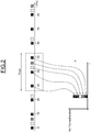
- Step 1 To determine the transient load peak phase indicator, a first step 1 of detecting an isolated load peak is carried out. Step 1 is also illustrated by the figure 2 on which we can see the transmission of frames over time in the upper part of the figure and the integrated value compared to a detection threshold in the lower part of the figure.
- the number of frames (denoted NbTramesFenetre) sent in an integration window having a first duration TMax is counted.
- the value of the number of frames counted is equal to the number of frames that can flow in the BUS, NbMaxTrames.
- NbMoyTrames is the sum of the inverse of the periods of each frame multiplied by the duration of the observation window
- a threshold P is then defined, homogeneous with a number of frames, the value of which is between the average value (NbMoyTrames) and the maximum value (NbMaxTrames).
- a second step 2 is carried out comprising the following sub-steps.
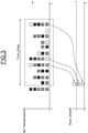
- the second step is illustrated by the figure 3 on which we can see the load peaks detected over time in the upper part of the figure and the integrated value compared to a detection threshold in the lower part of the figure.
- Tmax_phase time integration window
- a threshold T is fixed, the value of which depends on the design of the CAN BUS.
- Defense mechanisms can then be applied to get out of this phase as quickly as possible.
- data network protection mechanisms are triggered during a step 4.
- a self-leveling of the load peaks is applied in particular.
- a single negative time offset is determined during step 5.
- this negative time offset is applied when sending all the computer frames, for the duration of the load peak.
- the negative time offset is added to any preexisting time offset.
- the value of the negative time offset of each computer is determined by random drawing, the value being between 0 and the value of the smallest frame transmission period of the computer.
- the steps for determining the occurrences of load peaks, determining the phases of load peaks and applying a random negative time offset are repeated in a loop with a configurable periodicity.
Landscapes
- Engineering & Computer Science (AREA)
- Computer Networks & Wireless Communication (AREA)
- Signal Processing (AREA)
- Quality & Reliability (AREA)
- Environmental & Geological Engineering (AREA)
- Data Exchanges In Wide-Area Networks (AREA)
- Small-Scale Networks (AREA)
Description
L'invention a pour domaine technique les réseaux de données d'un véhicule automobile, et plus particulièrement de tels réseaux à la norme CAN.The technical field of the invention is the data networks of a motor vehicle, and more particularly such networks according to the CAN standard.
Actuellement, la charge réseau moyenne d'un BUS est estimée en réalisant le rapport entre le temps d'activité effective du BUS sur une période d'observation. Ainsi, une charge de 50% du BUS implique que l'activité sur le BUS représente la moitié du temps d'observation, si on prend une fenêtre d'observation suffisamment grande.Currently, the average network load of a BUS is estimated by realizing the ratio between the effective activity time of the BUS over an observation period. Thus, a load of 50% of the BUS implies that the activity on the BUS represents half of the observation time, if we take a sufficiently large observation window.
Par BUS, on entend un réseau de données et/ou informatique, de type liaison partagée, pouvant être partagé entre différents dispositifs, et permettant d'échanger des données. Un BUS est notamment un réseau de données de type temps réel.By BUS is meant a data and / or computer network, of the shared link type, which can be shared between different devices, and which makes it possible to exchange data. A BUS is in particular a real-time type data network.
Par réseau CAN, on entend un contrôleur de réseau de zone (« Controller Area Network » en langue anglaise, acronyme « CAN ») qui permet le raccordement à un même câble, ou BUS, d'un grand nombre de calculateurs qui communiquent à tour de rôle, ou simultanément. La communication des calculateurs est assurée par l'émission de trames correspondant à un ensemble de données codifiées selon des normes prédéfinies. Chaque trame est émise périodiquement, avec une période d'émission qui lui est propre et qui est déterminée lors de la conception du calculateur et/ou du BUS. Chaque calculateur peut émettre une ou plusieurs trames.The term CAN network is understood to mean an area network controller (“Controller Area Network” in English, acronym “CAN”) which allows the connection to the same cable, or BUS, of a large number of computers which communicate in turn role, or simultaneously. The computers are communicated by the transmission of frames corresponding to a set of data coded according to predefined standards. Each frame is transmitted periodically, with its own transmission period which is determined during the design of the computer and / or the BUS. Each computer can transmit one or more frames.
Etant donné que les horloges des différents calculateurs connectés à un BUS CAN ne sont pas synchronisées, on pourrait espérer que l'émission des trames des différents calculateurs soit distribuée uniformément dans le temps. Ainsi, les temps d'accès au BUS devraient être éloignés des temps d'accès, dans une situation dite du pire cas.Given that the clocks of the various computers connected to a CAN BUS are not synchronized, it might be hoped that the transmission of the frames of the various computers is distributed uniformly over time. Thus, the access times to the BUS should be distant from the access times, in a situation called the worst case.
Cependant, l'observation d'enregistrement de l'activité de BUS lors d'essais sur route enseigne que la charge réseau d'un BUS CAN n'est pas distribuée de façon homogène dans le temps. Suite à la dérive naturelle des horloges des calculateurs, on observe des phases transitoires assez longues (plusieurs minutes) pendant lesquelles les horloges de plusieurs calculateurs peuvent se synchroniser et produire des phénomènes de pics de charge. Ces pics de charge sont particulièrement préjudiciables pour ce type de réseaux qui ont pour but de fonctionner en temps réel, c'est-à-dire sans délai notable entre l'émission et la réception d'informations.However, the observation of recording of BUS activity during road tests teaches that the network load of a CAN BUS is not distributed evenly over time. Following the natural drift of the clocks of the computers, we observe fairly long transient phases (several minutes) during which the clocks of several computers can synchronize and produce peak load phenomena. These load peaks are particularly detrimental for this type of network which aims to operate in real time, that is to say without significant delay between the transmission and reception of information.
Lorsque le comportement temps-réel du BUS CAN est affecté par des pics de charge, les temps d'accès au BUS s'approchent des conditions « au pire cas ». En effet, tant que le niveau de charge de BUS CAN reste à des niveaux raisonnables (<50%), on peut considérer que la somme des temps additionnels d'arbitrage induits par les pics de charge ne dépassera les délais admissibles pour la communication en temps réel entre les calculateurs connectés au BUS.When the real-time behavior of the CAN BUS is affected by load peaks, the access times to the BUS approach “worst case” conditions. Indeed, as long as the CAN BUS load level remains at reasonable levels (<50%), we can consider that the sum of the additional arbitration times induced by the load peaks will not exceed the admissible delays for communication in real time between the computers connected to the BUS.
Si l'on augmente la charge de BUS CAN bien au-delà des limites raisonnables (>>50%), les pics de charge vont se généraliser. Dans un tel cas, les temps d'accès au BUS vont s'approcher de la situation « au pire cas ». Si cela arrive, on risque de ne plus respecter les exigences relatives aux délais admissibles pour la communication en temps réel entre les calculateurs connectés au BUS.If the CAN BUS load is increased far beyond reasonable limits (>> 50%), the load peaks will generalize. In such a case, the bus access times will approach the "worst case" situation. If this happens, there is a risk of no longer complying with the requirements relating to the admissible delays for real-time communication between the computers connected to the BUS.
De l'état de la technique, on connaît le document
Le document
Dans le document
Le document
Il apparaît qu'il demeure un problème relatif à la mise à disposition des informations de qualité de service du BUS, et à la correction des pics de charge lorsque la qualité de service du BUS est insatisfaisante.It appears that there remains a problem relating to the provision of quality of service information from the BUS, and to the correction of load peaks when the quality of service of the BUS is unsatisfactory.
Un but de l'invention est de réduire les phases transitoires de pics de charge au minimum pour améliorer le temps réel du réseau de données.An object of the invention is to reduce the transient phases of load peaks to the minimum in order to improve the real time of the data network.
Un objet de l'invention est un procédé de lissage des pics de charge d'un réseau de données en temps réel, comprenant les étapes suivantes :
- on détecte les pics de charge apparaissant dans le réseau de données,
- on compte le nombre de pics de charge sur une fenêtre d'intégration présentant une première durée, la fenêtre d'intégration se déplaçant avec le temps,
- on détermine que le réseau de données est en situation de phase transitoire de pics de charge si le nombre de pics de charge détectés est supérieur à un premier seuil, puis
- on déclenche des mécanismes de protection du réseau de données.
- load peaks appearing in the data network are detected,
- the number of load peaks is counted on an integration window having a first duration, the integration window moving over time,
- it is determined that the data network is in a transient phase of load peaks if the number of detected load peaks is greater than a first threshold, then
- data network protection mechanisms are triggered.
On peut réaliser une détection de pic isolé de charge en mettant en œuvre les étapes suivantes :
- on compte le nombre de trames émises dans une fenêtre d'intégration en temps de deuxième durée,
- on détermine la valeur moyenne des trames en multipliant le nombre de trames émises par le taux de charge du réseau de données,
- on définit un premier seuil entre le nombre moyen de trames et le nombre maximal de trames du réseau de données, et
- on détermine qu'un pic de charge a lieu si le nombre de trames est supérieur au premier seuil.
- the number of frames sent in an integration window in second time is counted,
- the average value of the frames is determined by multiplying the number of frames sent by the load rate of the data network,
- a first threshold is defined between the average number of frames and the maximum number of frames of the data network, and
- it is determined that a load peak occurs if the number of frames is greater than the first threshold.
La première durée peut être supérieure à la deuxième durée.The first duration may be greater than the second duration.
Les mécanismes de protection du réseau de données peuvent comprendre un autolissage des pics de charge au cours duquel on applique un décalage temporel distinct pour chacun des calculateurs connectés au réseau de données impliqués dans la phase transitoire de pics de charge.The protection mechanisms of the data network can include a self-leveling of the load peaks during which a distinct time offset is applied for each of the computers connected to the data network involved in the transient phase of load peaks.
On peut effectuer un autolissage des pics de charge d'un réseau de données en temps réel comprenant au moins deux calculateurs en mettant en œuvre les étapes suivantes :
- pour chacun des calculateurs participant à une phase transitoire de pics de charge, on détermine un décalage temporel négatif,
- on applique ce décalage temporel négatif lors de l'envoi de toutes les trames du calculateur, le décalage temporel négatif étant ajouté à un éventuel décalage temporel préexistant.
- for each of the computers participating in a transient phase of load peaks, a negative time offset is determined,
- this negative time offset is applied when all the computer frames are sent, the negative time offset being added to a possible preexisting time offset.
On peut déterminer la valeur du décalage temporel négatif de chaque calculateur par tirage au sort aléatoire, la valeur étant comprise entre zéro et la valeur de la plus petite période d'émission de trame du calculateur.The value of the negative time offset of each computer can be determined by random draw, the value being between zero and the value of the smallest frame transmission period of the computer.
Un autre objet de l'invention est un système de lissage des pics de charge d'un réseau de données en temps réel. Le système comprend des moyens pour détecter les pics de charge apparaissant dans le réseau de données,
des moyens de comptage du nombre de pics de charge détectés sur une fenêtre d'intégration présentant une première durée, la fenêtre d'intégration se déplaçant avec le temps,
des moyens de détermination d'une situation de phase transitoire de pics de charge si le nombre de pics de charge détectés est supérieur à un premier seuil, et,
des moyens de protection du réseau de données.Another object of the invention is a system for smoothing the load peaks of a data network in real time. The system comprises means for detecting the peaks of load appearing in the data network,
means for counting the number of charge peaks detected on an integration window having a first duration, the integration window moving over time,
means for determining a transient phase situation of load peaks if the number of detected load peaks is greater than a first threshold, and,
means of protecting the data network.
Les moyens de protection du réseau de données peuvent comprendre des moyens d'autolissage des pics de charge par application d'un décalage temporel distinct pour chacun des calculateurs connectés au réseau de données impliqués dans la phase transitoire de pics de charge.The data network protection means can comprise means for self-leveling the load peaks by applying a separate time offset for each of the computers connected to the data network involved in the transient phase of load peaks.
D'autres buts, caractéristiques et avantages apparaîtront à la lecture de la description suivante donnée uniquement en tant qu'exemple non limitatif et faite en référence aux dessins annexés sur lesquels :
- la
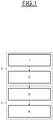
figure 1 illustre les principales étapes d'un procédé de lissage des pics de charge d'un réseau de données en temps réel, - la
figure 2 illustre la détection de pics de charge, et - la
figure 3 illustre la détection de phases de pics de charge.
- the
figure 1 illustrates the main steps of a process for smoothing the load peaks of a real-time data network, - the
figure 2 illustrates the detection of load peaks, and - the
figure 3 illustrates the detection of load peak phases.
La dérive des horloges de différents calculateurs peut provoquer un pic de charge sur le BUS CAN au cours duquel tous les calculateurs essayent d'émettre des trames en même temps. Le pire cas arrive quand toutes les trames existantes dans le BUS sont envoyées collées les unes après les autres.The drift of the clocks of different computers can cause a load peak on the CAN BUS during which all the computers try to send frames at the same time. The worst case occurs when all the frames existing in the BUS are sent pasted one after the other.
Afin de caractériser les phases de pics de charge, deux valeurs vont être calculées, une valeur de nombre de trames, et une valeur de nombre de pics de chargeIn order to characterize the phases of load peaks, two values will be calculated, a value of number of frames, and a value of number of load peaks
Le nombre de trames pouvant circuler dans le BUS, noté NbMaxTrames et la somme des durées de transmission de toutes les trames pouvant circuler dans le BUS noté TMax. On remarque que Tmax est également équivalent au temps de transmission de la trame la moins prioritaire dans le BUS, dans une situation de pire cas.The number of frames which can circulate in the BUS, denoted NbMaxTrames and the sum of the transmission times of all the frames which can circulate in the BUS denoted TMax. Note that Tmax is also equivalent to the transmission time of the lowest priority frame in the BUS, in a worst case situation.
Pour déterminer l'indicateur de phase transitoire de pics de charge, on réalise une première étape 1 de détection de pic isolé de charge. L'étape 1 est également illustrée par la
Au cours de cette première étape, on compte le nombre de trames (noté NbTramesFenetre) émises dans une fenêtre d'intégration présentant une première durée TMax. Dans le pire des cas, la valeur du nombre de trames comptées est égal au nombre de trames pouvant circuler dans le BUS, NbMaxTrames.During this first step, the number of frames (denoted NbTramesFenetre) sent in an integration window having a first duration TMax is counted. In the worst case, the value of the number of frames counted is equal to the number of frames that can flow in the BUS, NbMaxTrames.
La valeur moyenne NbMoyTrames des trames dans la fenêtre Tmax peut être estimée par la formule suivante : ![]()
- i variant de 1 à NbTrames
- Pi= Période de la trame i
- ∑(1/Pi)=Trames/s
- Tmax= durée de la fenêtre en secondes
- NbTrames=Nombre de trames différentes pouvant être émises
- i varying from 1 to NbTrames
- Pi = Period of frame i
- ∑ (1 / Pi) = Frames / s
- Tmax = window duration in seconds
- NbTrames = Number of different frames that can be sent
En d'autres termes, NbMoyTrames est la somme de l'inverse des périodes de chaque trame multipliée par la durée de la fenêtre d'observationIn other words, NbMoyTrames is the sum of the inverse of the periods of each frame multiplied by the duration of the observation window
On définit ensuite un seuil P, homogène à un nombre de trames, dont la valeur est comprise entre la valeur moyenne (NbMoyTrames) et la valeur maximale (NbMaxTrames).A threshold P is then defined, homogeneous with a number of frames, the value of which is between the average value (NbMoyTrames) and the maximum value (NbMaxTrames).
On détermine ensuite si le nombre de trames NbTramesFenetre est supérieur au seuil P. Si tel est le cas, on considère qu'un pic de charge a lieu dans le BUS. En fonction du paramétrage du seuil P, la détection des pics isolés de charge sera plus ou moins sensible.It is then determined whether the number of NbTramesFenetre frames is greater than the threshold P. If this is the case, it is considered that a load peak takes place in the BUS. Depending on the setting of threshold P, the detection of isolated load peaks will be more or less sensitive.
On cherche ensuite à distinguer un pic de charge isolé d'une phase transitoire de pics de charge répétitifs. Pour cela, on réalise une deuxième étape 2 comprenant les sous-étapes suivantes. La deuxième étape est illustrée par la
On compte le nombre (Nbpic_phase) de pics de charge sur une fenêtre d'intégration en temps (Tmax_phase). La taille de cette fenêtre d'intégration en temps présentant une deuxième durée (Tmax_phase) est paramétrable, et généralement plus grande que la fenêtre d'intégration en temps de première durée (Tmax) permettant de compter le nombre de trames (Nbtrames), et permet de déterminer la réactivité de détection des phases transitoires de pics de charge.We count the number (Nbpic_phase) of load peaks on a time integration window (Tmax_phase). The size of this integration window in time having a second duration (Tmax_phase) is configurable, and generally larger than the integration window in time of first duration (Tmax) allowing the number of frames (Nbtrames) to be counted, and allows to determine the reactivity of detection of transient phases of load peaks.
On fixe un seuil T, dont la valeur dépend de la conception du BUS CAN.A threshold T is fixed, the value of which depends on the design of the CAN BUS.
On détermine ensuite si le nombre de pics de charge détectés (Nbpic_phase) dépasse le seuil T. Dans un tel cas, on déduira qu'on est rentré en situation de phase transitoire de pics de charge. Les étapes 1 et 2 permettent ainsi de réaliser une détermination 3 de phase transitoire de Pics de Charge.It is then determined whether the number of load peaks detected (Nbpic_phase) exceeds the threshold T. In such a case, it will be deduced that we have returned to a transient load peak phase. The
Des mécanismes de défense peuvent alors être appliqués pour sortir au plus vite de cette phase. Pour cela, on déclenche des mécanismes de protection du réseau de données au cours d'une étape 4. Parmi ces mécanismes, on applique notamment un autolissage des pics de chargeDefense mechanisms can then be applied to get out of this phase as quickly as possible. To do this, data network protection mechanisms are triggered during a
Pour cela, on applique les étapes 5 et 6 suivantes:
Pour chacun des calculateurs participant à une phase transitoire de pics de charge, on détermine un décalage temporel négatif unique au cours de l'étape 5. Au cours d'une étape 6, on applique ce décalage temporel négatif lors de l'envoi de toutes les trames du calculateur, pour la durée du pic de charge. Le décalage temporel négatif est ajouté à un éventuel décalage temporel préexistant.For this, the following
For each of the computers participating in a transient phase of load peaks, a single negative time offset is determined during
On détermine la valeur du décalage temporel négatif de chaque calculateur par tirage au sort aléatoire, la valeur étant comprise entre 0 et la valeur de la plus petite période d'émission de trame du calculateur.The value of the negative time offset of each computer is determined by random drawing, the value being between 0 and the value of the smallest frame transmission period of the computer.
Les étapes de détermination des occurrences de pics de charge, de détermination de phases de pics de charge et d'application d'un décalage temporel négatif aléatoire sont répétées en boucle avec une périodicité paramétrable.The steps for determining the occurrences of load peaks, determining the phases of load peaks and applying a random negative time offset are repeated in a loop with a configurable periodicity.
Claims (6)
- Method for smoothing the load peaks of a real-time data network, comprising the following steps:the load peaks that appear in the data network are detected,the number of load peaks over an integration window that has a first duration is counted, the integration window moving over time,the data network is determined as being in a load peak transient phase situation if the number of detected load peaks is higher than a first threshold, thencharacterized in that it comprises the following steps:
mechanisms for protecting the data network are triggered, said mechanisms comprising self-smoothing of the load peaks, during which process a separate time offset is applied to each of the computers connected to the data network that are involved in the load peak transient phase. - Method according to Claim 1, wherein isolated load peak detection is performed by carrying out the following steps:the number of frames transmitted in a time-integration window of a second duration is counted, the average value of the frames is determined by multiplying the number of frames transmitted by the load rate of the data network,a second threshold is defined, the value of said second threshold being between the average number of frames and the maximum number of frames of the data network, anda load peak is determined as occurring if the number of frames is higher than the second threshold.
- Method according to either one of the preceding claims, wherein the first duration is longer than the second duration.
- Method according to one of Claims 1 to 3, wherein self-smoothing of the load peaks of the real-time data network comprising at least two computers is performed by carrying out the following steps:for each of the computers that is involved in a load peak transient phase, a negative time offset is determined,this negative time offset is applied when all the frames of the computer are sent, the negative time offset being added to any pre-existing time offset.
- Method according to Claim 4, wherein the value of the negative time offset of each computer is determined by random draw, the value being between zero and the value of the shortest frame transmission period of the computer.
- System for smoothing the load peaks of a real-time data network, comprising:means for detecting the load peaks that appear in the data network,means for counting the number of load peaks detected over an integration window that has a first duration, the integration window moving over time, means for determining a load peak transient phase situation if the number of detected load peaks is higher than a first threshold, andcharacterized in that it comprises:
means for protecting the data network comprising means for self-smoothing of the load peaks by applying a separate time offset to each of the computers connected to the data network that are involved in the load peak transient phase.
Applications Claiming Priority (2)
| Application Number | Priority Date | Filing Date | Title |
|---|---|---|---|
| FR1353272A FR3004613B1 (en) | 2013-04-11 | 2013-04-11 | METHOD AND SYSTEM FOR SMOOTHING LOAD PICS OF A REAL TIME DATA NETWORK. |
| PCT/FR2014/050801 WO2014167216A1 (en) | 2013-04-11 | 2014-04-03 | Method and system for smoothing load peaks of a data network in real time |
Publications (2)
| Publication Number | Publication Date |
|---|---|
| EP2984792A1 EP2984792A1 (en) | 2016-02-17 |
| EP2984792B1 true EP2984792B1 (en) | 2020-06-24 |
Family
ID=48795708
Family Applications (1)
| Application Number | Title | Priority Date | Filing Date |
|---|---|---|---|
| EP14720652.8A Not-in-force EP2984792B1 (en) | 2013-04-11 | 2014-04-03 | Method and system for smoothing load peaks of a data network in real time |
Country Status (3)
| Country | Link |
|---|---|
| EP (1) | EP2984792B1 (en) |
| FR (1) | FR3004613B1 (en) |
| WO (1) | WO2014167216A1 (en) |
Citations (1)
| Publication number | Priority date | Publication date | Assignee | Title |
|---|---|---|---|---|
| EP1152633A1 (en) * | 2000-05-01 | 2001-11-07 | Lucent Technologies Inc. | Fuzzy-logic based overload detection and correction for packet gateways |
Family Cites Families (3)
| Publication number | Priority date | Publication date | Assignee | Title |
|---|---|---|---|---|
| DE102006039123A1 (en) | 2006-08-21 | 2008-03-06 | Robert Bosch Gmbh | Method and device for feeding data into a serial data bus |
| US7894337B2 (en) * | 2007-06-29 | 2011-02-22 | Alcatel-Lucent Usa Inc. | Method and system for unified overload and overflow control to support VoIP and multiple QOS flow traffic in communication network |
| KR20090010454A (en) | 2007-07-23 | 2009-01-30 | 주식회사 만도 | CANBUS LOAD STABILIZATION |
-
2013
- 2013-04-11 FR FR1353272A patent/FR3004613B1/en not_active Expired - Fee Related
-
2014
- 2014-04-03 EP EP14720652.8A patent/EP2984792B1/en not_active Not-in-force
- 2014-04-03 WO PCT/FR2014/050801 patent/WO2014167216A1/en not_active Ceased
Patent Citations (1)
| Publication number | Priority date | Publication date | Assignee | Title |
|---|---|---|---|---|
| EP1152633A1 (en) * | 2000-05-01 | 2001-11-07 | Lucent Technologies Inc. | Fuzzy-logic based overload detection and correction for packet gateways |
Also Published As
| Publication number | Publication date |
|---|---|
| FR3004613B1 (en) | 2016-07-29 |
| WO2014167216A1 (en) | 2014-10-16 |
| EP2984792A1 (en) | 2016-02-17 |
| FR3004613A1 (en) | 2014-10-17 |
Similar Documents
| Publication | Publication Date | Title |
|---|---|---|
| EP4205362B1 (en) | Prioritized data flow network embedded in a vehicle | |
| US8756031B2 (en) | Matched filter testing of data transmission cables | |
| WO2018078182A1 (en) | Parking space management method | |
| EP2984792B1 (en) | Method and system for smoothing load peaks of a data network in real time | |
| CN106603256A (en) | Flow control method and apparatus | |
| US9674726B1 (en) | Methods and systems for improved bandwidth estimation | |
| FR2898445A1 (en) | METHOD AND DEVICE FOR DETECTING INTRUSION TENTATIVES ON A COMMUNICATION LINK BETWEEN AN AIRCRAFT AND A SOIL STATION. | |
| CN111083174B (en) | Firewall dual-computer hot standby system, standby firewall and state processing method and device | |
| FR3076161B1 (en) | (EN) SLAVE ORGAN FAULT SUPERVISION DEVICE (S) FOR A MASTER ORGAN OF A MULTIPLEX NETWORK. | |
| US8068410B2 (en) | Bias correction for scrubbing providers | |
| CN106161123A (en) | Detection method that electronic channel is congested and detection device | |
| US10241882B2 (en) | System and method for dynamic adjustment of logging | |
| WO2003061198A1 (en) | Transport network management system based on trend analysis | |
| CN109710552A (en) | Bus transfer method for evaluating quality, system and computer storage medium | |
| EP3317771B1 (en) | Master facility with means for analysing a defect in the physical layer of a bidirectional video network | |
| CN112350880B (en) | Overload detection method, system, computer readable storage medium and electronic device | |
| CN106254159A (en) | Link method for detecting abnormality and device | |
| EP3084666A1 (en) | Device for interconnecting communication networks with controlled security | |
| EP3796195A1 (en) | Abnormality detection device and abnormality detection method | |
| Sarlas et al. | Public transport reliability: the spatio-temporal accessibility case | |
| FR2976434A1 (en) | Device for detecting congestion in e.g. communication network for e.g. communication unit, has analysis unit determining whether time difference data satisfies rule for determining whether communication network is subject to congestion | |
| EP2633651A1 (en) | Method and device for detecting the congestion of a transmission link | |
| EP1328084A1 (en) | Determination of the cause of degradation of the quality of a service based on the evolution of a set of services | |
| JP2019208139A5 (en) | ||
| EP2286526B1 (en) | Method and device for preventing failure |
Legal Events
| Date | Code | Title | Description |
|---|---|---|---|
| PUAI | Public reference made under article 153(3) epc to a published international application that has entered the european phase |
Free format text: ORIGINAL CODE: 0009012 |
|
| 17P | Request for examination filed |
Effective date: 20150827 |
|
| AK | Designated contracting states |
Kind code of ref document: A1 Designated state(s): AL AT BE BG CH CY CZ DE DK EE ES FI FR GB GR HR HU IE IS IT LI LT LU LV MC MK MT NL NO PL PT RO RS SE SI SK SM TR |
|
| AX | Request for extension of the european patent |
Extension state: BA ME |
|
| DAX | Request for extension of the european patent (deleted) | ||
| STAA | Information on the status of an ep patent application or granted ep patent |
Free format text: STATUS: EXAMINATION IS IN PROGRESS |
|
| 17Q | First examination report despatched |
Effective date: 20181022 |
|
| GRAP | Despatch of communication of intention to grant a patent |
Free format text: ORIGINAL CODE: EPIDOSNIGR1 |
|
| STAA | Information on the status of an ep patent application or granted ep patent |
Free format text: STATUS: GRANT OF PATENT IS INTENDED |
|
| INTG | Intention to grant announced |
Effective date: 20200224 |
|
| GRAS | Grant fee paid |
Free format text: ORIGINAL CODE: EPIDOSNIGR3 |
|
| GRAA | (expected) grant |
Free format text: ORIGINAL CODE: 0009210 |
|
| STAA | Information on the status of an ep patent application or granted ep patent |
Free format text: STATUS: THE PATENT HAS BEEN GRANTED |
|
| AK | Designated contracting states |
Kind code of ref document: B1 Designated state(s): AL AT BE BG CH CY CZ DE DK EE ES FI FR GB GR HR HU IE IS IT LI LT LU LV MC MK MT NL NO PL PT RO RS SE SI SK SM TR |
|
| REG | Reference to a national code |
Ref country code: GB Ref legal event code: FG4D Free format text: NOT ENGLISH |
|
| REG | Reference to a national code |
Ref country code: CH Ref legal event code: EP |
|
| REG | Reference to a national code |
Ref country code: DE Ref legal event code: R096 Ref document number: 602014066969 Country of ref document: DE |
|
| REG | Reference to a national code |
Ref country code: AT Ref legal event code: REF Ref document number: 1285002 Country of ref document: AT Kind code of ref document: T Effective date: 20200715 |
|
| REG | Reference to a national code |
Ref country code: IE Ref legal event code: FG4D Free format text: LANGUAGE OF EP DOCUMENT: FRENCH |
|
| PG25 | Lapsed in a contracting state [announced via postgrant information from national office to epo] |
Ref country code: GR Free format text: LAPSE BECAUSE OF FAILURE TO SUBMIT A TRANSLATION OF THE DESCRIPTION OR TO PAY THE FEE WITHIN THE PRESCRIBED TIME-LIMIT Effective date: 20200925 Ref country code: NO Free format text: LAPSE BECAUSE OF FAILURE TO SUBMIT A TRANSLATION OF THE DESCRIPTION OR TO PAY THE FEE WITHIN THE PRESCRIBED TIME-LIMIT Effective date: 20200924 Ref country code: FI Free format text: LAPSE BECAUSE OF FAILURE TO SUBMIT A TRANSLATION OF THE DESCRIPTION OR TO PAY THE FEE WITHIN THE PRESCRIBED TIME-LIMIT Effective date: 20200624 Ref country code: SE Free format text: LAPSE BECAUSE OF FAILURE TO SUBMIT A TRANSLATION OF THE DESCRIPTION OR TO PAY THE FEE WITHIN THE PRESCRIBED TIME-LIMIT Effective date: 20200624 Ref country code: LT Free format text: LAPSE BECAUSE OF FAILURE TO SUBMIT A TRANSLATION OF THE DESCRIPTION OR TO PAY THE FEE WITHIN THE PRESCRIBED TIME-LIMIT Effective date: 20200624 |
|
| REG | Reference to a national code |
Ref country code: LT Ref legal event code: MG4D |
|
| PG25 | Lapsed in a contracting state [announced via postgrant information from national office to epo] |
Ref country code: BG Free format text: LAPSE BECAUSE OF FAILURE TO SUBMIT A TRANSLATION OF THE DESCRIPTION OR TO PAY THE FEE WITHIN THE PRESCRIBED TIME-LIMIT Effective date: 20200924 Ref country code: RS Free format text: LAPSE BECAUSE OF FAILURE TO SUBMIT A TRANSLATION OF THE DESCRIPTION OR TO PAY THE FEE WITHIN THE PRESCRIBED TIME-LIMIT Effective date: 20200624 Ref country code: LV Free format text: LAPSE BECAUSE OF FAILURE TO SUBMIT A TRANSLATION OF THE DESCRIPTION OR TO PAY THE FEE WITHIN THE PRESCRIBED TIME-LIMIT Effective date: 20200624 Ref country code: HR Free format text: LAPSE BECAUSE OF FAILURE TO SUBMIT A TRANSLATION OF THE DESCRIPTION OR TO PAY THE FEE WITHIN THE PRESCRIBED TIME-LIMIT Effective date: 20200624 |
|
| REG | Reference to a national code |
Ref country code: NL Ref legal event code: MP Effective date: 20200624 |
|
| REG | Reference to a national code |
Ref country code: AT Ref legal event code: MK05 Ref document number: 1285002 Country of ref document: AT Kind code of ref document: T Effective date: 20200624 |
|
| PG25 | Lapsed in a contracting state [announced via postgrant information from national office to epo] |
Ref country code: AL Free format text: LAPSE BECAUSE OF FAILURE TO SUBMIT A TRANSLATION OF THE DESCRIPTION OR TO PAY THE FEE WITHIN THE PRESCRIBED TIME-LIMIT Effective date: 20200624 Ref country code: NL Free format text: LAPSE BECAUSE OF FAILURE TO SUBMIT A TRANSLATION OF THE DESCRIPTION OR TO PAY THE FEE WITHIN THE PRESCRIBED TIME-LIMIT Effective date: 20200624 |
|
| PG25 | Lapsed in a contracting state [announced via postgrant information from national office to epo] |
Ref country code: AT Free format text: LAPSE BECAUSE OF FAILURE TO SUBMIT A TRANSLATION OF THE DESCRIPTION OR TO PAY THE FEE WITHIN THE PRESCRIBED TIME-LIMIT Effective date: 20200624 Ref country code: EE Free format text: LAPSE BECAUSE OF FAILURE TO SUBMIT A TRANSLATION OF THE DESCRIPTION OR TO PAY THE FEE WITHIN THE PRESCRIBED TIME-LIMIT Effective date: 20200624 Ref country code: SM Free format text: LAPSE BECAUSE OF FAILURE TO SUBMIT A TRANSLATION OF THE DESCRIPTION OR TO PAY THE FEE WITHIN THE PRESCRIBED TIME-LIMIT Effective date: 20200624 Ref country code: IT Free format text: LAPSE BECAUSE OF FAILURE TO SUBMIT A TRANSLATION OF THE DESCRIPTION OR TO PAY THE FEE WITHIN THE PRESCRIBED TIME-LIMIT Effective date: 20200624 Ref country code: CZ Free format text: LAPSE BECAUSE OF FAILURE TO SUBMIT A TRANSLATION OF THE DESCRIPTION OR TO PAY THE FEE WITHIN THE PRESCRIBED TIME-LIMIT Effective date: 20200624 Ref country code: RO Free format text: LAPSE BECAUSE OF FAILURE TO SUBMIT A TRANSLATION OF THE DESCRIPTION OR TO PAY THE FEE WITHIN THE PRESCRIBED TIME-LIMIT Effective date: 20200624 Ref country code: ES Free format text: LAPSE BECAUSE OF FAILURE TO SUBMIT A TRANSLATION OF THE DESCRIPTION OR TO PAY THE FEE WITHIN THE PRESCRIBED TIME-LIMIT Effective date: 20200624 Ref country code: PT Free format text: LAPSE BECAUSE OF FAILURE TO SUBMIT A TRANSLATION OF THE DESCRIPTION OR TO PAY THE FEE WITHIN THE PRESCRIBED TIME-LIMIT Effective date: 20201026 |
|
| PG25 | Lapsed in a contracting state [announced via postgrant information from national office to epo] |
Ref country code: PL Free format text: LAPSE BECAUSE OF FAILURE TO SUBMIT A TRANSLATION OF THE DESCRIPTION OR TO PAY THE FEE WITHIN THE PRESCRIBED TIME-LIMIT Effective date: 20200624 Ref country code: SK Free format text: LAPSE BECAUSE OF FAILURE TO SUBMIT A TRANSLATION OF THE DESCRIPTION OR TO PAY THE FEE WITHIN THE PRESCRIBED TIME-LIMIT Effective date: 20200624 Ref country code: IS Free format text: LAPSE BECAUSE OF FAILURE TO SUBMIT A TRANSLATION OF THE DESCRIPTION OR TO PAY THE FEE WITHIN THE PRESCRIBED TIME-LIMIT Effective date: 20201024 |
|
| REG | Reference to a national code |
Ref country code: DE Ref legal event code: R097 Ref document number: 602014066969 Country of ref document: DE |
|
| PG25 | Lapsed in a contracting state [announced via postgrant information from national office to epo] |
Ref country code: DK Free format text: LAPSE BECAUSE OF FAILURE TO SUBMIT A TRANSLATION OF THE DESCRIPTION OR TO PAY THE FEE WITHIN THE PRESCRIBED TIME-LIMIT Effective date: 20200624 |
|
| PLBE | No opposition filed within time limit |
Free format text: ORIGINAL CODE: 0009261 |
|
| STAA | Information on the status of an ep patent application or granted ep patent |
Free format text: STATUS: NO OPPOSITION FILED WITHIN TIME LIMIT |
|
| 26N | No opposition filed |
Effective date: 20210325 |
|
| PG25 | Lapsed in a contracting state [announced via postgrant information from national office to epo] |
Ref country code: SI Free format text: LAPSE BECAUSE OF FAILURE TO SUBMIT A TRANSLATION OF THE DESCRIPTION OR TO PAY THE FEE WITHIN THE PRESCRIBED TIME-LIMIT Effective date: 20200624 |
|
| PG25 | Lapsed in a contracting state [announced via postgrant information from national office to epo] |
Ref country code: MC Free format text: LAPSE BECAUSE OF FAILURE TO SUBMIT A TRANSLATION OF THE DESCRIPTION OR TO PAY THE FEE WITHIN THE PRESCRIBED TIME-LIMIT Effective date: 20200624 |
|
| PG25 | Lapsed in a contracting state [announced via postgrant information from national office to epo] |
Ref country code: LU Free format text: LAPSE BECAUSE OF NON-PAYMENT OF DUE FEES Effective date: 20210403 |
|
| REG | Reference to a national code |
Ref country code: BE Ref legal event code: MM Effective date: 20210430 |
|
| PG25 | Lapsed in a contracting state [announced via postgrant information from national office to epo] |
Ref country code: LI Free format text: LAPSE BECAUSE OF NON-PAYMENT OF DUE FEES Effective date: 20210430 Ref country code: CH Free format text: LAPSE BECAUSE OF NON-PAYMENT OF DUE FEES Effective date: 20210430 |
|
| PG25 | Lapsed in a contracting state [announced via postgrant information from national office to epo] |
Ref country code: IE Free format text: LAPSE BECAUSE OF NON-PAYMENT OF DUE FEES Effective date: 20210403 |
|
| PG25 | Lapsed in a contracting state [announced via postgrant information from national office to epo] |
Ref country code: IS Free format text: LAPSE BECAUSE OF FAILURE TO SUBMIT A TRANSLATION OF THE DESCRIPTION OR TO PAY THE FEE WITHIN THE PRESCRIBED TIME-LIMIT Effective date: 20201024 |
|
| PG25 | Lapsed in a contracting state [announced via postgrant information from national office to epo] |
Ref country code: BE Free format text: LAPSE BECAUSE OF NON-PAYMENT OF DUE FEES Effective date: 20210430 |
|
| PG25 | Lapsed in a contracting state [announced via postgrant information from national office to epo] |
Ref country code: HU Free format text: LAPSE BECAUSE OF FAILURE TO SUBMIT A TRANSLATION OF THE DESCRIPTION OR TO PAY THE FEE WITHIN THE PRESCRIBED TIME-LIMIT; INVALID AB INITIO Effective date: 20140403 |
|
| PG25 | Lapsed in a contracting state [announced via postgrant information from national office to epo] |
Ref country code: CY Free format text: LAPSE BECAUSE OF FAILURE TO SUBMIT A TRANSLATION OF THE DESCRIPTION OR TO PAY THE FEE WITHIN THE PRESCRIBED TIME-LIMIT Effective date: 20200624 |
|
| P01 | Opt-out of the competence of the unified patent court (upc) registered |
Effective date: 20230608 |
|
| PGFP | Annual fee paid to national office [announced via postgrant information from national office to epo] |
Ref country code: FR Payment date: 20230424 Year of fee payment: 10 Ref country code: DE Payment date: 20230420 Year of fee payment: 10 |
|
| PGFP | Annual fee paid to national office [announced via postgrant information from national office to epo] |
Ref country code: GB Payment date: 20230419 Year of fee payment: 10 |
|
| PG25 | Lapsed in a contracting state [announced via postgrant information from national office to epo] |
Ref country code: MK Free format text: LAPSE BECAUSE OF FAILURE TO SUBMIT A TRANSLATION OF THE DESCRIPTION OR TO PAY THE FEE WITHIN THE PRESCRIBED TIME-LIMIT Effective date: 20200624 |
|
| PG25 | Lapsed in a contracting state [announced via postgrant information from national office to epo] |
Ref country code: MT Free format text: LAPSE BECAUSE OF FAILURE TO SUBMIT A TRANSLATION OF THE DESCRIPTION OR TO PAY THE FEE WITHIN THE PRESCRIBED TIME-LIMIT Effective date: 20200624 |
|
| REG | Reference to a national code |
Ref country code: DE Ref legal event code: R119 Ref document number: 602014066969 Country of ref document: DE |
|
| GBPC | Gb: european patent ceased through non-payment of renewal fee |
Effective date: 20240403 |
|
| PG25 | Lapsed in a contracting state [announced via postgrant information from national office to epo] |
Ref country code: DE Free format text: LAPSE BECAUSE OF NON-PAYMENT OF DUE FEES Effective date: 20241105 |
|
| PG25 | Lapsed in a contracting state [announced via postgrant information from national office to epo] |
Ref country code: GB Free format text: LAPSE BECAUSE OF NON-PAYMENT OF DUE FEES Effective date: 20240403 |
|
| PG25 | Lapsed in a contracting state [announced via postgrant information from national office to epo] |
Ref country code: FR Free format text: LAPSE BECAUSE OF NON-PAYMENT OF DUE FEES Effective date: 20240430 |
|
| PG25 | Lapsed in a contracting state [announced via postgrant information from national office to epo] |
Ref country code: GB Free format text: LAPSE BECAUSE OF NON-PAYMENT OF DUE FEES Effective date: 20240403 Ref country code: FR Free format text: LAPSE BECAUSE OF NON-PAYMENT OF DUE FEES Effective date: 20240430 Ref country code: DE Free format text: LAPSE BECAUSE OF NON-PAYMENT OF DUE FEES Effective date: 20241105 |
|
| PG25 | Lapsed in a contracting state [announced via postgrant information from national office to epo] |
Ref country code: TR Free format text: LAPSE BECAUSE OF FAILURE TO SUBMIT A TRANSLATION OF THE DESCRIPTION OR TO PAY THE FEE WITHIN THE PRESCRIBED TIME-LIMIT Effective date: 20200624 |