EP2983823B1 - Manifold driver - Google Patents
Manifold driver Download PDFInfo
- Publication number
- EP2983823B1 EP2983823B1 EP14719670.3A EP14719670A EP2983823B1 EP 2983823 B1 EP2983823 B1 EP 2983823B1 EP 14719670 A EP14719670 A EP 14719670A EP 2983823 B1 EP2983823 B1 EP 2983823B1
- Authority
- EP
- European Patent Office
- Prior art keywords
- piston
- driver
- cylinder
- fluid
- piston driver
- Prior art date
- Legal status (The legal status is an assumption and is not a legal conclusion. Google has not performed a legal analysis and makes no representation as to the accuracy of the status listed.)
- Active
Links
Images



Classifications
-
- B—PERFORMING OPERATIONS; TRANSPORTING
- B01—PHYSICAL OR CHEMICAL PROCESSES OR APPARATUS IN GENERAL
- B01L—CHEMICAL OR PHYSICAL LABORATORY APPARATUS FOR GENERAL USE
- B01L3/00—Containers or dishes for laboratory use, e.g. laboratory glassware; Droppers
- B01L3/50—Containers for the purpose of retaining a material to be analysed, e.g. test tubes
- B01L3/502—Containers for the purpose of retaining a material to be analysed, e.g. test tubes with fluid transport, e.g. in multi-compartment structures
- B01L3/5027—Containers for the purpose of retaining a material to be analysed, e.g. test tubes with fluid transport, e.g. in multi-compartment structures by integrated microfluidic structures, i.e. dimensions of channels and chambers are such that surface tension forces are important, e.g. lab-on-a-chip
- B01L3/502715—Containers for the purpose of retaining a material to be analysed, e.g. test tubes with fluid transport, e.g. in multi-compartment structures by integrated microfluidic structures, i.e. dimensions of channels and chambers are such that surface tension forces are important, e.g. lab-on-a-chip characterised by interfacing components, e.g. fluidic, electrical, optical or mechanical interfaces
-
- F—MECHANICAL ENGINEERING; LIGHTING; HEATING; WEAPONS; BLASTING
- F16—ENGINEERING ELEMENTS AND UNITS; GENERAL MEASURES FOR PRODUCING AND MAINTAINING EFFECTIVE FUNCTIONING OF MACHINES OR INSTALLATIONS; THERMAL INSULATION IN GENERAL
- F16K—VALVES; TAPS; COCKS; ACTUATING-FLOATS; DEVICES FOR VENTING OR AERATING
- F16K27/00—Construction of housing; Use of materials therefor
- F16K27/04—Construction of housing; Use of materials therefor of sliding valves
-
- F—MECHANICAL ENGINEERING; LIGHTING; HEATING; WEAPONS; BLASTING
- F16—ENGINEERING ELEMENTS AND UNITS; GENERAL MEASURES FOR PRODUCING AND MAINTAINING EFFECTIVE FUNCTIONING OF MACHINES OR INSTALLATIONS; THERMAL INSULATION IN GENERAL
- F16K—VALVES; TAPS; COCKS; ACTUATING-FLOATS; DEVICES FOR VENTING OR AERATING
- F16K3/00—Gate valves or sliding valves, i.e. cut-off apparatus with closing members having a sliding movement along the seat for opening and closing
- F16K3/02—Gate valves or sliding valves, i.e. cut-off apparatus with closing members having a sliding movement along the seat for opening and closing with flat sealing faces; Packings therefor
- F16K3/0218—Gate valves or sliding valves, i.e. cut-off apparatus with closing members having a sliding movement along the seat for opening and closing with flat sealing faces; Packings therefor with only one sealing face
-
- F—MECHANICAL ENGINEERING; LIGHTING; HEATING; WEAPONS; BLASTING
- F16—ENGINEERING ELEMENTS AND UNITS; GENERAL MEASURES FOR PRODUCING AND MAINTAINING EFFECTIVE FUNCTIONING OF MACHINES OR INSTALLATIONS; THERMAL INSULATION IN GENERAL
- F16K—VALVES; TAPS; COCKS; ACTUATING-FLOATS; DEVICES FOR VENTING OR AERATING
- F16K3/00—Gate valves or sliding valves, i.e. cut-off apparatus with closing members having a sliding movement along the seat for opening and closing
- F16K3/30—Details
-
- G—PHYSICS
- G01—MEASURING; TESTING
- G01N—INVESTIGATING OR ANALYSING MATERIALS BY DETERMINING THEIR CHEMICAL OR PHYSICAL PROPERTIES
- G01N35/00—Automatic analysis not limited to methods or materials provided for in any single one of groups G01N1/00 - G01N33/00; Handling materials therefor
- G01N35/0099—Automatic analysis not limited to methods or materials provided for in any single one of groups G01N1/00 - G01N33/00; Handling materials therefor comprising robots or similar manipulators
-
- G—PHYSICS
- G01—MEASURING; TESTING
- G01N—INVESTIGATING OR ANALYSING MATERIALS BY DETERMINING THEIR CHEMICAL OR PHYSICAL PROPERTIES
- G01N35/00—Automatic analysis not limited to methods or materials provided for in any single one of groups G01N1/00 - G01N33/00; Handling materials therefor
- G01N35/10—Devices for transferring samples or any liquids to, in, or from, the analysis apparatus, e.g. suction devices, injection devices
- G01N35/1009—Characterised by arrangements for controlling the aspiration or dispense of liquids
-
- B—PERFORMING OPERATIONS; TRANSPORTING
- B01—PHYSICAL OR CHEMICAL PROCESSES OR APPARATUS IN GENERAL
- B01L—CHEMICAL OR PHYSICAL LABORATORY APPARATUS FOR GENERAL USE
- B01L2200/00—Solutions for specific problems relating to chemical or physical laboratory apparatus
- B01L2200/02—Adapting objects or devices to another
- B01L2200/025—Align devices or objects to ensure defined positions relative to each other
-
- B—PERFORMING OPERATIONS; TRANSPORTING
- B01—PHYSICAL OR CHEMICAL PROCESSES OR APPARATUS IN GENERAL
- B01L—CHEMICAL OR PHYSICAL LABORATORY APPARATUS FOR GENERAL USE
- B01L2200/00—Solutions for specific problems relating to chemical or physical laboratory apparatus
- B01L2200/02—Adapting objects or devices to another
- B01L2200/026—Fluid interfacing between devices or objects, e.g. connectors, inlet details
- B01L2200/027—Fluid interfacing between devices or objects, e.g. connectors, inlet details for microfluidic devices
-
- B—PERFORMING OPERATIONS; TRANSPORTING
- B01—PHYSICAL OR CHEMICAL PROCESSES OR APPARATUS IN GENERAL
- B01L—CHEMICAL OR PHYSICAL LABORATORY APPARATUS FOR GENERAL USE
- B01L2200/00—Solutions for specific problems relating to chemical or physical laboratory apparatus
- B01L2200/04—Exchange or ejection of cartridges, containers or reservoirs
-
- B—PERFORMING OPERATIONS; TRANSPORTING
- B01—PHYSICAL OR CHEMICAL PROCESSES OR APPARATUS IN GENERAL
- B01L—CHEMICAL OR PHYSICAL LABORATORY APPARATUS FOR GENERAL USE
- B01L2300/00—Additional constructional details
- B01L2300/04—Closures and closing means
- B01L2300/046—Function or devices integrated in the closure
- B01L2300/049—Valves integrated in closure
-
- B—PERFORMING OPERATIONS; TRANSPORTING
- B01—PHYSICAL OR CHEMICAL PROCESSES OR APPARATUS IN GENERAL
- B01L—CHEMICAL OR PHYSICAL LABORATORY APPARATUS FOR GENERAL USE
- B01L2300/00—Additional constructional details
- B01L2300/08—Geometry, shape and general structure
- B01L2300/0809—Geometry, shape and general structure rectangular shaped
-
- B—PERFORMING OPERATIONS; TRANSPORTING
- B01—PHYSICAL OR CHEMICAL PROCESSES OR APPARATUS IN GENERAL
- B01L—CHEMICAL OR PHYSICAL LABORATORY APPARATUS FOR GENERAL USE
- B01L2300/00—Additional constructional details
- B01L2300/08—Geometry, shape and general structure
- B01L2300/0832—Geometry, shape and general structure cylindrical, tube shaped
-
- B—PERFORMING OPERATIONS; TRANSPORTING
- B01—PHYSICAL OR CHEMICAL PROCESSES OR APPARATUS IN GENERAL
- B01L—CHEMICAL OR PHYSICAL LABORATORY APPARATUS FOR GENERAL USE
- B01L2300/00—Additional constructional details
- B01L2300/08—Geometry, shape and general structure
- B01L2300/0861—Configuration of multiple channels and/or chambers in a single devices
- B01L2300/087—Multiple sequential chambers
-
- B—PERFORMING OPERATIONS; TRANSPORTING
- B01—PHYSICAL OR CHEMICAL PROCESSES OR APPARATUS IN GENERAL
- B01L—CHEMICAL OR PHYSICAL LABORATORY APPARATUS FOR GENERAL USE
- B01L2400/00—Moving or stopping fluids
- B01L2400/04—Moving fluids with specific forces or mechanical means
- B01L2400/0475—Moving fluids with specific forces or mechanical means specific mechanical means and fluid pressure
- B01L2400/0478—Moving fluids with specific forces or mechanical means specific mechanical means and fluid pressure pistons
-
- B—PERFORMING OPERATIONS; TRANSPORTING
- B01—PHYSICAL OR CHEMICAL PROCESSES OR APPARATUS IN GENERAL
- B01L—CHEMICAL OR PHYSICAL LABORATORY APPARATUS FOR GENERAL USE
- B01L2400/00—Moving or stopping fluids
- B01L2400/06—Valves, specific forms thereof
- B01L2400/0633—Valves, specific forms thereof with moving parts
- B01L2400/0644—Valves, specific forms thereof with moving parts rotary valves
Definitions
- the present invention relates to a fluid control and processing system comprising a cartridge and an instrument designed for operating the cartridge.
- a pump or valve embedded in a disposable cartridge usually comprises a plunger and a cylinder for delivering fluids to a rotary port that can be put in fluid communication with one or more channels, each connected to a specific inner part of the cartridge.
- the interface between such a cartridge and an instrument that operate it is complex and present several drawbacks with respect to accuracy and reliability.
- an analytical instrument utilizes an assay cartridge which has a sample receiving port and a rotatable carousel containing a plurality of reagent wells.
- Each reagent well includes a piston element for delivery of reagent to a test surface.
- a centrifuge comprises fluidically communicating containers forming a closed system for the sterile processing of blood samples, and the containers are each formed in the shape of a tubule having a piston moveably arranged in the interior of the tubule, wherein the tubules are in operational connection with the motor/gear unit associated with the respective container receptacle, by a push rod being in removable contact with the piston.
- the present invention aims to remedy all or part of the disadvantages mentioned above.
- the present invention aims at providing a fluid control and processing system that is simple, reliable, accurate and avoids contamination of the instrument.
- the present invention fulfills these objectives by providing a fluid control and processing system, as set out in independent claim 1, comprising:
- the fluid control and processing system solves the technical issues mentioned above by providing reversible fastening means for fastening the piston to the piston driver.
- the piston and the piston driver can be bound together, when the instrument is operating the cartridge, so that the piston driver from the instrument can control the movement of the piston received in the cylinder body of the cartridge.
- the piston driver is fastened to the piston via the reversible fastening means, the piston is movable around an axis A extending along the piston driver.
- the piston driver can control the movement of the piston both in rotation and in translation around a single axis A.
- each piston is movable around the axis extending along the piston driver fastened to the piston received in each cylinder.
- the instrument operating the cartridge is capable of modulating individually the fluid volume inside each cylinder by moving the piston around the axis extending along the piston driver fastened to said piston received in each cylinder.
- the rotating means for rotating the cylinder body in respect with the cartridge allow the control of the position of the fluid port with respect to the dispensing ports.
- the fastening means comprise at least two parts, a first part and a second part, the piston being attached to said first part and the piston driver comprising said second part.
- the rotating means comprise at least a cylinder driver constitutive of the instrument, the cylinder driver being designed for forming a revolute joint with the cylinder body.
- the fastening means are designed for fastening the piston with the piston driver when the piston driver is rotated with respect to the piston in a first direction; and are designed for unfastening the piston from the piston driver when the piston driver is rotated with respect to the piston in a second direction opposite to the first direction.
- the fastening means comprise a bayonet mount.
- a bayonet mount is simple and requires a limited number of technical parts. With such a bayonet mount, the coupling and uncoupling are swift and require rotating the piston driver by a low angle.
- the fluid control and processing system further comprises interlocking means for interlocking the piston driver and the rotating means, so that the rotation of the cylinder body is controllable by the piston driver, when the piston driver and the piston are fastened by the fastening means. It is critical for the connection between the cartridge and the instrument according to the invention to remain fastened during the whole operation of the cartridge.
- the interlocking means are engaged once the piston driver and the piston are fastened together.
- the interlocking means are designed for preventing the rotation of the piston driver with respect to the piston in the second direction. Such interlocking means, once engaged, prevent the disconnection of the fastening means. Rotation of the interlocking means permits to rotate the rotating means and the piston driver at the same time.
- the fastening means are designed for unfastening the piston from the piston driver when the piston driver is rotated with respect to the piston in the second direction, the interlocking means thus prevent the disconnection of the fastening means. Indeed the rotation of the piston driver with respect to the piston in the second direction is not allowed when interlocking means are engaged.
- the invention further comprises a prismatic connection between the interlocking means and the piston driver and a clamping joint, between the rotating means and the interlocking means. Such connection permits the translation of the piston driver inside the interlocking means.
- a translation of the piston driver in a direction along the axis A causes a translation of the piston in the same direction.
- the interlocking means comprises a guide bush so that once the piston driver is fastened to the piston and when the cylinder driver is coupled with the cylinder body, a rotation of the guide bush causes the simultaneous rotation of the piston driver and of the cylinder driver.
- a fluid control and processing system 1, partially illustrated in figures 1 to 7 comprises a cartridge 2 shown in figure 1 .
- the cartridge 2 is designed for being operated by an instrument not shown in figures.
- the cartridge 2 comprises two cylinder bodies (not represented in figures) being received in the cartridge 2.
- Each cylinder body presents a cylinder interface 3, 4 attached to one of the extremities of the cylinder body, so that said cylinder interface 3, 4 is accessible from the outside of the cartridge 2.
- Each cylinder interface 3, 4 has a shape of a hollow right circular cylinder 5 ( figures 1 , 3 , 4 , 5 and 6 ) presenting a circular bearing surface 6, 7 forming the external surface of said cylinder interface 3,4.
- Each cylinder body comprises a cylinder, not shown in figures, and at least a fluid port, not shown in the figures, in fluid communication with said cylinder.
- the fluid control and processing system 1 further comprises dispensing ports, not depicted in figures, to drive at least a fluid flow.
- Each dispensing port is positioned in order to be connectable with the fluid port, when the instrument is operating the cartridge 2.
- the system further comprises an instrument (not shown in the figures) equipped with a piston driver 8, shown in figure 2 , designed for operating the cartridge 2.
- the piston driver 8 depicted in figure 2 has a shape of a shaft extending along an axis A, shown in fig. 2 , and presents at one of its tips 9 three pins 10, each extending in a direction perpendicular to the axis A. Each pin 10 is evenly spaced from the other pins 10 around said axis.
- the piston driver 8 is designed for driving a piston 11, partially shown in figure 6a and 6b .
- Said piston 11 is movable in the cylinder to modulate a fluid volume inside said cylinder to draw or expel a fluid via the fluid port.
- the piston driver 8 can be connected to the piston 11 either directly (in an embodiment not shown) or via a piston rod 12 prolonging the piston 11, partially shown in figures 4a, 4b , 5a, 5b, 6a and 6b .
- the instrument (not shown in the figures) comprises two piston drivers 8 capable of operating the two pistons 11 of the cartridge 2.
- Each piston driver 8 is designed for being fastened to one piston 11 in order to move individually each piston 8 around an axis extending along the piston driver 8 fastened to each piston 11.
- one piston 11 is movable around an axis A (shown in figure 2 , 4a, 4b ) and the other piston is movable around an axis B (not shown in the figures).
- the fluid control and processing system 1 includes reversible fastening means for fastening the piston 11 to the piston driver 8 in a reversible manner.
- Said fastening means comprise at least two parts, a first part 13 located at the tip 9 of the piston rod 12 and a second part 14, complementary to the first part 13, that comprises the tip 9 and the pins 10 of the piston driver 8, as shown in figure 4a and 4b .
- Said fastening means form a bayonet mount as the first part 13 comprises a recess 16, adapted to receive the tip 9 of the piston driver 8, and three L-shaped grooves 15 each adapted to receive one of the pins 10.
- Each L-shaped groove 15 comprises a first groove 17 extending along the axis A and a second groove 18 extending in a plane that is perpendicular to said axis A, see figures 3, 4a, 4b , 5a, 5b, 6a, 6b .
- Each second groove 18 is delineated by a rim 19 preventing a translation along the axis A of a pin 10 engaged in said second groove 18.
- the tip 9 of the piston driver 8 is inserted into the recess 16, so that each pin 10 engages in one of the first grooves 17.
- pins 10 are in the second grooves 18, as shown in figure 6a , a translation of the piston driver 9 in a direction along the axis A causes a translation of the piston 11 in the same direction.
- the fluid control and processing system 1 also comprises rotating means for rotating the cylinder body, and thereby the fluid port, in order to place the fluid port in fluid communication with at least one of the dispensing ports.
- Said rotating means comprise a cylinder driver 20, shown in figures 4a, 4b , 5a, 5b , 6a, 6b and 7 .
- Said cylinder driver 20 comprises a hollow circular cylindrical body 21 defining an internal space 24 whose shape is adapted to allow the piston driver 8 to translate and rotate inside.
- the internal space 24 presents a cylindrical shape, whose base forms substantially a triangle.
- the cylinder driver 20 comprises three engaging teeth 22, figure 7 , located and designed for being inserted in complementary coupling grooves 23 located in the bearing surface 6, as shown in figures 5a and 5b . When the engaging teeth 22 are inserted into said coupling grooves 23, a rotation of said cylinder driver 20 around the axis A causes a rotation of the cylinder interface 3 and of the cylinder body, see figures 6a and 6b .
- the fluid control and processing system 1 further comprises interlocking means for interlocking the piston driver 8 and the cylinder driver 20, so that the rotation of the cylinder body is controllable by the piston driver 8, when the piston driver 8 is fastened to the piston 11 by the fastening means.
- interlocking means comprises a guide bush 24 ( figures 2 to 7 ).
- the guide bush 24 presents a hollow extruded wall 25 whose internal section is adapted for receiving the piston driver 8 with the pins 10 as shown in figure 7 .
- the external section of the extruded wall 25 is adapted to form a sliding joint with the internal space 24 of the cylinder driver 20.
- the guide bush 24 is translated along the axis A to accommodate the cylinder driver 8 and to form a joint with the cylinder driver 20 as shown in figure 7 . In that position, a rotation of the guide bush 24 causes the simultaneous rotation of the piston driver 8 and of the cylinder driver 20.
Landscapes
- Chemical & Material Sciences (AREA)
- Engineering & Computer Science (AREA)
- Health & Medical Sciences (AREA)
- General Engineering & Computer Science (AREA)
- Analytical Chemistry (AREA)
- General Health & Medical Sciences (AREA)
- Life Sciences & Earth Sciences (AREA)
- Pathology (AREA)
- Immunology (AREA)
- General Physics & Mathematics (AREA)
- Biochemistry (AREA)
- Physics & Mathematics (AREA)
- Mechanical Engineering (AREA)
- Chemical Kinetics & Catalysis (AREA)
- Clinical Laboratory Science (AREA)
- Hematology (AREA)
- Dispersion Chemistry (AREA)
- Robotics (AREA)
- Actuator (AREA)
- Feeding, Discharge, Calcimining, Fusing, And Gas-Generation Devices (AREA)
- Coating Apparatus (AREA)
- Automatic Analysis And Handling Materials Therefor (AREA)
- Infusion, Injection, And Reservoir Apparatuses (AREA)
Description
- The present invention relates to a fluid control and processing system comprising a cartridge and an instrument designed for operating the cartridge.
- Analysis of environmental or clinical fluids usually involves multiple step processes, from chemical to thermal or acoustical treatments of the sample. Such protocols are sometimes performed in disposable cartridges that involve microfluidic processes and that comprise for these purposes different inner parts such as fluid containers, reaction chambers, fluid analyzers, microchannels, etc... The movement of the fluids, reagents and liquefied samples, between the different inner parts requires fluid pumps and/or valves. These pumps and/or valves are either enclosed in instruments that are designed for receiving and operating said cartridges or are embedded in the cartridges. The pumps and or valves embedded in an instrument that controls the cartridges present several drawbacks, such as risks of fluid cross contaminations, leakages and wear.
- A pump or valve embedded in a disposable cartridge, as described in the document
US8048386 , usually comprises a plunger and a cylinder for delivering fluids to a rotary port that can be put in fluid communication with one or more channels, each connected to a specific inner part of the cartridge. The interface between such a cartridge and an instrument that operate it is complex and present several drawbacks with respect to accuracy and reliability. - The existing cartridges and instruments do not offer satisfying solutions with respect to the control of the pumps and/or valves and there is a need for cartridges and instruments that offer a simple, accurate and reliable fluid control.
- In
US6656428 B1 , an analytical instrument utilizes an assay cartridge which has a sample receiving port and a rotatable carousel containing a plurality of reagent wells. Each reagent well includes a piston element for delivery of reagent to a test surface. - In
US2011059834 A1 , a centrifuge comprises fluidically communicating containers forming a closed system for the sterile processing of blood samples, and the containers are each formed in the shape of a tubule having a piston moveably arranged in the interior of the tubule, wherein the tubules are in operational connection with the motor/gear unit associated with the respective container receptacle, by a push rod being in removable contact with the piston. - The present invention aims to remedy all or part of the disadvantages mentioned above. In particular, the present invention aims at providing a fluid control and processing system that is simple, reliable, accurate and avoids contamination of the instrument.
- The present invention fulfills these objectives by providing a fluid control and processing system, as set out in independent claim 1, comprising:
- a cartridge;
- an instrument being designed for operating the cartridge;
- at least a cylinder body being received in the cartridge, said at least a cylinder body comprising a cylinder and at least a fluid port in fluid communication with said cylinder;
- a piston being movable in translation along an axis A in the cylinder to modulate a fluid volume inside said cylinder;
- dispensing ports to drive at least a fluid flow, each dispensing port being positioned to be connectable, when the instrument is operating the cartridge, with the at least a fluid port of the cylinder port by rotation of the cylinder body;
- reversible fastening means for fastening the piston to the piston driver when the piston driver is rotated with respect to the piston in a first direction around the axis A which extends along the piston driver; and said reversible fastening means being designed for unfastening the piston from the piston driver when the piston driver is rotated with respect to the piston in a second direction opposite to the first direction, so that the movement of the piston is controlled by the piston driver;
- rotating means comprising a cylinder driver constitutive of the instrument for rotating the cylinder body around the axis A, and thereby the fluid port, in order to place the fluid port in fluid communication with at least one of the dispensing ports;
- interlocking means for interlocking the piston driver and the cylinder driver, so that the rotation of the cylinder body is controllable by the piston driver, when the piston driver and the piston are fastened by the fastening means.
- Thus, the fluid control and processing system according to the present invention solves the technical issues mentioned above by providing reversible fastening means for fastening the piston to the piston driver. Indeed, the piston and the piston driver can be bound together, when the instrument is operating the cartridge, so that the piston driver from the instrument can control the movement of the piston received in the cylinder body of the cartridge. When the piston driver is fastened to the piston via the reversible fastening means, the piston is movable around an axis A extending along the piston driver. Thus, in the system according to the present invention the piston driver can control the movement of the piston both in rotation and in translation around a single axis A. If the cartridge comprises a plurality of cylinder bodies, each cylinder body comprising a cylinder and a piston movable in said cylinder, each piston is movable around the axis extending along the piston driver fastened to the piston received in each cylinder. Thus, the instrument operating the cartridge is capable of modulating individually the fluid volume inside each cylinder by moving the piston around the axis extending along the piston driver fastened to said piston received in each cylinder. Moreover, the rotating means for rotating the cylinder body in respect with the cartridge allow the control of the position of the fluid port with respect to the dispensing ports. The fluid control and processing system according to the present invention further offers flexibility since several cartridges can be operated successively by a given instrument as the fastening means are reversible and therefore allow the piston of the cartridge and the piston driver of the instrument to be unfastened.
- According to an embodiment of the present invention, the fastening means comprise at least two parts, a first part and a second part, the piston being attached to said first part and the piston driver comprising said second part.
- In an embodiment of the present invention, the rotating means comprise at least a cylinder driver constitutive of the instrument, the cylinder driver being designed for forming a revolute joint with the cylinder body.
- According to the invention, the fastening means are designed for fastening the piston with the piston driver when the piston driver is rotated with respect to the piston in a first direction; and are designed for unfastening the piston from the piston driver when the piston driver is rotated with respect to the piston in a second direction opposite to the first direction. Thus, when cartridge is operated by the instrument, a rotation in the first direction of the piston driver with respect to the piston permits the fastening of the cartridge with the instrument via the fastening means; a subsequent translation of the piston driver permits the control of the piston. The rotation in the opposite direction of the piston driver with respect to the piston permits to uncouple the cartridge and the instrument. Such fastening means hence offer flexibility. Such fastening means do not require complex mechanisms.
- In an embodiment of the present invention, the fastening means comprise a bayonet mount. Such a bayonet mount is simple and requires a limited number of technical parts. With such a bayonet mount, the coupling and uncoupling are swift and require rotating the piston driver by a low angle.
- According to the invention, the fluid control and processing system further comprises interlocking means for interlocking the piston driver and the rotating means, so that the rotation of the cylinder body is controllable by the piston driver, when the piston driver and the piston are fastened by the fastening means. It is critical for the connection between the cartridge and the instrument according to the invention to remain fastened during the whole operation of the cartridge. The interlocking means are engaged once the piston driver and the piston are fastened together.
- In an embodiment of the present invention, the interlocking means are designed for preventing the rotation of the piston driver with respect to the piston in the second direction. Such interlocking means, once engaged, prevent the disconnection of the fastening means. Rotation of the interlocking means permits to rotate the rotating means and the piston driver at the same time.
- If the fastening means are designed for unfastening the piston from the piston driver when the piston driver is rotated with respect to the piston in the second direction, the interlocking means thus prevent the disconnection of the fastening means. Indeed the rotation of the piston driver with respect to the piston in the second direction is not allowed when interlocking means are engaged.
- In an embodiment, the invention further comprises a prismatic connection between the interlocking means and the piston driver and a clamping joint, between the rotating means and the interlocking means. Such connection permits the translation of the piston driver inside the interlocking means.
- In another embodiment, when the fastening means fasten the piston with the piston driver, a translation of the piston driver in a direction along the axis A causes a translation of the piston in the same direction.
- In one embodiment, the interlocking means comprises a guide bush so that once the piston driver is fastened to the piston and when the cylinder driver is coupled with the cylinder body, a rotation of the guide bush causes the simultaneous rotation of the piston driver and of the cylinder driver.
- The present invention is further illustrated by the following detailed description set forth in view of the appended drawings, which represent an exemplary and explanatory embodiment of a fluid control and processing system not restrictive of the invention, wherein:
-
Figure 1 illustrates a perspective view of a cartridge according to the present invention; -
Figure 2 is an exploded view of a piston driver from an instrument according to the present invention; -
Figure 3 is a partial cross section view of the piston received in a cylinder body; -
Figure 4a is a partial cross section view of the system showing a piston driver unfastened to a piston; -
Figure 4b is a partial cross section view of the system showing the piston driver fastened to the piston; -
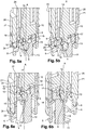
Figure 5a is a partial cross section view of the system showing the interlocking means interlocked with the cylinder body; -
Figure 5b is a partial cross section view of the system showing the interlocking means not interlocked with the cylinder body; -
Figure 6a is a partial cross section view of the system, when the interlocking means are interlocked with the cylinder body and the piston driver is translated along a longitudinal axis; -
Figure 6b is a partial cross section view of the system when the interlocking means are interlocked with the cylinder body -
Figure 7 is a partial cross section of the piston driver and the interlocking means. - A fluid control and processing system 1, partially illustrated in
figures 1 to 7 , according to the present invention comprises acartridge 2 shown infigure 1 . Thecartridge 2 is designed for being operated by an instrument not shown in figures. Thecartridge 2 comprises two cylinder bodies (not represented in figures) being received in thecartridge 2. Each cylinder body presents acylinder interface cylinder interface cartridge 2. Eachcylinder interface figures 1 ,3 ,4 ,5 and 6 ) presenting acircular bearing surface cylinder interface - The fluid control and processing system 1 further comprises dispensing ports, not depicted in figures, to drive at least a fluid flow. Each dispensing port is positioned in order to be connectable with the fluid port, when the instrument is operating the
cartridge 2. - The system further comprises an instrument (not shown in the figures) equipped with a piston driver 8, shown in
figure 2 , designed for operating thecartridge 2. The piston driver 8 depicted infigure 2 has a shape of a shaft extending along an axis A, shown infig. 2 , and presents at one of itstips 9 threepins 10, each extending in a direction perpendicular to the axis A. Eachpin 10 is evenly spaced from theother pins 10 around said axis. - The piston driver 8 is designed for driving a
piston 11, partially shown infigure 6a and 6b . Saidpiston 11 is movable in the cylinder to modulate a fluid volume inside said cylinder to draw or expel a fluid via the fluid port. The piston driver 8 can be connected to thepiston 11 either directly (in an embodiment not shown) or via apiston rod 12 prolonging thepiston 11, partially shown infigures 4a, 4b ,5a, 5b, 6a and 6b . In the present case, the instrument (not shown in the figures) comprises two piston drivers 8 capable of operating the twopistons 11 of thecartridge 2. Each piston driver 8 is designed for being fastened to onepiston 11 in order to move individually each piston 8 around an axis extending along the piston driver 8 fastened to eachpiston 11. Thus, onepiston 11 is movable around an axis A (shown infigure 2 ,4a, 4b ) and the other piston is movable around an axis B (not shown in the figures). - The fluid control and processing system 1 includes reversible fastening means for fastening the
piston 11 to the piston driver 8 in a reversible manner. Said fastening means comprise at least two parts, afirst part 13 located at thetip 9 of thepiston rod 12 and asecond part 14, complementary to thefirst part 13, that comprises thetip 9 and thepins 10 of the piston driver 8, as shown infigure 4a and 4b . - Said fastening means form a bayonet mount as the
first part 13 comprises arecess 16, adapted to receive thetip 9 of the piston driver 8, and three L-shapedgrooves 15 each adapted to receive one of thepins 10. Each L-shapedgroove 15 comprises afirst groove 17 extending along the axis A and asecond groove 18 extending in a plane that is perpendicular to said axis A, seefigures 3, 4a, 4b ,5a, 5b, 6a, 6b . Eachsecond groove 18 is delineated by arim 19 preventing a translation along the axis A of apin 10 engaged in saidsecond groove 18. To fasten the fastening means, thetip 9 of the piston driver 8 is inserted into therecess 16, so that eachpin 10 engages in one of thefirst grooves 17. A rotation around the axis A in a first direction (anticlockwise in the embodiment described in the figures) of the piston driver 8 with respect to thepiston 11, once thetip 9 and thepins 10 are correctly inserted in thefirst part 13, permits to fasten the piston driver 8 to thepiston 11 as thepins 10 engage in thesecond grooves 18 and are blocked in translation along axis A by therims 19. When pins 10 are in thesecond grooves 18, as shown infigure 6a , a translation of thepiston driver 9 in a direction along the axis A causes a translation of thepiston 11 in the same direction. - A rotation of the piston driver 8 with respect to the
piston 11 in a second direction, opposite to the first direction, permits to unfasten thepiston 11 and the piston driver 8. - The fluid control and processing system 1 also comprises rotating means for rotating the cylinder body, and thereby the fluid port, in order to place the fluid port in fluid communication with at least one of the dispensing ports. Said rotating means comprise a
cylinder driver 20, shown infigures 4a, 4b ,5a, 5b ,6a, 6b and7 . Saidcylinder driver 20 comprises a hollow circularcylindrical body 21 defining aninternal space 24 whose shape is adapted to allow the piston driver 8 to translate and rotate inside. Theinternal space 24 presents a cylindrical shape, whose base forms substantially a triangle. Thecylinder driver 20 comprises threeengaging teeth 22,figure 7 , located and designed for being inserted in complementary coupling grooves 23 located in thebearing surface 6, as shown infigures 5a and 5b . When the engagingteeth 22 are inserted into said coupling grooves 23, a rotation of saidcylinder driver 20 around the axis A causes a rotation of thecylinder interface 3 and of the cylinder body, seefigures 6a and 6b . - The fluid control and processing system 1 further comprises interlocking means for interlocking the piston driver 8 and the
cylinder driver 20, so that the rotation of the cylinder body is controllable by the piston driver 8, when the piston driver 8 is fastened to thepiston 11 by the fastening means. Such interlocking means comprises a guide bush 24 (figures 2 to 7 ). Theguide bush 24 presents a hollow extrudedwall 25 whose internal section is adapted for receiving the piston driver 8 with thepins 10 as shown infigure 7 . The external section of the extrudedwall 25 is adapted to form a sliding joint with theinternal space 24 of thecylinder driver 20. Once the piston driver 8 is fastened to thepiston 11 and when thecylinder driver 20 is coupled with the cylinder body via thecylinder interface 3, theguide bush 24 is translated along the axis A to accommodate the cylinder driver 8 and to form a joint with thecylinder driver 20 as shown infigure 7 . In that position, a rotation of theguide bush 24 causes the simultaneous rotation of the piston driver 8 and of thecylinder driver 20.
the fluid control and processing system further comprising:
Claims (9)
- A fluid control and processing system (1) comprising:- a cartridge (2);- an instrument being designed for operating the cartridge (2);- at least a cylinder body being received in the cartridge (2), said at least a cylinder body comprising a cylinder and at least a fluid port in fluid communication with said cylinder;- a piston (11) being movable in translation along an axis A in the cylinder to modulate a fluid volume inside said cylinder;the instrument comprising a piston driver (8), said piston driver (8) being designed for driving the piston (11) in rotation and in translation around and along the axis A;
the fluid control and processing system (1) further comprising:- dispensing ports to drive at least a fluid flow, each dispensing port being positioned to be connectable, when the instrument is operating the cartridge (2), with the at least a fluid port of the cylinder port by rotation of the cylinder body;- reversible fastening means for fastening the piston (11) to the piston driver (8) when the piston driver (8) is rotated with respect to the piston (11) in a first direction around the axis A which extends along the piston driver (8); and said reversible fastening means being designed for unfastening the piston (11) from the piston driver (8) when the piston driver (8) is rotated with respect to the piston (11) in a second direction opposite to the first direction, so that the movement of the piston (11) is controlled by the piston driver (8);- rotating means comprising a cylinder driver (20) constitutive of the instrument for rotating the cylinder body around the axis A, and thereby the fluid port, in order to place the fluid port in fluid communication with at least one of the dispensing ports;- interlocking means (24, 25) for interlocking the piston driver (8) and the cylinder driver (20), so that the rotation of the cylinder body is controllable by the piston driver (8), when the piston driver (8) and the piston (11) are fastened by the fastening means. - A fluid control and processing system (1) according to claim 1, wherein the fastening means comprise at least two parts, a first part (13) and a second part (14), the piston (11) being attached to said first part (13) and the piston driver (14) comprising said second part (14).
- A fluid control and processing system (1) according to claims 1 or 2 wherein when the fastening means fasten the piston (11) with the piston driver (8), a translation of the piston driver (8) in a direction along the axis A causes a translation of the piston (11) in the same direction.
- A fluid and control and processing system (1) according to any one of claims 1 to 3, wherein the cylinder driver (20) is designed for forming a revolute joint with the cylinder body.
- A fluid control and processing system according to any one of claims 1 to 4, wherein the fastening means are designed for fastening the piston (11) with the piston driver (8) when the piston driver (8) is rotated with respect to the piston (11) in a first direction, and are designed for unfastening the piston (11) from the piston driver (8) when the piston driver (8) is rotated with respect to the piston (11) in a second direction opposite to the first direction.
- A fluid control and processing system (1) according to any one of the claims 1 to 5, wherein the fastening means comprise a bayonet mount.
- A fluid control and processing system (1) according to any one of the claims 1 to 6, wherein the interlocking means are designed for preventing the rotation of piston driver (8) with respect to the piston in the second direction.
- A fluid control and processing system according to any one of the claims 1 to 7, wherein it further comprises a prismatic connection between the interlocking means and the piston driver (8) and a clamping joint, between the rotating means and the interlocking means.
- A fluid control and processing system according to any one of claims 1 to 8, wherein the interlocking means further comprises a guide bush (24) so that once the piston driver (8) is fastened to the piston (11) and when the cylinder driver (29) is coupled with the cylinder body, a rotation of the guide bush (24) causes the simultaneous rotation of the piston driver (8) and of the cylinder driver (20).
Priority Applications (2)
| Application Number | Priority Date | Filing Date | Title |
|---|---|---|---|
| EP14719670.3A EP2983823B1 (en) | 2013-04-12 | 2014-04-11 | Manifold driver |
| EP20212378.2A EP3804858A1 (en) | 2013-04-12 | 2014-04-11 | Manifold driver |
Applications Claiming Priority (3)
| Application Number | Priority Date | Filing Date | Title |
|---|---|---|---|
| EP13163554.2A EP2789388A1 (en) | 2013-04-12 | 2013-04-12 | Manifold driver |
| EP14719670.3A EP2983823B1 (en) | 2013-04-12 | 2014-04-11 | Manifold driver |
| PCT/EP2014/057412 WO2014167109A1 (en) | 2013-04-12 | 2014-04-11 | Manifold driver |
Related Child Applications (1)
| Application Number | Title | Priority Date | Filing Date |
|---|---|---|---|
| EP20212378.2A Division EP3804858A1 (en) | 2013-04-12 | 2014-04-11 | Manifold driver |
Publications (2)
| Publication Number | Publication Date |
|---|---|
| EP2983823A1 EP2983823A1 (en) | 2016-02-17 |
| EP2983823B1 true EP2983823B1 (en) | 2020-12-30 |
Family
ID=48139742
Family Applications (3)
| Application Number | Title | Priority Date | Filing Date |
|---|---|---|---|
| EP13163554.2A Withdrawn EP2789388A1 (en) | 2013-04-12 | 2013-04-12 | Manifold driver |
| EP14719670.3A Active EP2983823B1 (en) | 2013-04-12 | 2014-04-11 | Manifold driver |
| EP20212378.2A Withdrawn EP3804858A1 (en) | 2013-04-12 | 2014-04-11 | Manifold driver |
Family Applications Before (1)
| Application Number | Title | Priority Date | Filing Date |
|---|---|---|---|
| EP13163554.2A Withdrawn EP2789388A1 (en) | 2013-04-12 | 2013-04-12 | Manifold driver |
Family Applications After (1)
| Application Number | Title | Priority Date | Filing Date |
|---|---|---|---|
| EP20212378.2A Withdrawn EP3804858A1 (en) | 2013-04-12 | 2014-04-11 | Manifold driver |
Country Status (7)
| Country | Link |
|---|---|
| US (1) | US9939075B2 (en) |
| EP (3) | EP2789388A1 (en) |
| JP (1) | JP6505081B2 (en) |
| CN (1) | CN105142788B (en) |
| CA (1) | CA2907888C (en) |
| ES (1) | ES2853326T3 (en) |
| WO (1) | WO2014167109A1 (en) |
Families Citing this family (2)
| Publication number | Priority date | Publication date | Assignee | Title |
|---|---|---|---|---|
| GB201806505D0 (en) | 2018-04-20 | 2018-06-06 | Q Linea Ab | Analysis instrument and sample preparation cartridge |
| JP7315625B2 (en) * | 2020-07-14 | 2023-07-26 | エッペンドルフ エスイー | Pipettes for use with pipette tips with integral plungers |
Family Cites Families (12)
| Publication number | Priority date | Publication date | Assignee | Title |
|---|---|---|---|---|
| US3273595A (en) * | 1966-09-20 | Novak gas plow control valve | ||
| US3612104A (en) * | 1969-07-25 | 1971-10-12 | Agustin A Busquets | Mixing and diverter water valve |
| US4689204A (en) * | 1985-03-08 | 1987-08-25 | Cambridge Bioscience Corporation | Multiple step reagent delivery system |
| US4653537A (en) * | 1986-03-20 | 1987-03-31 | Water Services Of America, Inc. | Fluid flow diverter valve with improved chamber arrangement |
| WO2001011374A2 (en) * | 1999-08-06 | 2001-02-15 | Thermo Biostar, Inc. | An automated point of care detection system including complete sample processing capabilities |
| US8048386B2 (en) | 2002-02-25 | 2011-11-01 | Cepheid | Fluid processing and control |
| US8171958B2 (en) * | 2007-08-01 | 2012-05-08 | Fmc Technologies, Inc. | Integrated plug/choke valve |
| JP4962575B2 (en) * | 2008-01-07 | 2012-06-27 | 株式会社島津製作所 | Reaction vessel |
| US8905075B2 (en) * | 2009-07-13 | 2014-12-09 | Idex Health & Science Llc | Rotary shear valve assembly with hard-on-hard seal surfaces |
| GB0913903D0 (en) * | 2009-08-10 | 2009-09-16 | Forensic Science Service Ltd | Improvements in and relating to sample handling |
| DE102009040525B4 (en) * | 2009-09-08 | 2015-02-05 | Andreas Hettich Gmbh & Co. Kg | Centrifuge for separating whole blood into blood components, and fluidically communicating containers for insertion into the centrifuge, and methods for obtaining a highly enriched platelet concentrate from whole blood |
| ES2579958T3 (en) * | 2009-10-21 | 2016-08-17 | Biocartis Nv | Manifold for a fluidic cartridge |
-
2013
- 2013-04-12 EP EP13163554.2A patent/EP2789388A1/en not_active Withdrawn
-
2014
- 2014-04-11 US US14/783,582 patent/US9939075B2/en active Active
- 2014-04-11 JP JP2016506995A patent/JP6505081B2/en active Active
- 2014-04-11 EP EP14719670.3A patent/EP2983823B1/en active Active
- 2014-04-11 ES ES14719670T patent/ES2853326T3/en active Active
- 2014-04-11 CN CN201480020816.9A patent/CN105142788B/en active Active
- 2014-04-11 CA CA2907888A patent/CA2907888C/en active Active
- 2014-04-11 EP EP20212378.2A patent/EP3804858A1/en not_active Withdrawn
- 2014-04-11 WO PCT/EP2014/057412 patent/WO2014167109A1/en not_active Ceased
Non-Patent Citations (1)
| Title |
|---|
| None * |
Also Published As
| Publication number | Publication date |
|---|---|
| ES2853326T3 (en) | 2021-09-15 |
| US9939075B2 (en) | 2018-04-10 |
| EP3804858A1 (en) | 2021-04-14 |
| CA2907888C (en) | 2021-03-16 |
| JP2016518597A (en) | 2016-06-23 |
| CN105142788B (en) | 2017-12-19 |
| CA2907888A1 (en) | 2014-10-16 |
| EP2789388A1 (en) | 2014-10-15 |
| EP2983823A1 (en) | 2016-02-17 |
| WO2014167109A1 (en) | 2014-10-16 |
| CN105142788A (en) | 2015-12-09 |
| US20160069464A1 (en) | 2016-03-10 |
| JP6505081B2 (en) | 2019-04-24 |
Similar Documents
| Publication | Publication Date | Title |
|---|---|---|
| US7814805B2 (en) | Automated pipette machine | |
| US7201185B2 (en) | Coupled drive multi-position fluid valve apparatus and method | |
| US8747747B2 (en) | Reader devices for manipulating multi-fluidic cartridges for sample analysis | |
| KR101876586B1 (en) | Fluid delivery system and apparatus to perform the same | |
| EP2803889A1 (en) | Multi-position micro-fluidic valve system with removable encoder assembly | |
| US10953399B2 (en) | Fluid caching | |
| RS61271B1 (en) | System for carrying out reactions | |
| US20110244593A1 (en) | Method and apparatus for selectively admixing reagents in a substantially undiluted biologic fluid sample analysis | |
| US20130064693A1 (en) | Plunger pump for volumes below one microliter, allowing manual intervention | |
| CA2907888C (en) | Manifold driver | |
| US10150119B2 (en) | Rotary sampling valve and device equipped with such a valve | |
| US8915405B2 (en) | Dosing apparatus | |
| EP2577320B1 (en) | Miniaturized syringe pump system and modules | |
| CN115382586B (en) | Driving device and medical detection system | |
| EP3976164B1 (en) | Holding device and apparatus for automated stopcock actuation | |
| CN214571952U (en) | Vertical micro-fluidic core and rotary piston thereof | |
| CN113926499B (en) | Pipette valve, sample handling device and molecular diagnostic system | |
| JP4516824B2 (en) | Multi-channel switching valve | |
| JP4485305B2 (en) | Small volume constant volume injection valve structure | |
| US20050197538A1 (en) | Reagent and sample introduction plunger device for a syringe |
Legal Events
| Date | Code | Title | Description |
|---|---|---|---|
| PUAI | Public reference made under article 153(3) epc to a published international application that has entered the european phase |
Free format text: ORIGINAL CODE: 0009012 |
|
| 17P | Request for examination filed |
Effective date: 20150918 |
|
| AK | Designated contracting states |
Kind code of ref document: A1 Designated state(s): AL AT BE BG CH CY CZ DE DK EE ES FI FR GB GR HR HU IE IS IT LI LT LU LV MC MK MT NL NO PL PT RO RS SE SI SK SM TR |
|
| AX | Request for extension of the european patent |
Extension state: BA ME |
|
| DAX | Request for extension of the european patent (deleted) | ||
| STAA | Information on the status of an ep patent application or granted ep patent |
Free format text: STATUS: EXAMINATION IS IN PROGRESS |
|
| 17Q | First examination report despatched |
Effective date: 20191206 |
|
| GRAP | Despatch of communication of intention to grant a patent |
Free format text: ORIGINAL CODE: EPIDOSNIGR1 |
|
| STAA | Information on the status of an ep patent application or granted ep patent |
Free format text: STATUS: GRANT OF PATENT IS INTENDED |
|
| INTG | Intention to grant announced |
Effective date: 20200714 |
|
| GRAS | Grant fee paid |
Free format text: ORIGINAL CODE: EPIDOSNIGR3 |
|
| GRAA | (expected) grant |
Free format text: ORIGINAL CODE: 0009210 |
|
| STAA | Information on the status of an ep patent application or granted ep patent |
Free format text: STATUS: THE PATENT HAS BEEN GRANTED |
|
| AK | Designated contracting states |
Kind code of ref document: B1 Designated state(s): AL AT BE BG CH CY CZ DE DK EE ES FI FR GB GR HR HU IE IS IT LI LT LU LV MC MK MT NL NO PL PT RO RS SE SI SK SM TR |
|
| REG | Reference to a national code |
Ref country code: GB Ref legal event code: FG4D |
|
| REG | Reference to a national code |
Ref country code: AT Ref legal event code: REF Ref document number: 1349397 Country of ref document: AT Kind code of ref document: T Effective date: 20210115 |
|
| REG | Reference to a national code |
Ref country code: DE Ref legal event code: R096 Ref document number: 602014073776 Country of ref document: DE |
|
| REG | Reference to a national code |
Ref country code: IE Ref legal event code: FG4D |
|
| REG | Reference to a national code |
Ref country code: CH Ref legal event code: NV Representative=s name: VALIPAT S.A. C/O BOVARD SA NEUCHATEL, CH |
|
| REG | Reference to a national code |
Ref country code: NL Ref legal event code: FP |
|
| PG25 | Lapsed in a contracting state [announced via postgrant information from national office to epo] |
Ref country code: GR Free format text: LAPSE BECAUSE OF FAILURE TO SUBMIT A TRANSLATION OF THE DESCRIPTION OR TO PAY THE FEE WITHIN THE PRESCRIBED TIME-LIMIT Effective date: 20210331 Ref country code: RS Free format text: LAPSE BECAUSE OF FAILURE TO SUBMIT A TRANSLATION OF THE DESCRIPTION OR TO PAY THE FEE WITHIN THE PRESCRIBED TIME-LIMIT Effective date: 20201230 Ref country code: FI Free format text: LAPSE BECAUSE OF FAILURE TO SUBMIT A TRANSLATION OF THE DESCRIPTION OR TO PAY THE FEE WITHIN THE PRESCRIBED TIME-LIMIT Effective date: 20201230 Ref country code: NO Free format text: LAPSE BECAUSE OF FAILURE TO SUBMIT A TRANSLATION OF THE DESCRIPTION OR TO PAY THE FEE WITHIN THE PRESCRIBED TIME-LIMIT Effective date: 20210330 |
|
| REG | Reference to a national code |
Ref country code: AT Ref legal event code: MK05 Ref document number: 1349397 Country of ref document: AT Kind code of ref document: T Effective date: 20201230 |
|
| PG25 | Lapsed in a contracting state [announced via postgrant information from national office to epo] |
Ref country code: LV Free format text: LAPSE BECAUSE OF FAILURE TO SUBMIT A TRANSLATION OF THE DESCRIPTION OR TO PAY THE FEE WITHIN THE PRESCRIBED TIME-LIMIT Effective date: 20201230 Ref country code: SE Free format text: LAPSE BECAUSE OF FAILURE TO SUBMIT A TRANSLATION OF THE DESCRIPTION OR TO PAY THE FEE WITHIN THE PRESCRIBED TIME-LIMIT Effective date: 20201230 Ref country code: BG Free format text: LAPSE BECAUSE OF FAILURE TO SUBMIT A TRANSLATION OF THE DESCRIPTION OR TO PAY THE FEE WITHIN THE PRESCRIBED TIME-LIMIT Effective date: 20210330 |
|
| PG25 | Lapsed in a contracting state [announced via postgrant information from national office to epo] |
Ref country code: HR Free format text: LAPSE BECAUSE OF FAILURE TO SUBMIT A TRANSLATION OF THE DESCRIPTION OR TO PAY THE FEE WITHIN THE PRESCRIBED TIME-LIMIT Effective date: 20201230 |
|
| REG | Reference to a national code |
Ref country code: LT Ref legal event code: MG9D |
|
| PG25 | Lapsed in a contracting state [announced via postgrant information from national office to epo] |
Ref country code: LT Free format text: LAPSE BECAUSE OF FAILURE TO SUBMIT A TRANSLATION OF THE DESCRIPTION OR TO PAY THE FEE WITHIN THE PRESCRIBED TIME-LIMIT Effective date: 20201230 Ref country code: SK Free format text: LAPSE BECAUSE OF FAILURE TO SUBMIT A TRANSLATION OF THE DESCRIPTION OR TO PAY THE FEE WITHIN THE PRESCRIBED TIME-LIMIT Effective date: 20201230 Ref country code: PT Free format text: LAPSE BECAUSE OF FAILURE TO SUBMIT A TRANSLATION OF THE DESCRIPTION OR TO PAY THE FEE WITHIN THE PRESCRIBED TIME-LIMIT Effective date: 20210430 Ref country code: RO Free format text: LAPSE BECAUSE OF FAILURE TO SUBMIT A TRANSLATION OF THE DESCRIPTION OR TO PAY THE FEE WITHIN THE PRESCRIBED TIME-LIMIT Effective date: 20201230 Ref country code: CZ Free format text: LAPSE BECAUSE OF FAILURE TO SUBMIT A TRANSLATION OF THE DESCRIPTION OR TO PAY THE FEE WITHIN THE PRESCRIBED TIME-LIMIT Effective date: 20201230 Ref country code: EE Free format text: LAPSE BECAUSE OF FAILURE TO SUBMIT A TRANSLATION OF THE DESCRIPTION OR TO PAY THE FEE WITHIN THE PRESCRIBED TIME-LIMIT Effective date: 20201230 |
|
| PG25 | Lapsed in a contracting state [announced via postgrant information from national office to epo] |
Ref country code: PL Free format text: LAPSE BECAUSE OF FAILURE TO SUBMIT A TRANSLATION OF THE DESCRIPTION OR TO PAY THE FEE WITHIN THE PRESCRIBED TIME-LIMIT Effective date: 20201230 Ref country code: AT Free format text: LAPSE BECAUSE OF FAILURE TO SUBMIT A TRANSLATION OF THE DESCRIPTION OR TO PAY THE FEE WITHIN THE PRESCRIBED TIME-LIMIT Effective date: 20201230 |
|
| REG | Reference to a national code |
Ref country code: ES Ref legal event code: FG2A Ref document number: 2853326 Country of ref document: ES Kind code of ref document: T3 Effective date: 20210915 |
|
| PG25 | Lapsed in a contracting state [announced via postgrant information from national office to epo] |
Ref country code: IS Free format text: LAPSE BECAUSE OF FAILURE TO SUBMIT A TRANSLATION OF THE DESCRIPTION OR TO PAY THE FEE WITHIN THE PRESCRIBED TIME-LIMIT Effective date: 20210430 |
|
| REG | Reference to a national code |
Ref country code: DE Ref legal event code: R097 Ref document number: 602014073776 Country of ref document: DE |
|
| PG25 | Lapsed in a contracting state [announced via postgrant information from national office to epo] |
Ref country code: AL Free format text: LAPSE BECAUSE OF FAILURE TO SUBMIT A TRANSLATION OF THE DESCRIPTION OR TO PAY THE FEE WITHIN THE PRESCRIBED TIME-LIMIT Effective date: 20201230 |
|
| PLBE | No opposition filed within time limit |
Free format text: ORIGINAL CODE: 0009261 |
|
| STAA | Information on the status of an ep patent application or granted ep patent |
Free format text: STATUS: NO OPPOSITION FILED WITHIN TIME LIMIT |
|
| PG25 | Lapsed in a contracting state [announced via postgrant information from national office to epo] |
Ref country code: MC Free format text: LAPSE BECAUSE OF FAILURE TO SUBMIT A TRANSLATION OF THE DESCRIPTION OR TO PAY THE FEE WITHIN THE PRESCRIBED TIME-LIMIT Effective date: 20201230 Ref country code: DK Free format text: LAPSE BECAUSE OF FAILURE TO SUBMIT A TRANSLATION OF THE DESCRIPTION OR TO PAY THE FEE WITHIN THE PRESCRIBED TIME-LIMIT Effective date: 20201230 |
|
| 26N | No opposition filed |
Effective date: 20211001 |
|
| PG25 | Lapsed in a contracting state [announced via postgrant information from national office to epo] |
Ref country code: LU Free format text: LAPSE BECAUSE OF NON-PAYMENT OF DUE FEES Effective date: 20210411 |
|
| PG25 | Lapsed in a contracting state [announced via postgrant information from national office to epo] |
Ref country code: SI Free format text: LAPSE BECAUSE OF FAILURE TO SUBMIT A TRANSLATION OF THE DESCRIPTION OR TO PAY THE FEE WITHIN THE PRESCRIBED TIME-LIMIT Effective date: 20201230 |
|
| PG25 | Lapsed in a contracting state [announced via postgrant information from national office to epo] |
Ref country code: IE Free format text: LAPSE BECAUSE OF NON-PAYMENT OF DUE FEES Effective date: 20210411 |
|
| PG25 | Lapsed in a contracting state [announced via postgrant information from national office to epo] |
Ref country code: IS Free format text: LAPSE BECAUSE OF FAILURE TO SUBMIT A TRANSLATION OF THE DESCRIPTION OR TO PAY THE FEE WITHIN THE PRESCRIBED TIME-LIMIT Effective date: 20210430 |
|
| REG | Reference to a national code |
Ref country code: GB Ref legal event code: 732E Free format text: REGISTERED BETWEEN 20221117 AND 20221123 |
|
| REG | Reference to a national code |
Ref country code: BE Ref legal event code: RC Free format text: DETAILS PLEDGE: RIGHT OF PLEDGE, ESTABLISHED Name of requester: GLAS TRUST CORPORATION LIMITED Effective date: 20221214 |
|
| PG25 | Lapsed in a contracting state [announced via postgrant information from national office to epo] |
Ref country code: HU Free format text: LAPSE BECAUSE OF FAILURE TO SUBMIT A TRANSLATION OF THE DESCRIPTION OR TO PAY THE FEE WITHIN THE PRESCRIBED TIME-LIMIT; INVALID AB INITIO Effective date: 20140411 |
|
| P01 | Opt-out of the competence of the unified patent court (upc) registered |
Effective date: 20230515 |
|
| PG25 | Lapsed in a contracting state [announced via postgrant information from national office to epo] |
Ref country code: CY Free format text: LAPSE BECAUSE OF FAILURE TO SUBMIT A TRANSLATION OF THE DESCRIPTION OR TO PAY THE FEE WITHIN THE PRESCRIBED TIME-LIMIT Effective date: 20201230 |
|
| PG25 | Lapsed in a contracting state [announced via postgrant information from national office to epo] |
Ref country code: SM Free format text: LAPSE BECAUSE OF FAILURE TO SUBMIT A TRANSLATION OF THE DESCRIPTION OR TO PAY THE FEE WITHIN THE PRESCRIBED TIME-LIMIT Effective date: 20201230 |
|
| PG25 | Lapsed in a contracting state [announced via postgrant information from national office to epo] |
Ref country code: MK Free format text: LAPSE BECAUSE OF FAILURE TO SUBMIT A TRANSLATION OF THE DESCRIPTION OR TO PAY THE FEE WITHIN THE PRESCRIBED TIME-LIMIT Effective date: 20201230 |
|
| PG25 | Lapsed in a contracting state [announced via postgrant information from national office to epo] |
Ref country code: MT Free format text: LAPSE BECAUSE OF FAILURE TO SUBMIT A TRANSLATION OF THE DESCRIPTION OR TO PAY THE FEE WITHIN THE PRESCRIBED TIME-LIMIT Effective date: 20201230 |
|
| PGFP | Annual fee paid to national office [announced via postgrant information from national office to epo] |
Ref country code: NL Payment date: 20250423 Year of fee payment: 12 |
|
| PGFP | Annual fee paid to national office [announced via postgrant information from national office to epo] |
Ref country code: DE Payment date: 20250417 Year of fee payment: 12 |
|
| PGFP | Annual fee paid to national office [announced via postgrant information from national office to epo] |
Ref country code: GB Payment date: 20250424 Year of fee payment: 12 Ref country code: ES Payment date: 20250519 Year of fee payment: 12 |
|
| PGFP | Annual fee paid to national office [announced via postgrant information from national office to epo] |
Ref country code: IT Payment date: 20250430 Year of fee payment: 12 Ref country code: BE Payment date: 20250417 Year of fee payment: 12 |
|
| PGFP | Annual fee paid to national office [announced via postgrant information from national office to epo] |
Ref country code: FR Payment date: 20250428 Year of fee payment: 12 |
|
| PGFP | Annual fee paid to national office [announced via postgrant information from national office to epo] |
Ref country code: CH Payment date: 20250501 Year of fee payment: 12 |
|
| PG25 | Lapsed in a contracting state [announced via postgrant information from national office to epo] |
Ref country code: TR Free format text: LAPSE BECAUSE OF FAILURE TO SUBMIT A TRANSLATION OF THE DESCRIPTION OR TO PAY THE FEE WITHIN THE PRESCRIBED TIME-LIMIT Effective date: 20201230 |
|
| REG | Reference to a national code |
Ref country code: CH Ref legal event code: U11 Free format text: ST27 STATUS EVENT CODE: U-0-0-U10-U11 (AS PROVIDED BY THE NATIONAL OFFICE) Effective date: 20260501 |