EP2983251A1 - Connector - Google Patents
Connector Download PDFInfo
- Publication number
- EP2983251A1 EP2983251A1 EP14778672.7A EP14778672A EP2983251A1 EP 2983251 A1 EP2983251 A1 EP 2983251A1 EP 14778672 A EP14778672 A EP 14778672A EP 2983251 A1 EP2983251 A1 EP 2983251A1
- Authority
- EP
- European Patent Office
- Prior art keywords
- terminal accommodating
- connector
- receptacle
- wire
- accommodating portion
- Prior art date
- Legal status (The legal status is an assumption and is not a legal conclusion. Google has not performed a legal analysis and makes no representation as to the accuracy of the status listed.)
- Withdrawn
Links
Images





Classifications
-
- H—ELECTRICITY
- H01—ELECTRIC ELEMENTS
- H01R—ELECTRICALLY-CONDUCTIVE CONNECTIONS; STRUCTURAL ASSOCIATIONS OF A PLURALITY OF MUTUALLY-INSULATED ELECTRICAL CONNECTING ELEMENTS; COUPLING DEVICES; CURRENT COLLECTORS
- H01R13/00—Details of coupling devices of the kinds covered by groups H01R12/70 or H01R24/00 - H01R33/00
- H01R13/46—Bases; Cases
- H01R13/514—Bases; Cases composed as a modular blocks or assembly, i.e. composed of co-operating parts provided with contact members or holding contact members between them
-
- H—ELECTRICITY
- H01—ELECTRIC ELEMENTS
- H01R—ELECTRICALLY-CONDUCTIVE CONNECTIONS; STRUCTURAL ASSOCIATIONS OF A PLURALITY OF MUTUALLY-INSULATED ELECTRICAL CONNECTING ELEMENTS; COUPLING DEVICES; CURRENT COLLECTORS
- H01R13/00—Details of coupling devices of the kinds covered by groups H01R12/70 or H01R24/00 - H01R33/00
- H01R13/62—Means for facilitating engagement or disengagement of coupling parts or for holding them in engagement
- H01R13/629—Additional means for facilitating engagement or disengagement of coupling parts, e.g. aligning or guiding means, levers, gas pressure electrical locking indicators, manufacturing tolerances
- H01R13/631—Additional means for facilitating engagement or disengagement of coupling parts, e.g. aligning or guiding means, levers, gas pressure electrical locking indicators, manufacturing tolerances for engagement only
-
- H—ELECTRICITY
- H01—ELECTRIC ELEMENTS
- H01R—ELECTRICALLY-CONDUCTIVE CONNECTIONS; STRUCTURAL ASSOCIATIONS OF A PLURALITY OF MUTUALLY-INSULATED ELECTRICAL CONNECTING ELEMENTS; COUPLING DEVICES; CURRENT COLLECTORS
- H01R13/00—Details of coupling devices of the kinds covered by groups H01R12/70 or H01R24/00 - H01R33/00
- H01R13/62—Means for facilitating engagement or disengagement of coupling parts or for holding them in engagement
- H01R13/629—Additional means for facilitating engagement or disengagement of coupling parts, e.g. aligning or guiding means, levers, gas pressure electrical locking indicators, manufacturing tolerances
- H01R13/631—Additional means for facilitating engagement or disengagement of coupling parts, e.g. aligning or guiding means, levers, gas pressure electrical locking indicators, manufacturing tolerances for engagement only
- H01R13/6315—Additional means for facilitating engagement or disengagement of coupling parts, e.g. aligning or guiding means, levers, gas pressure electrical locking indicators, manufacturing tolerances for engagement only allowing relative movement between coupling parts, e.g. floating connection
Definitions
- the present invention relates to a connector.
- these devices may be used while being stacked.
- a plurality of connectors may also be stacked on the same side.
- Connectors need to be connected in view of a stacking tolerance in stacking a plurality of connectors, but there has been a problem of being very difficult to connect connectors connected to devices (device-side connectors) in view of the stacking tolerance.
- Patent literature 1 is a patent literature 1
- the terminal accommodating portions may be inclined without taking a proper connection posture when the wire-side connector is connected to a device-side connector.
- the terminal accommodating portions and receptacles of the device-side connector interfere and a connecting operation cannot be performed.
- the terminal accommodating portions and the corresponding device-side receptacles need to be positioned prior to the connecting operation, which has presented a problem of poor operation efficiency.
- the present invention was completed based on the above situation and aims to improve operation efficiency in connecting a device-side connector and a wire-side connector.
- the present invention was achieved as a result of intensive studies on a configuration for improving the efficiency of a connecting operation while suppressing the enlargement of device-side receptacles.
- the present invention is directed to a connector with a device-side connector provided on a device side and a wire-side connector provided on a wire side and to be connected to the device-side connector
- the device-side connector includes a device-side receptacle group formed by stacking a plurality of device-side receptacles having an opening on a front side in a connecting direction
- the wire-side connector includes a plurality of wire-side terminals, a plurality of terminal accommodating portions configured to respectively accommodate the wire-side terminals and to be individually accommodated into the device-side receptacles when the device-side connector and the wire-side connector are connected, and an accommodation case configured to hold the plurality of terminal accommodating portions movably in a direction intersecting with the connecting direction
- the opening of an end device-side receptacle arranged on one end part out of the plurality of device-side receptacles includes a guiding protrusion receptacles projecting in the stacking direction and configured to guide
- the opening of the end device-side receptacle arranged on the one end part includes the guiding protrusion projecting in the stacking direction and configured to guide the corresponding terminal accommodating portion in the proper connection posture into the end device-side receptacle, whereas the accommodation case includes the receiving portion configured to receive the guiding protrusion.
- the corresponding terminal accommodating portion is guided into the end device-side receptacle while being corrected into the proper connection posture by the guiding protrusion provided on the opening of the end device-side receptacle even if the terminal accommodating portion is inclined in a direction intersecting with the connecting direction.
- the device-side receptacles are enlarged only by a projecting dimension of the guiding protrusion in the present invention, enlargement can be suppressed more than in the case of considering the inclination of the terminal accommodating portions.
- operation efficiency in connecting the device-side connector and the wire-side connector can be improved more than before while the enlargement of the device-side receptacles is suppressed.
- the present invention may be configured as follows.
- the end device-side receptacle may include a guide groove configured to guide the terminal accommodating portion guided by the guiding protrusion into the device-side receptacle, whereas the corresponding terminal accommodating portion may include a guide protrusion formed to project in an outward direction from a wall portion constituting the terminal accommodating portion and to be guided by the guide groove of the end device-side receptacle.
- the guide protrusion of the terminal accommodating portion is guided into the device-side receptacle by the guide groove of the end device-side receptacle after the terminal accommodating portion corresponding to the end device-side receptacle is corrected into the proper connection posture by the guiding protrusion of the end device-side receptacle, wherefore operation efficiency in connection can be reliably improved.
- Each of the plurality of device-side receptacles may include a guiding portion configured to guide the terminal accommodating portion in a proper connection posture into the corresponding device-side receptacle, whereas each of the plurality of terminal accommodating portions may include a guided portion to be guided by the guiding portion of the device-side receptacle.
- a connector 10 of this embodiment includes a wire-side connector 11 and a device-side connector 30 connectable to each other.
- the device-side connector 30 is a connector provided on a device-side where flat devices such as batteries and substrates are stacked.
- the wire-side connector 11 is a connector connected to ends of wires W such as a voltage detection line and a power line. Note that, in the following description, a connecting direction of the both connectors 11, 30 is referred to as a front-back direction and connection surface sides thereof are referred to as front sides.
- the wire-side connector 11 includes four (plural) terminal accommodating portions 20, wire-side terminals 17 accommodated in the respective terminal accommodating portions 20 and an accommodation case 12 for accommodating the plurality of terminal accommodating portions 20.
- the wire-side terminal 17 includes a wire connecting portion 17A to be connected to an end of the wire W and a terminal connecting portion 17B to be connected to a device-side terminal 37.
- the terminal connecting portion 17B is in the form of a rectangular tube with open front and rear ends and a resilient contact piece is formed inside.
- the device-side terminal 37 is insertable into an opening on the front end of the terminal connecting portion 17B and the resilient contact piece is deflected and deformed to resiliently come into contact with the device-side terminal 37, whereby the both terminals 17, 37 are electrically conductively connected.
- a front side of the accommodation case 12 is open as shown in FIG. 7 , and holding recesses 16A, 16B capable of holding the plurality of terminal accommodating portions 20 side by side are provided on edge parts of a back wall 15 of the accommodation case 12 as shown in FIG. 1 .
- a first holding recess 16A formed on a left edge part of FIG. 1 is shaped to be able to receive a holding piece 21 of the terminal accommodating portion 20 arranged on a left side in FIG. 1 .
- Second holding recesses 16B formed on a pair of side edge parts extending along an arrangement direction of the terminal accommodating portions 20 (lateral direction of FIG. 1 ) out of the edge parts of the back wall 15 of the accommodation case 12 are shaped to be able to receive holding arms 22 of the terminal accommodating portions 20.
- a receiving portion 13 for receiving a guiding protrusion 42 of a device-side receptacle 36A on one end part to be described later is provided inside the accommodation case 12.
- a state where a wall on a front surface side of the accommodation case 12 and a wall covering a front surface side of a device-side receptacle group 35 (wall on a front surface side of the device-side connector 30) out of a device-side covering portion 33A are removed is shown to make conditions of the terminal accommodating portions 20 and the device-side receptacles 36 comprehensive.
- the device-side receptacle 36A on one end part and the other device-side receptacles 36B are referred to as an "end device-side receptacle 36A" and “other device-side receptacles 36B" when they are distinguished.
- the plurality of terminal accommodating portions 20 are held in the accommodation case 12 in a state movable in a direction (stacking direction in this embodiment) intersecting with a connecting direction (vertical direction of FIG. 7 ).
- Clearances C are provided between adjacent terminal accommodating portions 20 and between the terminal accommodating portions 20 and the accommodation case 12 as shown in FIG. 7 , whereby each terminal accommodating portion 20 is movable in the direction intersecting with the connecting direction.
- the terminal accommodating portions 20 move in the direction intersecting with the connecting direction, whereby a stacking tolerance in the device-side connector 30 is absorbed.
- Each terminal accommodating portion 20 is formed to project forward from the back wall 15. As shown in FIG. 3 , the wire-side terminal 17 can be accommodated into the terminal accommodating portion 20. When the wire-side terminal 17 is inserted into the terminal accommodating portion 20, a locking lance (not shown) provided in the terminal accommodating portion 20 is fitted into a lance hole (not shown) provided on the wire-side terminal 17 to retain the wire-side terminal 17.
- the holding piece 21 projecting outwardly is formed on a left edge of a rear end part of each terminal accommodating portion 20 in FIG. 6 .
- a holding piece receiving portion 23 capable of receiving the holding piece 21 of the adjacent terminal accommodating portion 20 is formed on a right edge of the rear end part of each terminal accommodating portion 20 in FIG. 6 , and a pair of holding arms 22 to be received into the holding recesses 16B are formed to project in a direction substantially perpendicular to the arrangement direction of the terminal accommodating portions 20 from opposite sides of the holding piece receiving portion 23.
- a tapered inclined surface 26 is formed on a front end part of the terminal accommodating portion 20 as shown in FIG. 8 and the terminal accommodating portion 20 is smoothly insertable into the device-side receptacle 36 during connection to the device-side connector 30.
- a guide protrusion 27 (example of a guided portion) protruding outwardly in a width direction is provided on a side wall 20A arranged on a front side shown in FIG 8 out of wall portions constituting the terminal accommodating portion 20.
- the terminal accommodating portion 20 is guided to take a proper connection posture by the contact of the guide protrusion 27 with an inclined surface 43 of the guiding protrusion 42 of the end device-side receptacle 36B or an inclined surface 39 (example of a guiding portion) of the other device-side receptacle 36B and the terminal accommodating portion 20 is fitted and guided by the insertion of the guide protrusion 27 into a guide groove 40 (example of the guiding portion) of the device-side receptacle 36.
- the plurality of terminal accommodating portions 20 are successively accommodated into the accommodation case 12 from a left side of FIG. 8 .
- the terminal accommodating portion 20 arranged on the left end is inserted downwardly from above in FIG. 8 in a state where the holding piece 21 thereof is positioned to correspond to the first holding recess 16A of the accommodation case 12 and the holding arms 22 are positioned to correspond to the second holding recesses 16B.
- the second terminal accommodating portion 20 and the third terminal accommodating portion 20 from left are successively inserted.
- the second terminal accommodating portion 20 and the third terminal accommodating portion 20 from left are inserted downwardly from above in FIG. 8 in a state where the holding pieces 21 thereof are positioned to correspond to the holding piece receiving portions 23 of the adjacent terminal accommodating portions 20 and the holding arms 22 are positioned to correspond to the second holding recesses 16B.
- the device-side connector 30 is composed of a plurality of split connectors 32 provided for each device.
- the plurality of split connectors 32 are collectively covered in a stacked state by a device-side case 33.
- a part of the device-side case 33 covering the device-side receptacle group 35 serves as the device-side covering portion 33A.
- Each split connector 32 includes the device-side receptacle 36 and the device-side terminal 37 (see FIG. 3 ).
- a plurality of stacked device-side receptacles 36 of the split connectors 32 are referred to as the device-side receptacle group 35.
- the device-side terminal 37 is provided to project forward from a back wall of the device-side receptacle 36.
- Two inclined surfaces 39 are respectively formed on a shown upper end of a wall 38 arranged on a front surface side of each of four (plural) device-side receptacles 36 to have a tapered upper end side (front end side in the connecting direction) as shown in FIG. 8 .
- the wall 38 arranged on the front surface side of each device-side receptacle 36 is formed with a slit-like guide groove 40 connected to one inclined surface 39 and extending in the connecting direction.
- the guide protrusion 27 of the terminal accommodating portion 20 is fitted into the guide groove 40 to fit and guide the terminal accommodating portion 20 into the device-side receptacle 36.
- the guiding protrusion 42 is provided on the end device-side receptacle 36A arranged on the left end part shown in FIG. 5 .
- the guiding protrusion 42 is formed to project in the stacking direction (lateral direction as shown) in an opening 36C of the end device-side receptacle 36A and has a function of guiding the corresponding terminal accommodating portion 20 (terminal accommodating portion 20 on the left end in FIG. 5 ) in the proper connection posture into the end device-side receptacle 36A.
- the guiding protrusion 42 projects in the stacking direction as shown in FIG. 3 , it is accommodated into the receiving portion 13 of the accommodation case 12.
- the guiding protrusion 42 is formed with the inclined surface 43 inclined in a direction to enlarge the opening 36C toward the upper end of the opening 36C as shown in FIG. 3 .
- the terminal accommodating portion 20 arranged on the end part is corrected into the proper connection posture by making a sliding movement after the guide protrusion 27 of this terminal accommodating portion 20 comes into contact with the inclined surface 43 of the guiding protrusion 42. Since the guide groove 40 is provided to be connected to the inclined surface 43 of the guiding protrusion 42 in this embodiment, the guide protrusion 27 of the terminal accommodating portion 20 corrected into the proper connection posture by the inclined surface 43 of the guiding protrusion 42 is fitted into the guide groove 40 and the terminal accommodating portion 20 is fitted and guided into the end device-side receptacle 36A.
- the wire-side connector 11 is prepared by accommodating the wire-side terminals 17 connected to the wires W into the terminal accommodating portions 20 after the four terminal accommodating portions 20 are successively accommodated into the accommodation case 12 from the end.
- the four split connectors 32 constituting the device-side connector 30 are stacked to prepare the device-side connector 30 in the stacked state.
- the device-side case 33 is mounted on the device-side connector 30 in the stacked state prepared in this way.
- the device-side connector 30 and the wire-side connector 11 are connected. If the terminal accommodating portions 20 of the wire-side connector 11 are in the proper connection posture, the wire-side connector 11 and the device-side connector 30 can be smoothly connected without requiring positioning and the like.
- the terminal accommodating portions 20 of the wire-side connector 11 may be, for example, postured to be inclined rightwardly in FIG. 7 . If the wire-side connector 11 and the device-side connector 30 are connected in such a case, the guide protrusion 27 of the terminal accommodating portion 20 arranged on the end part comes into contact with the guiding protrusion 42 of the end device-side receptacle 36A and the guide protrusions 27 of the other terminal accommodating portions 20 come into contact with end parts of the openings 36C of the other device-side receptacles 36B (see FIG. 11 ).
- the guide protrusion 27 of the terminal accommodating portion 20 brought into contact with the guiding protrusion 42 of the end device-side receptacle 36A is guided by the inclined surface 43 of the guiding protrusion 42, whereby the terminal accommodating portion 20 is corrected into the proper connection posture.
- the guide protrusion 27 of each terminal accommodating portion 20 brought into contact with the end part (shown upper end part) of the opening 36C of the other device-side receptacle 36B is guided by the inclined surface 39 formed on the opening 36C of the other device-side receptacle 36B, whereby each terminal accommodating portion 20 is corrected into the proper connection posture.
- the guide protrusion 27 of each terminal accommodating portion 20 smoothly moves along the guide groove 40 (along the connecting direction), whereby the wire-side connector 11 is guided to be connected.
- the wire-side connector 11 and the device-side connector 30 are properly connected as shown in FIGS. 1 and 5 , the wire-side terminals 17 and the device-side terminals 37 are in a state electrically connectable to each other.
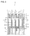
- the guiding protrusion 42 provided on the end device-side receptacle 36A is received into the receiving portion 13 of the accommodation case 12 (see FIG. 3 ).
- the opening 36c of the end device-side receptacle 36A arranged on the one end part is provided with the guiding protrusion 42 projecting in the stacking direction and configured to guide the corresponding terminal accommodating portion 20 in the proper connection posture into the end device-side receptacle 36A, whereas the accommodation case 12 is provided with the receiving portion 13 configured to receive the guiding protrusion 42.
- the corresponding terminal accommodating portion 20 is guided into the end device-side receptacle 36A while being corrected into the proper connection posture by the guiding protrusion 42 provided on the opening 36C of the end device-side receptacle 36A, for example, even if the terminal accommodating portion 20 is inclined in the stacking direction.
- the guiding protrusion 42 is provided only on one end device-side receptacle 36A, the device-side receptacles 36 are enlarged only by a projecting dimension of the guiding protrusion 42 and the enlargement of the device-side receptacles 36 can be suppressed more than in the case of considering the inclination of the terminal accommodating portions 20.
- operation efficiency in connecting the device-side connector 30 and the wire-side connector 11 can be improved more than before while the enlargement of the device-side receptacles 36A, 36B is suppressed.
- the end device-side receptacle 36A is provided with the guide groove 40 configured to guide the terminal accommodating portion 20 guided by the guiding protrusion 42 into the end device-side receptacle 36A, whereas the corresponding terminal accommodating portion 20 is provided with the guide protrusion 27 formed to project in an outward direction from the wall portion constituting the terminal accommodating portion 20 and to be guided by the guide groove 40 of the end device-side receptacle 36A.
- the guide protrusion 27 of the terminal accommodating portion 20 is guided into the device-side receptacle 36A, 36B by the guide groove 40 of the end device-side receptacle 36A after the terminal accommodating portion 20 corresponding to the end device-side receptacle 36A is corrected into the proper connection posture by the guiding protrusion 42 of the end device-side receptacle 36A, wherefore operation efficiency in connection can be reliably improved.
- each device-side receptacle 36 is provided with the inclined surfaces 39 and the guide groove 40 (guiding portion) for guiding the terminal accommodating portion 20 in the proper connection posture into the corresponding device-side receptacle 36, whereas each terminal accommodating portion 20 is provided with the guide protrusion 27 to be guided by the inclined surfaces 39 and the guide groove 40 of the device-side receptacle 36.
- the terminal accommodating portion 20 corresponding to the end device-side receptacle 36A but also the other terminal accommodating portions 36B are guided into the device-side receptacles 36 while being corrected into the proper connection posture. Therefore, operation efficiency in connecting the device-side connector 30 and the wire-side connector 11 can be further improved.
- the end device-side receptacle may be formed with no guide groove and the terminal accommodating portion may be formed with no guide protrusion.
Landscapes
- Connector Housings Or Holding Contact Members (AREA)
- Details Of Connecting Devices For Male And Female Coupling (AREA)
Abstract
Description
- The present invention relates to a connector.
- In the case of using a plurality of similarly configured devices side by side, these devices may be used while being stacked. In such a case, a plurality of connectors may also be stacked on the same side.
- Connectors need to be connected in view of a stacking tolerance in stacking a plurality of connectors, but there has been a problem of being very difficult to connect connectors connected to devices (device-side connectors) in view of the stacking tolerance.
- To solve such a problem, it has been proposed, for example, in patent literature 1 that a manufacturing tolerance of a device side can be absorbed by providing a clearance between a plurality of terminal accommodating portions and an accommodation case for accommodating the terminal accommodating portions in a wire-side connector to be connected to a device-side connector and making the terminal accommodating portions movable relative to the accommodation case.
- Patent literature 1:
- Japanese Unexamined Patent Publication No.
2012-226882 - However, in a wire-side connector configured such that a plurality of terminal accommodating portions are movable relative to an accommodation case as described in the above patent literature 1, the terminal accommodating portions may be inclined without taking a proper connection posture when the wire-side connector is connected to a device-side connector.
- If an attempt is made to connect the wire-side connector including the terminal accommodating portions in an inclined state and the device-side connector, the terminal accommodating portions and receptacles of the device-side connector interfere and a connecting operation cannot be performed. In such a case, the terminal accommodating portions and the corresponding device-side receptacles need to be positioned prior to the connecting operation, which has presented a problem of poor operation efficiency.
- The present invention was completed based on the above situation and aims to improve operation efficiency in connecting a device-side connector and a wire-side connector.
- To improve the efficiency of a connecting operation of a device-side connector and a wire-side connector, it is considered to avoid the interference between device-side receptacles and terminal accommodating portions by making the device-side receptacles larger. In this case, there has been a problem of enlarging the device-side receptacles since the size of the device-side receptacles needs to be set in consideration of the inclination of the terminal accommodating portions. If the device-side receptacles are enlarged, an accommodation case of the wire-side connector for receiving the device-side receptacles needs to be enlarged.
- The present invention was achieved as a result of intensive studies on a configuration for improving the efficiency of a connecting operation while suppressing the enlargement of device-side receptacles.
- Specifically, the present invention is directed to a connector with a device-side connector provided on a device side and a wire-side connector provided on a wire side and to be connected to the device-side connector, wherein the device-side connector includes a device-side receptacle group formed by stacking a plurality of device-side receptacles having an opening on a front side in a connecting direction, the wire-side connector includes a plurality of wire-side terminals, a plurality of terminal accommodating portions configured to respectively accommodate the wire-side terminals and to be individually accommodated into the device-side receptacles when the device-side connector and the wire-side connector are connected, and an accommodation case configured to hold the plurality of terminal accommodating portions movably in a direction intersecting with the connecting direction, and the opening of an end device-side receptacle arranged on one end part out of the plurality of device-side receptacles includes a guiding protrusion receptacles projecting in the stacking direction and configured to guide the corresponding terminal accommodating portion in a proper connection posture into the end device-side receptacle, whereas the accommodation case includes a receiving portion configured to receive the guiding protrusion.
- In the present invention, the opening of the end device-side receptacle arranged on the one end part includes the guiding protrusion projecting in the stacking direction and configured to guide the corresponding terminal accommodating portion in the proper connection posture into the end device-side receptacle, whereas the accommodation case includes the receiving portion configured to receive the guiding protrusion.
- Accordingly, in the present invention, the corresponding terminal accommodating portion is guided into the end device-side receptacle while being corrected into the proper connection posture by the guiding protrusion provided on the opening of the end device-side receptacle even if the terminal accommodating portion is inclined in a direction intersecting with the connecting direction.
- Further, since the device-side receptacles are enlarged only by a projecting dimension of the guiding protrusion in the present invention, enlargement can be suppressed more than in the case of considering the inclination of the terminal accommodating portions. As a result, according to the present invention, operation efficiency in connecting the device-side connector and the wire-side connector can be improved more than before while the enlargement of the device-side receptacles is suppressed.
- The present invention may be configured as follows.
- The end device-side receptacle may include a guide groove configured to guide the terminal accommodating portion guided by the guiding protrusion into the device-side receptacle, whereas the corresponding terminal accommodating portion may include a guide protrusion formed to project in an outward direction from a wall portion constituting the terminal accommodating portion and to be guided by the guide groove of the end device-side receptacle.
- If such a configuration is adopted, the guide protrusion of the terminal accommodating portion is guided into the device-side receptacle by the guide groove of the end device-side receptacle after the terminal accommodating portion corresponding to the end device-side receptacle is corrected into the proper connection posture by the guiding protrusion of the end device-side receptacle, wherefore operation efficiency in connection can be reliably improved.
- Each of the plurality of device-side receptacles may include a guiding portion configured to guide the terminal accommodating portion in a proper connection posture into the corresponding device-side receptacle, whereas each of the plurality of terminal accommodating portions may include a guided portion to be guided by the guiding portion of the device-side receptacle.
- If such a configuration is adopted, not only the terminal accommodating portion corresponding to the end device-side receptacle, but also the other terminal accommodating portions are guided into the device-side receptacles while being corrected into the proper connection posture. Therefore, operation efficiency in connecting the device-side connector and the wire-side connector can be further improved.
- According to the present invention, it is possible to improve operation efficiency in connecting a device-side connector and a wire-side connector.
-
-
FIG. 1 is a perspective view of a connector according to an embodiment, -
FIG. 2 is a side view of the connector, -
FIG. 3 is a section along A-A ofFIG. 2 , -
FIG. 4 is a section along B-B ofFIG. 3 , -
FIG. 5 is a perspective view of the connector showing a state where a wall on a front surface side of an accommodation case and a wall on a front surface side of a device-side connector are removed, -
FIG. 6 is a perspective view of the device-side connector and a wire-side connector in a separated state, -
FIG. 7 is a section in a state ofFIG. 6 , -
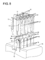
FIG. 8 is a perspective view of the device-side connector and the wire-side connector in the separated state showing the state where the wall on the front surface side of the accommodation case and the wall on the front surface side of the device-side connector are removed, -
FIG. 9 is a perspective view of an end device-side receptacle, -
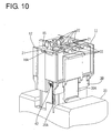
FIG. 10 is a perspective view of the connector during a connecting operation, and -
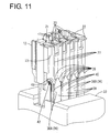
FIG. 11 is a perspective view of the connector during the connecting operation showing the state where the wall on the front surface side of the accommodation case and the wall on the front surface side of the device-side connector are removed. - One embodiment of the present invention is described with reference to
FIGS. 1 to 11 . As shown inFIG. 6 , aconnector 10 of this embodiment includes a wire-side connector 11 and a device-side connector 30 connectable to each other. The device-side connector 30 is a connector provided on a device-side where flat devices such as batteries and substrates are stacked. On the other hand, the wire-side connector 11 is a connector connected to ends of wires W such as a voltage detection line and a power line. Note that, in the following description, a connecting direction of the bothconnectors - As shown in
FIG. 3 , the wire-side connector 11 includes four (plural) terminal accommodatingportions 20, wire-side terminals 17 accommodated in the respectiveterminal accommodating portions 20 and anaccommodation case 12 for accommodating the plurality of terminal accommodatingportions 20. - The wire-
side terminal 17 includes awire connecting portion 17A to be connected to an end of the wire W and aterminal connecting portion 17B to be connected to a device-side terminal 37. Although not shown in detail, theterminal connecting portion 17B is in the form of a rectangular tube with open front and rear ends and a resilient contact piece is formed inside. The device-side terminal 37 is insertable into an opening on the front end of theterminal connecting portion 17B and the resilient contact piece is deflected and deformed to resiliently come into contact with the device-side terminal 37, whereby the bothterminals - A front side of the
accommodation case 12 is open as shown inFIG. 7 , and holdingrecesses portions 20 side by side are provided on edge parts of aback wall 15 of theaccommodation case 12 as shown inFIG. 1 . - A
first holding recess 16A formed on a left edge part ofFIG. 1 is shaped to be able to receive aholding piece 21 of theterminal accommodating portion 20 arranged on a left side inFIG. 1 . -
Second holding recesses 16B formed on a pair of side edge parts extending along an arrangement direction of the terminal accommodating portions 20 (lateral direction ofFIG. 1 ) out of the edge parts of theback wall 15 of theaccommodation case 12 are shaped to be able to receive holdingarms 22 of the terminal accommodatingportions 20. - As shown in
FIGS. 3 and4 , a receivingportion 13 for receiving a guidingprotrusion 42 of a device-side receptacle 36A on one end part to be described later is provided inside theaccommodation case 12. Note that, inFIGS. 5 ,8 and11 , a state where a wall on a front surface side of theaccommodation case 12 and a wall covering a front surface side of a device-side receptacle group 35 (wall on a front surface side of the device-side connector 30) out of a device-side coveringportion 33A are removed is shown to make conditions of the terminal accommodatingportions 20 and the device-side receptacles 36 comprehensive. Note that, in this embodiment, the device-side receptacle 36A on one end part and the other device-side receptacles 36B are referred to as an "end device-side receptacle 36A" and "other device-side receptacles 36B" when they are distinguished. - As shown in
FIG. 7 , the plurality of terminalaccommodating portions 20 are held in theaccommodation case 12 in a state movable in a direction (stacking direction in this embodiment) intersecting with a connecting direction (vertical direction ofFIG. 7 ). Clearances C are provided between adjacent terminalaccommodating portions 20 and between the terminalaccommodating portions 20 and theaccommodation case 12 as shown inFIG. 7 , whereby eachterminal accommodating portion 20 is movable in the direction intersecting with the connecting direction. The terminalaccommodating portions 20 move in the direction intersecting with the connecting direction, whereby a stacking tolerance in the device-side connector 30 is absorbed. - Each
terminal accommodating portion 20 is formed to project forward from theback wall 15. As shown inFIG. 3 , the wire-side terminal 17 can be accommodated into theterminal accommodating portion 20. When the wire-side terminal 17 is inserted into theterminal accommodating portion 20, a locking lance (not shown) provided in theterminal accommodating portion 20 is fitted into a lance hole (not shown) provided on the wire-side terminal 17 to retain the wire-side terminal 17. - The holding
piece 21 projecting outwardly is formed on a left edge of a rear end part of each terminal accommodatingportion 20 inFIG. 6 . A holdingpiece receiving portion 23 capable of receiving the holdingpiece 21 of the adjacentterminal accommodating portion 20 is formed on a right edge of the rear end part of each terminal accommodatingportion 20 inFIG. 6 , and a pair of holdingarms 22 to be received into the holding recesses 16B are formed to project in a direction substantially perpendicular to the arrangement direction of the terminalaccommodating portions 20 from opposite sides of the holdingpiece receiving portion 23. - A tapered
inclined surface 26 is formed on a front end part of theterminal accommodating portion 20 as shown inFIG. 8 and theterminal accommodating portion 20 is smoothly insertable into the device-side receptacle 36 during connection to the device-side connector 30. - A guide protrusion 27 (example of a guided portion) protruding outwardly in a width direction is provided on a side wall 20A arranged on a front side shown in
FIG 8 out of wall portions constituting theterminal accommodating portion 20. Although described in detail later, theterminal accommodating portion 20 is guided to take a proper connection posture by the contact of theguide protrusion 27 with aninclined surface 43 of the guidingprotrusion 42 of the end device-side receptacle 36B or an inclined surface 39 (example of a guiding portion) of the other device-side receptacle 36B and theterminal accommodating portion 20 is fitted and guided by the insertion of theguide protrusion 27 into a guide groove 40 (example of the guiding portion) of the device-side receptacle 36. - The plurality of terminal
accommodating portions 20 are successively accommodated into theaccommodation case 12 from a left side ofFIG. 8 . First, theterminal accommodating portion 20 arranged on the left end is inserted downwardly from above inFIG. 8 in a state where the holdingpiece 21 thereof is positioned to correspond to thefirst holding recess 16A of theaccommodation case 12 and the holdingarms 22 are positioned to correspond to the second holding recesses 16B. - Subsequently, the second
terminal accommodating portion 20 and the thirdterminal accommodating portion 20 from left are successively inserted. The secondterminal accommodating portion 20 and the thirdterminal accommodating portion 20 from left are inserted downwardly from above inFIG. 8 in a state where the holdingpieces 21 thereof are positioned to correspond to the holdingpiece receiving portions 23 of the adjacentterminal accommodating portions 20 and the holdingarms 22 are positioned to correspond to the second holding recesses 16B. - Finally, when the
terminal accommodating portion 20 on the right end is inserted downwardly from above inFIG. 8 in a state where the holdingpiece 21 thereof is positioned to correspond to the holdingpiece receiving portion 23 of the adjacentterminal accommodating portion 20 and the holdingarms 22 are positioned to correspond to the second holding recesses 16B, an accommodating operation of the terminalaccommodating portions 20 is completed. - The device-
side connector 30 is composed of a plurality of split connectors 32 provided for each device. The plurality of split connectors 32 are collectively covered in a stacked state by a device-side case 33. A part of the device-side case 33 covering the device-side receptacle group 35 serves as the device-side covering portion 33A. - Each split connector 32 includes the device-
side receptacle 36 and the device-side terminal 37 (seeFIG. 3 ). In this embodiment, a plurality of stacked device-side receptacles 36 of the split connectors 32 are referred to as the device-side receptacle group 35. The device-side terminal 37 is provided to project forward from a back wall of the device-side receptacle 36. - Two
inclined surfaces 39 are respectively formed on a shown upper end of awall 38 arranged on a front surface side of each of four (plural) device-side receptacles 36 to have a tapered upper end side (front end side in the connecting direction) as shown inFIG. 8 . Further, thewall 38 arranged on the front surface side of each device-side receptacle 36 is formed with a slit-like guide groove 40 connected to oneinclined surface 39 and extending in the connecting direction. Theguide protrusion 27 of theterminal accommodating portion 20 is fitted into theguide groove 40 to fit and guide theterminal accommodating portion 20 into the device-side receptacle 36. - As shown in
FIGS. 5 and9 , the guidingprotrusion 42 is provided on the end device-side receptacle 36A arranged on the left end part shown inFIG. 5 . As shown inFIG. 3 , the guidingprotrusion 42 is formed to project in the stacking direction (lateral direction as shown) in anopening 36C of the end device-side receptacle 36A and has a function of guiding the corresponding terminal accommodating portion 20 (terminal accommodating portion 20 on the left end inFIG. 5 ) in the proper connection posture into the end device-side receptacle 36A. Although the guidingprotrusion 42 projects in the stacking direction as shown inFIG. 3 , it is accommodated into the receivingportion 13 of theaccommodation case 12. - The guiding
protrusion 42 is formed with theinclined surface 43 inclined in a direction to enlarge theopening 36C toward the upper end of theopening 36C as shown inFIG. 3 . Theterminal accommodating portion 20 arranged on the end part is corrected into the proper connection posture by making a sliding movement after theguide protrusion 27 of thisterminal accommodating portion 20 comes into contact with theinclined surface 43 of the guidingprotrusion 42. Since theguide groove 40 is provided to be connected to theinclined surface 43 of the guidingprotrusion 42 in this embodiment, theguide protrusion 27 of theterminal accommodating portion 20 corrected into the proper connection posture by theinclined surface 43 of the guidingprotrusion 42 is fitted into theguide groove 40 and theterminal accommodating portion 20 is fitted and guided into the end device-side receptacle 36A. - Next, how to assemble the
connector 10 of this embodiment is described. The wire-side connector 11 is prepared by accommodating the wire-side terminals 17 connected to the wires W into the terminalaccommodating portions 20 after the four terminalaccommodating portions 20 are successively accommodated into theaccommodation case 12 from the end. - Simultaneously or before or after the assembling of the wire-
side connector 11, the four split connectors 32 constituting the device-side connector 30 are stacked to prepare the device-side connector 30 in the stacked state. The device-side case 33 is mounted on the device-side connector 30 in the stacked state prepared in this way. - Subsequently, the device-
side connector 30 and the wire-side connector 11 are connected. If the terminalaccommodating portions 20 of the wire-side connector 11 are in the proper connection posture, the wire-side connector 11 and the device-side connector 30 can be smoothly connected without requiring positioning and the like. - Since the plurality of terminal
accommodating portions 20 are held in theaccommodation case 12 in the state movable in the direction (stacking direction) intersecting with the connecting direction in this embodiment, the terminalaccommodating portions 20 of the wire-side connector 11 may be, for example, postured to be inclined rightwardly inFIG. 7 . If the wire-side connector 11 and the device-side connector 30 are connected in such a case, theguide protrusion 27 of theterminal accommodating portion 20 arranged on the end part comes into contact with the guidingprotrusion 42 of the end device-side receptacle 36A and theguide protrusions 27 of the other terminalaccommodating portions 20 come into contact with end parts of theopenings 36C of the other device-side receptacles 36B (seeFIG. 11 ). - The
guide protrusion 27 of theterminal accommodating portion 20 brought into contact with the guidingprotrusion 42 of the end device-side receptacle 36A is guided by theinclined surface 43 of the guidingprotrusion 42, whereby theterminal accommodating portion 20 is corrected into the proper connection posture. Theguide protrusion 27 of each terminal accommodatingportion 20 brought into contact with the end part (shown upper end part) of theopening 36C of the other device-side receptacle 36B is guided by theinclined surface 39 formed on theopening 36C of the other device-side receptacle 36B, whereby eachterminal accommodating portion 20 is corrected into the proper connection posture. - When being fitted into the
guide groove 40 from theinclined surfaces guide protrusion 27 of each terminal accommodatingportion 20 smoothly moves along the guide groove 40 (along the connecting direction), whereby the wire-side connector 11 is guided to be connected. When the wire-side connector 11 and the device-side connector 30 are properly connected as shown inFIGS. 1 and5 , the wire-side terminals 17 and the device-side terminals 37 are in a state electrically connectable to each other. At this time, the guidingprotrusion 42 provided on the end device-side receptacle 36A is received into the receivingportion 13 of the accommodation case 12 (seeFIG. 3 ). - Next, functions and effects of this embodiment are described.
- In this embodiment, the opening 36c of the end device-
side receptacle 36A arranged on the one end part is provided with the guidingprotrusion 42 projecting in the stacking direction and configured to guide the correspondingterminal accommodating portion 20 in the proper connection posture into the end device-side receptacle 36A, whereas theaccommodation case 12 is provided with the receivingportion 13 configured to receive the guidingprotrusion 42. - Accordingly, in this embodiment, the corresponding
terminal accommodating portion 20 is guided into the end device-side receptacle 36A while being corrected into the proper connection posture by the guidingprotrusion 42 provided on theopening 36C of the end device-side receptacle 36A, for example, even if theterminal accommodating portion 20 is inclined in the stacking direction. - Particularly in this embodiment, since the guiding
protrusion 42 is provided only on one end device-side receptacle 36A, the device-side receptacles 36 are enlarged only by a projecting dimension of the guidingprotrusion 42 and the enlargement of the device-side receptacles 36 can be suppressed more than in the case of considering the inclination of the terminalaccommodating portions 20. As a result, according to this embodiment, operation efficiency in connecting the device-side connector 30 and the wire-side connector 11 can be improved more than before while the enlargement of the device-side receptacles - Further, in this embodiment, the end device-
side receptacle 36A is provided with theguide groove 40 configured to guide theterminal accommodating portion 20 guided by the guidingprotrusion 42 into the end device-side receptacle 36A, whereas the correspondingterminal accommodating portion 20 is provided with theguide protrusion 27 formed to project in an outward direction from the wall portion constituting theterminal accommodating portion 20 and to be guided by theguide groove 40 of the end device-side receptacle 36A. - Thus, according to this embodiment, the
guide protrusion 27 of theterminal accommodating portion 20 is guided into the device-side receptacle guide groove 40 of the end device-side receptacle 36A after theterminal accommodating portion 20 corresponding to the end device-side receptacle 36A is corrected into the proper connection posture by the guidingprotrusion 42 of the end device-side receptacle 36A, wherefore operation efficiency in connection can be reliably improved. - Further, in this embodiment, each device-
side receptacle 36 is provided with theinclined surfaces 39 and the guide groove 40 (guiding portion) for guiding theterminal accommodating portion 20 in the proper connection posture into the corresponding device-side receptacle 36, whereas eachterminal accommodating portion 20 is provided with theguide protrusion 27 to be guided by theinclined surfaces 39 and theguide groove 40 of the device-side receptacle 36. - Thus, according to this embodiment, not only the
terminal accommodating portion 20 corresponding to the end device-side receptacle 36A, but also the other terminalaccommodating portions 36B are guided into the device-side receptacles 36 while being corrected into the proper connection posture. Therefore, operation efficiency in connecting the device-side connector 30 and the wire-side connector 11 can be further improved. - The present invention is not limited to the above described and illustrated embodiment. For example, the following embodiments are also included in the technical scope of the present invention.
- (1) In the above embodiment, the end device-
side receptacle 36A is provided with theguide groove 40 for guiding theterminal accommodating portion 20 guided by the guidingprotrusion 42 into the end device-side receptacle 36A, whereas the correspondingterminal accommodating portion 20 is provided with theguide protrusion 27 projecting in the outward direction from the wall portion constituting theterminal accommodating portion 20 and to be guided by theguide groove 40 of the end device-side receptacle. 36A. However, there is no limitation to this. - The end device-side receptacle may be formed with no guide groove and the terminal accommodating portion may be formed with no guide protrusion.
- (3) In the above embodiment, the guiding portion (
inclined surfaces 39, guide groove 40) is provided on the device-side receptacle 36, whereas the guided portion (guide protrusion 27) is provided on the wall portion 20A constituting theterminal accommodating portion 20. However, the guiding portion may be provided on the terminal accommodating portion and the guided portion may be provided on the device-side receptacle. - (4) In the above embodiment, the guiding portion is composed of the two
inclined surfaces 39 formed to taper the front end side in the connecting direction in theopening 36C of each device-side receptacle 36 and theguide groove 40 connected to oneinclined surface 39 and configured to guide theterminal accommodating portion 20 into the device-side receptacle 36 by receiving theguide protrusion 27. However, the present invention is not limited to this. For example, the guiding portion may be composed only of one inclined surface. - (5) Although all the device-
side receptacles 36 are provided with the guiding portion and all the terminalaccommodating portions 20 are provided with the guided portion in the above embodiment, some of the device-side receptacles may be provided with the guiding portion and some corresponding terminal accommodating portions may be provided with the guided portion. - (6) Although the device-
side connector 30 formed by stacking four split connectors 32 is described in the above embodiment, the number of the split connectors may be two, three, five or more. -
- 11 ...
- wire-side connector
- 12 ...
- accommodation case
- 13 ...
- receiving portion
- 17 ...
- wire-side terminal
- 20 ...
- terminal accommodating portion
- 27 ...
- guide protrusion (guided portion)
- 30 ...
- device-side connector
- 32 ...
- split connector
- 35 ...
- device-side receptacle group
- 36 ...
- device-side receptacle
- 36A ...
- end device-side receptacle
- 36B ...
- device-side receptacle other than end device-side receptacle
- 36C ...
- opening
- 37 ...
- device-side terminal
- 39 ...
- inclined surface (guiding portion)
- 40 ...
- guide groove (guiding portion)
- 42 ...
- guiding protrusion
- 43 ...
- inclined surface
- C ...
- clearance
- W ...
- wire
Claims (3)
- A connector, comprising a device-side connector provided on a device side and a wire-side connector provided on a wire side and to be connected to the device-side connector, wherein:the device-side connector includes a device-side receptacle group formed by stacking a plurality of device-side receptacles having an opening on a front side in a connecting direction;the wire-side connector includes a plurality of wire-side terminals, a plurality of terminal accommodating portions configured to respectively accommodate the wire-side terminals and to be individually accommodated into the device-side receptacles when the device-side connector and the wire-side connector are connected, and an accommodation case configured to hold the plurality of terminal accommodating portions movably in a direction intersecting with the connecting direction; andthe opening of an end device-side receptacle arranged on one end part out of the plurality of device-side receptacles includes a guiding protrusion projecting in the stacking direction and configured to guide the corresponding terminal accommodating portion in a proper connection posture into the end device-side receptacle, whereas the accommodation case includes a receiving portion configured to receive the guiding protrusion.
- A connector according to claim 1, wherein the end device-side receptacle includes a guide groove configured to guide the terminal accommodating portion guided by the guiding protrusion into the device-side receptacle, whereas the corresponding terminal accommodating portion includes a guide protrusion formed to project in an outward direction from a wall portion constituting the terminal accommodating portion and to be guided by the guide groove of the end device-side receptacle.
- A connector according to claim 1 or 2, wherein each of the plurality of device-side receptacles includes a guiding portion configured to guide the terminal accommodating portion in a proper connection posture into the corresponding device-side receptacle, whereas each of the plurality of terminal accommodating portions includes a guided portion to be guided by the guiding portion of the device-side receptacle.
Applications Claiming Priority (2)
| Application Number | Priority Date | Filing Date | Title |
|---|---|---|---|
| JP2013079435A JP5861658B2 (en) | 2013-04-05 | 2013-04-05 | connector |
| PCT/JP2014/057672 WO2014162884A1 (en) | 2013-04-05 | 2014-03-20 | Connector |
Publications (2)
| Publication Number | Publication Date |
|---|---|
| EP2983251A1 true EP2983251A1 (en) | 2016-02-10 |
| EP2983251A4 EP2983251A4 (en) | 2016-03-09 |
Family
ID=51658184
Family Applications (1)
| Application Number | Title | Priority Date | Filing Date |
|---|---|---|---|
| EP14778672.7A Withdrawn EP2983251A4 (en) | 2013-04-05 | 2014-03-20 | CONNECTOR |
Country Status (5)
| Country | Link |
|---|---|
| US (1) | US9640897B2 (en) |
| EP (1) | EP2983251A4 (en) |
| JP (1) | JP5861658B2 (en) |
| CN (1) | CN105103384B (en) |
| WO (1) | WO2014162884A1 (en) |
Families Citing this family (3)
| Publication number | Priority date | Publication date | Assignee | Title |
|---|---|---|---|---|
| JP2018137126A (en) * | 2017-02-22 | 2018-08-30 | トヨタ自動車株式会社 | Cell connector unit |
| JP7093699B2 (en) * | 2018-08-27 | 2022-06-30 | イリソ電子工業株式会社 | Electrical connector |
| JP7691726B2 (en) * | 2021-03-03 | 2025-06-12 | 日本圧着端子製造株式会社 | connector |
Family Cites Families (11)
| Publication number | Priority date | Publication date | Assignee | Title |
|---|---|---|---|---|
| JP2671729B2 (en) * | 1992-09-29 | 1997-10-29 | 住友電装株式会社 | Connector device |
| JP3281456B2 (en) | 1993-07-19 | 2002-05-13 | 富士重工業株式会社 | Car door |
| JPH0732877U (en) * | 1993-11-29 | 1995-06-16 | 古河電気工業株式会社 | Self-aligning connector |
| GB2293053B (en) | 1994-09-06 | 1998-10-21 | Sumitomo Wiring Systems | Divisional connector |
| JPH11176517A (en) * | 1997-12-15 | 1999-07-02 | Sumitomo Wiring Syst Ltd | Combined connector and joined structure of combined connector and casing |
| JP2002313488A (en) | 2001-04-17 | 2002-10-25 | Sumitomo Wiring Syst Ltd | Split connector |
| JP3949508B2 (en) * | 2002-05-20 | 2007-07-25 | 古河電気工業株式会社 | Connector mounting structure |
| JP4128899B2 (en) | 2003-04-24 | 2008-07-30 | 古河電気工業株式会社 | Joint connector |
| JP2007242251A (en) * | 2006-03-03 | 2007-09-20 | Jst Mfg Co Ltd | Electrical connector |
| JP4573845B2 (en) | 2007-02-09 | 2010-11-04 | 日本航空電子工業株式会社 | Connector and connector device |
| JP5673320B2 (en) | 2011-04-18 | 2015-02-18 | 株式会社オートネットワーク技術研究所 | connector |
-
2013
- 2013-04-05 JP JP2013079435A patent/JP5861658B2/en not_active Expired - Fee Related
-
2014
- 2014-03-20 US US14/781,073 patent/US9640897B2/en not_active Expired - Fee Related
- 2014-03-20 EP EP14778672.7A patent/EP2983251A4/en not_active Withdrawn
- 2014-03-20 WO PCT/JP2014/057672 patent/WO2014162884A1/en not_active Ceased
- 2014-03-20 CN CN201480020155.XA patent/CN105103384B/en not_active Expired - Fee Related
Also Published As
| Publication number | Publication date |
|---|---|
| JP2014203692A (en) | 2014-10-27 |
| WO2014162884A1 (en) | 2014-10-09 |
| CN105103384B (en) | 2017-10-31 |
| CN105103384A (en) | 2015-11-25 |
| US9640897B2 (en) | 2017-05-02 |
| EP2983251A4 (en) | 2016-03-09 |
| JP5861658B2 (en) | 2016-02-16 |
| US20160308298A1 (en) | 2016-10-20 |
Similar Documents
| Publication | Publication Date | Title |
|---|---|---|
| US9705229B2 (en) | Connector assembly | |
| EP2009747A1 (en) | Electrical connection system having wafer connectors | |
| EP2854239B1 (en) | High speed data module for high life cycle interconnect device | |
| EP2701241B1 (en) | Connector | |
| US9166343B1 (en) | Mezzanine receptacle connector | |
| JP2009004379A (en) | Electrical connection system | |
| JP2008078133A (en) | Electrical connection device | |
| US9413095B2 (en) | Connector | |
| US12230908B2 (en) | High density electrical connectors | |
| JP2015220184A (en) | connector | |
| JP2017521821A (en) | Electrical connector with terminal holder | |
| JP6352676B2 (en) | connector | |
| US9640897B2 (en) | Wire-side connector and device-side connector with mating guides | |
| US9419357B2 (en) | Connector assembly | |
| US7887368B1 (en) | Electrical connector having a dielectric insert for retaining an electrical contact | |
| CN105098434B (en) | Electrical connector | |
| US9698526B2 (en) | Connector with aligning plate | |
| KR101697256B1 (en) | Connector | |
| US10741964B2 (en) | Joint connector with short circuit members shorting selected tabs | |
| EP2983249B1 (en) | Device connector | |
| JP2014203691A (en) | Connector | |
| JP2017059491A (en) | connector | |
| CN202196930U (en) | Electric connector |
Legal Events
| Date | Code | Title | Description |
|---|---|---|---|
| PUAI | Public reference made under article 153(3) epc to a published international application that has entered the european phase |
Free format text: ORIGINAL CODE: 0009012 |
|
| 17P | Request for examination filed |
Effective date: 20151008 |
|
| AK | Designated contracting states |
Kind code of ref document: A1 Designated state(s): AL AT BE BG CH CY CZ DE DK EE ES FI FR GB GR HR HU IE IS IT LI LT LU LV MC MK MT NL NO PL PT RO RS SE SI SK SM TR |
|
| AX | Request for extension of the european patent |
Extension state: BA ME |
|
| A4 | Supplementary search report drawn up and despatched |
Effective date: 20160210 |
|
| RIC1 | Information provided on ipc code assigned before grant |
Ipc: H01R 13/631 20060101AFI20160202BHEP Ipc: H01R 13/514 20060101ALI20160202BHEP |
|
| DAX | Request for extension of the european patent (deleted) | ||
| STAA | Information on the status of an ep patent application or granted ep patent |
Free format text: STATUS: EXAMINATION IS IN PROGRESS |
|
| 17Q | First examination report despatched |
Effective date: 20170831 |
|
| GRAP | Despatch of communication of intention to grant a patent |
Free format text: ORIGINAL CODE: EPIDOSNIGR1 |
|
| STAA | Information on the status of an ep patent application or granted ep patent |
Free format text: STATUS: GRANT OF PATENT IS INTENDED |
|
| INTG | Intention to grant announced |
Effective date: 20180214 |
|
| STAA | Information on the status of an ep patent application or granted ep patent |
Free format text: STATUS: THE APPLICATION IS DEEMED TO BE WITHDRAWN |
|
| 18D | Application deemed to be withdrawn |
Effective date: 20180626 |