EP2983189A1 - Methods, apparatus and articles of manufacture to regulate relay coil switching - Google Patents
Methods, apparatus and articles of manufacture to regulate relay coil switching Download PDFInfo
- Publication number
- EP2983189A1 EP2983189A1 EP15179561.4A EP15179561A EP2983189A1 EP 2983189 A1 EP2983189 A1 EP 2983189A1 EP 15179561 A EP15179561 A EP 15179561A EP 2983189 A1 EP2983189 A1 EP 2983189A1
- Authority
- EP
- European Patent Office
- Prior art keywords
- relay
- time
- switching signal
- value
- pulse train
- Prior art date
- Legal status (The legal status is an assumption and is not a legal conclusion. Google has not performed a legal analysis and makes no representation as to the accuracy of the status listed.)
- Granted
Links
Images




Classifications
-
- H—ELECTRICITY
- H01—ELECTRIC ELEMENTS
- H01H—ELECTRIC SWITCHES; RELAYS; SELECTORS; EMERGENCY PROTECTIVE DEVICES
- H01H50/00—Details of electromagnetic relays
- H01H50/86—Means for introducing a predetermined time delay between the initiation of the switching operation and the opening or closing of the contacts
-
- H—ELECTRICITY
- H01—ELECTRIC ELEMENTS
- H01H—ELECTRIC SWITCHES; RELAYS; SELECTORS; EMERGENCY PROTECTIVE DEVICES
- H01H9/00—Details of switching devices, not covered by groups H01H1/00 - H01H7/00
- H01H9/54—Circuit arrangements not adapted to a particular application of the switching device and for which no provision exists elsewhere
- H01H9/56—Circuit arrangements not adapted to a particular application of the switching device and for which no provision exists elsewhere for ensuring operation of the switch at a predetermined point in the AC cycle
-
- H—ELECTRICITY
- H01—ELECTRIC ELEMENTS
- H01H—ELECTRIC SWITCHES; RELAYS; SELECTORS; EMERGENCY PROTECTIVE DEVICES
- H01H47/00—Circuit arrangements not adapted to a particular application of the relay and designed to obtain desired operating characteristics or to provide energising current
- H01H47/22—Circuit arrangements not adapted to a particular application of the relay and designed to obtain desired operating characteristics or to provide energising current for supplying energising current for relay coil
-
- H—ELECTRICITY
- H01—ELECTRIC ELEMENTS
- H01H—ELECTRIC SWITCHES; RELAYS; SELECTORS; EMERGENCY PROTECTIVE DEVICES
- H01H47/00—Circuit arrangements not adapted to a particular application of the relay and designed to obtain desired operating characteristics or to provide energising current
- H01H47/22—Circuit arrangements not adapted to a particular application of the relay and designed to obtain desired operating characteristics or to provide energising current for supplying energising current for relay coil
- H01H47/223—Circuit arrangements not adapted to a particular application of the relay and designed to obtain desired operating characteristics or to provide energising current for supplying energising current for relay coil adapted to be supplied by AC
-
- H—ELECTRICITY
- H01—ELECTRIC ELEMENTS
- H01H—ELECTRIC SWITCHES; RELAYS; SELECTORS; EMERGENCY PROTECTIVE DEVICES
- H01H7/00—Devices for introducing a predetermined time delay between the initiation of the switching operation and the opening or closing of the contacts
- H01H7/16—Devices for ensuring operation of the switch at a predetermined point in the AC cycle
-
- H—ELECTRICITY
- H01—ELECTRIC ELEMENTS
- H01H—ELECTRIC SWITCHES; RELAYS; SELECTORS; EMERGENCY PROTECTIVE DEVICES
- H01H2231/00—Applications
- H01H2231/012—Household appliance
Definitions
- This disclosure relates generally to relays, and, more particularly, to methods, apparatus, and articles of manufacture to regulate relay coil switching.
- Some traditional appliances such as ovens, stoves, ranges, and clothes dryers have relays that are operated to control the supply of power to high-current and/or high-voltage components, such as heating elements.
- Relay contact life may degrade when high-current loads are switched on and/or off when there is a large voltage potential across the contacts. The problem is worse when the current passing through the contacts is at or above the rated current handling of the relay.
- Example degradations include fused contacts, pitted contacts, carbon encrusted contacts, etc.
- Example prior art solutions include use of a zero-cross detection circuit to switch at zero-cross, and a walking pattern algorithm that attempts to perform switching randomly at different voltage potentials. The former solution does not always work correctly for 3-phase systems, and without feedback cannot verify or ensure that switching times are correct. Without means to verify switching time, performance degrades overtime. The latter solution only partially resolves the problem as switching still occurs occasionally under large voltage potential conditions. Moreover, the characteristics of relays change with time, temperature, usage, etc. It will be understood that relays do not close and open instantaneously due to, for example, mechanical effects, inertia and, may experience closure bounce due to spring effects.
- the methods, apparatus and articles of manufacture to regulate and/or control relay coil switching times disclosed herein perform an initial calibration, and then adaptively adjust over time relay coil switching times to maintain relay coil switching at or near a desired time relative to zero crossings of the power supply.
- An example desired time for initiating relay operate i.e., relay contact closure
- An example desired time for relay operate initiation is within +/- 1 milliseconds (ms) of zero-cross, assuming it takes approximately 1 ms to close the relay.
- An example desired time for initiating relay release i.e., relay open
- An example desired time is to initiate relay release is 1 to 2 ms before zero-cross.
- the methods, apparatus, and articles of manufacture to regulate and/or control relay coil switching disclosed herein may be used to control relay switching to occur at other times relative to zero-cross.
- An example relay calibration process uses an L1-N (line 1 minus neutral) zero-cross signal to time the relay coil switching signal, and reads the feedback signal from the relay contact output to measure how long it takes to close and open a relay.
- An example feedback signal is a pulse train formed by comparing L1-N to a threshold such that, for example, when the L1-N signal exceeds the threshold the pulse train is logic high or TRUE, and when the signal does not exceed the threshold the pulse train is logic low or FALSE.
- the threshold is typically non-zero due to transistor switching voltage, etc.
- the feedback signal is a pulse train due to the periodicity of L1-N (see FIG. 3 ).
- relay switching signals sent to each relay being controlled are adjusted so that the relay contacts are closed and opened in or near the middle of the feedback signal pulse, thereby allowing a reasonably accurate measurement of each relay's contact opening and closing durations.
- the initial relay calibration process is performed during manufacturing and/or on initial startup. The initial relay calibration process may be repeated or performed at other times, however, calibration relay switching when an appliance is not in operation may be perceived negatively by some persons.
- An example adaptive adjustment process uses the relay contact output feedback signal to make adjustments to the switching trigger times during normal operation.
- the process uses a modified line-straddling algorithm to adapt switching times so that relay contacts close near zero-cross +/- 1 ms, and open 1-2 ms before zero-cross. If the relay contact is closed or opened too early, the time at which the next corresponding relay switch signal is sent to the relay is moved forward in time with respect to zero-cross. If the relay contact is closed or opened too late, the time at which the next corresponding relay switch signal is sent to the relay is moved back in time with respect to zero-cross.
- the example methods, apparatus and articles of manufacture disclosed herein uses L1-N and L2-N (line 2 minus neutral) zero-cross signals to determine whether an AC power source is a split-single phase or three-phase source. When a three-phase power source is present and not accommodated for, switching will not occur at L1-L2 zero-cross. Thus, if a three-phase source is identified, the examples disclosed herein determine whether L1 leads or follows L2. The results are used to adjust relay switching times so that switching is done when the L1-L2 AC voltage across the relay contacts is at or near zero-cross.
- a disclosed example method of regulating switching times of a relay having a pair of contacts to selectively and electrically couple an analog alternating current (AC) power source and a load includes forming a digital pulse train representative of an AC signal at the load, determining a first value corresponding to a representative pulse width of the digital pulse train, providing a first relay switching signal to the relay at a first time relative to a zero crossing of the AC signal, selecting a second time for providing a second relay switching signal to the relay based the first value and a second value representative of the width of a first pulse of the digital pulse train associated with the first relay switching signal at the first time, and providing the second relay switching signal to the relay at the second time.
- AC alternating current
- FIG. 1 illustrates an example built-in electric range 10 having relay coil switching regulation and/or control in accordance with the teachings of this disclosure.
- the example range 10 described herein shares many features of a traditional range, which will not be described except as necessary for a complete understanding of this disclosure.
- the range 10 illustrated in FIG. 1 is a built-in range, that is, a range built into a countertop 12 and/or cabinets 14 of, for example, a kitchen or food preparation area, the range 10 may alternatively be embodied as a freestanding range.
- relay coil switching regulation and/or control methods, apparatus and articles of manufacture disclosed herein may be a part of and/or be used in association with any number and/or type(s) of other appliances such as, but not limited to, a gas range, a gas/electric range, a cooktop, a laundry dryer, a laundry washer, a dishwasher, a refrigerator, a freezer, a heat pump, an air conditioner, and a water heater, and/or any other device and/or apparatus in which relays are used to control electrical coupling between power supply and load.
- the example range 10 of FIG. 1 has a glass-ceramic cooktop 16 including one or more cooking areas 18. However, other types of cooktops may be used.
- a radiant heating element one of which is designated at reference numeral 19, is positioned below each of the cooking areas 18.
- the example range 10 includes an oven 20 having one or more racks 22 for positioning items in the oven 20, and one or more heating elements 24.
- the range 10 includes a door 26 moveably mounted to the range 10 that is selectively movable between opened and closed positions to close an opening of the oven 20, thereby providing selective access to the interior of the oven 20.
- the range 10 includes a control panel 28.
- the example control panel 28 includes respective knobs 30.
- other means of controlling the heating elements 19, such as capacitive touch areas, buttons, etc. may be used.
- the range 10 includes one or more control areas 32 and/or one or more display areas 34. Any number and/or type(s) of elements, devices and/or technologies may be used to implement the control area(s) 32 and the display area(s) 34.
- capacitive touch areas may be used to implement the control area(s) 32
- LCD liquid crystal display
- LED light emitting diode
- the range 10 includes a controller 36, which may be implemented by, for example, the example processor platform P100 of FIG. 19 .
- the controller 36 controls operation of the range 10 in response to user inputs received via the knobs 30 and/or the control area(s) 32.
- the controller 36 controls on and off states of the heating elements 19, 24 to maintain desired temperatures.
- Power is coupled to the heating elements 19, 24 via respective relays 212 and 214 (see FIG. 2 ).
- the controller 36 controls on and off states of the heating elements 19, 24 by regulating or controlling relay switching, that is, releasing (i.e., opening) and operating (i.e., closing) the relays 212, 214.
- the example controller 36 has a central processing unit (CPU) P105 and memory P115, P120 (see FIG. 19 ).
- the memory P115, P120 may be used to store control software that is executed by the CPU P105 in regulating and/or controlling relay switching.
- the controller 36 is operably coupled with one or more components P135, P140 of the range 10 for communicating with and controlling the operation of the components P135, P140 to complete a cycle of operation.
- Non-limiting examples of components P135, P140 that may be communicably coupled with the controller 36 include a relay 212, 214 (see FIG 2 ).
- the controller 36 may also be coupled with one or more sensors P135 provided in one or more of the systems of the range 10 to receive input from the sensors P135, which are known in the art and not shown for simplicity.
- sensors P135 that may be communicably coupled with the controller 36 include a temperature sensor, a sensor circuit 216, 218 (see FIG. 2 ), and a reference circuit 220, 222.
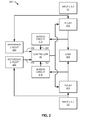
- FIG. 2 illustrates an example relay switching control system 200 that may be used to control and/or regulate relay switching for the example range 10 of FIG. 1 .
- the example relay switching control system 200 of FIG. 2 maintains relay coil switching at or near desired times relative to zero crossings of an AC power supply signal received via input lines L1 and L2.
- the lines L1 and L2 are selectively and electrically coupled to a load 224 via respective relays 212, 214.
- the example relay switching control system 200 includes the respective reference circuits 220, 222.
- the reference signals 226, 228 are pulse trains formed by comparing respective L1-N, L2-N signals to a threshold such that, for example, when the L1-N signal exceeds the threshold the pulse train 226 is logic high or TRUE, and when the L1-N signal does not exceed the threshold the pulse train 226 is logic low or FALSE.
- the pulse train 228 is similarly formed.
- the threshold is typically non-zero due to transistor switching voltage, etc.
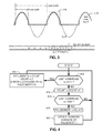
- An example L1-N signal and corresponding reference signal pulse train 226 are shown in the example graph of FIG. 3 .
- the reference signals 226, 228 are pulse trains due to the generally periodic nature of L1-N and L2-N (see FIG. 3 ).
- the example relay switching control system 200 includes the respective sensor circuits 216, 218.
- the sensor signals 230, 232 are pulse trains formed by comparing respective gated L1-N, L2-N signals to a threshold such that, for example, when the gated L1-N signal exceeds the threshold the pulse train 230 is a logic high or TRUE, and when the gated L1-N signal does not exceed the threshold the pulse train 230 is a logic low or FALSE.
- the sensor signal 232 is similarly formed.
- the threshold is typically non-zero due to transistor switching voltage, etc.
- An example L1-N signal and corresponding sensor signal pulse train 230 are shown in the example graph of FIG. 5 .
- the first pulse of the pulse train 230 is shortened because the relay 212 is closed during the positive going portion of the L1-N signal.
- the sensor signals 230, 232 are pulse trains due to the generally periodic nature of L1-N and L2-N signals (see FIG. 5 ).
- the pulse trains 230, 232 may have varying pulse widths due to varying relay switching times.
- the signals 226, 228, 230 and 232 are sampled at a rate of 4 kHz (kilocycles per second), however, other sample rates may be used.
- kHz quarterwave frequency
- the controller 36 determines a first value corresponding to a representative pulse width of the reference pulse train 226, and a second value corresponding to a representative cycle width of the reference pulse train 226.
- FIG. 4 is a flowchart illustrating an example method that may be performed and/or carried out by, for example, the processor 36, to determine the first and second values.
- the first value is computed as a moving or running average
- the second value is a counted value.
- additional and/or alternative methods of computing or determining the first and second values may be implemented.
- the method of FIG. 4 continues to be performed beyond initial calibration.
- the reference pulse train 226 is also used to detect or determine zero-cross times, which will be used in the methods described below to determine relay trigger times.
- the last four (4) samples of the reference signal 226 are used to detect rising and falling edges of the reference signal 226.
- last 4 samples of [0111] is indicative of a rising edge
- [1000] is indicative of a falling edge.
- the example method of FIG. 4 begins with the controller 36 comparing the last 4 samples to [0111] (block 410). If the last 4 samples are [0111] (block 410), the controller 36 saves COUNT as CYCLEWIDTH, resets COUNT to zero (0), and sets the value of ERROR to, for example, ((CYCLEWIDTH/2)-PULSEWIDTH)/2 (block 412). Control then returns to block 410.
- the controller 36 increments COUNT (block 414). If the last 4 samples are [1000] (block 416), the controller 36 saves COUNT as PULSEWIDTH (block 418), and updates a running or moving average of PULSEWIDTH (block 420). Control then returns to block 410.
- control returns to block 410.
- Initial calibration continues with a determination of operate and release times that result in a PULSEWIDTH of a pulse associated with a relay switch event that is approximately half the average PULSEWIDTH computed or determined by, for example, using the example method of FIG. 4 . Because the sensor signals 230, 232 are gated and thresholded, targeting half the average PULSEWIDTH allows greater visibility into relay operate or release times that occur early or late. Other targets may be used.
- FIG. 5 is a graph illustrating an example relay operate event that occurs approximately midway in the positive going portion of the L1-N signal. That is, in the example of FIG. 5 , relay operate is occurring at or near the desired time.
- FIG. 6 is a graph illustrating an example relay operate event that is early.
- FIG. 7 is a graph illustrating an example relay operate event that is late.
- FIG. 8 is a flowchart illustrating an example method that may be performed or carried out by, for example, the processor 36, to determine a desired relay operate trigger time.
- the method of FIG. 8 begins with processor 36 setting OPERATETIME to SAVEDTIME (block 810), where OPERATETIME is the estimated time it takes the relay 212 to close.
- the processor 36 sets TRIGGERTIME equal to ZEROCROSSTIME + AVGPULSEWIDTH/2 - OPERATETIME (block 812), where AVGPULSEWIDTH is determined using, for example, the method of FIG. 4 , and ZEROCROSSTIME is determined using the reference signal 226.
- the controller 36 When the TRIGGERTIME is reached (block 814), the controller 36 operates the relay 212 (i.e., sends a relay operate switching signal to the relay 212) (block 816), and measures the width of the first pulse following the relay switching signal (block 818). If the measured RELAYPULSEWIDTH is in range (block 820), control exits from the example method of FIG. 8 . In range may be determined by, for example, comparing RELAYPULSEWIDTH and 1 ⁇ 2 of AVGPULSEWIDTH using a threshold.
- the controller 36 updates OPERATETIME (block 822), and control returns to block 812 to trigger the relay 212 again.
- FIG. 9 is a graph illustrating an example relay release event that occur approximately midway in the positive going portion of the L1-N signal. That is, the example of FIG. 9 , relay release is occurring at or near the desired time.
- FIG. 10 is a graph illustrating an example relay release event that is early.
- FIG. 11 is a graph illustrating an example relay release event that is late.
- FIG. 12 is a flowchart illustrating an example method that may be performed or carried out by, for example, the processor 36, to determine a desired relay release trigger time.
- the method of FIG. 12 begins with processor 36 setting RELEASETIME to SAVEDTIME (block 1210), where RELEASETIME is the estimated time it takes the relay 212 to open.
- the processor 36 sets TRIGGERTIME to ZEROCROSSTIME + AVGPULSEWIDTH/2 - RELEASETIME (block 1212), where AVGPULSEWIDTH is determined using, for example, the method of FIG. 4 , and ZEROCROSSTIME is determined using the reference signal 226.
- the controller 36 releases the relay 212 (i.e., sends a relay release switching signal to the relay 212) (block 1216), and measures the width of the pulse preceding the relay switching signal (block 1218). If the RELAYPULSEWIDTH is in range (block 1220), control exits from the example method of FIG. 12 . In range may be determined by, for example, comparing RELAYPULSEWIDTH and 1 ⁇ 2 of AVGPULSEWIDTH using a threshold.
- the controller 36 updates the RELEASETIME (block 1222), and control returns to block 1212 to trigger the relay 212 again.
- an example adaptive adjustment process uses the relay contact output feedback signal 230 to make adjustments to relay switching trigger times during operation.
- the process uses a modified line-straddling algorithm to adapt relay operate trigger time so that relay contacts close near to zero-cross +/- 1 ms. If the relay contacts close too early as shown in FIG. 13 , the time at which the next corresponding relay operate trigger signal is sent to the relay 212 is moved forward in time with respect to zero-cross. Thus, the relay operate trigger time will progressively move forward in time until the relay closure straddles zero-cross.
- FIG. 14 is a flowchart illustrating an example method that may be performed or carried out by, for example, the processor 36, to adaptively adjust relay operate trigger time.
- the method of FIG. 14 begins with the processor 36 setting TRIGGERTIME (block 1410).
- TRIGGERTIME is reached (block 1412)
- the processor 36 operates the relay 212 (i.e., sends a relay operate switching signal to the relay) (block 1414), and measures the width of the first pulse following the relay operate switching signal (block 1416). If OPERATETIME results in a measured RELAYPULSEWIDTH corresponding to the closure occurring too far before the zero-cross (block 1418), where ERROR is determined using the example method of FIG.
- the processor 36 increments OPERATETIME by, for example, 2 ms (block 1420). If OPERATETIME results in a measured RELAYPULSEWIDTH corresponding to the closure straddling the zero-cross (block 1418), the processor 36 decrements OPERATETIME by, for example, 0.25 ms (block 1422). OPERATETIME is decremented at block 1422 to enable future closures to facilitate updates of OPERATETIME, as needed.
- the process uses a modified line-straddling algorithm to adapt relay release switching times so that relay contacts open 1-2 ms before zero-cross. If the relay contacts are opened too early, the time at which the next corresponding relay release switch signal is sent to the relay 212 is moved forward in time with respect to zero-cross. Thus, the relay release trigger time will progressively move forward in time until the relay 212 open occurs 1-2 ms before zero-cross.
- FIG. 16 is a flowchart illustrating an example method that may be performed and/or carried out by, for example, the processor 36, to adaptively adjust relay release trigger time.
- the method of FIG. 16 begins with the processor 36 setting TRIGGERTIME (block 1610).
- TRIGGERTIME is reached (block 1612)
- the processor 36 releases the relay (i.e., sends a relay release switching signal to the relay 212) (block 1614), and measures the width of the pulse preceding the relay switching signal (block 1616). If RELEASETIME results in a measured RELAYPULSEWIDTH corresponding to the release occurring too far ahead of zero-cross (block 1618), where ERROR is determined using the example method of FIG.
- the processor 36 increments RELEASETIME by, for example, 1 ms (block 1620). If RELEASETIME results in a measured RELAYPULSEWIDTH corresponding to the release being too close to zero-cross (block 1618), the processor 36 decrements RELEASETIME by, for example, 0.25 ms (block 1622).
- FIG. 17 is a graph illustrating relationships between different phases of a split-single phase and a three-phase power supply.
- zero crossings at the load (L1-L2) do not coincide with zero crossings of the L1-N and L2-N inputs, as shown in FIG. 17 .
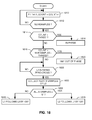
- FIG. 18 is a flowchart illustrating an example method that may be performed and/or carried out by, for example, the processor 36, to detect relationships between the L1 and L2 inputs.
- the example method of FIG. 18 begins with the processor 36 counting the number of times (COUNT) in NUMSAMPLES samples that reference signal 226 (L1-N) does not equal reference signal 228 (L2-N) (blocks 1810 and 1812). If COUNT is less than a threshold THRES1 (block 1814), then the processor 36 determines that L1 and L2 are in-phase (block 1816), and control exits from the example method of FIG. 18 .
- An example value of THRES1 is 6, when the sampling rate is 4 kHz, NUMSAMPLES is 200, and the frequency of the AC voltage supply is 60 Hz.
- COUNT is greater than another threshold THRES2 (block 1818)
- the processor 36 determines that L1 and L2 are 180° out-of-phase (block 1820), and control exits from the example method of FIG. 18 .
- An example value of THRES2 is 194, when the sampling rate is 4 kHz, NUMSAMPLES is 200, and the frequency of the AC voltage supply is 60 Hz.
- the processor 36 waits for the next rising zero-cross of L1-N (block 1825), and then collects the next five (5) samples of reference signal 228 (L2-N) (block 1830). If all 5 samples are zero (0) (block 1835), the processor 36 determines that L2 follows L1 by 120° (block 1840), and control exits from the example method of FIG. 18 . Otherwise, the processor 36 determines that L1 follows L2 by 120° (block 1840), and control exits from the example method of FIG. 18 .
- the processor 36 can determine zero-crossings of the L1-L2 voltage at the load 224 based on zero-crossings of L1-N.
- zero-cross of L1-L2 corresponds to zero-cross of L1-N.
- zero-cross of L1-L2 precedes L1-N zero-cross by 90°.
- L2 follows L1 by 120°, then zero-cross of L1-L2 precedes L1-N zero-cross by 30°, and when L1 follows L2 by 120°, then zero-cross of L1-L2 lags behind L1-N zero-cross by 30°.
- the processor 36 can maintain relay switching times based on the reference signal 226 (L1-N) and corresponding sensor signal 230, and adjust OPERATETIME and RELEASTTIME to accommodate the phase relationship.
- the example methods shown in FIGS. 4 , 8 , 12 , 14 , 16 and 18 may, for example, be implemented as machine-readable instructions carried out by one or more processors to implement the example controller 36 of FIGS. 1 and 2 .
- a processor, a controller and/or any other suitable processing device may be used, configured and/or programmed to execute and/or carry out the example methods of FIGS. 4 , 8 , 12 , 14 , 16 and 18 .
- FIGS. 4 , 8 , 12 , 14 , 16 and 18 may, for example, be implemented as machine-readable instructions carried out by one or more processors to implement the example controller 36 of FIGS. 1 and 2 .
- a processor, a controller and/or any other suitable processing device may be used, configured and/or programmed to execute and/or carry out the example methods of FIGS. 4 , 8 , 12 , 14 , 16 and 18 .
- Machine-readable instructions comprise, for example, instructions that cause a processor, a computer and/or a machine having a processor to perform one or more particular processes. Alternatively, some or all of the example methods of FIGS.
- FIGS. 4 , 8 , 12 , 14 , 16 and 18 may be implemented using any combination(s) of fuses, application-specific integrated circuit(s) (ASIC(s)), programmable logic device(s) (PLD(s)), field-programmable logic device(s) (FPLD(s)), field programmable gate array(s) (FPGA(s)), discrete logic, hardware, firmware, etc. Also, some or all of the example methods of FIGS. 4 , 8 , 12 , 14 , 16 and 18 may be implemented using any combination of any of the foregoing techniques, for example, any combination of firmware, software, discrete logic and/or hardware. Further, many other methods of implementing the example methods of FIGS.
- FIGS. 4 , 8 , 12 , 14 , 16 and 18 may be employed.
- the order of execution may be changed, and/or one or more of the blocks and/or interactions described may be changed, eliminated, sub-divided, or combined.
- any or the entire example methods of FIGS. 4 , 8 , 12 , 14 , 16 and 18 may be carried out sequentially and/or carried out in parallel by, for example, separate processing threads, processors, devices, discrete logic, circuits, etc.
- the term "computer-readable medium” is expressly defined to include any type of computer-readable medium and to expressly exclude propagating signals.
- Example computer-readable medium include, but are not limited to, a volatile and/or non-volatile memory, a volatile and/or non-volatile memory device, a compact disc (CD), a digital versatile disc (DVD), a read-only memory (ROM), a random-access memory (RAM), a programmable ROM (PROM), an electronically-programmable ROM (EPROM), an electronically-erasable PROM (EEPROM), an optical storage disk, an optical storage device, a magnetic storage disk, a magnetic storage device, a cache, and/or any other storage media in which information is stored for any duration (e.g., for extended time periods, permanently, brief instances, for temporarily buffering, and/or for caching of the information) and that can be accessed by a processor, a computer and/or other machine having a processor, such as the example processor platform P100 discussed below in connection with FIG. 19
- FIG. 19 illustrates an example processor platform P100 capable of executing, performing and/or otherwise carrying out the example methods of FIGS. 4 , 8 , 12 , 14 , 16 and 18 to implement the example controller 36 of FIGS. 1 and 2 .
- the example processor platform P100 can be, for example, any type of computing device containing a processor.
- the processor platform P100 of the instant example includes at least one programmable processor P105.
- the processor P105 can be implemented by one or more Atmel®, Intel®, AMD®, and/or ARM® microprocessors. Of course, other processors from other processor families and/or manufacturers are also appropriate.
- the processor P105 executes coded instructions P110 present in main memory of the processor P105 (e.g., within a volatile memory P115 and/or a non-volatile memory P120), stored on a storage device P150, stored on a removable computer-readable storage medium P155 such as a CD, a DVD and/or a FLASH drive.
- the processor P105 may execute, among other things, the example methods of FIGS. 4 , 8 , 12 , 14 , 16 and 18 .
- the coded instructions P110 may include instructions corresponding to the example methods of FIGS. 4 , 8 , 12 , 14 , 16 and 18 .
- the processor P105 is in communication with the main memory including the non-volatile memory P120 and the volatile memory P115, and the storage device P150 via a bus P125.
- the volatile memory P115 may be implemented by, for example, synchronous dynamic random access memory (SDRAM), dynamic random access memory (DRAM), RAMBUS® dynamic random access memory (RDRAM) and/or any other type of RAM device(s).
- the non-volatile memory P120 may be implemented by, for example, flash memory(-ies), flash memory device(s) and/or any other desired type of memory device(s). Access to the memory P115 and P120 may be controlled by a memory controller.
- the processor platform P100 also includes an interface circuit P130.
- Any type of interface standard such as an external memory interface, serial port, general-purpose input/output, as an Ethernet interface, a universal serial bus (USB), and/or a peripheral component interface (PCI) express interface, etc, may implement the interface circuit P130.
- interface standard such as an external memory interface, serial port, general-purpose input/output, as an Ethernet interface, a universal serial bus (USB), and/or a peripheral component interface (PCI) express interface, etc, may implement the interface circuit P130.
- One or more input devices P135 are connected to the interface circuit P130.
- the input device(s) P135 permit a user to enter data and commands into the processor P105.
- the input device(s) P135 can be implemented by, for example, the knobs 30, the control area(s) 32, a keyboard, a mouse, a touchscreen, a track-pad, a trackball, an isopoint and/or a voice recognition system.
- the input device(s) P135 may also implement the reference circuits 220, 222 and/or the sensor circuits 216, 218,
- One or more output devices P140 are also connected to the interface circuit P130.
- the output devices P140 can be implemented, for example, by display devices (e.g., a display, indicators, light emitting diodes, and/or speakers) to implement, for example, the display area(s) 34.
- the output devices P140 may also include the relays 212, 214.
- the interface circuit P130 may also includes one or more communication device(s) P145 such as a network interface card to facilitate exchange of data with other appliances, devices, computers, nodes and/or routers of a network.
- communication device(s) P145 such as a network interface card to facilitate exchange of data with other appliances, devices, computers, nodes and/or routers of a network.
Landscapes
- Engineering & Computer Science (AREA)
- Power Engineering (AREA)
- Physics & Mathematics (AREA)
- Electromagnetism (AREA)
- Electronic Switches (AREA)
Abstract
Description
- This disclosure relates generally to relays, and, more particularly, to methods, apparatus, and articles of manufacture to regulate relay coil switching.
- Some traditional appliances, such as ovens, stoves, ranges, and clothes dryers have relays that are operated to control the supply of power to high-current and/or high-voltage components, such as heating elements.
- Relay contact life may degrade when high-current loads are switched on and/or off when there is a large voltage potential across the contacts. The problem is worse when the current passing through the contacts is at or above the rated current handling of the relay. Example degradations include fused contacts, pitted contacts, carbon encrusted contacts, etc. Example prior art solutions include use of a zero-cross detection circuit to switch at zero-cross, and a walking pattern algorithm that attempts to perform switching randomly at different voltage potentials. The former solution does not always work correctly for 3-phase systems, and without feedback cannot verify or ensure that switching times are correct. Without means to verify switching time, performance degrades overtime. The latter solution only partially resolves the problem as switching still occurs occasionally under large voltage potential conditions. Moreover, the characteristics of relays change with time, temperature, usage, etc. It will be understood that relays do not close and open instantaneously due to, for example, mechanical effects, inertia and, may experience closure bounce due to spring effects.
- To overcome at least these problems, the methods, apparatus and articles of manufacture to regulate and/or control relay coil switching times disclosed herein perform an initial calibration, and then adaptively adjust over time relay coil switching times to maintain relay coil switching at or near a desired time relative to zero crossings of the power supply. An example desired time for initiating relay operate (i.e., relay contact closure) is to straddle zero-cross with the relay operate. An example desired time for relay operate initiation is within +/- 1 milliseconds (ms) of zero-cross, assuming it takes approximately 1 ms to close the relay. An example desired time for initiating relay release (i.e., relay open) is to initiate opening the relay before zero-cross to avoid flash effects due to increasing voltage as the contacts open. An example desired time is to initiate relay release is 1 to 2 ms before zero-cross. Of course, the methods, apparatus, and articles of manufacture to regulate and/or control relay coil switching disclosed herein may be used to control relay switching to occur at other times relative to zero-cross.
- An example relay calibration process uses an L1-N (
line 1 minus neutral) zero-cross signal to time the relay coil switching signal, and reads the feedback signal from the relay contact output to measure how long it takes to close and open a relay. An example feedback signal is a pulse train formed by comparing L1-N to a threshold such that, for example, when the L1-N signal exceeds the threshold the pulse train is logic high or TRUE, and when the signal does not exceed the threshold the pulse train is logic low or FALSE. The threshold is typically non-zero due to transistor switching voltage, etc. The feedback signal is a pulse train due to the periodicity of L1-N (seeFIG. 3 ). During calibration, relay switching signals sent to each relay being controlled are adjusted so that the relay contacts are closed and opened in or near the middle of the feedback signal pulse, thereby allowing a reasonably accurate measurement of each relay's contact opening and closing durations. In some examples, the initial relay calibration process is performed during manufacturing and/or on initial startup. The initial relay calibration process may be repeated or performed at other times, however, calibration relay switching when an appliance is not in operation may be perceived negatively by some persons. - An example adaptive adjustment process uses the relay contact output feedback signal to make adjustments to the switching trigger times during normal operation. In an example, the process uses a modified line-straddling algorithm to adapt switching times so that relay contacts close near zero-cross +/- 1 ms, and open 1-2 ms before zero-cross. If the relay contact is closed or opened too early, the time at which the next corresponding relay switch signal is sent to the relay is moved forward in time with respect to zero-cross. If the relay contact is closed or opened too late, the time at which the next corresponding relay switch signal is sent to the relay is moved back in time with respect to zero-cross.
- In some examples, the example methods, apparatus and articles of manufacture disclosed herein uses L1-N and L2-N (
line 2 minus neutral) zero-cross signals to determine whether an AC power source is a split-single phase or three-phase source. When a three-phase power source is present and not accommodated for, switching will not occur at L1-L2 zero-cross. Thus, if a three-phase source is identified, the examples disclosed herein determine whether L1 leads or follows L2. The results are used to adjust relay switching times so that switching is done when the L1-L2 AC voltage across the relay contacts is at or near zero-cross. - A disclosed example method of regulating switching times of a relay having a pair of contacts to selectively and electrically couple an analog alternating current (AC) power source and a load includes forming a digital pulse train representative of an AC signal at the load, determining a first value corresponding to a representative pulse width of the digital pulse train, providing a first relay switching signal to the relay at a first time relative to a zero crossing of the AC signal, selecting a second time for providing a second relay switching signal to the relay based the first value and a second value representative of the width of a first pulse of the digital pulse train associated with the first relay switching signal at the first time, and providing the second relay switching signal to the relay at the second time.
-
-
FIG. 1 is a schematic view of an example appliance in the form of a built-in electric range including relay coil switching regulation and control in accordance with the teachings of this disclosure. -
FIG. 2 is a schematic of a disclosed example relay control system for an appliance such as the example range ofFIG. 1 . -
FIG. 3 is a graph depicting an example AC signal and corresponding pulse train. -
FIG. 4 is a flowchart illustrating an example method that may be performed to estimate an average cycle width and pulse width for the example pulse train ofFIG. 3 . -
FIGS. 5-7 are graphs depicting example pulse widths corresponding to different relay operate times. -
FIG. 8 is a flowchart illustrating an example method that may be performed to determine a desired relay operate time. -
FIGS. 9-11 are graphs depicting example pulse widths corresponding to different relay release times. -
FIG. 12 is a flowchart illustrating an example method that may be performed to determine a desired relay release time. -
FIG. 13 is a graph depicting example updates of relay operate times during operation. -
FIG. 14 is a flowchart illustrating an example method that may be performed to update relay operate time during operation. -
FIG. 15 is a graph depicting example updates of relay release times during operation. -
FIG. 16 is a flowchart illustrating an example method that may be performed to update relay release time during operation. -
FIG. 17 is a graph depicting example relationships between leads of a split-phase or a three-phase AC power source. -
FIG. 18 is a flowchart illustrating an example method of determining phase relationships between input lines. -
FIG. 19 is a schematic illustration of an example processor platform that may be used and/or programmed to implement the example relay control system ofFIG. 2 and/or to execute the example methods disclosed herein. - In this specification and the appended claims, the singular forms "a," "an" and "the" do not exclude the plural referent unless the context clearly dictates otherwise. Further, conjunctions such as "and," "or," and "and/or" are inclusive unless the context clearly dictates otherwise. For example, "A and/or B" includes A alone, B alone, and A with B. Further still, connecting lines, or connectors shown in the various figures presented are intended to represent exemplary functional relationships and/or physical or logical couplings between the various elements. It should be noted that many alternative or additional functional relationships, physical connections or logical connections may be present in a practical device. Additionally, no item or component is essential to the practice of the embodiments disclosed herein unless the element is specifically described as "essential" or "critical". Moreover, terms such as, but not limited to, approximately, substantially, etc. are used herein to indicate that a precise value is not required, need not be specified, etc. For example, a first value being approximately a second value means that from a practical implementation perspective they can be considered as if equal. As used herein, such terms will have ready and instant meaning to one of ordinary skill in the art.
-
FIG. 1 illustrates an example built-in electric range 10 having relay coil switching regulation and/or control in accordance with the teachings of this disclosure. The example range 10 described herein shares many features of a traditional range, which will not be described except as necessary for a complete understanding of this disclosure. Although the range 10 illustrated inFIG. 1 is a built-in range, that is, a range built into acountertop 12 and/orcabinets 14 of, for example, a kitchen or food preparation area, the range 10 may alternatively be embodied as a freestanding range. Moreover, while the examples disclosed herein are described with reference the range 10, it should be understood that the example relay coil switching regulation and/or control methods, apparatus and articles of manufacture disclosed herein may be a part of and/or be used in association with any number and/or type(s) of other appliances such as, but not limited to, a gas range, a gas/electric range, a cooktop, a laundry dryer, a laundry washer, a dishwasher, a refrigerator, a freezer, a heat pump, an air conditioner, and a water heater, and/or any other device and/or apparatus in which relays are used to control electrical coupling between power supply and load. - The example range 10 of
FIG. 1 has a glass-ceramic cooktop 16 including one ormore cooking areas 18. However, other types of cooktops may be used. A radiant heating element, one of which is designated atreference numeral 19, is positioned below each of thecooking areas 18. The example range 10 includes anoven 20 having one ormore racks 22 for positioning items in theoven 20, and one ormore heating elements 24. The range 10 includes adoor 26 moveably mounted to the range 10 that is selectively movable between opened and closed positions to close an opening of theoven 20, thereby providing selective access to the interior of theoven 20. - To enable a user to control operation of the range 10, the range 10 includes a
control panel 28. To control operation of theheating elements 19, theexample control panel 28 includesrespective knobs 30. However, other means of controlling theheating elements 19, such as capacitive touch areas, buttons, etc. may be used. To control other operations of the range 10 such as, but not limited to, oven temperature, timer, cook time, time of day, etc., the range 10 includes one ormore control areas 32 and/or one ormore display areas 34. Any number and/or type(s) of elements, devices and/or technologies may be used to implement the control area(s) 32 and the display area(s) 34. For example, capacitive touch areas may be used to implement the control area(s) 32, and liquid crystal display (LCD) or light emitting diode (LED) display technologies may be used to implement the display area(s) 34. - To control operation of the range 10, the range 10 includes a
controller 36, which may be implemented by, for example, the example processor platform P100 ofFIG. 19 . Thecontroller 36 controls operation of the range 10 in response to user inputs received via theknobs 30 and/or the control area(s) 32. For example, thecontroller 36 controls on and off states of theheating elements heating elements respective relays 212 and 214 (seeFIG. 2 ). Thecontroller 36 controls on and off states of theheating elements relays - The
example controller 36 has a central processing unit (CPU) P105 and memory P115, P120 (seeFIG. 19 ). The memory P115, P120 may be used to store control software that is executed by the CPU P105 in regulating and/or controlling relay switching. Thecontroller 36 is operably coupled with one or more components P135, P140 of the range 10 for communicating with and controlling the operation of the components P135, P140 to complete a cycle of operation. Non-limiting examples of components P135, P140 that may be communicably coupled with thecontroller 36 include arelay 212, 214 (seeFIG 2 ). Thecontroller 36 may also be coupled with one or more sensors P135 provided in one or more of the systems of the range 10 to receive input from the sensors P135, which are known in the art and not shown for simplicity. Non-limiting examples of sensors P135 that may be communicably coupled with thecontroller 36 include a temperature sensor, asensor circuit 216, 218 (seeFIG. 2 ), and areference circuit -
FIG. 2 illustrates an example relay switchingcontrol system 200 that may be used to control and/or regulate relay switching for the example range 10 ofFIG. 1 . The example relay switchingcontrol system 200 ofFIG. 2 maintains relay coil switching at or near desired times relative to zero crossings of an AC power supply signal received via input lines L1 and L2. The lines L1 and L2 are selectively and electrically coupled to aload 224 viarespective relays - To provide
reference signals control system 200 includes therespective reference circuits pulse train 226 is logic high or TRUE, and when the L1-N signal does not exceed the threshold thepulse train 226 is logic low or FALSE. Thepulse train 228 is similarly formed. The threshold is typically non-zero due to transistor switching voltage, etc. An example L1-N signal and corresponding referencesignal pulse train 226 are shown in the example graph ofFIG. 3 . The reference signals 226, 228 are pulse trains due to the generally periodic nature of L1-N and L2-N (seeFIG. 3 ). - To provide
sensor signals relays control system 200 includes therespective sensor circuits pulse train 230 is a logic high or TRUE, and when the gated L1-N signal does not exceed the threshold thepulse train 230 is a logic low or FALSE. Thesensor signal 232 is similarly formed. The threshold is typically non-zero due to transistor switching voltage, etc. An example L1-N signal and corresponding sensorsignal pulse train 230 are shown in the example graph ofFIG. 5 . InFIG. 5 , the first pulse of thepulse train 230 is shortened because therelay 212 is closed during the positive going portion of the L1-N signal. The sensor signals 230, 232 are pulse trains due to the generally periodic nature of L1-N and L2-N signals (seeFIG. 5 ). However, as shown inFIG. 5 , the pulse trains 230, 232 may have varying pulse widths due to varying relay switching times. - In some examples, the
signals - As part of an initial calibration, the
controller 36 determines a first value corresponding to a representative pulse width of thereference pulse train 226, and a second value corresponding to a representative cycle width of thereference pulse train 226.FIG. 4 is a flowchart illustrating an example method that may be performed and/or carried out by, for example, theprocessor 36, to determine the first and second values. In the example ofFIG. 4 , the first value is computed as a moving or running average, and the second value is a counted value. However, additional and/or alternative methods of computing or determining the first and second values may be implemented. In some examples, the method ofFIG. 4 continues to be performed beyond initial calibration. In the examples disclosed herein, thereference pulse train 226 is also used to detect or determine zero-cross times, which will be used in the methods described below to determine relay trigger times. - In the example of
FIGS. 3 and 4 , the last four (4) samples of thereference signal 226 are used to detect rising and falling edges of thereference signal 226. In particular, last 4 samples of [0111] is indicative of a rising edge, and [1000] is indicative of a falling edge. - The example method of
FIG. 4 begins with thecontroller 36 comparing the last 4 samples to [0111] (block 410). If the last 4 samples are [0111] (block 410), thecontroller 36 saves COUNT as CYCLEWIDTH, resets COUNT to zero (0), and sets the value of ERROR to, for example, ((CYCLEWIDTH/2)-PULSEWIDTH)/2 (block 412). Control then returns to block 410. - Returning to block 410, if the last 4 samples are not [0111] (block 410), the
controller 36 increments COUNT (block 414). If the last 4 samples are [1000] (block 416), thecontroller 36 saves COUNT as PULSEWIDTH (block 418), and updates a running or moving average of PULSEWIDTH (block 420). Control then returns to block 410. - Returning to block 416, if the last 4 samples are not [1000] (block 416), control returns to block 410.
- Initial calibration continues with a determination of operate and release times that result in a PULSEWIDTH of a pulse associated with a relay switch event that is approximately half the average PULSEWIDTH computed or determined by, for example, using the example method of
FIG. 4 . Because the sensor signals 230, 232 are gated and thresholded, targeting half the average PULSEWIDTH allows greater visibility into relay operate or release times that occur early or late. Other targets may be used. - Turning first to relay operate trigger time,
FIG. 5 is a graph illustrating an example relay operate event that occurs approximately midway in the positive going portion of the L1-N signal. That is, in the example ofFIG. 5 , relay operate is occurring at or near the desired time.FIG. 6 is a graph illustrating an example relay operate event that is early.FIG. 7 is a graph illustrating an example relay operate event that is late. -
FIG. 8 is a flowchart illustrating an example method that may be performed or carried out by, for example, theprocessor 36, to determine a desired relay operate trigger time. The method ofFIG. 8 begins withprocessor 36 setting OPERATETIME to SAVEDTIME (block 810), where OPERATETIME is the estimated time it takes therelay 212 to close. Theprocessor 36 sets TRIGGERTIME equal to ZEROCROSSTIME + AVGPULSEWIDTH/2 - OPERATETIME (block 812), where AVGPULSEWIDTH is determined using, for example, the method ofFIG. 4 , and ZEROCROSSTIME is determined using thereference signal 226. - When the TRIGGERTIME is reached (block 814), the
controller 36 operates the relay 212 (i.e., sends a relay operate switching signal to the relay 212) (block 816), and measures the width of the first pulse following the relay switching signal (block 818). If the measured RELAYPULSEWIDTH is in range (block 820), control exits from the example method ofFIG. 8 . In range may be determined by, for example, comparing RELAYPULSEWIDTH and ½ of AVGPULSEWIDTH using a threshold. - Returning to block 820, if the RELAYPULSEWIDTH is not in range (block 820), the
controller 36 updates OPERATETIME (block 822), and control returns to block 812 to trigger therelay 212 again. - Turning now to relay release trigger time,
FIG. 9 is a graph illustrating an example relay release event that occur approximately midway in the positive going portion of the L1-N signal. That is, the example ofFIG. 9 , relay release is occurring at or near the desired time.FIG. 10 is a graph illustrating an example relay release event that is early.FIG. 11 is a graph illustrating an example relay release event that is late. -
FIG. 12 is a flowchart illustrating an example method that may be performed or carried out by, for example, theprocessor 36, to determine a desired relay release trigger time. The method ofFIG. 12 begins withprocessor 36 setting RELEASETIME to SAVEDTIME (block 1210), where RELEASETIME is the estimated time it takes therelay 212 to open. Theprocessor 36 sets TRIGGERTIME to ZEROCROSSTIME + AVGPULSEWIDTH/2 - RELEASETIME (block 1212), where AVGPULSEWIDTH is determined using, for example, the method ofFIG. 4 , and ZEROCROSSTIME is determined using thereference signal 226. - When the TRIGGERTIME is reached (block 1214), the
controller 36 releases the relay 212 (i.e., sends a relay release switching signal to the relay 212) (block 1216), and measures the width of the pulse preceding the relay switching signal (block 1218). If the RELAYPULSEWIDTH is in range (block 1220), control exits from the example method ofFIG. 12 . In range may be determined by, for example, comparing RELAYPULSEWIDTH and ½ of AVGPULSEWIDTH using a threshold. - Returning to block 1220, if the RELAYPULSEWIDTH is not in range (block 1220), the
controller 36 updates the RELEASETIME (block 1222), and control returns to block 1212 to trigger therelay 212 again. - Subsequent to initial calibration, an example adaptive adjustment process uses the relay contact
output feedback signal 230 to make adjustments to relay switching trigger times during operation. For relay operate, the process uses a modified line-straddling algorithm to adapt relay operate trigger time so that relay contacts close near to zero-cross +/- 1 ms. If the relay contacts close too early as shown inFIG. 13 , the time at which the next corresponding relay operate trigger signal is sent to therelay 212 is moved forward in time with respect to zero-cross. Thus, the relay operate trigger time will progressively move forward in time until the relay closure straddles zero-cross. -
FIG. 14 is a flowchart illustrating an example method that may be performed or carried out by, for example, theprocessor 36, to adaptively adjust relay operate trigger time. The method ofFIG. 14 begins with theprocessor 36 setting TRIGGERTIME (block 1410). When TRIGGERTIME is reached (block 1412), theprocessor 36 operates the relay 212 (i.e., sends a relay operate switching signal to the relay) (block 1414), and measures the width of the first pulse following the relay operate switching signal (block 1416). If OPERATETIME results in a measured RELAYPULSEWIDTH corresponding to the closure occurring too far before the zero-cross (block 1418), where ERROR is determined using the example method ofFIG. 4 , theprocessor 36 increments OPERATETIME by, for example, 2 ms (block 1420). If OPERATETIME results in a measured RELAYPULSEWIDTH corresponding to the closure straddling the zero-cross (block 1418), theprocessor 36 decrements OPERATETIME by, for example, 0.25 ms (block 1422). OPERATETIME is decremented atblock 1422 to enable future closures to facilitate updates of OPERATETIME, as needed. - For relay release, the process uses a modified line-straddling algorithm to adapt relay release switching times so that relay contacts open 1-2 ms before zero-cross. If the relay contacts are opened too early, the time at which the next corresponding relay release switch signal is sent to the
relay 212 is moved forward in time with respect to zero-cross. Thus, the relay release trigger time will progressively move forward in time until therelay 212 open occurs 1-2 ms before zero-cross. -
FIG. 16 is a flowchart illustrating an example method that may be performed and/or carried out by, for example, theprocessor 36, to adaptively adjust relay release trigger time. The method ofFIG. 16 begins with theprocessor 36 setting TRIGGERTIME (block 1610). When TRIGGERTIME is reached (block 1612), theprocessor 36 releases the relay (i.e., sends a relay release switching signal to the relay 212) (block 1614), and measures the width of the pulse preceding the relay switching signal (block 1616). If RELEASETIME results in a measured RELAYPULSEWIDTH corresponding to the release occurring too far ahead of zero-cross (block 1618), where ERROR is determined using the example method ofFIG. 4 , theprocessor 36 increments RELEASETIME by, for example, 1 ms (block 1620). If RELEASETIME results in a measured RELAYPULSEWIDTH corresponding to the release being too close to zero-cross (block 1618), theprocessor 36 decrements RELEASETIME by, for example, 0.25 ms (block 1622). -
FIG. 17 is a graph illustrating relationships between different phases of a split-single phase and a three-phase power supply. In contrast to split-single phase systems, in a three-phase system, zero crossings at the load (L1-L2) do not coincide with zero crossings of the L1-N and L2-N inputs, as shown inFIG. 17 . -
FIG. 18 is a flowchart illustrating an example method that may be performed and/or carried out by, for example, theprocessor 36, to detect relationships between the L1 and L2 inputs. The example method ofFIG. 18 begins with theprocessor 36 counting the number of times (COUNT) in NUMSAMPLES samples that reference signal 226 (L1-N) does not equal reference signal 228 (L2-N) (blocks 1810 and 1812). If COUNT is less than a threshold THRES1 (block 1814), then theprocessor 36 determines that L1 and L2 are in-phase (block 1816), and control exits from the example method ofFIG. 18 . An example value of THRES1 is 6, when the sampling rate is 4 kHz, NUMSAMPLES is 200, and the frequency of the AC voltage supply is 60 Hz. - If COUNT is greater than another threshold THRES2 (block 1818), then the
processor 36 determines that L1 and L2 are 180° out-of-phase (block 1820), and control exits from the example method ofFIG. 18 . An example value of THRES2 is 194, when the sampling rate is 4 kHz, NUMSAMPLES is 200, and the frequency of the AC voltage supply is 60 Hz. - IF COUNT is between THRES1 and THRES2 (block 1818), the
processor 36 waits for the next rising zero-cross of L1-N (block 1825), and then collects the next five (5) samples of reference signal 228 (L2-N) (block 1830). If all 5 samples are zero (0) (block 1835), theprocessor 36 determines that L2 follows L1 by 120° (block 1840), and control exits from the example method ofFIG. 18 . Otherwise, theprocessor 36 determines that L1 follows L2 by 120° (block 1840), and control exits from the example method ofFIG. 18 . - Knowing the phase relationship between L1 and L2, the
processor 36 can determine zero-crossings of the L1-L2 voltage at theload 224 based on zero-crossings of L1-N. When in-phase, zero-cross of L1-L2 corresponds to zero-cross of L1-N. When 180° out of phase, zero-cross of L1-L2 precedes L1-N zero-cross by 90°. When L2 follows L1 by 120°, then zero-cross of L1-L2 precedes L1-N zero-cross by 30°, and when L1 follows L2 by 120°, then zero-cross of L1-L2 lags behind L1-N zero-cross by 30°. Using these adjustments, theprocessor 36 can maintain relay switching times based on the reference signal 226 (L1-N) andcorresponding sensor signal 230, and adjust OPERATETIME and RELEASTTIME to accommodate the phase relationship. - The example methods shown in
FIGS. 4 ,8 ,12 ,14 ,16 and18 may, for example, be implemented as machine-readable instructions carried out by one or more processors to implement theexample controller 36 ofFIGS. 1 and2 . A processor, a controller and/or any other suitable processing device may be used, configured and/or programmed to execute and/or carry out the example methods ofFIGS. 4 ,8 ,12 ,14 ,16 and18 . For example, the example methods ofFIGS. 4 ,8 ,12 ,14 ,16 and18 may be embodied in program code and/or machine-readable instructions stored on a tangible and/or non-transitory computer-readable medium accessible by a processor, a computer and/or other machine having a processor such as the example processor platform P100 ofFIG. 19 . Machine-readable instructions comprise, for example, instructions that cause a processor, a computer and/or a machine having a processor to perform one or more particular processes. Alternatively, some or all of the example methods ofFIGS. 4 ,8 ,12 ,14 ,16 and18 may be implemented using any combination(s) of fuses, application-specific integrated circuit(s) (ASIC(s)), programmable logic device(s) (PLD(s)), field-programmable logic device(s) (FPLD(s)), field programmable gate array(s) (FPGA(s)), discrete logic, hardware, firmware, etc. Also, some or all of the example methods ofFIGS. 4 ,8 ,12 ,14 ,16 and18 may be implemented using any combination of any of the foregoing techniques, for example, any combination of firmware, software, discrete logic and/or hardware. Further, many other methods of implementing the example methods ofFIGS. 4 ,8 ,12 ,14 ,16 and18 may be employed. For example, the order of execution may be changed, and/or one or more of the blocks and/or interactions described may be changed, eliminated, sub-divided, or combined. Additionally, any or the entire example methods ofFIGS. 4 ,8 ,12 ,14 ,16 and18 may be carried out sequentially and/or carried out in parallel by, for example, separate processing threads, processors, devices, discrete logic, circuits, etc. - As used herein, the term "computer-readable medium" is expressly defined to include any type of computer-readable medium and to expressly exclude propagating signals. Example computer-readable medium include, but are not limited to, a volatile and/or non-volatile memory, a volatile and/or non-volatile memory device, a compact disc (CD), a digital versatile disc (DVD), a read-only memory (ROM), a random-access memory (RAM), a programmable ROM (PROM), an electronically-programmable ROM (EPROM), an electronically-erasable PROM (EEPROM), an optical storage disk, an optical storage device, a magnetic storage disk, a magnetic storage device, a cache, and/or any other storage media in which information is stored for any duration (e.g., for extended time periods, permanently, brief instances, for temporarily buffering, and/or for caching of the information) and that can be accessed by a processor, a computer and/or other machine having a processor, such as the example processor platform P100 discussed below in connection with
FIG. 19 . -
FIG. 19 illustrates an example processor platform P100 capable of executing, performing and/or otherwise carrying out the example methods ofFIGS. 4 ,8 ,12 ,14 ,16 and18 to implement theexample controller 36 ofFIGS. 1 and2 . The example processor platform P100 can be, for example, any type of computing device containing a processor. - The processor platform P100 of the instant example includes at least one programmable processor P105. For example, the processor P105 can be implemented by one or more Atmel®, Intel®, AMD®, and/or ARM® microprocessors. Of course, other processors from other processor families and/or manufacturers are also appropriate. The processor P105 executes coded instructions P110 present in main memory of the processor P105 (e.g., within a volatile memory P115 and/or a non-volatile memory P120), stored on a storage device P150, stored on a removable computer-readable storage medium P155 such as a CD, a DVD and/or a FLASH drive. The processor P105 may execute, among other things, the example methods of
FIGS. 4 ,8 ,12 ,14 ,16 and18 . Thus, the coded instructions P110 may include instructions corresponding to the example methods ofFIGS. 4 ,8 ,12 ,14 ,16 and18 . - The processor P105 is in communication with the main memory including the non-volatile memory P120 and the volatile memory P115, and the storage device P150 via a bus P125. The volatile memory P115 may be implemented by, for example, synchronous dynamic random access memory (SDRAM), dynamic random access memory (DRAM), RAMBUS® dynamic random access memory (RDRAM) and/or any other type of RAM device(s). The non-volatile memory P120 may be implemented by, for example, flash memory(-ies), flash memory device(s) and/or any other desired type of memory device(s). Access to the memory P115 and P120 may be controlled by a memory controller.
- The processor platform P100 also includes an interface circuit P130. Any type of interface standard, such as an external memory interface, serial port, general-purpose input/output, as an Ethernet interface, a universal serial bus (USB), and/or a peripheral component interface (PCI) express interface, etc, may implement the interface circuit P130.
- One or more input devices P135 are connected to the interface circuit P130. The input device(s) P135 permit a user to enter data and commands into the processor P105. The input device(s) P135 can be implemented by, for example, the
knobs 30, the control area(s) 32, a keyboard, a mouse, a touchscreen, a track-pad, a trackball, an isopoint and/or a voice recognition system. The input device(s) P135 may also implement thereference circuits sensor circuits - One or more output devices P140 are also connected to the interface circuit P130. The output devices P140 can be implemented, for example, by display devices (e.g., a display, indicators, light emitting diodes, and/or speakers) to implement, for example, the display area(s) 34. The output devices P140 may also include the
relays - The interface circuit P130 may also includes one or more communication device(s) P145 such as a network interface card to facilitate exchange of data with other appliances, devices, computers, nodes and/or routers of a network.
Claims (15)
- A method for regulating switching times of a relay (212) having a pair of contacts to selectively and electrically couple an analog alternating current (AC) power source (L1) and a load (224), the method comprising:forming a digital pulse train (226) representative of an AC signal (L1-N) at the load (224);determining a first value corresponding to a representative pulse width of the digital pulse train (226);providing a first relay switching signal to the relay (212) at a first time relative to a zero crossing of the AC signal (L1-N);selecting a second time for providing a second relay switching signal to the relay (212) based the first value and a second value representative of the width of a first pulse of the digital pulse train (226) associated with the first relay switching signal at the first time; andproviding the second relay switching signal to the relay (212) at the second time.
- A method according to claim 1, further comprising selecting the second time based on a comparison of the first and second values, or a predetermined increment.
- A method according to claim 1 or 2, wherein providing the second relay switching signal to the relay (212) at the second time is to effect a switching of the relay (212) at a desired third time relative to the zero crossing.
- A method according to any of the preceding claims, wherein the first value comprises an average pulse width, or a running average pulse width.
- A method according to claim 4, wherein determining the first value representative of the average pulse width of the digital pulse train (226) comprises:computing two or more counts of samples between rising and fallings edges of respective ones of two or more pulses of the digital pulse train (226); andcomputing the first value as an average of the two or more sample counts.
- A method according to any of the preceding claims, further comprising:selecting the second time based on an estimated switching time of the relay (212) to effect the width of a second pulse of the digital pulse train (226) to be approximately half the value;determining a third value representative of the width of the second pulse; andselecting a third switching time for providing a third relay switching signal to the relay based on a comparison of the first and third values.
- A method according to any of the preceding claims, wherein the first relay switching signal is to electrically connect the power supply (L1) and the load (224).
- An apparatus comprising:a relay (212) controllable to selectively and electrically couple an alternating current (AC) power source (L1) and a load (224);a sensing circuit (216) to form a digital pulse train (226) representative of an AC signal at the load (224); anda computing unit (36) configured to regulate switching times of the relay (212) by at least:determining a first value representative of an average pulse width of the digital pulse train (226);providing a first relay switching signal to the relay (212) at a first time relative to a zero crossing of the AC signal;determining a second value representative of the width of a first pulse of the digital pulse train (226) associated with the first relay switching signal at the first time;selecting a second time for providing a second relay switching signal to the relay (212) based on a comparison of the first and second values; andproviding the second relay switching signal to the relay (212) at the second time.
- An apparatus according to claim 8, wherein
the computing unit (36) comprises:a processor (P105); anda tangible article of manufacture (P110, P115, P120, P150) storing machine-readable instructions that, when executed, cause the processor (P105) to determine the value, provide the first relay switching signal, and select the second time; andthe sensing circuit (216) comprises a comparator (220). - An apparatus according to claim 8 or 9, wherein the computing unit (36) determines the first value as a running average pulse width.
- An apparatus according to claim 8 or 9, wherein the computing unit (36) selects the second time according to a predetermined increment.
- An apparatus according to any of claims 8 to 11, wherein the computing unit (36) provides the first relay switching signal to the relay (212) at the first time to effect a switching of the relay (212) at a desired third time relative to the zero crossing.
- An apparatus according to any of claims 8 to 12, wherein the computing unit (36) determines the first value representative of the average pulse width of the digital pulse train (226) by at least:computing two or more counts of samples between rising and fallings edges of respective ones of two or more pulses of the digital pulse train (226); andcomputing the first value as an average of the two or more sample counts.
- An apparatus according to any of claims 8 to 13, wherein the computing unit (36):selects the second time based on an estimated switching time of the relay (212) to effect the width of a second pulse of the digital pulse train (226) to be approximately half the value;determines a third value representative of the width of the second pulse; andselects a third switching time for providing a third relay switching signal to the relay (212) based on a comparison of the first and third values.
- An apparatus according to any of claims 8 to 14, wherein the computing unit (36) sends the first relay switching signal to the relay (212) to electrically disconnect the power supply (L1) and the load (224).
Applications Claiming Priority (1)
| Application Number | Priority Date | Filing Date | Title |
|---|---|---|---|
| US14/452,780 US9679728B2 (en) | 2014-08-06 | 2014-08-06 | Methods, apparatus and articles of manufacture to regulate relay coil switching |
Publications (2)
| Publication Number | Publication Date |
|---|---|
| EP2983189A1 true EP2983189A1 (en) | 2016-02-10 |
| EP2983189B1 EP2983189B1 (en) | 2017-05-03 |
Family
ID=53835900
Family Applications (1)
| Application Number | Title | Priority Date | Filing Date |
|---|---|---|---|
| EP15179561.4A Active EP2983189B1 (en) | 2014-08-06 | 2015-08-03 | Methods, apparatus and articles of manufacture to regulate relay coil switching |
Country Status (2)
| Country | Link |
|---|---|
| US (1) | US9679728B2 (en) |
| EP (1) | EP2983189B1 (en) |
Families Citing this family (6)
| Publication number | Priority date | Publication date | Assignee | Title |
|---|---|---|---|---|
| AU2016240388A1 (en) * | 2015-03-30 | 2017-10-05 | Breville Pty Limited | Control of heating elements |
| CA2997057C (en) | 2017-04-26 | 2020-08-18 | Abl Ip Holding Llc | Lighting relay panel features for improved safety and reliability |
| WO2018227121A1 (en) * | 2017-06-09 | 2018-12-13 | Lutron Electronics Co., Inc. | Motor control device |
| US12232235B2 (en) * | 2021-04-16 | 2025-02-18 | Curbell Medical Products, Inc. | Pillow speaker relay circuit, pillow speaker, and method for same |
| CN113258842B (en) * | 2021-05-17 | 2022-05-06 | 杭州中科微电子有限公司 | Stepping motor control system and method based on pulse frequency conversion control |
| CN116092877A (en) * | 2023-02-10 | 2023-05-09 | 德力西电气有限公司 | Method, system and equipment for adaptively controlling magnetic latching relay |
Citations (7)
| Publication number | Priority date | Publication date | Assignee | Title |
|---|---|---|---|---|
| EP0353986A2 (en) * | 1988-08-04 | 1990-02-07 | Whirlpool Corporation | Relay control method and apparatus for a domestic appliance |
| EP1006539A1 (en) * | 1998-12-03 | 2000-06-07 | ABB Research Ltd. | Control and monitoring device for the opening/closing of operating elements |
| FR2791466A1 (en) * | 1999-03-23 | 2000-09-29 | Crouzet Automatismes | Electronic command mechanism assisted electromagnet relay switching alternating current and having near zero volts nuller during closure and near zero amps nuller during opening. |
| US20080258692A1 (en) * | 2007-04-23 | 2008-10-23 | Heinz John E | Zero crossing detection for an electric power generation system |
| WO2009135519A1 (en) * | 2008-05-09 | 2009-11-12 | Siemens Aktiengesellschaft | Method and device for controlling a magnetic actuator |
| US20120262147A1 (en) * | 2011-04-14 | 2012-10-18 | Good Way Technology Co., Ltd | Method for compensating timing offset in calibration of AC voltage level switching in relay and computer program product thereof |
| US20130057998A1 (en) * | 2011-09-01 | 2013-03-07 | Osram Sylvania Inc. | Systems and methods for switching a relay at zero cross |
Family Cites Families (8)
| Publication number | Priority date | Publication date | Assignee | Title |
|---|---|---|---|---|
| US5644463A (en) | 1992-10-20 | 1997-07-01 | University Of Washington | Adaptive sequential controller with minimum switching energy |
| US5640113A (en) | 1994-05-06 | 1997-06-17 | The Watt Stopper | Zero crossing circuit for a relay |
| AUPN220695A0 (en) | 1995-04-06 | 1995-05-04 | H.P.M. Industries Pty Limited | Controlled switching |
| US6768615B2 (en) | 2002-06-24 | 2004-07-27 | Daniel Liu | Spark elimination circuit for controlling relay contacts |
| US8154841B2 (en) | 2003-09-03 | 2012-04-10 | Legrand Home Systems, Inc. | Current zero cross switching relay module using a voltage monitor |
| US8467164B2 (en) | 2010-01-27 | 2013-06-18 | Cooper Technologies Company | Self optimizing electrical switching device |
| US8441248B2 (en) | 2010-10-21 | 2013-05-14 | Whirlpool Corporation | Laundry treating appliance with voltage detection |
| US9006616B2 (en) * | 2012-06-19 | 2015-04-14 | Watkins Manufacturing Corporation | Portable spa monitoring and control circuitry |
-
2014
- 2014-08-06 US US14/452,780 patent/US9679728B2/en active Active
-
2015
- 2015-08-03 EP EP15179561.4A patent/EP2983189B1/en active Active
Patent Citations (7)
| Publication number | Priority date | Publication date | Assignee | Title |
|---|---|---|---|---|
| EP0353986A2 (en) * | 1988-08-04 | 1990-02-07 | Whirlpool Corporation | Relay control method and apparatus for a domestic appliance |
| EP1006539A1 (en) * | 1998-12-03 | 2000-06-07 | ABB Research Ltd. | Control and monitoring device for the opening/closing of operating elements |
| FR2791466A1 (en) * | 1999-03-23 | 2000-09-29 | Crouzet Automatismes | Electronic command mechanism assisted electromagnet relay switching alternating current and having near zero volts nuller during closure and near zero amps nuller during opening. |
| US20080258692A1 (en) * | 2007-04-23 | 2008-10-23 | Heinz John E | Zero crossing detection for an electric power generation system |
| WO2009135519A1 (en) * | 2008-05-09 | 2009-11-12 | Siemens Aktiengesellschaft | Method and device for controlling a magnetic actuator |
| US20120262147A1 (en) * | 2011-04-14 | 2012-10-18 | Good Way Technology Co., Ltd | Method for compensating timing offset in calibration of AC voltage level switching in relay and computer program product thereof |
| US20130057998A1 (en) * | 2011-09-01 | 2013-03-07 | Osram Sylvania Inc. | Systems and methods for switching a relay at zero cross |
Also Published As
| Publication number | Publication date |
|---|---|
| US9679728B2 (en) | 2017-06-13 |
| US20160042901A1 (en) | 2016-02-11 |
| EP2983189B1 (en) | 2017-05-03 |
Similar Documents
| Publication | Publication Date | Title |
|---|---|---|
| EP2983189B1 (en) | Methods, apparatus and articles of manufacture to regulate relay coil switching | |
| US8841957B2 (en) | Appliance and a method for operating a control panel of the same | |
| US10121622B2 (en) | Systems and methods for controlling relay activation timing | |
| CN107124780B (en) | Electromagnetic heating temperature control method and device and electromagnetic heating equipment | |
| US10813172B2 (en) | Cooktop appliances and control methods for the same | |
| US20160040892A1 (en) | Oven appliance and a method for operating an oven appliance | |
| US9927128B2 (en) | Method for operating an oven appliance and a control system for an oven appliance | |
| CN105865032B (en) | Water heater and control device and control method thereof | |
| WO2008137307A2 (en) | Variable speed convection in cooking applications | |
| JP2000227223A (en) | How to get microwave data | |
| CN105852649A (en) | Self-detection method and self-detection device of cooking appliance and cooking appliance | |
| EP2934064B1 (en) | Power management for home appliances | |
| US9829201B2 (en) | Oven appliance and a method for operating an oven appliance | |
| US20160116171A1 (en) | Oven airflow control | |
| EP3277879A1 (en) | An ironing appliance with means for controlling the heating power | |
| RU2012131335A (en) | OVEN | |
| EP2777468A2 (en) | Method of operating an electric heater | |
| EP2512204B1 (en) | Control unit for operating a conventional electric heater and a pilot wire heater | |
| US20190293298A1 (en) | Cooktop appliance | |
| US20160014846A1 (en) | Method and apparatus for supplying power to a radiant heating element | |
| US10641497B2 (en) | Cooktop appliance | |
| JP5295287B2 (en) | Cooker | |
| CN107997572A (en) | A kind of control method and device | |
| US12619294B2 (en) | System and method for controlling an appliance with a loss of power | |
| EP2577173B1 (en) | Household appliance with stand-by wake-up system |
Legal Events
| Date | Code | Title | Description |
|---|---|---|---|
| PUAI | Public reference made under article 153(3) epc to a published international application that has entered the european phase |
Free format text: ORIGINAL CODE: 0009012 |
|
| AK | Designated contracting states |
Kind code of ref document: A1 Designated state(s): AL AT BE BG CH CY CZ DE DK EE ES FI FR GB GR HR HU IE IS IT LI LT LU LV MC MK MT NL NO PL PT RO RS SE SI SK SM TR |
|
| AX | Request for extension of the european patent |
Extension state: BA ME |
|
| 17P | Request for examination filed |
Effective date: 20160810 |
|
| RBV | Designated contracting states (corrected) |
Designated state(s): AL AT BE BG CH CY CZ DE DK EE ES FI FR GB GR HR HU IE IS IT LI LT LU LV MC MK MT NL NO PL PT RO RS SE SI SK SM TR |
|
| R17P | Request for examination filed (corrected) |
Effective date: 20160810 |
|
| GRAP | Despatch of communication of intention to grant a patent |
Free format text: ORIGINAL CODE: EPIDOSNIGR1 |
|
| RIC1 | Information provided on ipc code assigned before grant |
Ipc: H01H 7/16 20060101ALI20170123BHEP Ipc: H01H 9/56 20060101AFI20170123BHEP Ipc: H01H 50/86 20060101ALI20170123BHEP Ipc: H01H 47/22 20060101ALI20170123BHEP |
|
| INTG | Intention to grant announced |
Effective date: 20170222 |
|
| GRAS | Grant fee paid |
Free format text: ORIGINAL CODE: EPIDOSNIGR3 |
|
| GRAA | (expected) grant |
Free format text: ORIGINAL CODE: 0009210 |
|
| AK | Designated contracting states |
Kind code of ref document: B1 Designated state(s): AL AT BE BG CH CY CZ DE DK EE ES FI FR GB GR HR HU IE IS IT LI LT LU LV MC MK MT NL NO PL PT RO RS SE SI SK SM TR |
|
| REG | Reference to a national code |
Ref country code: GB Ref legal event code: FG4D |
|
| REG | Reference to a national code |
Ref country code: AT Ref legal event code: REF Ref document number: 890826 Country of ref document: AT Kind code of ref document: T Effective date: 20170515 Ref country code: CH Ref legal event code: EP |
|
| REG | Reference to a national code |
Ref country code: IE Ref legal event code: FG4D |
|
| REG | Reference to a national code |
Ref country code: DE Ref legal event code: R096 Ref document number: 602015002529 Country of ref document: DE |
|
| REG | Reference to a national code |
Ref country code: FR Ref legal event code: PLFP Year of fee payment: 3 |
|
| REG | Reference to a national code |
Ref country code: NL Ref legal event code: MP Effective date: 20170503 |
|
| REG | Reference to a national code |
Ref country code: AT Ref legal event code: MK05 Ref document number: 890826 Country of ref document: AT Kind code of ref document: T Effective date: 20170503 |
|
| REG | Reference to a national code |
Ref country code: LT Ref legal event code: MG4D |
|
| PG25 | Lapsed in a contracting state [announced via postgrant information from national office to epo] |
Ref country code: LT Free format text: LAPSE BECAUSE OF FAILURE TO SUBMIT A TRANSLATION OF THE DESCRIPTION OR TO PAY THE FEE WITHIN THE PRESCRIBED TIME-LIMIT Effective date: 20170503 Ref country code: FI Free format text: LAPSE BECAUSE OF FAILURE TO SUBMIT A TRANSLATION OF THE DESCRIPTION OR TO PAY THE FEE WITHIN THE PRESCRIBED TIME-LIMIT Effective date: 20170503 Ref country code: NO Free format text: LAPSE BECAUSE OF FAILURE TO SUBMIT A TRANSLATION OF THE DESCRIPTION OR TO PAY THE FEE WITHIN THE PRESCRIBED TIME-LIMIT Effective date: 20170803 Ref country code: HR Free format text: LAPSE BECAUSE OF FAILURE TO SUBMIT A TRANSLATION OF THE DESCRIPTION OR TO PAY THE FEE WITHIN THE PRESCRIBED TIME-LIMIT Effective date: 20170503 Ref country code: AT Free format text: LAPSE BECAUSE OF FAILURE TO SUBMIT A TRANSLATION OF THE DESCRIPTION OR TO PAY THE FEE WITHIN THE PRESCRIBED TIME-LIMIT Effective date: 20170503 Ref country code: GR Free format text: LAPSE BECAUSE OF FAILURE TO SUBMIT A TRANSLATION OF THE DESCRIPTION OR TO PAY THE FEE WITHIN THE PRESCRIBED TIME-LIMIT Effective date: 20170804 Ref country code: ES Free format text: LAPSE BECAUSE OF FAILURE TO SUBMIT A TRANSLATION OF THE DESCRIPTION OR TO PAY THE FEE WITHIN THE PRESCRIBED TIME-LIMIT Effective date: 20170503 |
|
| PG25 | Lapsed in a contracting state [announced via postgrant information from national office to epo] |
Ref country code: LV Free format text: LAPSE BECAUSE OF FAILURE TO SUBMIT A TRANSLATION OF THE DESCRIPTION OR TO PAY THE FEE WITHIN THE PRESCRIBED TIME-LIMIT Effective date: 20170503 Ref country code: BG Free format text: LAPSE BECAUSE OF FAILURE TO SUBMIT A TRANSLATION OF THE DESCRIPTION OR TO PAY THE FEE WITHIN THE PRESCRIBED TIME-LIMIT Effective date: 20170803 Ref country code: NL Free format text: LAPSE BECAUSE OF FAILURE TO SUBMIT A TRANSLATION OF THE DESCRIPTION OR TO PAY THE FEE WITHIN THE PRESCRIBED TIME-LIMIT Effective date: 20170503 Ref country code: SE Free format text: LAPSE BECAUSE OF FAILURE TO SUBMIT A TRANSLATION OF THE DESCRIPTION OR TO PAY THE FEE WITHIN THE PRESCRIBED TIME-LIMIT Effective date: 20170503 Ref country code: PL Free format text: LAPSE BECAUSE OF FAILURE TO SUBMIT A TRANSLATION OF THE DESCRIPTION OR TO PAY THE FEE WITHIN THE PRESCRIBED TIME-LIMIT Effective date: 20170503 Ref country code: IS Free format text: LAPSE BECAUSE OF FAILURE TO SUBMIT A TRANSLATION OF THE DESCRIPTION OR TO PAY THE FEE WITHIN THE PRESCRIBED TIME-LIMIT Effective date: 20170903 Ref country code: RS Free format text: LAPSE BECAUSE OF FAILURE TO SUBMIT A TRANSLATION OF THE DESCRIPTION OR TO PAY THE FEE WITHIN THE PRESCRIBED TIME-LIMIT Effective date: 20170503 |
|
| PG25 | Lapsed in a contracting state [announced via postgrant information from national office to epo] |
Ref country code: DK Free format text: LAPSE BECAUSE OF FAILURE TO SUBMIT A TRANSLATION OF THE DESCRIPTION OR TO PAY THE FEE WITHIN THE PRESCRIBED TIME-LIMIT Effective date: 20170503 Ref country code: RO Free format text: LAPSE BECAUSE OF FAILURE TO SUBMIT A TRANSLATION OF THE DESCRIPTION OR TO PAY THE FEE WITHIN THE PRESCRIBED TIME-LIMIT Effective date: 20170503 Ref country code: CZ Free format text: LAPSE BECAUSE OF FAILURE TO SUBMIT A TRANSLATION OF THE DESCRIPTION OR TO PAY THE FEE WITHIN THE PRESCRIBED TIME-LIMIT Effective date: 20170503 Ref country code: EE Free format text: LAPSE BECAUSE OF FAILURE TO SUBMIT A TRANSLATION OF THE DESCRIPTION OR TO PAY THE FEE WITHIN THE PRESCRIBED TIME-LIMIT Effective date: 20170503 Ref country code: SK Free format text: LAPSE BECAUSE OF FAILURE TO SUBMIT A TRANSLATION OF THE DESCRIPTION OR TO PAY THE FEE WITHIN THE PRESCRIBED TIME-LIMIT Effective date: 20170503 |
|
| REG | Reference to a national code |
Ref country code: DE Ref legal event code: R097 Ref document number: 602015002529 Country of ref document: DE |
|
| PG25 | Lapsed in a contracting state [announced via postgrant information from national office to epo] |
Ref country code: SM Free format text: LAPSE BECAUSE OF FAILURE TO SUBMIT A TRANSLATION OF THE DESCRIPTION OR TO PAY THE FEE WITHIN THE PRESCRIBED TIME-LIMIT Effective date: 20170503 |
|
| PLBE | No opposition filed within time limit |
Free format text: ORIGINAL CODE: 0009261 |
|
| STAA | Information on the status of an ep patent application or granted ep patent |
Free format text: STATUS: NO OPPOSITION FILED WITHIN TIME LIMIT |
|
| PG25 | Lapsed in a contracting state [announced via postgrant information from national office to epo] |
Ref country code: MC Free format text: LAPSE BECAUSE OF FAILURE TO SUBMIT A TRANSLATION OF THE DESCRIPTION OR TO PAY THE FEE WITHIN THE PRESCRIBED TIME-LIMIT Effective date: 20170503 |
|
| 26N | No opposition filed |
Effective date: 20180206 |
|
| REG | Reference to a national code |
Ref country code: BE Ref legal event code: MM Effective date: 20170831 |
|
| REG | Reference to a national code |
Ref country code: IE Ref legal event code: MM4A |
|
| PG25 | Lapsed in a contracting state [announced via postgrant information from national office to epo] |
Ref country code: SI Free format text: LAPSE BECAUSE OF FAILURE TO SUBMIT A TRANSLATION OF THE DESCRIPTION OR TO PAY THE FEE WITHIN THE PRESCRIBED TIME-LIMIT Effective date: 20170503 |
|
| REG | Reference to a national code |
Ref country code: FR Ref legal event code: PLFP Year of fee payment: 4 |
|
| PG25 | Lapsed in a contracting state [announced via postgrant information from national office to epo] |
Ref country code: LU Free format text: LAPSE BECAUSE OF NON-PAYMENT OF DUE FEES Effective date: 20170803 |
|
| PG25 | Lapsed in a contracting state [announced via postgrant information from national office to epo] |
Ref country code: IE Free format text: LAPSE BECAUSE OF NON-PAYMENT OF DUE FEES Effective date: 20170803 |
|
| PG25 | Lapsed in a contracting state [announced via postgrant information from national office to epo] |
Ref country code: BE Free format text: LAPSE BECAUSE OF NON-PAYMENT OF DUE FEES Effective date: 20170831 |
|
| PG25 | Lapsed in a contracting state [announced via postgrant information from national office to epo] |
Ref country code: MT Free format text: LAPSE BECAUSE OF NON-PAYMENT OF DUE FEES Effective date: 20170803 |
|
| REG | Reference to a national code |
Ref country code: CH Ref legal event code: PL |
|
| PG25 | Lapsed in a contracting state [announced via postgrant information from national office to epo] |
Ref country code: LI Free format text: LAPSE BECAUSE OF NON-PAYMENT OF DUE FEES Effective date: 20180831 Ref country code: CH Free format text: LAPSE BECAUSE OF NON-PAYMENT OF DUE FEES Effective date: 20180831 |
|
| PG25 | Lapsed in a contracting state [announced via postgrant information from national office to epo] |
Ref country code: HU Free format text: LAPSE BECAUSE OF FAILURE TO SUBMIT A TRANSLATION OF THE DESCRIPTION OR TO PAY THE FEE WITHIN THE PRESCRIBED TIME-LIMIT; INVALID AB INITIO Effective date: 20150803 |
|
| PG25 | Lapsed in a contracting state [announced via postgrant information from national office to epo] |
Ref country code: CY Free format text: LAPSE BECAUSE OF FAILURE TO SUBMIT A TRANSLATION OF THE DESCRIPTION OR TO PAY THE FEE WITHIN THE PRESCRIBED TIME-LIMIT Effective date: 20170503 |
|
| PG25 | Lapsed in a contracting state [announced via postgrant information from national office to epo] |
Ref country code: MK Free format text: LAPSE BECAUSE OF FAILURE TO SUBMIT A TRANSLATION OF THE DESCRIPTION OR TO PAY THE FEE WITHIN THE PRESCRIBED TIME-LIMIT Effective date: 20170503 |
|
| PG25 | Lapsed in a contracting state [announced via postgrant information from national office to epo] |
Ref country code: TR Free format text: LAPSE BECAUSE OF FAILURE TO SUBMIT A TRANSLATION OF THE DESCRIPTION OR TO PAY THE FEE WITHIN THE PRESCRIBED TIME-LIMIT Effective date: 20170503 |
|
| PG25 | Lapsed in a contracting state [announced via postgrant information from national office to epo] |
Ref country code: PT Free format text: LAPSE BECAUSE OF FAILURE TO SUBMIT A TRANSLATION OF THE DESCRIPTION OR TO PAY THE FEE WITHIN THE PRESCRIBED TIME-LIMIT Effective date: 20170503 |
|
| PG25 | Lapsed in a contracting state [announced via postgrant information from national office to epo] |
Ref country code: AL Free format text: LAPSE BECAUSE OF FAILURE TO SUBMIT A TRANSLATION OF THE DESCRIPTION OR TO PAY THE FEE WITHIN THE PRESCRIBED TIME-LIMIT Effective date: 20170503 |
|
| P01 | Opt-out of the competence of the unified patent court (upc) registered |
Effective date: 20230522 |
|
| PGFP | Annual fee paid to national office [announced via postgrant information from national office to epo] |
Ref country code: DE Payment date: 20250827 Year of fee payment: 11 |
|
| PGFP | Annual fee paid to national office [announced via postgrant information from national office to epo] |
Ref country code: IT Payment date: 20250710 Year of fee payment: 11 |
|
| PGFP | Annual fee paid to national office [announced via postgrant information from national office to epo] |
Ref country code: GB Payment date: 20250826 Year of fee payment: 11 |
|
| PGFP | Annual fee paid to national office [announced via postgrant information from national office to epo] |
Ref country code: FR Payment date: 20250825 Year of fee payment: 11 |