EP2982994A1 - Interference compensating single point detecting current sensor for a multiplex busbar - Google Patents
Interference compensating single point detecting current sensor for a multiplex busbar Download PDFInfo
- Publication number
- EP2982994A1 EP2982994A1 EP14780184.9A EP14780184A EP2982994A1 EP 2982994 A1 EP2982994 A1 EP 2982994A1 EP 14780184 A EP14780184 A EP 14780184A EP 2982994 A1 EP2982994 A1 EP 2982994A1
- Authority
- EP
- European Patent Office
- Prior art keywords
- interference
- current
- busbar
- module
- busbars
- Prior art date
- Legal status (The legal status is an assumption and is not a legal conclusion. Google has not performed a legal analysis and makes no representation as to the accuracy of the status listed.)
- Granted
Links
Images



Classifications
-
- G—PHYSICS
- G01—MEASURING; TESTING
- G01R—MEASURING ELECTRIC VARIABLES; MEASURING MAGNETIC VARIABLES
- G01R19/00—Arrangements for measuring currents or voltages or for indicating presence or sign thereof
- G01R19/0046—Arrangements for measuring currents or voltages or for indicating presence or sign thereof characterised by a specific application or detail not covered by any other subgroup of G01R19/00
-
- G—PHYSICS
- G01—MEASURING; TESTING
- G01R—MEASURING ELECTRIC VARIABLES; MEASURING MAGNETIC VARIABLES
- G01R15/00—Details of measuring arrangements of the types provided for in groups G01R17/00 - G01R29/00, G01R33/00 - G01R33/26 or G01R35/00
- G01R15/14—Adaptations providing voltage or current isolation, e.g. for high-voltage or high-current networks
- G01R15/20—Adaptations providing voltage or current isolation, e.g. for high-voltage or high-current networks using galvano-magnetic devices, e.g. Hall-effect devices, i.e. measuring a magnetic field via the interaction between a current and a magnetic field, e.g. magneto resistive or Hall effect devices
-
- G—PHYSICS
- G01—MEASURING; TESTING
- G01R—MEASURING ELECTRIC VARIABLES; MEASURING MAGNETIC VARIABLES
- G01R15/00—Details of measuring arrangements of the types provided for in groups G01R17/00 - G01R29/00, G01R33/00 - G01R33/26 or G01R35/00
- G01R15/14—Adaptations providing voltage or current isolation, e.g. for high-voltage or high-current networks
- G01R15/20—Adaptations providing voltage or current isolation, e.g. for high-voltage or high-current networks using galvano-magnetic devices, e.g. Hall-effect devices, i.e. measuring a magnetic field via the interaction between a current and a magnetic field, e.g. magneto resistive or Hall effect devices
- G01R15/207—Constructional details independent of the type of device used
-
- G—PHYSICS
- G01—MEASURING; TESTING
- G01R—MEASURING ELECTRIC VARIABLES; MEASURING MAGNETIC VARIABLES
- G01R33/00—Arrangements or instruments for measuring magnetic variables
- G01R33/02—Measuring direction or magnitude of magnetic fields or magnetic flux
- G01R33/06—Measuring direction or magnitude of magnetic fields or magnetic flux using galvano-magnetic devices
- G01R33/07—Hall effect devices
Definitions
- the present invention relates to a single point detection current sensor and, more particularly, to an interference correction type single-point detection current sensor for multiple busbars.
- a method of measuring the amount of current in a contactless way in a panel board and a switch board includes a method using a current transformer and a method using a magnetic sensor.
- a method using a circular core as in a current transformer is a method of measuring the amount of current through induced electromotive force according to an induced magnetic flux that is formed in the core itself.
- Such a method has relatively small interference with other power lines, but requires a great installation space because an induced magnetic flux is formed while circulating the core.
- such a method is vulnerable to a mechanical deformation attributable to vibration or a mechanical shock and has a safety problem in installation and between control systems in an environment in which insulation has not been provided as in a busbar.
- the magnetic sensor method is a method of disposing sensors capable of measuring a magnetic flux, such as hall sensors, on the periphery of busbars, directly measuring the amount of a magnetic flux, and converting the measured amount into the amount of current (refer to Korean Patent Application Nos. 10-2009-0075419 and 10-2012-0028306 ).
- a single-point detection type current sensor for obtaining information about current that flows at a single point location of wire or a busbar using a magnetic sensor as described above is advantageous in that the installation of equipment is easy, but has a problem in that the sensor itself is greatly influenced by environments, such as a temperature and the distance, and a problem in that an error of a measured value is severely generated due to severe interference between lines in an environment in which multiple busbars connected to a high-power load are concentrated.
- the inventor of the present invention has developed a current sensor having improved measurement accuracy by removing interference occurring between busbars while maintaining the advantage of the magnetic sensor method in order to measure the amount of current in an environment in which a plurality of busbars is concentrated (multiple busbars).
- the present invention has been proposed in order to solve the above problems of the existing proposed methods, and an object of the present invention is to provide an interference correction type single-point detection current sensor for multiple busbars, which does not have interference between lines and has significantly improved accuracy in measuring the amount of current by including a signal interference correction module for deriving corrected current values from which interference has been removed by calculating the amounts of interference between a plurality of busbars.
- Another object of the present invention is to provide an interference correction type single-point detection current sensor for multiple busbars, wherein the signal interference correction module is configured to include an interference coefficient matrix generation unit, an interference coefficient derivation unit, and a correction current value calculation unit, thereby being capable of deriving a corrected current value from which interference is simply removed based on an interference coefficient matrix and calculation.
- Yet another object of the present invention is to provide an interference correction type single-point detection current sensor for multiple busbars, wherein a plurality of interference coefficient matrices is generated according to a temperature, the amount of current, the location where current is measured, and the distance between busbars, the plurality of generated interference coefficient matrices is stored, and an interference coefficient matrix suitable for a corresponding temperature, amount of current, and distance is used, thereby minimizing the occurrence of an error attributable to various variables.
- An interference correction type single-point detection current sensor for multiple busbars for accomplishing the above objects includes a plurality of magnetic sensor modules which are brought in insulation contact with or installed adjacent to a plurality of respective busbars, measure currents flowing into the busbars using magnetic sensors, and output the measured currents; a signal collection module which collects the measured signals output by the plurality of magnetic sensor modules; and a signal interference correction module which derives corrected current values from which interference has been removed by calculating the amounts of interference between the plurality of busbars in the signals collected by the signal collection module.
- the magnetic sensor module may be configured to include the magnetic sensor which is brought in insulation contact with or installed adjacent to the busbar and collects a magnetic field line generated by a current flowing into the busbar and a signal analysis circuit which calculates back to information about a current that flows into the busbar by analyzing a signal collected by the magnetic sensor.
- the signal interference correction module may be configured to include an interference coefficient matrix generation unit which generates an interference coefficient matrix; an interference coefficient derivation unit which derives the interference coefficient of a corresponding busbar using the interference coefficient matrix or an interpolation method; and a correction current value calculation unit which derives the corrected current value using the derived corresponding interference coefficient.
- the signal interference correction module may further include interference correction memory which stores an interference correction equation for deriving the corrected current value using the interference coefficient matrix generated by the interference coefficient matrix generation unit and the interference coefficient.
- the interference coefficient derivation unit and the correction current value calculation unit may read a value necessary to correct the interference of the measured signal from the interference correction memory and calculate the corrected current value.
- a plurality of the interference coefficient matrices may be generated in each predetermined unit within a predetermined range of one or more variables selected from a group including a temperature, current, and measured location, and distance between the busbars.
- the interference coefficient matrix may be modeled and generated according to the following equation.
- the single-point detection current sensor may further include a temperature measurement module.
- a plurality of interference coefficient matrices may be generated in each predetermined unit within a predetermined temperature range, and the signal interference correction module may derive the corrected current value using the interference coefficient matrix that complies with a temperature measured by the temperature measurement module.
- the single-point detection current sensor may further include a measurement error correction module which derives the measurement error correction value of each sensor by calculating environment variables, including a temperature, distance from the busbar, and intensity of a magnetic flux in the measured signal output by the magnetic sensor module.
- the signal interference correction module may derive the corrected current value based on the measurement error correction value derived by the measurement error correction module.
- the signal interference correction module for deriving corrected current values from which interference has been removed by calculating the amounts of interference between a plurality of busbars is included, interference between lines is removed, and accuracy in measuring the amount of current is significantly improved.
- a corrected current value from which interference is simply removed can be derived based on an interference coefficient matrix and calculation because the signal interference correction module is configured to include an interference coefficient matrix generation unit, an interference coefficient derivation unit, and a correction current value calculation unit.
- the occurrence of an error attributable to various variables can be minimized because a plurality of interference coefficient matrices is generated according to a temperature, the amount of current, the location where current is measured, and the distance between busbars, the plurality of generated interference coefficient matrices is stored, and an interference coefficient matrix suitable for a corresponding temperature, amount of current, and distance is used.
- one element when it is described that one element is 'connected' to the other element, the one element may be 'directly connected' to the other element or 'indirectly connected' to the other element through another element. Furthermore, when it is described that one element 'includes' another element, it means that the one element does not exclude another element, but may include other elements, unless otherwise described.
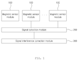
- FIG. 1 is a diagram illustrating the configuration of an interference correction type single-point detection current sensor for multiple busbars in accordance with an embodiment of the present invention
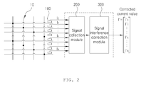
- FIG. 2 is a diagram illustrating a process of measuring current through the interference correction type single-point detection current sensor for multiple busbars in accordance with an embodiment of the present invention.
- the interference correction type single-point detection current sensor for multiple busbars in accordance with an embodiment of the present invention may be configured to include magnetic sensor modules 100, a signal collection module 200, and a signal interference correction module 300. More specifically, in the interference correction type single-point detection current sensor for multiple busbars in accordance with an embodiment of the present invention, as illustrated in FIG.
- the N magnetic sensor modules 100 installed adjacent to respective N busbars 10 may measure the amounts of current I 0 , I 1 , ..., I n , ..., I N in their respective locations.
- the signal collection module 200 may collect the measured amounts (measured signals) and transfer the collected amounts to the signal interference correction module 300.
- the signal interference correction module 300 may derive corrected current values I' 0 , I' 1 , ..., I' n , ..., I' N from which interference has been removed by calculating the amount of interference between the busbars.
- the magnetic sensor modules 100 are brought in insulation contact with or installed adjacent to the plurality of respective busbars 10, and they may measure currents flowing into the busbars 10 using magnetic sensors and output the measured currents. Since the magnetic sensor modules 100 are installed in the respective busbars, the magnetic sensor modules 100 and the busbars 10 may be configured to have the same number.
- the magnetic sensor modules 100 may function to convert magnetic field lines, generated by currents flowing into the multiple busbars 10, into electrical signals.
- FIG. 3 is a diagram illustrating the current measurement method of the magnetic sensor module in the interference correction type single-point detection current sensor for multiple busbars in accordance with an embodiment of the present invention. As illustrated in FIG. 3 , when current flows into the busbar 10, a magnetic field line is formed according to the right-handed screw rule.
- the magnetic sensor module 100 may convert the magnetic field line into an electrical signal and measure current flowing into the busbar 10.
- the magnetic sensor module 100 may be configured to include a magnetic sensor which is brought in insulation contact with or installed adjacent to the busbar 10 and which collects a magnetic field line generated by current flowing into the busbar 10 and a signal analysis circuit which interprets a signal collected by the magnetic sensor and calculates back to information about current that flows into the busbar 10.
- the magnetic sensor may use a hall sensor, but is not limited thereto. Various sensors may be used as the magnetic sensor.
- FIG. 4 is a diagram illustrating a case where interference is generated due to current that flows into a busbar adjacent to a single busbar in the interference correction type single-point detection current sensor for multiple busbars in accordance with an embodiment of the present invention.
- a magnetic sensor module 101 mounted on a busbar 11 whose amount of current is to be measured is also influenced by a magnetic field that is subject to interference attributable to current flowing into an adjacent busbar 12 in addition to current flowing into the corresponding busbar 11.
- an accurately corrected current value from which interference has been removed can be derived using an interference coefficient, formulated or modeled from a previously measured value, in a measured signal measured by each busbar 10 by including the signal collection module 200 and the signal interference correction module 300.
- the signal collection module 200 may function to collect measured signals output by the plurality of magnetic sensor modules 100 and transfer the collected signals to the signal interference correction module 300.
- the signal interference correction module 300 may derive corrected current values from which interference has been removed by calculating the amounts of interference between the plurality of busbars 10 in the signal collected by the signal collection module 300.
- FIG. 5 is a diagram illustrating a detailed configuration of a signal interference correction module in the interference correction type single-point detection current sensor for multiple busbars in accordance with an embodiment of the present invention.
- the signal interference correction module 300 of the interference correction type single-point detection current sensor for multiple busbars in accordance with an embodiment of the present invention may be configured to further include an interference coefficient matrix generation unit 310, an interference coefficient derivation unit 320, and a correction current value calculation unit 330.
- the signal interference correction module 300 may be configured to include interference correction memory 340.
- the interference coefficient matrix generation unit 310 may generate an interference coefficient matrix.
- the interference coefficient may be represented by h n,m , which means the amount of current that flows into an n th busbar 10 and that interferes with an m th busbar 10.
- FIG. 6 is a diagram illustrating a structure for modeling an interference equation in the interference correction type single-point detection current sensor for multiple busbars in accordance with an embodiment of the present invention. As illustrated in FIG. 6 , the amount of interference current measured by an (n+1) th magnetic sensor modules 100 due to current I' n actually flowing into the n th busbar 10 may be represented by h n , n+1 *I'n.
- current In measured by the n th busbar 10 may be represented by the amounts of interference current h 0 , n*I' 0 + h 1 , n *I' 1 + h 2 , n*I' 2 ... based on the amount of current I'n actually flowing into the n th busbar 10 and the amounts of current I' 0 , I' 1 , I' n-1 , and I' n+1 flowing into adjacent busbars 10.
- a measured current I may be equal to H*I' (a value obtained by multiplying actual current by an interference coefficient) according to an interference coefficient matrix H (refer to Equation 1 and a matrix below). That is, the measured current I may be considered to be a value influenced by interference attributable to the actual current I' that flows into the adjacent busbars 10.
- the interference coefficient matrix H may be defined in a table form by measuring a temperature and the distance through experiments.
- h 00 , h 11 , h 22 , and h NN denote ratios of the busbars 10 to be measured which are influenced by the respective busbars 10 and each may be 1, but may not be 1 depending on variables, such as a temperature, the amount of current, and the distance.
- the aforementioned interference coefficient matrix may be derived in an equation form according to the physical shape of the busbars 10 and the magnetic sensor modules 100 or may be derived by measurement in an actual environment. Furthermore, the aforementioned interference coefficient matrix may be featured according to environment variables, such as a temperature, the distance from a busbar, and the intensity of a magnetic flux, and a value in an environment in which measurement is not performed may be estimated through an interpolation method.
- I current measured by the magnetic sensor module
- h n, m an interference coefficient of current that flows into the n th busbar and that interferes with the m th busbar
- I' actual current
- n order of a busbar to be measured
- I 0 h 1,0 *I' 1 . That is, if current of 0.1 A is measured in the No.0 busbar 10 when an actual current of 1 A flows into the No.1 busbar 10, the No.0 busbar 10 is subject to interference of 10% due to the No.1 busbar 10. In this case, an interference coefficient h 1.0 becomes 0.1.
- busbars 10 are assumed to be very regularly installed, such an interference coefficient has a basic physical difference attributable to the distance between the busbars 10 and the distance between the magnetic sensor module 100 and the busbar 10. Accordingly, an interference coefficient needs to be calculated in each of the regularly configured busbars 10.
- the interference coefficient may differ depending on a temperature, the intensity of a magnetic flux (the amount of current), and the distance between a measured location and the busbar 10.
- a plurality of the interference coefficient matrices may be generated in each predetermined unit within a predetermined range of one or more variables selected from the group consisting of a temperature, the amount of current, and the distance between a measured location and the busbar 10.
- the plurality of generated interference coefficient matrices may be stored in the interference correction memory 340 or another separate memory.
- the interference coefficient may be measured based on a temperature and the intensity of a magnetic flux.
- the amount of physical interference is proportional to the amount of current, but may be different depending on the arrangement of busbars and a degree that interference is shielded.
- the matrix H according to a temperature and the amount of current may be derived by measuring the interference coefficient using a different amount of current for each temperature in the aforementioned experiments, and a coefficient may be extracted using an interpolation method with respect to a required part and may be used. Accordingly, a plurality of the matrices H may be present with respect to a temperature value and a current value.
- Input for selecting the actual coefficient includes a temperature and the intensity of current. Reference may be made to a coefficient corresponding to a temperature value suitable to a matrix H using the temperature value measured by a temperature sensor. As a similar method, a matrix value for the intensity of current has only to be selected based on the current I measured after a temperature value is determined.
- the aforementioned experiments correspond to a case where the matrices were measured using the amounts of current 1 A, 10 A, 25 A, and 50 A at temperatures of -40 degrees, -20 degrees, 0 degrees, 20 degrees, 40 degrees, 60 degrees, and 80 degrees with respect to the busbar 10 of 50 A standard, which is represented by H(T, C) for convenience sake.
- T is assumed to be a temperature
- C is assumed to be the amount of current.
- the interference coefficient matrix may be modeled based on the distance from the busbar and the amount of current measured in the busbar because a magnetic flux density B is in inverse proportion to the distance and is proportional to the amount of current.
- the interference coefficient matrix may be modeled and generated according to the following equation.
- B a magnetic flux density
- u 0 permeability in vacuum
- I current
- r the distance from a conductor (the distance from the busbar or an adjacent busbar)
- dl the curvilinear integral of a current direction
- r ⁇ a unit vector in a direction r
- each element h n, m of the matrix H may be considered to be a function, such as each distance, current, shielding, or temperature.
- the element may be determined by performing measurement for each temperature, for each current, and for each distance, performing measurement in the state in which the busbar 10 has been installed, or performing modeling.
- the interference coefficient derivation unit 320 may derive the interference coefficient of a corresponding busbar 10 using an interference coefficient matrix or an interpolation method.
- the correction current value calculation unit 330 may derive a corrected current value using a corresponding interference coefficient.
- the interference correction memory 340 may store the interference coefficient matrix generated by the interference coefficient matrix generation unit and an interference correction equation for deriving the corrected current value using an interference coefficient.
- the interference coefficient derivation unit 320 and the correction current value calculation unit 330 may read a value necessary to correct the interference of a measured signal from the interference correction memory 340 and calculate the corrected current value.
- an actual interference coefficient having sufficient accuracy may be obtained by taking into consideration only interference with a secondarily adjacent busbar because interference in the busbar 10 is rapidly attenuated according to the distance. Accordingly, the actual interference coefficient may be represented very simply as in the following equation and the matrix.
- I n h n - 2 , n * I ⁇ n - 2 + h n - 1 , n * I ⁇ n - 1 + h n , n * I ⁇ n + h n + 1 , n * I ⁇ n + 1 + h n + 2 , n * I ⁇ n + 2 .
- I current measured by the magnetic sensor module
- h n, m the interference coefficient of current that flows into the n th busbar and that interferes with the m th busbar
- I' an actual current
- n order of a busbar to be measured
- the above example illustrates an example in which the interference of a signal sampled on a time axis has been removed. If the interference of current remains constant for a short time, the amount of currents I' and I may be converted into complex numbers by taking a phase into consideration and calculated at once without calculating them for each current sampling value, thereby being capable of reducing a total computation load.
- FIG. 7 is a diagram illustrating the configuration of an interference correction type single-point detection current sensor for multiple busbars in accordance with another embodiment of the present invention.
- the interference correction type single-point detection current sensor for multiple busbars in accordance with another embodiment of the present invention may be configured to further include a temperature measurement module 400.
- a plurality of interference coefficient matrices may be generated in each predetermined unit within a predetermined temperature range and stored.
- the signal interference correction module 300 may derive a corrected current value using an interference coefficient matrix that complies with a temperature measured by the temperature measurement module 400.
- the single-point detection current sensor may be configured to further include a measurement error correction module 500 for deriving a measurement error correction value for each sensor by calculating environment variables, including a temperature, the distance from the busbar, and the intensity of a magnetic flux, with respect to a measured signal output by the magnetic sensor module.
- the signal interference correction module 300 may derive a corrected current value based on a measurement error correction value derived by the measurement error correction module.
- Each of the magnetic sensor modules 100 may have an error attributable to environment variables, such as a temperature, the distance, and the intensity of a magnetic flux, and thus may derive a measurement error correction variable according to environment variables, such as a temperature and the distance, by comparing the measured amount of current, measured by each busbar not having interference, with the actual amount of current.
- environment variables such as a temperature and the distance
- Such a measurement error correction variable may be stored in separate memory and used.
- busbar 11 busbars to be measured 12: adjacent busbar 100: magnetic sensor module 101: adjacent magnetic sensor module 102: adjacent magnetic sensor module 200: signal collection module 300: signal interference correction module 310: interference coefficient matrix generation unit 320: interference coefficient derivation unit 330: correction current value calculation unit 340: interference correction memory 400: temperature measurement module 500: measurement error correction module
Landscapes
- Physics & Mathematics (AREA)
- General Physics & Mathematics (AREA)
- Condensed Matter Physics & Semiconductors (AREA)
- Measuring Instrument Details And Bridges, And Automatic Balancing Devices (AREA)
- Measurement Of Current Or Voltage (AREA)
Abstract
Description
- The present invention relates to a single point detection current sensor and, more particularly, to an interference correction type single-point detection current sensor for multiple busbars.
- A method of measuring the amount of current in a contactless way in a panel board and a switch board includes a method using a current transformer and a method using a magnetic sensor. A method using a circular core as in a current transformer is a method of measuring the amount of current through induced electromotive force according to an induced magnetic flux that is formed in the core itself. Such a method has relatively small interference with other power lines, but requires a great installation space because an induced magnetic flux is formed while circulating the core. Furthermore, such a method is vulnerable to a mechanical deformation attributable to vibration or a mechanical shock and has a safety problem in installation and between control systems in an environment in which insulation has not been provided as in a busbar.
- In contrast, the magnetic sensor method is a method of disposing sensors capable of measuring a magnetic flux, such as hall sensors, on the periphery of busbars, directly measuring the amount of a magnetic flux, and converting the measured amount into the amount of current (refer to
Korean Patent Application Nos. 10-2009-0075419 10-2012-0028306 - The inventor of the present invention has developed a current sensor having improved measurement accuracy by removing interference occurring between busbars while maintaining the advantage of the magnetic sensor method in order to measure the amount of current in an environment in which a plurality of busbars is concentrated (multiple busbars).
- The present invention has been proposed in order to solve the above problems of the existing proposed methods, and an object of the present invention is to provide an interference correction type single-point detection current sensor for multiple busbars, which does not have interference between lines and has significantly improved accuracy in measuring the amount of current by including a signal interference correction module for deriving corrected current values from which interference has been removed by calculating the amounts of interference between a plurality of busbars.
- Another object of the present invention is to provide an interference correction type single-point detection current sensor for multiple busbars, wherein the signal interference correction module is configured to include an interference coefficient matrix generation unit, an interference coefficient derivation unit, and a correction current value calculation unit, thereby being capable of deriving a corrected current value from which interference is simply removed based on an interference coefficient matrix and calculation.
- Yet another object of the present invention is to provide an interference correction type single-point detection current sensor for multiple busbars, wherein a plurality of interference coefficient matrices is generated according to a temperature, the amount of current, the location where current is measured, and the distance between busbars, the plurality of generated interference coefficient matrices is stored, and an interference coefficient matrix suitable for a corresponding temperature, amount of current, and distance is used, thereby minimizing the occurrence of an error attributable to various variables.
- An interference correction type single-point detection current sensor for multiple busbars according to an aspect of the present invention for accomplishing the above objects includes a plurality of magnetic sensor modules which are brought in insulation contact with or installed adjacent to a plurality of respective busbars, measure currents flowing into the busbars using magnetic sensors, and output the measured currents; a signal collection module which collects the measured signals output by the plurality of magnetic sensor modules; and a signal interference correction module which derives corrected current values from which interference has been removed by calculating the amounts of interference between the plurality of busbars in the signals collected by the signal collection module.
- Preferably, the magnetic sensor module may be configured to include the magnetic sensor which is brought in insulation contact with or installed adjacent to the busbar and collects a magnetic field line generated by a current flowing into the busbar and a signal analysis circuit which calculates back to information about a current that flows into the busbar by analyzing a signal collected by the magnetic sensor.
- Preferably, the signal interference correction module may be configured to include an interference coefficient matrix generation unit which generates an interference coefficient matrix; an interference coefficient derivation unit which derives the interference coefficient of a corresponding busbar using the interference coefficient matrix or an interpolation method; and a correction current value calculation unit which derives the corrected current value using the derived corresponding interference coefficient.
- More preferably, the signal interference correction module may further include interference correction memory which stores an interference correction equation for deriving the corrected current value using the interference coefficient matrix generated by the interference coefficient matrix generation unit and the interference coefficient. The interference coefficient derivation unit and the correction current value calculation unit may read a value necessary to correct the interference of the measured signal from the interference correction memory and calculate the corrected current value.
- More preferably, a plurality of the interference coefficient matrices may be generated in each predetermined unit within a predetermined range of one or more variables selected from a group including a temperature, current, and measured location, and distance between the busbars.
- Preferably, the interference coefficient matrix may be modeled and generated according to the following equation.

(wherein B = a magnetic flux density, u0 = permeability in vacuum, I = current, r = a distance from a conductor (a distance from the busbar or an adjacent busbar), dl - a curvilinear integral of a current direction, and r^ = a unit vector in a direction r) - Preferably, the single-point detection current sensor may further include a temperature measurement module. A plurality of interference coefficient matrices may be generated in each predetermined unit within a predetermined temperature range, and the signal interference correction module may derive the corrected current value using the interference coefficient matrix that complies with a temperature measured by the temperature measurement module.
- Preferably, the single-point detection current sensor may further include a measurement error correction module which derives the measurement error correction value of each sensor by calculating environment variables, including a temperature, distance from the busbar, and intensity of a magnetic flux in the measured signal output by the magnetic sensor module. The signal interference correction module may derive the corrected current value based on the measurement error correction value derived by the measurement error correction module.
- In accordance with the interference correction type single-point detection current sensor for multiple busbars proposed by the present invention, since the signal interference correction module for deriving corrected current values from which interference has been removed by calculating the amounts of interference between a plurality of busbars is included, interference between lines is removed, and accuracy in measuring the amount of current is significantly improved.
- Furthermore, in accordance with the present invention, a corrected current value from which interference is simply removed can be derived based on an interference coefficient matrix and calculation because the signal interference correction module is configured to include an interference coefficient matrix generation unit, an interference coefficient derivation unit, and a correction current value calculation unit.
- Furthermore, in accordance with the present invention, the occurrence of an error attributable to various variables can be minimized because a plurality of interference coefficient matrices is generated according to a temperature, the amount of current, the location where current is measured, and the distance between busbars, the plurality of generated interference coefficient matrices is stored, and an interference coefficient matrix suitable for a corresponding temperature, amount of current, and distance is used.
-
-
FIG. 1 is a diagram illustrating the configuration of an interference correction type single-point detection current sensor for multiple busbars in accordance with an embodiment of the present invention. -
FIG. 2 is a diagram illustrating a process of measuring current through the interference correction type single-point detection current sensor for multiple busbars in accordance with an embodiment of the present invention. -
FIG. 3 is a diagram illustrating the current measurement method of a magnetic sensor module in the interference correction type single-point detection current sensor for multiple busbars in accordance with an embodiment of the present invention. -
FIG. 4 is a diagram illustrating a case where interference is generated due to current that flows into a busbar adjacent to a single busbar in the interference correction type single-point detection current sensor for multiple busbars in accordance with an embodiment of the present invention. -
FIG. 5 is a diagram illustrating a detailed configuration of a signal interference correction module in the interference correction type single-point detection current sensor for multiple busbars in accordance with an embodiment of the present invention. -
FIG. 6 is a diagram illustrating a structure for modeling an interference equation in the interference correction type single-point detection current sensor for multiple busbars in accordance with an embodiment of the present invention. -
FIG. 7 is a diagram illustrating the configuration of an interference correction type single-point detection current sensor for multiple busbars in accordance with another embodiment of the present invention. - Hereinafter, preferred embodiments are described in detail with reference to the accompanying drawings so that those skilled in the art to which the present invention pertains may easily practice the present invention. In this case, in describing the preferred embodiments of the present invention in detail, a detailed description of the known functions or elements will be omitted if it is deemed to make the gist of the present invention unnecessarily vague. Furthermore, the same reference numerals designate elements having similar functions and operations throughout the drawings.
- In addition, throughout the specification, when it is described that one element is 'connected' to the other element, the one element may be 'directly connected' to the other element or 'indirectly connected' to the other element through another element. Furthermore, when it is described that one element 'includes' another element, it means that the one element does not exclude another element, but may include other elements, unless otherwise described.
-
FIG. 1 is a diagram illustrating the configuration of an interference correction type single-point detection current sensor for multiple busbars in accordance with an embodiment of the present invention, andFIG. 2 is a diagram illustrating a process of measuring current through the interference correction type single-point detection current sensor for multiple busbars in accordance with an embodiment of the present invention. As illustrated inFIG. 1 , the interference correction type single-point detection current sensor for multiple busbars in accordance with an embodiment of the present invention may be configured to includemagnetic sensor modules 100, asignal collection module 200, and a signalinterference correction module 300. More specifically, in the interference correction type single-point detection current sensor for multiple busbars in accordance with an embodiment of the present invention, as illustrated inFIG. 2 , the Nmagnetic sensor modules 100 installed adjacent torespective N busbars 10 may measure the amounts of current I0, I1, ..., In, ..., IN in their respective locations. Thesignal collection module 200 may collect the measured amounts (measured signals) and transfer the collected amounts to the signalinterference correction module 300. The signalinterference correction module 300 may derive corrected current values I'0, I'1, ..., I'n, ..., I'N from which interference has been removed by calculating the amount of interference between the busbars. Each of the elements of the single-point detection current sensor proposed by the present invention is described below. - The
magnetic sensor modules 100 are brought in insulation contact with or installed adjacent to the plurality ofrespective busbars 10, and they may measure currents flowing into thebusbars 10 using magnetic sensors and output the measured currents. Since themagnetic sensor modules 100 are installed in the respective busbars, themagnetic sensor modules 100 and thebusbars 10 may be configured to have the same number. Themagnetic sensor modules 100 may function to convert magnetic field lines, generated by currents flowing into themultiple busbars 10, into electrical signals.FIG. 3 is a diagram illustrating the current measurement method of the magnetic sensor module in the interference correction type single-point detection current sensor for multiple busbars in accordance with an embodiment of the present invention. As illustrated inFIG. 3 , when current flows into thebusbar 10, a magnetic field line is formed according to the right-handed screw rule. Themagnetic sensor module 100 may convert the magnetic field line into an electrical signal and measure current flowing into thebusbar 10. - In accordance with an embodiment of the present invention, the
magnetic sensor module 100 may be configured to include a magnetic sensor which is brought in insulation contact with or installed adjacent to thebusbar 10 and which collects a magnetic field line generated by current flowing into thebusbar 10 and a signal analysis circuit which interprets a signal collected by the magnetic sensor and calculates back to information about current that flows into thebusbar 10. The magnetic sensor may use a hall sensor, but is not limited thereto. Various sensors may be used as the magnetic sensor. -
FIG. 4 is a diagram illustrating a case where interference is generated due to current that flows into a busbar adjacent to a single busbar in the interference correction type single-point detection current sensor for multiple busbars in accordance with an embodiment of the present invention. As illustrated inFIG. 4 , ifseveral busbars 10 are disposed as in a common switch board or panel board environment, amagnetic sensor module 101 mounted on abusbar 11 whose amount of current is to be measured is also influenced by a magnetic field that is subject to interference attributable to current flowing into anadjacent busbar 12 in addition to current flowing into thecorresponding busbar 11. This may be a further serious problem if the distance between thebusbars 10 is close, if current flowing into an adjacent busbar is strong, or if perfect shielding is difficult due to a problem, such as the discharging of high voltage. Furthermore, although physical shielding is performed, a certain amount of an interference phenomenon is generated because a leaking magnetic field is not perfectly shielded. In order to solve such a problem, the inventor of the present invention proposes that an accurately corrected current value from which interference has been removed can be derived using an interference coefficient, formulated or modeled from a previously measured value, in a measured signal measured by eachbusbar 10 by including thesignal collection module 200 and the signalinterference correction module 300. - The
signal collection module 200 may function to collect measured signals output by the plurality ofmagnetic sensor modules 100 and transfer the collected signals to the signalinterference correction module 300. - The signal
interference correction module 300 may derive corrected current values from which interference has been removed by calculating the amounts of interference between the plurality ofbusbars 10 in the signal collected by thesignal collection module 300. -
FIG. 5 is a diagram illustrating a detailed configuration of a signal interference correction module in the interference correction type single-point detection current sensor for multiple busbars in accordance with an embodiment of the present invention. As illustrated inFIG. 5 , the signalinterference correction module 300 of the interference correction type single-point detection current sensor for multiple busbars in accordance with an embodiment of the present invention may be configured to further include an interference coefficientmatrix generation unit 310, an interferencecoefficient derivation unit 320, and a correction currentvalue calculation unit 330. In some embodiments the signalinterference correction module 300 may be configured to includeinterference correction memory 340. - The interference coefficient
matrix generation unit 310 may generate an interference coefficient matrix. The interference coefficient may be represented by hn,m, which means the amount of current that flows into an nth busbar 10 and that interferes with an mth busbar 10.FIG. 6 is a diagram illustrating a structure for modeling an interference equation in the interference correction type single-point detection current sensor for multiple busbars in accordance with an embodiment of the present invention. As illustrated inFIG. 6 , the amount of interference current measured by an (n+1)thmagnetic sensor modules 100 due to current I'n actually flowing into the nth busbar 10 may be represented by hn,n+1*I'n. Accordingly, current In measured by the nth busbar 10 may be represented by the amounts of interference current h0, n*I'0+ h1, n*I'1+ h2, n*I'2... based on the amount of current I'n actually flowing into the nth busbar 10 and the amounts of current I'0, I'1, I'n-1, and I'n+1 flowing intoadjacent busbars 10. - Assuming that a matrix indicative of current actually flowing into each
busbar 10 is I' and a matrix indicative of current measured by themagnetic sensor modules 100 is I, a measured current I may be equal to H*I' (a value obtained by multiplying actual current by an interference coefficient) according to an interference coefficient matrix H (refer toEquation 1 and a matrix below). That is, the measured current I may be considered to be a value influenced by interference attributable to the actual current I' that flows into theadjacent busbars 10. The interference coefficient matrix H may be defined in a table form by measuring a temperature and the distance through experiments. If H is the function of I', that is, if H is influenced by I', I' may be calculated as a converging value by repeatedly calculating I=H-1*I and obtaining H after obtaining h in the state in which the initial value of I' is set to I.
- h00, h11, h22, and hNN denote ratios of the
busbars 10 to be measured which are influenced by therespective busbars 10 and each may be 1, but may not be 1 depending on variables, such as a temperature, the amount of current, and the distance. The aforementioned interference coefficient matrix may be derived in an equation form according to the physical shape of thebusbars 10 and themagnetic sensor modules 100 or may be derived by measurement in an actual environment. Furthermore, the aforementioned interference coefficient matrix may be featured according to environment variables, such as a temperature, the distance from a busbar, and the intensity of a magnetic flux, and a value in an environment in which measurement is not performed may be estimated through an interpolation method. - Experimentally, if current is made sequentially flow into the busbars and measured, when current of 1 A flows into only a No.1
busbar 10,
that is, if an actual current (I') matrix is
a measured current I0 in a No. 0 busbar is I0=h0,0*I'0+ h1,0*I'1+ h2,0*I'2+...+ hn,0*I'n+...+ hN,0*I'N. - (In this case, I = current measured by the magnetic sensor module, hn, m = an interference coefficient of current that flows into the nth busbar and that interferes with the mth busbar, I' = actual current, n = order of a busbar to be measured)
- If the actual current is substituted in the measured current, I0=h1,0*I'1. That is, if current of 0.1 A is measured in the No.0
busbar 10 when an actual current of 1 A flows into the No.1busbar 10, the No.0busbar 10 is subject to interference of 10% due to the No.1busbar 10. In this case, an interference coefficient h1.0 becomes 0.1. - Meanwhile, although the
busbars 10 are assumed to be very regularly installed, such an interference coefficient has a basic physical difference attributable to the distance between thebusbars 10 and the distance between themagnetic sensor module 100 and thebusbar 10. Accordingly, an interference coefficient needs to be calculated in each of the regularly configuredbusbars 10. - Meanwhile, the interference coefficient may differ depending on a temperature, the intensity of a magnetic flux (the amount of current), and the distance between a measured location and the
busbar 10. Preferably, a plurality of the interference coefficient matrices may be generated in each predetermined unit within a predetermined range of one or more variables selected from the group consisting of a temperature, the amount of current, and the distance between a measured location and thebusbar 10. The plurality of generated interference coefficient matrices may be stored in theinterference correction memory 340 or another separate memory. - That is, the interference coefficient may be measured based on a temperature and the intensity of a magnetic flux. The amount of physical interference is proportional to the amount of current, but may be different depending on the arrangement of busbars and a degree that interference is shielded. The matrix H according to a temperature and the amount of current may be derived by measuring the interference coefficient using a different amount of current for each temperature in the aforementioned experiments, and a coefficient may be extracted using an interpolation method with respect to a required part and may be used. Accordingly, a plurality of the matrices H may be present with respect to a temperature value and a current value.
- Input for selecting the actual coefficient includes a temperature and the intensity of current. Reference may be made to a coefficient corresponding to a temperature value suitable to a matrix H using the temperature value measured by a temperature sensor. As a similar method, a matrix value for the intensity of current has only to be selected based on the current I measured after a temperature value is determined. For example, the aforementioned experiments correspond to a case where the matrices were measured using the amounts of current 1 A, 10 A, 25 A, and 50 A at temperatures of -40 degrees, -20 degrees, 0 degrees, 20 degrees, 40 degrees, 60 degrees, and 80 degrees with respect to the
busbar 10 of 50 A standard, which is represented by H(T, C) for convenience sake. In this case, T is assumed to be a temperature, and C is assumed to be the amount of current. With respect to such a combination, the matrix H has a total number of 4 (the number of types of the amounts of current)*7(the number of types of temperature) types=28 types. If a temperature when thebusbar 10 operates is about 40 degrees, the amount of current I'0 is 10A, and the amount of current I'1 is 20 A, H(T, C) results in H(T=40 degrees, C=10 A) because the first row of the matrix H is an interference coefficient attributable to I'0, and H(T, C) results in H(T=40 degrees, C=20 A) because the second row is an interference coefficient attributable to I'1. If a temperature or a current value is not included in the table, H(T, C) may be calculated using an interpolation method. - Mathematical modeling is possible because an influence attributable to the distance and the amount of current that belong to the interference coefficients corresponds to a physical phenomenon. The interference coefficient matrix may be modeled based on the distance from the busbar and the amount of current measured in the busbar because a magnetic flux density B is in inverse proportion to the distance and is proportional to the amount of current.
- That is, the interference coefficient matrix may be modeled and generated according to the following equation.

- (In this case, B = a magnetic flux density, u0 = permeability in vacuum, I = current, r = the distance from a conductor (the distance from the busbar or an adjacent busbar), dl = the curvilinear integral of a current direction, and r^ = a unit vector in a direction r)
- In summary, each element hn, m of the matrix H may be considered to be a function, such as each distance, current, shielding, or temperature. The element may be determined by performing measurement for each temperature, for each current, and for each distance, performing measurement in the state in which the
busbar 10 has been installed, or performing modeling. - The interference
coefficient derivation unit 320 may derive the interference coefficient of a correspondingbusbar 10 using an interference coefficient matrix or an interpolation method. The correction currentvalue calculation unit 330 may derive a corrected current value using a corresponding interference coefficient. - Furthermore, the
interference correction memory 340 may store the interference coefficient matrix generated by the interference coefficient matrix generation unit and an interference correction equation for deriving the corrected current value using an interference coefficient. The interferencecoefficient derivation unit 320 and the correction currentvalue calculation unit 330 may read a value necessary to correct the interference of a measured signal from theinterference correction memory 340 and calculate the corrected current value. - Meanwhile, an actual interference coefficient having sufficient accuracy may be obtained by taking into consideration only interference with a secondarily adjacent busbar because interference in the
busbar 10 is rapidly attenuated according to the distance. Accordingly, the actual interference coefficient may be represented very simply as in the following equation and the matrix.
- (In this case, I = current measured by the magnetic sensor module, hn, m = the interference coefficient of current that flows into the nth busbar and that interferes with the mth busbar, I' = an actual current, and n = order of a busbar to be measured)
- The above example illustrates an example in which the interference of a signal sampled on a time axis has been removed. If the interference of current remains constant for a short time, the amount of currents I' and I may be converted into complex numbers by taking a phase into consideration and calculated at once without calculating them for each current sampling value, thereby being capable of reducing a total computation load.
-
FIG. 7 is a diagram illustrating the configuration of an interference correction type single-point detection current sensor for multiple busbars in accordance with another embodiment of the present invention. As illustrated inFIG. 7 , the interference correction type single-point detection current sensor for multiple busbars in accordance with another embodiment of the present invention may be configured to further include atemperature measurement module 400. A plurality of interference coefficient matrices may be generated in each predetermined unit within a predetermined temperature range and stored. The signalinterference correction module 300 may derive a corrected current value using an interference coefficient matrix that complies with a temperature measured by thetemperature measurement module 400. - Furthermore, the single-point detection current sensor may be configured to further include a measurement
error correction module 500 for deriving a measurement error correction value for each sensor by calculating environment variables, including a temperature, the distance from the busbar, and the intensity of a magnetic flux, with respect to a measured signal output by the magnetic sensor module. The signalinterference correction module 300 may derive a corrected current value based on a measurement error correction value derived by the measurement error correction module. Each of themagnetic sensor modules 100 may have an error attributable to environment variables, such as a temperature, the distance, and the intensity of a magnetic flux, and thus may derive a measurement error correction variable according to environment variables, such as a temperature and the distance, by comparing the measured amount of current, measured by each busbar not having interference, with the actual amount of current. Such a measurement error correction variable may be stored in separate memory and used. - The present invention described above may be modified or applied in various ways by those skilled in the art to which the present invention pertains, and the scope of a technical spirit according to the present invention should be determined by the following claims.
<Description of the Reference Numerals> 10: busbar 11: busbars to be measured 12: adjacent busbar 100: magnetic sensor module 101: adjacent magnetic sensor module 102: adjacent magnetic sensor module 200: signal collection module 300: signal interference correction module 310: interference coefficient matrix generation unit 320: interference coefficient derivation unit 330: correction current value calculation unit 340: interference correction memory 400: temperature measurement module 500: measurement error correction module
Claims (8)
- An interference correction type single-point detection current sensor for multiple busbars, the single-point detection current sensor comprising:a plurality of magnetic sensor modules which are brought in insulation contact with or installed adjacent to a plurality of respective busbars, measure currents flowing into the busbars using magnetic sensors, and output the measured currents;a signal collection module which collects the measured signals output by the plurality of magnetic sensor modules; anda signal interference correction module which derives corrected current values from which interference has been removed by calculating amounts of interference between the plurality of busbars in the signals collected by the signal collection module.
- The single-point detection current sensor of claim 1, wherein the magnetic sensor module is configured to comprise:the magnetic sensor which is brought in insulation contact with or installed adjacent to the busbar and collects a magnetic field line generated by a current flowing into the busbar; anda signal analysis circuit which calculates back to information about a current that flows into the busbar by analyzing a signal collected by the magnetic sensor.
- The single-point detection current sensor of claim 1, wherein the signal interference correction module is configured to comprise:an interference coefficient matrix generation unit which generates an interference coefficient matrix;an interference coefficient derivation unit which derives an interference coefficient of a corresponding busbar using the interference coefficient matrix or an interpolation method; anda correction current value calculation unit which derives the corrected current value using the derived corresponding interference coefficient.
- The single-point detection current sensor of claim 3, wherein:the signal interference correction module further comprises interference correction memory which stores an interference correction equation for deriving the corrected current value using the interference coefficient matrix generated by the interference coefficient matrix generation unit and the interference coefficient, andthe interference coefficient derivation unit and the correction current value calculation unit read a value necessary to correct interference of the measured signal from the interference correction memory and calculate the corrected current value.
- The single-point detection current sensor of claim 3, wherein a plurality of the interference coefficient matrices is generated in each predetermined unit within a predetermined range of one or more variables selected from a group comprising a temperature, current, and measured location, and distance between the busbars.
- The single-point detection current sensor of claim 3, wherein the interference coefficient matrix is modeled and generated according to an equation below.

(wherein B = a magnetic flux density, u0 = permeability in vacuum, I = current, r = a distance from a conductor (a distance from the busbar or an adjacent busbar), dl + a curvilinear integral of a current direction, and r^ = a unit vector in a direction r) - The single-point detection current sensor of claim 1, further comprising a temperature measurement module,
wherein a plurality of interference coefficient matrices is generated in each predetermined unit within a predetermined temperature range, and
the signal interference correction module derives the corrected current value using the interference coefficient matrix that complies with a temperature measured by the temperature measurement module. - The single-point detection current sensor of claim 1, further comprising a measurement error correction module which derives a measurement error correction value of each sensor by calculating environment variables, comprising a temperature, distance from the busbar, and intensity of a magnetic flux in the measured signal output by the magnetic sensor module,
wherein the signal interference correction module derives the corrected current value based on the measurement error correction value derived by the measurement error correction module.
Applications Claiming Priority (2)
| Application Number | Priority Date | Filing Date | Title |
|---|---|---|---|
| KR1020130037123A KR101297200B1 (en) | 2013-04-04 | 2013-04-04 | Point detecting type current measuring device having function of compensating interference by adjacent bus bar |
| PCT/KR2014/002529 WO2014163318A1 (en) | 2013-04-04 | 2014-03-25 | Interference compensating single point detecting current sensor for a multiplex busbar |
Publications (3)
| Publication Number | Publication Date |
|---|---|
| EP2982994A1 true EP2982994A1 (en) | 2016-02-10 |
| EP2982994A4 EP2982994A4 (en) | 2016-11-30 |
| EP2982994B1 EP2982994B1 (en) | 2021-03-10 |
Family
ID=49220656
Family Applications (1)
| Application Number | Title | Priority Date | Filing Date |
|---|---|---|---|
| EP14780184.9A Not-in-force EP2982994B1 (en) | 2013-04-04 | 2014-03-25 | Interference compensating single point detecting current sensor for a multiplex busbar |
Country Status (8)
| Country | Link |
|---|---|
| US (1) | US9494621B2 (en) |
| EP (1) | EP2982994B1 (en) |
| JP (1) | JP6399415B2 (en) |
| KR (1) | KR101297200B1 (en) |
| CN (1) | CN104854461B (en) |
| AU (1) | AU2014250331A1 (en) |
| CA (1) | CA2895974A1 (en) |
| WO (1) | WO2014163318A1 (en) |
Cited By (1)
| Publication number | Priority date | Publication date | Assignee | Title |
|---|---|---|---|---|
| EP2899553A2 (en) * | 2014-01-21 | 2015-07-29 | Hitachi Metals, Ltd. | Electric current sensor |
Families Citing this family (30)
| Publication number | Priority date | Publication date | Assignee | Title |
|---|---|---|---|---|
| JP2016099292A (en) * | 2014-11-25 | 2016-05-30 | 日立金属株式会社 | Current detector and current detection method |
| KR101606031B1 (en) * | 2015-02-13 | 2016-03-24 | 주식회사 레티그리드 | Power quality measurement device and system based on separate phase measuring module |
| KR101623727B1 (en) * | 2015-02-13 | 2016-05-24 | 주식회사 레티그리드 | A power quality measurement device and power per load |
| US9686273B2 (en) * | 2015-02-24 | 2017-06-20 | Avatier Corporation | Aggregator technology without usernames and passwords |
| KR101627595B1 (en) * | 2015-04-28 | 2016-06-07 | 주식회사 비엠티 | Pointing current sensor for distribution board and switching board |
| JP6522048B2 (en) * | 2017-05-31 | 2019-05-29 | 本田技研工業株式会社 | POWER DEVICE AND METHOD FOR MANUFACTURING POWER DEVICE |
| US10884031B2 (en) * | 2018-08-17 | 2021-01-05 | Allegro Microsystems, Llc | Current sensor system |
| US12055615B2 (en) * | 2019-03-13 | 2024-08-06 | Nidec Read Corporation | Detection value correction system, coefficient calculation method, and detection value correction method |
| JP7259586B2 (en) * | 2019-06-20 | 2023-04-18 | 株式会社デンソー | sensor unit |
| US11366142B2 (en) * | 2019-11-22 | 2022-06-21 | Schneider Electric USA, Inc. | Multi-device current measurement crosstalk compensation |
| US11226382B2 (en) | 2020-04-07 | 2022-01-18 | Allegro Microsystems, Llc | Current sensor system |
| JP7581693B2 (en) * | 2020-08-04 | 2024-11-13 | 株式会社アイシン | Current Sensors |
| CN112505386B (en) * | 2020-08-25 | 2022-09-02 | 中国电力科学研究院有限公司 | Method and system for detecting current value of direct current charging pile |
| US11614470B2 (en) * | 2020-11-05 | 2023-03-28 | U-Haul International, Inc. | Non-invasive current sensing device |
| KR102330399B1 (en) * | 2021-01-12 | 2021-11-23 | 김성진 | Busbar Module for High Frequency High Current Measurement and Current Measurement Method using The Same |
| CN113252960A (en) * | 2021-04-30 | 2021-08-13 | 南京工程学院 | External magnetic field interference suppression method suitable for direct-current power distribution network current sensor |
| US12352786B2 (en) | 2021-09-07 | 2025-07-08 | Allegro Microsystems, Llc | Current sensor system |
| US11656250B2 (en) | 2021-09-07 | 2023-05-23 | Allegro Microsystems, Llc | Current sensor system |
| KR102687202B1 (en) * | 2021-11-23 | 2024-07-19 | 국립한국교통대학교산학협력단 | A 3-Phase Current Detecting Device Using the Induction Coils |
| US11892476B2 (en) | 2022-02-15 | 2024-02-06 | Allegro Microsystems, Llc | Current sensor package |
| US12112865B2 (en) | 2022-03-15 | 2024-10-08 | Allegro Microsystems, Llc | Multiple branch bus bar for coreless current sensing application |
| US11940470B2 (en) | 2022-05-31 | 2024-03-26 | Allegro Microsystems, Llc | Current sensor system |
| CN114966160B (en) * | 2022-07-29 | 2022-10-25 | 浙江大学 | Laminated busbar and power device current detection device based on tunnel magnetoresistance |
| EP4394393B1 (en) * | 2022-12-28 | 2025-10-22 | Melexis Technologies SA | Current sensing with crosstalk immunuity |
| GB2625992A (en) * | 2023-01-03 | 2024-07-10 | Eaton Intelligent Power Ltd | Current measuring system for switching devices arranged in a matrix configuration |
| KR102794719B1 (en) * | 2024-08-29 | 2025-04-15 | 주식회사 루텍 | Measurement Device Having Detachable Thermometer Module |
| CN118897240B (en) * | 2024-09-30 | 2025-01-24 | 至驱汽车科技(上海)有限公司 | Sensor calibration device, sensor calibration method and electronic equipment |
| DE102025105223A1 (en) | 2025-02-12 | 2026-08-13 | Rittal Gmbh & Co. Kg | Touch protection for a busbar system with magnetic shielding |
| DE102025106164B3 (en) | 2025-02-19 | 2026-04-02 | Rittal Gmbh & Co. Kg | Touch protection arrangement for a busbar system with magnetically shielded connection adapter |
| CN121008212B (en) * | 2025-10-23 | 2025-12-30 | 深圳市迈斯泰克电子有限公司 | Clamp-on ammeter with multi-channel interference suppression function |
Family Cites Families (17)
| Publication number | Priority date | Publication date | Assignee | Title |
|---|---|---|---|---|
| FR2693275B1 (en) * | 1992-07-06 | 1994-08-19 | Alsthom Gec | Ground measurement device for high voltage overhead lines. |
| JP3461607B2 (en) * | 1995-02-28 | 2003-10-27 | 株式会社キューヘン | Method and apparatus for setting magnetic field influence coefficient |
| DE19910801B4 (en) * | 1999-03-11 | 2004-06-03 | Fraunhofer-Gesellschaft zur Förderung der angewandten Forschung e.V. | Device and method for measuring current |
| JP4245236B2 (en) | 1999-08-30 | 2009-03-25 | 株式会社エヌエフ回路設計ブロック | Current detection circuit |
| IT1314341B1 (en) * | 1999-12-29 | 2002-12-09 | Abb Ricerca Spa | CURRENT MEASURING DEVICE FOR LOW VOLTAGE POWER SWITCHES |
| JP2001289885A (en) * | 2000-04-03 | 2001-10-19 | Kyushu Electric Power Co Inc | Current / voltage measuring device in transmission / distribution line measurement system and transmission / distribution line measurement state monitoring method |
| JP2002162423A (en) * | 2000-11-28 | 2002-06-07 | Nishimu Electronics Industries Co Ltd | Transmission and distribution line current detection and electrical condition analyzer |
| JP2002333456A (en) | 2001-05-08 | 2002-11-22 | Mitsubishi Electric Corp | Current sensor |
| FR2872580B1 (en) * | 2004-06-30 | 2006-09-01 | Valeo Equip Electr Moteur | METHOD FOR MEASURING THE ELECTRICAL CURRENT IN A PLURALITY OF CONDUCTORS |
| US7205757B2 (en) * | 2004-09-02 | 2007-04-17 | Denso Corporation | High precision current sensor |
| KR100712614B1 (en) * | 2005-10-12 | 2007-04-30 | 일진전기 주식회사 | Current measuring device for correcting phase interference by adjacent wires, current measuring system using the current measuring device and its current measuring method |
| US7511485B2 (en) * | 2006-01-31 | 2009-03-31 | Hitachi, Ltd. | Magnetic field measurement method and system |
| JP4628987B2 (en) * | 2006-04-10 | 2011-02-09 | 矢崎総業株式会社 | Current sensor with temperature detection function |
| KR101067856B1 (en) | 2008-01-04 | 2011-09-27 | 주식회사 옥서스 | Control device for oxygen generator and control method using same |
| KR101341741B1 (en) | 2009-07-16 | 2013-12-16 | 아사히 가라스 가부시키가이샤 | Method for producing molten glass, vacuum degassing apparatus, and method for producing glass product |
| JP2013088349A (en) * | 2011-10-20 | 2013-05-13 | Alps Green Devices Co Ltd | Current sensor |
| KR101227653B1 (en) | 2012-10-04 | 2013-01-29 | 부흥시스템(주) | Method and system for calculating the correction factor of the voltage and current from the control on distribution power networks |
-
2013
- 2013-04-04 KR KR1020130037123A patent/KR101297200B1/en not_active Expired - Fee Related
-
2014
- 2014-03-25 EP EP14780184.9A patent/EP2982994B1/en not_active Not-in-force
- 2014-03-25 JP JP2016506226A patent/JP6399415B2/en not_active Expired - Fee Related
- 2014-03-25 CA CA2895974A patent/CA2895974A1/en not_active Abandoned
- 2014-03-25 CN CN201480003363.9A patent/CN104854461B/en not_active Expired - Fee Related
- 2014-03-25 US US14/404,256 patent/US9494621B2/en not_active Expired - Fee Related
- 2014-03-25 AU AU2014250331A patent/AU2014250331A1/en not_active Abandoned
- 2014-03-25 WO PCT/KR2014/002529 patent/WO2014163318A1/en not_active Ceased
Cited By (1)
| Publication number | Priority date | Publication date | Assignee | Title |
|---|---|---|---|---|
| EP2899553A2 (en) * | 2014-01-21 | 2015-07-29 | Hitachi Metals, Ltd. | Electric current sensor |
Also Published As
| Publication number | Publication date |
|---|---|
| US20160011239A1 (en) | 2016-01-14 |
| CA2895974A1 (en) | 2014-10-09 |
| JP2016515707A (en) | 2016-05-30 |
| KR101297200B1 (en) | 2013-08-29 |
| US9494621B2 (en) | 2016-11-15 |
| AU2014250331A1 (en) | 2015-07-02 |
| EP2982994A4 (en) | 2016-11-30 |
| CN104854461A (en) | 2015-08-19 |
| CN104854461B (en) | 2019-02-19 |
| EP2982994B1 (en) | 2021-03-10 |
| WO2014163318A1 (en) | 2014-10-09 |
| JP6399415B2 (en) | 2018-10-03 |
Similar Documents
| Publication | Publication Date | Title |
|---|---|---|
| EP2982994B1 (en) | Interference compensating single point detecting current sensor for a multiplex busbar | |
| US11022655B2 (en) | Method and control system for faulted phase detection | |
| KR101515478B1 (en) | Method for detecting arc by magnetic sensor and arc protection switching board using the same method | |
| EP2000811B1 (en) | Method for determining location of phase-to-earth fault | |
| US8145443B2 (en) | Fourier transform-based phasor estimation method and apparatus capable of eliminating influence of exponentially decaying DC offsets | |
| CN102495281B (en) | Method for measuring phasor frequency of power system | |
| EP3732760B1 (en) | Parameter free identification of fault location in multi- terminal power transmission lines | |
| US6466030B2 (en) | Systems and methods for locating faults on a transmission line with a single tapped load | |
| RU2631025C2 (en) | Detection of direction of weakly resistant short circuit to earth of average voltage with help of linear correlation | |
| US20170148300A1 (en) | Method for loose joint detection in medium voltage switchgears and medium voltage switchgear itself | |
| JP2017026559A (en) | Gas leak detection device and gas leak detection method | |
| EP3629437A1 (en) | Method and device for controlling at least one circuit breaker of a power system | |
| US20190296543A1 (en) | Method for detecting fault in power transmission line and protection system using the same | |
| CN110118912B (en) | Grey correlation analysis-based single-phase earth fault line selection method for arc suppression coil device-grounded power distribution network | |
| CN109932615A (en) | Single-phase cable fault location method and device | |
| Dobakhshari | Fast accurate fault location on transmission system utilizing wide-area unsynchronized measurements | |
| KR101488690B1 (en) | Method and current measuring device to measure current by cancelling adjacent current interference | |
| CN102053201A (en) | Multi-channel field standard electrical energy meter | |
| CN116430110A (en) | Current synchronous acquisition method, system, terminal equipment and storage medium | |
| Carmo et al. | Incipient fault localization using sheath and impedance-based method for single-bonded underground cables | |
| CN121633964A (en) | A method and apparatus for signal compensation of current transformers | |
| RU2540443C1 (en) | Method for determining place of failure on overhead transmission line | |
| JP4443099B2 (en) | Accident point search method for overhead distribution lines | |
| EP0214483B1 (en) | Method for measuring distance in digital distance relays | |
| WO2019035991A2 (en) | Nuclear instrumentation isolated output signal scaling method and system employing same |
Legal Events
| Date | Code | Title | Description |
|---|---|---|---|
| PUAI | Public reference made under article 153(3) epc to a published international application that has entered the european phase |
Free format text: ORIGINAL CODE: 0009012 |
|
| 17P | Request for examination filed |
Effective date: 20150603 |
|
| AK | Designated contracting states |
Kind code of ref document: A1 Designated state(s): AL AT BE BG CH CY CZ DE DK EE ES FI FR GB GR HR HU IE IS IT LI LT LU LV MC MK MT NL NO PL PT RO RS SE SI SK SM TR |
|
| AX | Request for extension of the european patent |
Extension state: BA ME |
|
| DAX | Request for extension of the european patent (deleted) | ||
| A4 | Supplementary search report drawn up and despatched |
Effective date: 20161103 |
|
| RIC1 | Information provided on ipc code assigned before grant |
Ipc: G01R 15/20 20060101AFI20161027BHEP Ipc: G01R 33/07 20060101ALI20161027BHEP Ipc: G01R 19/00 20060101ALI20161027BHEP |
|
| STAA | Information on the status of an ep patent application or granted ep patent |
Free format text: STATUS: EXAMINATION IS IN PROGRESS |
|
| 17Q | First examination report despatched |
Effective date: 20190509 |
|
| GRAP | Despatch of communication of intention to grant a patent |
Free format text: ORIGINAL CODE: EPIDOSNIGR1 |
|
| STAA | Information on the status of an ep patent application or granted ep patent |
Free format text: STATUS: GRANT OF PATENT IS INTENDED |
|
| INTG | Intention to grant announced |
Effective date: 20200930 |
|
| GRAS | Grant fee paid |
Free format text: ORIGINAL CODE: EPIDOSNIGR3 |
|
| GRAA | (expected) grant |
Free format text: ORIGINAL CODE: 0009210 |
|
| STAA | Information on the status of an ep patent application or granted ep patent |
Free format text: STATUS: THE PATENT HAS BEEN GRANTED |
|
| AK | Designated contracting states |
Kind code of ref document: B1 Designated state(s): AL AT BE BG CH CY CZ DE DK EE ES FI FR GB GR HR HU IE IS IT LI LT LU LV MC MK MT NL NO PL PT RO RS SE SI SK SM TR |
|
| REG | Reference to a national code |
Ref country code: GB Ref legal event code: FG4D |
|
| REG | Reference to a national code |
Ref country code: AT Ref legal event code: REF Ref document number: 1370411 Country of ref document: AT Kind code of ref document: T Effective date: 20210315 Ref country code: CH Ref legal event code: EP |
|
| REG | Reference to a national code |
Ref country code: IE Ref legal event code: FG4D |
|
| REG | Reference to a national code |
Ref country code: DE Ref legal event code: R096 Ref document number: 602014075594 Country of ref document: DE |
|
| REG | Reference to a national code |
Ref country code: LT Ref legal event code: MG9D |
|
| PG25 | Lapsed in a contracting state [announced via postgrant information from national office to epo] |
Ref country code: NO Free format text: LAPSE BECAUSE OF FAILURE TO SUBMIT A TRANSLATION OF THE DESCRIPTION OR TO PAY THE FEE WITHIN THE PRESCRIBED TIME-LIMIT Effective date: 20210610 Ref country code: BG Free format text: LAPSE BECAUSE OF FAILURE TO SUBMIT A TRANSLATION OF THE DESCRIPTION OR TO PAY THE FEE WITHIN THE PRESCRIBED TIME-LIMIT Effective date: 20210610 Ref country code: LT Free format text: LAPSE BECAUSE OF FAILURE TO SUBMIT A TRANSLATION OF THE DESCRIPTION OR TO PAY THE FEE WITHIN THE PRESCRIBED TIME-LIMIT Effective date: 20210310 Ref country code: HR Free format text: LAPSE BECAUSE OF FAILURE TO SUBMIT A TRANSLATION OF THE DESCRIPTION OR TO PAY THE FEE WITHIN THE PRESCRIBED TIME-LIMIT Effective date: 20210310 Ref country code: GR Free format text: LAPSE BECAUSE OF FAILURE TO SUBMIT A TRANSLATION OF THE DESCRIPTION OR TO PAY THE FEE WITHIN THE PRESCRIBED TIME-LIMIT Effective date: 20210611 Ref country code: FI Free format text: LAPSE BECAUSE OF FAILURE TO SUBMIT A TRANSLATION OF THE DESCRIPTION OR TO PAY THE FEE WITHIN THE PRESCRIBED TIME-LIMIT Effective date: 20210310 |
|
| REG | Reference to a national code |
Ref country code: AT Ref legal event code: MK05 Ref document number: 1370411 Country of ref document: AT Kind code of ref document: T Effective date: 20210310 |
|
| REG | Reference to a national code |
Ref country code: NL Ref legal event code: MP Effective date: 20210310 |
|
| PG25 | Lapsed in a contracting state [announced via postgrant information from national office to epo] |
Ref country code: SE Free format text: LAPSE BECAUSE OF FAILURE TO SUBMIT A TRANSLATION OF THE DESCRIPTION OR TO PAY THE FEE WITHIN THE PRESCRIBED TIME-LIMIT Effective date: 20210310 Ref country code: LV Free format text: LAPSE BECAUSE OF FAILURE TO SUBMIT A TRANSLATION OF THE DESCRIPTION OR TO PAY THE FEE WITHIN THE PRESCRIBED TIME-LIMIT Effective date: 20210310 Ref country code: RS Free format text: LAPSE BECAUSE OF FAILURE TO SUBMIT A TRANSLATION OF THE DESCRIPTION OR TO PAY THE FEE WITHIN THE PRESCRIBED TIME-LIMIT Effective date: 20210310 |
|
| PG25 | Lapsed in a contracting state [announced via postgrant information from national office to epo] |
Ref country code: NL Free format text: LAPSE BECAUSE OF FAILURE TO SUBMIT A TRANSLATION OF THE DESCRIPTION OR TO PAY THE FEE WITHIN THE PRESCRIBED TIME-LIMIT Effective date: 20210310 |
|
| PG25 | Lapsed in a contracting state [announced via postgrant information from national office to epo] |
Ref country code: SM Free format text: LAPSE BECAUSE OF FAILURE TO SUBMIT A TRANSLATION OF THE DESCRIPTION OR TO PAY THE FEE WITHIN THE PRESCRIBED TIME-LIMIT Effective date: 20210310 Ref country code: CZ Free format text: LAPSE BECAUSE OF FAILURE TO SUBMIT A TRANSLATION OF THE DESCRIPTION OR TO PAY THE FEE WITHIN THE PRESCRIBED TIME-LIMIT Effective date: 20210310 Ref country code: EE Free format text: LAPSE BECAUSE OF FAILURE TO SUBMIT A TRANSLATION OF THE DESCRIPTION OR TO PAY THE FEE WITHIN THE PRESCRIBED TIME-LIMIT Effective date: 20210310 Ref country code: AT Free format text: LAPSE BECAUSE OF FAILURE TO SUBMIT A TRANSLATION OF THE DESCRIPTION OR TO PAY THE FEE WITHIN THE PRESCRIBED TIME-LIMIT Effective date: 20210310 |
|
| REG | Reference to a national code |
Ref country code: CH Ref legal event code: PL |
|
| PG25 | Lapsed in a contracting state [announced via postgrant information from national office to epo] |
Ref country code: IS Free format text: LAPSE BECAUSE OF FAILURE TO SUBMIT A TRANSLATION OF THE DESCRIPTION OR TO PAY THE FEE WITHIN THE PRESCRIBED TIME-LIMIT Effective date: 20210710 Ref country code: PL Free format text: LAPSE BECAUSE OF FAILURE TO SUBMIT A TRANSLATION OF THE DESCRIPTION OR TO PAY THE FEE WITHIN THE PRESCRIBED TIME-LIMIT Effective date: 20210310 Ref country code: PT Free format text: LAPSE BECAUSE OF FAILURE TO SUBMIT A TRANSLATION OF THE DESCRIPTION OR TO PAY THE FEE WITHIN THE PRESCRIBED TIME-LIMIT Effective date: 20210712 Ref country code: ES Free format text: LAPSE BECAUSE OF FAILURE TO SUBMIT A TRANSLATION OF THE DESCRIPTION OR TO PAY THE FEE WITHIN THE PRESCRIBED TIME-LIMIT Effective date: 20210310 Ref country code: SK Free format text: LAPSE BECAUSE OF FAILURE TO SUBMIT A TRANSLATION OF THE DESCRIPTION OR TO PAY THE FEE WITHIN THE PRESCRIBED TIME-LIMIT Effective date: 20210310 Ref country code: RO Free format text: LAPSE BECAUSE OF FAILURE TO SUBMIT A TRANSLATION OF THE DESCRIPTION OR TO PAY THE FEE WITHIN THE PRESCRIBED TIME-LIMIT Effective date: 20210310 |
|
| REG | Reference to a national code |
Ref country code: DE Ref legal event code: R097 Ref document number: 602014075594 Country of ref document: DE |
|
| REG | Reference to a national code |
Ref country code: BE Ref legal event code: MM Effective date: 20210331 |
|
| PLBE | No opposition filed within time limit |
Free format text: ORIGINAL CODE: 0009261 |
|
| STAA | Information on the status of an ep patent application or granted ep patent |
Free format text: STATUS: NO OPPOSITION FILED WITHIN TIME LIMIT |
|
| PG25 | Lapsed in a contracting state [announced via postgrant information from national office to epo] |
Ref country code: DK Free format text: LAPSE BECAUSE OF FAILURE TO SUBMIT A TRANSLATION OF THE DESCRIPTION OR TO PAY THE FEE WITHIN THE PRESCRIBED TIME-LIMIT Effective date: 20210310 Ref country code: IE Free format text: LAPSE BECAUSE OF NON-PAYMENT OF DUE FEES Effective date: 20210325 Ref country code: MC Free format text: LAPSE BECAUSE OF FAILURE TO SUBMIT A TRANSLATION OF THE DESCRIPTION OR TO PAY THE FEE WITHIN THE PRESCRIBED TIME-LIMIT Effective date: 20210310 Ref country code: LI Free format text: LAPSE BECAUSE OF NON-PAYMENT OF DUE FEES Effective date: 20210331 Ref country code: LU Free format text: LAPSE BECAUSE OF NON-PAYMENT OF DUE FEES Effective date: 20210325 Ref country code: CH Free format text: LAPSE BECAUSE OF NON-PAYMENT OF DUE FEES Effective date: 20210331 Ref country code: AL Free format text: LAPSE BECAUSE OF FAILURE TO SUBMIT A TRANSLATION OF THE DESCRIPTION OR TO PAY THE FEE WITHIN THE PRESCRIBED TIME-LIMIT Effective date: 20210310 |
|
| 26N | No opposition filed |
Effective date: 20211213 |
|
| PG25 | Lapsed in a contracting state [announced via postgrant information from national office to epo] |
Ref country code: SI Free format text: LAPSE BECAUSE OF FAILURE TO SUBMIT A TRANSLATION OF THE DESCRIPTION OR TO PAY THE FEE WITHIN THE PRESCRIBED TIME-LIMIT Effective date: 20210310 |
|
| PG25 | Lapsed in a contracting state [announced via postgrant information from national office to epo] |
Ref country code: IT Free format text: LAPSE BECAUSE OF FAILURE TO SUBMIT A TRANSLATION OF THE DESCRIPTION OR TO PAY THE FEE WITHIN THE PRESCRIBED TIME-LIMIT Effective date: 20210310 |
|
| PG25 | Lapsed in a contracting state [announced via postgrant information from national office to epo] |
Ref country code: IS Free format text: LAPSE BECAUSE OF FAILURE TO SUBMIT A TRANSLATION OF THE DESCRIPTION OR TO PAY THE FEE WITHIN THE PRESCRIBED TIME-LIMIT Effective date: 20210710 |
|
| PG25 | Lapsed in a contracting state [announced via postgrant information from national office to epo] |
Ref country code: BE Free format text: LAPSE BECAUSE OF NON-PAYMENT OF DUE FEES Effective date: 20210331 |
|
| PG25 | Lapsed in a contracting state [announced via postgrant information from national office to epo] |
Ref country code: HU Free format text: LAPSE BECAUSE OF FAILURE TO SUBMIT A TRANSLATION OF THE DESCRIPTION OR TO PAY THE FEE WITHIN THE PRESCRIBED TIME-LIMIT; INVALID AB INITIO Effective date: 20140325 |
|
| PG25 | Lapsed in a contracting state [announced via postgrant information from national office to epo] |
Ref country code: CY Free format text: LAPSE BECAUSE OF FAILURE TO SUBMIT A TRANSLATION OF THE DESCRIPTION OR TO PAY THE FEE WITHIN THE PRESCRIBED TIME-LIMIT Effective date: 20210310 |
|
| PGFP | Annual fee paid to national office [announced via postgrant information from national office to epo] |
Ref country code: GB Payment date: 20230719 Year of fee payment: 10 |
|
| PGFP | Annual fee paid to national office [announced via postgrant information from national office to epo] |
Ref country code: FR Payment date: 20230929 Year of fee payment: 10 Ref country code: DE Payment date: 20230719 Year of fee payment: 10 |
|
| PG25 | Lapsed in a contracting state [announced via postgrant information from national office to epo] |
Ref country code: MK Free format text: LAPSE BECAUSE OF FAILURE TO SUBMIT A TRANSLATION OF THE DESCRIPTION OR TO PAY THE FEE WITHIN THE PRESCRIBED TIME-LIMIT Effective date: 20210310 |
|
| PG25 | Lapsed in a contracting state [announced via postgrant information from national office to epo] |
Ref country code: MT Free format text: LAPSE BECAUSE OF FAILURE TO SUBMIT A TRANSLATION OF THE DESCRIPTION OR TO PAY THE FEE WITHIN THE PRESCRIBED TIME-LIMIT Effective date: 20210310 |
|
| REG | Reference to a national code |
Ref country code: DE Ref legal event code: R119 Ref document number: 602014075594 Country of ref document: DE |
|
| GBPC | Gb: european patent ceased through non-payment of renewal fee |
Effective date: 20240325 |
|
| PG25 | Lapsed in a contracting state [announced via postgrant information from national office to epo] |
Ref country code: DE Free format text: LAPSE BECAUSE OF NON-PAYMENT OF DUE FEES Effective date: 20241001 |
|
| PG25 | Lapsed in a contracting state [announced via postgrant information from national office to epo] |
Ref country code: GB Free format text: LAPSE BECAUSE OF NON-PAYMENT OF DUE FEES Effective date: 20240325 |
|
| PG25 | Lapsed in a contracting state [announced via postgrant information from national office to epo] |
Ref country code: FR Free format text: LAPSE BECAUSE OF NON-PAYMENT OF DUE FEES Effective date: 20240331 |
|
| PG25 | Lapsed in a contracting state [announced via postgrant information from national office to epo] |
Ref country code: GB Free format text: LAPSE BECAUSE OF NON-PAYMENT OF DUE FEES Effective date: 20240325 Ref country code: FR Free format text: LAPSE BECAUSE OF NON-PAYMENT OF DUE FEES Effective date: 20240331 Ref country code: DE Free format text: LAPSE BECAUSE OF NON-PAYMENT OF DUE FEES Effective date: 20241001 |
|
| PG25 | Lapsed in a contracting state [announced via postgrant information from national office to epo] |
Ref country code: TR Free format text: LAPSE BECAUSE OF FAILURE TO SUBMIT A TRANSLATION OF THE DESCRIPTION OR TO PAY THE FEE WITHIN THE PRESCRIBED TIME-LIMIT Effective date: 20210310 |