EP2982910A1 - Indoor unit of air-conditioning apparatus - Google Patents
Indoor unit of air-conditioning apparatus Download PDFInfo
- Publication number
- EP2982910A1 EP2982910A1 EP15179383.3A EP15179383A EP2982910A1 EP 2982910 A1 EP2982910 A1 EP 2982910A1 EP 15179383 A EP15179383 A EP 15179383A EP 2982910 A1 EP2982910 A1 EP 2982910A1
- Authority
- EP
- European Patent Office
- Prior art keywords
- air
- conditioning apparatus
- indoor unit
- network repeater
- wall
- Prior art date
- Legal status (The legal status is an assumption and is not a legal conclusion. Google has not performed a legal analysis and makes no representation as to the accuracy of the status listed.)
- Granted
Links
- 238000004378 air conditioning Methods 0.000 title claims abstract description 67
- 238000004891 communication Methods 0.000 claims description 7
- 230000002093 peripheral effect Effects 0.000 claims description 5
- 238000004140 cleaning Methods 0.000 description 4
- 230000000007 visual effect Effects 0.000 description 3
- 230000000694 effects Effects 0.000 description 1
- 238000005516 engineering process Methods 0.000 description 1
Images


Classifications
-
- F—MECHANICAL ENGINEERING; LIGHTING; HEATING; WEAPONS; BLASTING
- F24—HEATING; RANGES; VENTILATING
- F24F—AIR-CONDITIONING; AIR-HUMIDIFICATION; VENTILATION; USE OF AIR CURRENTS FOR SCREENING
- F24F11/00—Control or safety arrangements
- F24F11/30—Control or safety arrangements for purposes related to the operation of the system, e.g. for safety or monitoring
-
- F—MECHANICAL ENGINEERING; LIGHTING; HEATING; WEAPONS; BLASTING
- F24—HEATING; RANGES; VENTILATING
- F24F—AIR-CONDITIONING; AIR-HUMIDIFICATION; VENTILATION; USE OF AIR CURRENTS FOR SCREENING
- F24F11/00—Control or safety arrangements
- F24F11/62—Control or safety arrangements characterised by the type of control or by internal processing, e.g. using fuzzy logic, adaptive control or estimation of values
-
- F—MECHANICAL ENGINEERING; LIGHTING; HEATING; WEAPONS; BLASTING
- F24—HEATING; RANGES; VENTILATING
- F24F—AIR-CONDITIONING; AIR-HUMIDIFICATION; VENTILATION; USE OF AIR CURRENTS FOR SCREENING
- F24F1/00—Room units for air-conditioning, e.g. separate or self-contained units or units receiving primary air from a central station
- F24F1/0003—Room units for air-conditioning, e.g. separate or self-contained units or units receiving primary air from a central station characterised by a split arrangement, wherein parts of the air-conditioning system, e.g. evaporator and condenser, are in separately located units
-
- F—MECHANICAL ENGINEERING; LIGHTING; HEATING; WEAPONS; BLASTING
- F24—HEATING; RANGES; VENTILATING
- F24F—AIR-CONDITIONING; AIR-HUMIDIFICATION; VENTILATION; USE OF AIR CURRENTS FOR SCREENING
- F24F1/00—Room units for air-conditioning, e.g. separate or self-contained units or units receiving primary air from a central station
- F24F1/0007—Indoor units, e.g. fan coil units
- F24F1/0071—Indoor units, e.g. fan coil units with means for purifying supplied air
- F24F1/0073—Indoor units, e.g. fan coil units with means for purifying supplied air characterised by the mounting or arrangement of filters
-
- F—MECHANICAL ENGINEERING; LIGHTING; HEATING; WEAPONS; BLASTING
- F24—HEATING; RANGES; VENTILATING
- F24F—AIR-CONDITIONING; AIR-HUMIDIFICATION; VENTILATION; USE OF AIR CURRENTS FOR SCREENING
- F24F13/00—Details common to, or for air-conditioning, air-humidification, ventilation or use of air currents for screening
- F24F13/20—Casings or covers
-
- H—ELECTRICITY
- H04—ELECTRIC COMMUNICATION TECHNIQUE
- H04L—TRANSMISSION OF DIGITAL INFORMATION, e.g. TELEGRAPHIC COMMUNICATION
- H04L12/00—Data switching networks
- H04L12/28—Data switching networks characterised by path configuration, e.g. LAN [Local Area Networks] or WAN [Wide Area Networks]
- H04L12/2803—Home automation networks
- H04L12/2838—Distribution of signals within a home automation network, e.g. involving splitting/multiplexing signals to/from different paths
-
- H—ELECTRICITY
- H04—ELECTRIC COMMUNICATION TECHNIQUE
- H04Q—SELECTING
- H04Q1/00—Details of selecting apparatus or arrangements
- H04Q1/02—Constructional details
- H04Q1/023—Constructional details using sliding mechanisms for accessing the interior of the apparatus
-
- H—ELECTRICITY
- H04—ELECTRIC COMMUNICATION TECHNIQUE
- H04Q—SELECTING
- H04Q9/00—Arrangements in telecontrol or telemetry systems for selectively calling a substation from a main station, in which substation desired apparatus is selected for applying a control signal thereto or for obtaining measured values therefrom
-
- F—MECHANICAL ENGINEERING; LIGHTING; HEATING; WEAPONS; BLASTING
- F24—HEATING; RANGES; VENTILATING
- F24F—AIR-CONDITIONING; AIR-HUMIDIFICATION; VENTILATION; USE OF AIR CURRENTS FOR SCREENING
- F24F11/00—Control or safety arrangements
- F24F11/50—Control or safety arrangements characterised by user interfaces or communication
- F24F11/56—Remote control
- F24F11/58—Remote control using Internet communication
-
- F—MECHANICAL ENGINEERING; LIGHTING; HEATING; WEAPONS; BLASTING
- F24—HEATING; RANGES; VENTILATING
- F24F—AIR-CONDITIONING; AIR-HUMIDIFICATION; VENTILATION; USE OF AIR CURRENTS FOR SCREENING
- F24F13/00—Details common to, or for air-conditioning, air-humidification, ventilation or use of air currents for screening
- F24F13/20—Casings or covers
- F24F2013/207—Casings or covers with control knobs; Mounting controlling members or control units therein
-
- G—PHYSICS
- G08—SIGNALLING
- G08C—TRANSMISSION SYSTEMS FOR MEASURED VALUES, CONTROL OR SIMILAR SIGNALS
- G08C2201/00—Transmission systems of control signals via wireless link
- G08C2201/40—Remote control systems using repeaters, converters, gateways
- G08C2201/42—Transmitting or receiving remote control signals via a network
-
- H—ELECTRICITY
- H04—ELECTRIC COMMUNICATION TECHNIQUE
- H04L—TRANSMISSION OF DIGITAL INFORMATION, e.g. TELEGRAPHIC COMMUNICATION
- H04L12/00—Data switching networks
- H04L12/28—Data switching networks characterised by path configuration, e.g. LAN [Local Area Networks] or WAN [Wide Area Networks]
- H04L12/2803—Home automation networks
- H04L2012/284—Home automation networks characterised by the type of medium used
- H04L2012/2841—Wireless
-
- H—ELECTRICITY
- H04—ELECTRIC COMMUNICATION TECHNIQUE
- H04L—TRANSMISSION OF DIGITAL INFORMATION, e.g. TELEGRAPHIC COMMUNICATION
- H04L12/00—Data switching networks
- H04L12/28—Data switching networks characterised by path configuration, e.g. LAN [Local Area Networks] or WAN [Wide Area Networks]
- H04L12/2803—Home automation networks
- H04L2012/2847—Home automation networks characterised by the type of home appliance used
- H04L2012/285—Generic home appliances, e.g. refrigerators
Definitions
- the present invention relates to an indoor unit of an air-conditioning apparatus.
- HEMS Home Energy Management System
- a smart grid and other technologies
- a demand for energy management of an air-conditioning apparatus has been increasing recently.
- demands for central management control for managing the air-conditioning apparatus as well as other devices, remote operation for operating the air-conditioning apparatus from a remote location such as outside a house, and other conveniences have been increasing.
- an indoor unit of an air-conditioning apparatus provided with a network repeater for wirelessly communicating with a network has been proposed.
- the network repeater is connected to a control board incorporated in the indoor unit of the air-conditioning apparatus. Signals used for energy management of the air-conditioning apparatus, central management control, remote operation or another use are transmitted to and received from the network via the network repeater.
- the network repeater is provided with an indication lamp for indicating a communication state, an error state or another state.
- the network repeater is typically provided with switches for switching on and off of wireless communication, recovering from an error, and other operations.
- the network repeater is provided on a wall surface in the vicinity of the indoor unit of the air-conditioning apparatus, for example (see Patent Literature 1, for example).
- Some of the indication lamps provided on the network repeater may be normally lit or may flash, and when such a network repeater is installed in a conspicuous place, a user might feel uncomfortable. Moreover, since the network repeater itself is exposed, the user might feel that interior aesthetics of a room may be damaged.
- the network repeater can be incorporated in the indoor unit of the air-conditioning apparatus to improve the interior aesthetics. In such a case, however, the user can no longer visually check the communication state, the error state, and other states, or can no longer operate the switches, for example, and functionality is lowered. In other words, the conventional indoor unit of the air-conditioning apparatus cannot improve the interior aesthetics while ensuring the functionality.
- the present invention has been made in view of the aforementioned problems and is to obtain an indoor unit of an air-conditioning apparatus capable of improving the interior aesthetics while ensuring the functionality.
- An indoor unit of an air-conditioning apparatus includes a housing having a wall extending in a horizontal direction, and a front panel covering at least a part of a front side of the wall.
- An opening leading to a front end of a space in which a network repeater for wirelessly communicating with a network is to be contained is formed on a region of the wall covered by the front panel, and the opening is configured to be exposed in a state in which a whole or a part of the front panel is removed or opened.
- the opening leading to the front end of the space in which the network repeater for wirelessly communicating with the network is contained is formed on the region covered with the front panel of the wall of the housing, and the opening is exposed in the state in which the whole of or a part of the front panel is removed or open.
- the network repeater can be incorporated in the indoor unit of the air-conditioning apparatus to improve the interior aesthetics.
- the network repeater incorporated in the indoor unit of the air-conditioning apparatus can be taken out of the indoor unit of the air-conditioning apparatus and subjected to visual check and operations as necessary, the functionality can be ensured.
- Fig. 1 is an exploded perspective view of the indoor unit of the air-conditioning apparatus according to Embodiment 1 of the present invention.
- Fig. 2 is a cross-sectional view of the indoor unit of the air-conditioning apparatus according to Embodiment 1 of the present invention.
- the indoor unit 100 of the air-conditioning apparatus includes a base 1, a fan 2, a heat exchanger 3, a drain pan assembly 4, a filter automatic cleaning unit 5, an electrical component compartment member 6, a housing 7, and a front panel 8 (design panel).
- the drain pan assembly 4 has a vertical wind direction adjustment plate 4a.
- the fan 2, the heat exchanger 3, and the drain pan assembly 4 on which the electrical component compartment member 6 is installed are installed on the base 1.
- the housing 7 on which the filter automatic cleaning unit 5 is installed is installed by a screw or the like.
- the housing 7 has a wall 21 extending in a horizontal direction. The wall 21 can be removed from the housing 7.
- the front panel 8 is installed on a front side of the housing 7, and a front side of the wall 21 is covered by the front panel 8. A user can attach and remove the front panel 8.
- an indoor air above the indoor unit 100 of the air-conditioning apparatus is suctioned through a filter installed on the filter automatic cleaning unit 5, is changed to a cold air, a warm air or the like by heat exchange in the heat exchanger 3, and the cold air, the warm air or the like passes through the vertical wind direction adjustment plate 4a of the drain pan assembly 4 and is blown out into a room.
- the vertical wind direction adjustment plate 4a rotationally moves, and adjusts a vertical wind direction of the air blown out of the indoor unit 100 of the air-conditioning apparatus.
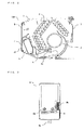
- Fig. 3 is a front view of the network repeater to be contained in the indoor unit of the air-conditioning apparatus according to Embodiment 1 of the present invention.
- the network repeater 9 As illustrated in Fig. 3 is contained.
- the network repeater 9 is connected to a control board 10, which will be described later, via a cable 9a and wirelessly communicates with a network such as LAN and WAN.
- a network such as LAN and WAN.
- the network repeater 9 performs Wi-Fi communication with the network such as LAN and WAN.
- a plurality of indication lamps 9b for indicating a communication state and an error state, for example, is provided on the network repeater 9.
- the network repeater 9 is also provided with a switch 9c for switching on and off of wireless communication and a switch 9d for enabling or disabling a remote operation, for example.
- Fig. 4 is a perspective view of the indoor unit of the air-conditioning apparatus according to Embodiment 1 of the present invention in a state in which the front panel is removed.
- Fig. 5 is a cross-sectional view of the indoor unit of the air-conditioning apparatus according to Embodiment 1 of the present invention at an opening formed on the wall of the housing.
- Fig. 6 is an exploded perspective view of the indoor unit of the air-conditioning apparatus according to Embodiment 1 of the present invention in a state in which the front panel and the wall of the housing are removed.
- the network repeater 9 is not shown.
- the opening 22 is formed on the wall 21 of the housing 7.
- the electrical component compartment member 6 On a rear side of the wall 21, the electrical component compartment member 6 is disposed.
- a network repeater compartment 31 having a box shape with a front side open is formed.
- the opening 22 is formed at a position faced with an opening of the network repeater compartment 31.
- the network repeater 9 is contained in a space 32 inside the network repeater compartment 31. Specifically, the opening 22 leads to a front end of the space 32 in which the network repeater 9 is contained.
- a control board compartment 33 having a box shape with a front side open is formed.
- the control board 10 is contained.
- the control board compartment 33 is covered with a control board compartment cover 34.
- the control board compartment cover 34 is capable of being removed.
- the cable 9a extending from the network repeater 9 can be connected to the control board 10. Removal of the wall 21 of the housing 7 and the control board compartment cover 34 of the electrical component compartment member 6 may or may not be capable of being performed by the user.
- a groove 31 a in which a front side is open is formed at a position close to the control board compartment 33 in a peripheral wall of the network repeater compartment 31 .
- the opening of the groove 31 a is covered with the wall 21 of the housing 7.
- a cable fixing member fixing portion 35 for attaching a cable fixing member 11 is formed at a position located between the network repeater compartment 31 and the control board compartment 33 of the electrical component compartment member 6.
- the cable fixing member 11 is a cable tie, and the cable fixing member fixing portion 35 is a hole, for example.
- a cable compartment space 36 is formed below the network repeater compartment 31 of the electrical component compartment member 6, a cable compartment space 36 is formed below the network repeater compartment 31 of the electrical component compartment member 6, a cable compartment space 36 is formed below the network repeater compartment 31 of the electrical component compartment member 6, a cable compartment space 36 is formed below the network repeater compartment 31 of the electrical component compartment member 6, a cable compartment space 36 is formed below the network repeater compartment 31 of the electrical component compartment member 6, a cable compartment space 36
- the cable 9a extending from the network repeater 9 is wired to pass inside the groove 31 a and to reach the cable compartment space 36. Moreover, a middle portion of the cable 9a is fixed by the cable fixing member 11 attached at the cable fixing member fixing portion 35. Moreover, a tip end of the cable 9a is connected to the control board 10. After a portion of the cable 9a between a section fixed by the cable fixing member 11 and the network repeater 9 is contained in the cable compartment space 36 in a state in which a sufficient extra length remains, the wall 21 of the housing 7 is installed.
- the cable 9a has a length sufficient for drawing out the network repeater 9 contained in the space 32 through the opening 22 formed in the wall 21 of the housing 7, and a portion of the cable 9a between the section fixed by the cable fixing member 11 and the network repeater 9 has a length sufficient for drawing out the network repeater 9 contained in the space 32 through the opening 22 formed in the wall 21 of the housing 7.
- the cable fixing member fixing portion 35 may be formed in the network repeater compartment 31.
- the cable fixing member 11 may fix a portion of the cable 9a between a section located inside the groove 31 a and the network repeater 9 and in such a case, it is only necessary that the cable compartment space 36 is formed inside the network repeater compartment 31.
- Fig. 9 is a perspective view of an essential part of the indoor unit of the air-conditioning apparatus according to Embodiment 1 of the present invention in a state in which the front panel is removed.
- a cutout 22a is formed in each of regions facing each other on a peripheral edge of the opening 22 in the wall 21 of the housing 7. Moreover, at a position corresponding to the cutout 22a on the peripheral wall of the network repeater compartment 31 of the electrical component compartment member 6, a stepped portion 31 b is formed. The user can put fingers into the cutouts 22a and the stepped portions 31 b and hold the network repeater 9.
- Fig. 9 illustrates a case in which the cutouts 22a and the stepped portions 31 b are formed in the vertical direction of the network repeater 9; however the configuration is not limited to this case.
- the cutout 22a and the stepped portion 31 b may be formed in the horizontal direction of the network repeater 9.
- the opening 22 leading to the front end of the space 32 in which the network repeater 9 for wirelessly communicating with the network is contained is formed, and the opening 22 is exposed in the state in which the front panel 8 is removed.
- the interior aesthetics can be improved by incorporating the network repeater 9 in the indoor unit 100 of the air-conditioning apparatus.
- the network repeater 9 incorporated in the indoor unit 100 of the air-conditioning apparatus can be taken out of the indoor unit 100 of the air-conditioning apparatus for visual check and operations as necessary, ensuring the functionality.
- the control board 10 and the network repeater 9 are connected by the cable 9a disposed on the rear side of the wall 21 of the housing 7, and the cable 9a has a length sufficient for drawing out the network repeater 9 contained in the space 32 through the opening 22.
- the network repeater 9 is to be taken out of the indoor unit 100 of the air-conditioning apparatus, removal of the cable 9a from the control board 10, application of a load to a connection portion of the cable 9a connected with the control board 10, and the like are suppressed, and usability for the user is improved.
- the middle portion of the cable 9a is fixed by the cable fixing member 11, and the portion of the cable 9a between the section fixed by the cable fixing member 11 and the network repeater 9 has a length sufficient for drawing out the network repeater 9 contained in the space 32 through the opening 22.
- the cutout 22a is formed in each of the regions facing each other on the peripheral edge of the opening 22.
- the network repeater 9 is contained in the space 32 in a state in which the surface on which the indication lamps 9b and the switches 9c and 9d are not disposed is located on the opening 22 side; however, the network repeater 9 may be contained in the space 32 in a state in which the surface on which the indication lamps 9b and the switches 9c and 9d are disposed is located on the opening 22 side.
- the visual check, the operation and the like can be performed without taking out the network repeater 9 from the indoor unit 100 of the air-conditioning apparatus and thus, the usability for the user is improved.
- the indication lamps 9b and the switches 9c and 9d are disposed on the front of the network repeater 9; however, the indication lamps 9b and the switches 9c and 9d may be disposed on a surface other than the front of the network repeater 9.
- the front panel 8 covers a whole front of the housing 7; however, the front panel 8 may cover a part of the housing 7 and it is only necessary that at least the region where the opening 22 of the wall 21 is formed is covered.
- the opening 22 formed in the wall 21 of the housing 7 is exposed by removing the front panel 8 is described; however, the opening 22 formed in the wall 21 of the housing 7 may be exposed by removing a part of the front panel 8, or the opening 22 formed in the wall 21 of the housing 7 may be exposed by automatically or manually opening of the whole or a part of the front panel 8.
Abstract
Description
- The present invention relates to an indoor unit of an air-conditioning apparatus.
- With spread of HEMS (Home Energy Management System), a smart grid, and other technologies, a demand for energy management of an air-conditioning apparatus has been increasing recently. Moreover, demands for central management control for managing the air-conditioning apparatus as well as other devices, remote operation for operating the air-conditioning apparatus from a remote location such as outside a house, and other conveniences have been increasing.
- To meet these demands, an indoor unit of an air-conditioning apparatus provided with a network repeater for wirelessly communicating with a network has been proposed. The network repeater is connected to a control board incorporated in the indoor unit of the air-conditioning apparatus. Signals used for energy management of the air-conditioning apparatus, central management control, remote operation or another use are transmitted to and received from the network via the network repeater. Typically, the network repeater is provided with an indication lamp for indicating a communication state, an error state or another state. Also, the network repeater is typically provided with switches for switching on and off of wireless communication, recovering from an error, and other operations. The network repeater is provided on a wall surface in the vicinity of the indoor unit of the air-conditioning apparatus, for example (see
Patent Literature 1, for example). -
- Patent Literature 1: Japanese Unexamined Patent Application Publication No.
2008-4975 Fig. 7 , etc.) - Some of the indication lamps provided on the network repeater may be normally lit or may flash, and when such a network repeater is installed in a conspicuous place, a user might feel uncomfortable. Moreover, since the network repeater itself is exposed, the user might feel that interior aesthetics of a room may be damaged. The network repeater can be incorporated in the indoor unit of the air-conditioning apparatus to improve the interior aesthetics. In such a case, however, the user can no longer visually check the communication state, the error state, and other states, or can no longer operate the switches, for example, and functionality is lowered. In other words, the conventional indoor unit of the air-conditioning apparatus cannot improve the interior aesthetics while ensuring the functionality.
- The present invention has been made in view of the aforementioned problems and is to obtain an indoor unit of an air-conditioning apparatus capable of improving the interior aesthetics while ensuring the functionality.
- An indoor unit of an air-conditioning apparatus according to the present invention includes a housing having a wall extending in a horizontal direction, and a front panel covering at least a part of a front side of the wall. An opening leading to a front end of a space in which a network repeater for wirelessly communicating with a network is to be contained is formed on a region of the wall covered by the front panel, and the opening is configured to be exposed in a state in which a whole or a part of the front panel is removed or opened.
- In the indoor unit of the air-conditioning apparatus according to the present invention, the opening leading to the front end of the space in which the network repeater for wirelessly communicating with the network is contained is formed on the region covered with the front panel of the wall of the housing, and the opening is exposed in the state in which the whole of or a part of the front panel is removed or open. Thus, the network repeater can be incorporated in the indoor unit of the air-conditioning apparatus to improve the interior aesthetics. Moreover, because the network repeater incorporated in the indoor unit of the air-conditioning apparatus can be taken out of the indoor unit of the air-conditioning apparatus and subjected to visual check and operations as necessary, the functionality can be ensured. Brief Description of Drawings
- [
Fig. 1] Fig. 1 is an exploded perspective view of an indoor unit of an air-conditioning apparatus according toEmbodiment 1 of the present invention. - [
Fig. 2] Fig. 2 is a cross-sectional view of the indoor unit of the air-conditioning apparatus according toEmbodiment 1 of the present invention. - [
Fig. 3] Fig. 3 is a front view of a network repeater to be contained in the indoor unit of the air-conditioning apparatus according toEmbodiment 1 of the present invention. - [
Fig. 4] Fig. 4 is a perspective view of the indoor unit of the air-conditioning apparatus according toEmbodiment 1 of the present invention in a state in which a front panel is removed. - [
Fig. 5] Fig. 5 is a cross-sectional view of the indoor unit of the air-conditioning apparatus according toEmbodiment 1 of the present invention at an opening formed on a wall of a housing. - [
Fig. 6] Fig. 6 is an exploded perspective view of the indoor unit of the air-conditioning apparatus according toEmbodiment 1 of the present invention in a state in which the front panel and the wall of the housing are removed. - [
Fig. 7] Fig. 7 is a perspective view of an essential part of the indoor unit of the air-conditioning apparatus according toEmbodiment 1 of the present invention in a state in which the front panel, the wall of the housing, and a control board compartment cover of an electrical component compartment member are removed. - [
Fig. 8] Fig. 8 is a perspective view of the essential part of the indoor unit of the air-conditioning apparatus according toEmbodiment 1 of the present invention in a state in which the front panel, the wall of the housing, and the control board compartment cover for the electrical component compartment member are removed. - [
Fig. 9] Fig. 9 is a perspective view of the essential part of the indoor unit of the air-conditioning apparatus according toEmbodiment 1 of the present invention in a state in which the front panel is removed. - An indoor unit of an air-conditioning apparatus according to the present invention will be described below by using the drawings.
- Configurations and other specifications described below are only an example, and the indoor unit of the air-conditioning apparatus according to the present invention is not limited to such configurations and other specifications. In each figure, reference signs are omitted as appropriate for duplicated or similar members or portions.
- An indoor unit of an air-conditioning apparatus according to
Embodiment 1 will be described. - A configuration of the indoor unit of the air-conditioning apparatus according to
Embodiment 1 will be described. -
Fig. 1 is an exploded perspective view of the indoor unit of the air-conditioning apparatus according toEmbodiment 1 of the present invention.Fig. 2 is a cross-sectional view of the indoor unit of the air-conditioning apparatus according toEmbodiment 1 of the present invention. - As illustrated in
Figs. 1 and2 , theindoor unit 100 of the air-conditioning apparatus includes abase 1, afan 2, aheat exchanger 3, adrain pan assembly 4, a filterautomatic cleaning unit 5, an electricalcomponent compartment member 6, ahousing 7, and a front panel 8 (design panel). Thedrain pan assembly 4 has a vertical winddirection adjustment plate 4a. - On the
base 1, thefan 2, theheat exchanger 3, and thedrain pan assembly 4 on which the electricalcomponent compartment member 6 is installed are installed. Moreover, on thebase 1, thehousing 7 on which the filterautomatic cleaning unit 5 is installed is installed by a screw or the like. Thehousing 7 has awall 21 extending in a horizontal direction. Thewall 21 can be removed from thehousing 7. Thefront panel 8 is installed on a front side of thehousing 7, and a front side of thewall 21 is covered by thefront panel 8. A user can attach and remove thefront panel 8. - When the
fan 2 is driven, an indoor air above theindoor unit 100 of the air-conditioning apparatus is suctioned through a filter installed on the filterautomatic cleaning unit 5, is changed to a cold air, a warm air or the like by heat exchange in theheat exchanger 3, and the cold air, the warm air or the like passes through the vertical winddirection adjustment plate 4a of thedrain pan assembly 4 and is blown out into a room. The vertical winddirection adjustment plate 4a rotationally moves, and adjusts a vertical wind direction of the air blown out of theindoor unit 100 of the air-conditioning apparatus. - A configuration of a network repeater contained in the indoor unit of the air-conditioning apparatus according to
Embodiment 1 will be described. -
Fig. 3 is a front view of the network repeater to be contained in the indoor unit of the air-conditioning apparatus according toEmbodiment 1 of the present invention. - In the
indoor unit 100 of the air-conditioning apparatus, thenetwork repeater 9 as illustrated inFig. 3 is contained. Thenetwork repeater 9 is connected to acontrol board 10, which will be described later, via acable 9a and wirelessly communicates with a network such as LAN and WAN. For example, thenetwork repeater 9 performs Wi-Fi communication with the network such as LAN and WAN. - On the
network repeater 9, a plurality ofindication lamps 9b for indicating a communication state and an error state, for example, is provided. Thenetwork repeater 9 is also provided with aswitch 9c for switching on and off of wireless communication and aswitch 9d for enabling or disabling a remote operation, for example. - A configuration of a compartment of the network repeater of the indoor unit of the air-conditioning apparatus according to
Embodiment 1 will be described. -
Fig. 4 is a perspective view of the indoor unit of the air-conditioning apparatus according toEmbodiment 1 of the present invention in a state in which the front panel is removed.Fig. 5 is a cross-sectional view of the indoor unit of the air-conditioning apparatus according toEmbodiment 1 of the present invention at an opening formed on the wall of the housing.Fig. 6 is an exploded perspective view of the indoor unit of the air-conditioning apparatus according toEmbodiment 1 of the present invention in a state in which the front panel and the wall of the housing are removed. InFigs. 4 and 5 , thenetwork repeater 9 is not shown. - As illustrated in
Figs. 4 to 6 , theopening 22 is formed on thewall 21 of thehousing 7. On a rear side of thewall 21, the electricalcomponent compartment member 6 is disposed. On the electricalcomponent compartment member 6, anetwork repeater compartment 31 having a box shape with a front side open is formed. Theopening 22 is formed at a position faced with an opening of thenetwork repeater compartment 31. Thenetwork repeater 9 is contained in aspace 32 inside thenetwork repeater compartment 31. Specifically, theopening 22 leads to a front end of thespace 32 in which thenetwork repeater 9 is contained. - Moreover, on the electrical
component compartment member 6, acontrol board compartment 33 having a box shape with a front side open is formed. In thecontrol board compartment 33, thecontrol board 10 is contained. Thecontrol board compartment 33 is covered with a controlboard compartment cover 34. The controlboard compartment cover 34 is capable of being removed. - In other words, by removing the
front panel 8, thewall 21 of thehousing 7, and the control board compartment cover 34 of the electricalcomponent compartment member 6 of theindoor unit 100 of the air-conditioning apparatus, thecable 9a extending from thenetwork repeater 9 can be connected to thecontrol board 10. Removal of thewall 21 of thehousing 7 and the control board compartment cover 34 of the electricalcomponent compartment member 6 may or may not be capable of being performed by the user. -
Figs. 7 and8 are perspective views of essential parts of the indoor unit of the air-conditioning apparatus according toEmbodiment 1 of the present invention in a state in which the front panel, the wall of the housing, and the control board compartment cover of the electrical component compartment member are removed.Fig. 7 illustrates a state before thecable 9a of thenetwork repeater 9 is wired, andFig. 8 illustrates a state after thecable 9a of thenetwork repeater 9 is wired. - As illustrated in
Figs. 7 and8 , at a position close to thecontrol board compartment 33 in a peripheral wall of thenetwork repeater compartment 31, agroove 31 a in which a front side is open is formed. The opening of thegroove 31 a is covered with thewall 21 of thehousing 7. Moreover, at a position located between thenetwork repeater compartment 31 and thecontrol board compartment 33 of the electricalcomponent compartment member 6, a cable fixingmember fixing portion 35 for attaching acable fixing member 11 is formed. Thecable fixing member 11 is a cable tie, and the cable fixingmember fixing portion 35 is a hole, for example. Moreover, below thenetwork repeater compartment 31 of the electricalcomponent compartment member 6, acable compartment space 36 is formed. - The
cable 9a extending from thenetwork repeater 9 is wired to pass inside thegroove 31 a and to reach thecable compartment space 36. Moreover, a middle portion of thecable 9a is fixed by thecable fixing member 11 attached at the cable fixingmember fixing portion 35. Moreover, a tip end of thecable 9a is connected to thecontrol board 10. After a portion of thecable 9a between a section fixed by thecable fixing member 11 and thenetwork repeater 9 is contained in thecable compartment space 36 in a state in which a sufficient extra length remains, thewall 21 of thehousing 7 is installed. In other words, thecable 9a has a length sufficient for drawing out thenetwork repeater 9 contained in thespace 32 through theopening 22 formed in thewall 21 of thehousing 7, and a portion of thecable 9a between the section fixed by thecable fixing member 11 and thenetwork repeater 9 has a length sufficient for drawing out thenetwork repeater 9 contained in thespace 32 through theopening 22 formed in thewall 21 of thehousing 7. - The cable fixing
member fixing portion 35 may be formed in thenetwork repeater compartment 31. In other words, thecable fixing member 11 may fix a portion of thecable 9a between a section located inside thegroove 31 a and thenetwork repeater 9 and in such a case, it is only necessary that thecable compartment space 36 is formed inside thenetwork repeater compartment 31. -
Fig. 9 is a perspective view of an essential part of the indoor unit of the air-conditioning apparatus according toEmbodiment 1 of the present invention in a state in which the front panel is removed. - As illustrated in
Fig. 9 , acutout 22a is formed in each of regions facing each other on a peripheral edge of theopening 22 in thewall 21 of thehousing 7. Moreover, at a position corresponding to thecutout 22a on the peripheral wall of thenetwork repeater compartment 31 of the electricalcomponent compartment member 6, a steppedportion 31 b is formed. The user can put fingers into thecutouts 22a and the steppedportions 31 b and hold thenetwork repeater 9.Fig. 9 illustrates a case in which thecutouts 22a and the steppedportions 31 b are formed in the vertical direction of thenetwork repeater 9; however the configuration is not limited to this case. For example, thecutout 22a and the steppedportion 31 b may be formed in the horizontal direction of thenetwork repeater 9. - An action of the indoor unit of the air-conditioning apparatus according to
Embodiment 1 will be described. - In the
indoor unit 100 of the air-conditioning apparatus, in the region covered with thefront panel 8 of thewall 21 of thehousing 7, theopening 22 leading to the front end of thespace 32 in which thenetwork repeater 9 for wirelessly communicating with the network is contained is formed, and theopening 22 is exposed in the state in which thefront panel 8 is removed. Thus, the interior aesthetics can be improved by incorporating thenetwork repeater 9 in theindoor unit 100 of the air-conditioning apparatus. Moreover, thenetwork repeater 9 incorporated in theindoor unit 100 of the air-conditioning apparatus can be taken out of theindoor unit 100 of the air-conditioning apparatus for visual check and operations as necessary, ensuring the functionality. - Moreover, in the
indoor unit 100 of the air-conditioning apparatus, thecontrol board 10 and thenetwork repeater 9 are connected by thecable 9a disposed on the rear side of thewall 21 of thehousing 7, and thecable 9a has a length sufficient for drawing out thenetwork repeater 9 contained in thespace 32 through theopening 22. Thus, when thenetwork repeater 9 is to be taken out of theindoor unit 100 of the air-conditioning apparatus, removal of thecable 9a from thecontrol board 10, application of a load to a connection portion of thecable 9a connected with thecontrol board 10, and the like are suppressed, and usability for the user is improved. - Moreover, in the
indoor unit 100 of the air-conditioning apparatus, the middle portion of thecable 9a is fixed by thecable fixing member 11, and the portion of thecable 9a between the section fixed by thecable fixing member 11 and thenetwork repeater 9 has a length sufficient for drawing out thenetwork repeater 9 contained in thespace 32 through theopening 22. Thus, when thenetwork repeater 9 is to be taken out of theindoor unit 100 of the air-conditioning apparatus, the removal of thecable 9a from thecontrol board 10, the application of a load to a connection portion of thecable 9a connecting with thecontrol board 10, and the like are further suppressed, and the usability for the user is further improved. - Moreover, in the
indoor unit 100 of the air-conditioning apparatus, thecutout 22a is formed in each of the regions facing each other on the peripheral edge of theopening 22. Thus, when thenetwork repeater 9 is to be taken out of theindoor unit 100 of the air-conditioning apparatus, thenetwork repeater 9 can be held by the fingers, and the usability for the user is improved. - The above describes a case in which the
network repeater 9 is contained in thespace 32 in a state in which the surface on which theindication lamps 9b and theswitches opening 22 side; however, thenetwork repeater 9 may be contained in thespace 32 in a state in which the surface on which theindication lamps 9b and theswitches opening 22 side. In such a case, the visual check, the operation and the like can be performed without taking out thenetwork repeater 9 from theindoor unit 100 of the air-conditioning apparatus and thus, the usability for the user is improved. Moreover, a case in which theindication lamps 9b and theswitches network repeater 9 is described; however, theindication lamps 9b and theswitches network repeater 9. - The above describes a case in which the
front panel 8 covers a whole front of thehousing 7; however, thefront panel 8 may cover a part of thehousing 7 and it is only necessary that at least the region where theopening 22 of thewall 21 is formed is covered. Moreover, a case in which theopening 22 formed in thewall 21 of thehousing 7 is exposed by removing thefront panel 8 is described; however, theopening 22 formed in thewall 21 of thehousing 7 may be exposed by removing a part of thefront panel 8, or theopening 22 formed in thewall 21 of thehousing 7 may be exposed by automatically or manually opening of the whole or a part of thefront panel 8. - 1
base 2fan 3 heat exchanger4drain pan assembly 4a vertical winddirection adjustment plate 5 filterautomatic cleaning unit 6 electricalcomponent compartment member 7housing 8front panel 9network repeater 9a cable9b indication lamp 9d switch 10control board 11cable fixing member 21wall 22opening 22a cutout31network repeater compartment 31 agroove 31 b steppedportion 32space 33 control board compartment34 controlboard compartment cover 35 cable fixingmember fixing portion 36cable compartment space 100 indoor unit of air-conditioning apparatus
Claims (6)
- An indoor unit (100) of an air-conditioning apparatus comprising:a housing (7) having a wall (21) extending in a horizontal direction; anda front panel (8) covering at least a part of a front side of the wall (21), whereinon a region of the wall (21) covered by the front panel (8), an opening (22) leading to a front end of a space (32) in which a network repeater (9) for wirelessly communicating with a network is to be contained is formed, the opening (22) being configured to be exposed in a state in which a whole or a part of the front panel (8) is removed or opened.
- The indoor unit (100) of the air-conditioning apparatus of claim 1, further comprising a control board (10), and the network repeater (9) contained in the space (32) and configured to relay the control board (10) and the network.
- The indoor unit (100) of the air-conditioning apparatus of claim 2, wherein
the control board (10) and the network repeater (9) are connected by a cable (9a) disposed on a rear side of the wall (21), and
the cable (9a) has a length sufficient for drawing out the network repeater (9) contained in the space (32) through the opening (22). - The indoor unit (100) of the air-conditioning apparatus of claim 3, wherein
a middle portion of the cable (9a) is fixed by a cable fixing member (11), and
a portion of the cable (9a) between the middle portion and the network repeater (9) has a length sufficient for drawing out the network repeater (9) contained in the space (32) through the opening (22). - The indoor unit (100) of the air-conditioning apparatus of any one of claims 1 to 4, wherein a cutout (22a) is formed in each of regions facing each other on a peripheral edge of the opening (22).
- The indoor unit (100) of the air-conditioning apparatus of any one of claims 1 to 5, wherein the network repeater (9) performs Wi-Fi communication with the network.
Applications Claiming Priority (1)
| Application Number | Priority Date | Filing Date | Title |
|---|---|---|---|
| JP2014160039A JP6270658B2 (en) | 2014-08-06 | 2014-08-06 | Air conditioner indoor unit |
Publications (2)
| Publication Number | Publication Date |
|---|---|
| EP2982910A1 true EP2982910A1 (en) | 2016-02-10 |
| EP2982910B1 EP2982910B1 (en) | 2020-04-22 |
Family
ID=53794066
Family Applications (1)
| Application Number | Title | Priority Date | Filing Date |
|---|---|---|---|
| EP15179383.3A Active EP2982910B1 (en) | 2014-08-06 | 2015-07-31 | Indoor unit of air-conditioning apparatus |
Country Status (4)
| Country | Link |
|---|---|
| US (1) | US9523511B2 (en) |
| EP (1) | EP2982910B1 (en) |
| JP (1) | JP6270658B2 (en) |
| CN (2) | CN105371360B (en) |
Families Citing this family (6)
| Publication number | Priority date | Publication date | Assignee | Title |
|---|---|---|---|---|
| JP6270658B2 (en) * | 2014-08-06 | 2018-01-31 | 三菱電機株式会社 | Air conditioner indoor unit |
| WO2017033258A1 (en) * | 2015-08-24 | 2017-03-02 | 三菱電機株式会社 | Indoor unit of air-conditioner |
| DE112019006774T5 (en) * | 2019-01-30 | 2021-10-14 | Mitsubishi Electric Corporation | Indoor unit of an air conditioner |
| CN110730393B (en) * | 2019-10-24 | 2021-11-19 | 上海豪锦通信科技有限公司 | Network communication base station repeater |
| JP7310596B2 (en) | 2019-12-25 | 2023-07-19 | 株式会社富士通ゼネラル | Ceiling-mounted air conditioner |
| WO2021191940A1 (en) * | 2020-03-23 | 2021-09-30 | 三菱電機株式会社 | Indoor unit for air conditioner |
Citations (5)
| Publication number | Priority date | Publication date | Assignee | Title |
|---|---|---|---|---|
| EP1533576A2 (en) * | 2003-11-24 | 2005-05-25 | Lg Electronics Inc. | Air conditioner having an enhanced user perception |
| JP2008004975A (en) | 2006-06-20 | 2008-01-10 | Mitsubishi Electric Corp | Information terminal and home network system |
| US20110112692A1 (en) * | 2009-11-10 | 2011-05-12 | Jetlun Corporation | System for remote control of packaged terminal air conditioner and heaters with wireless remote control systems |
| EP2538147A2 (en) * | 2011-06-20 | 2012-12-26 | Mitsubishi Electric Corporation | Air-conditioning apparatus and support system of the same |
| WO2014020880A1 (en) * | 2012-07-30 | 2014-02-06 | パナソニック株式会社 | Operation system for home electric appliances and program for operating home electric appliances |
Family Cites Families (32)
| Publication number | Priority date | Publication date | Assignee | Title |
|---|---|---|---|---|
| TW299019U (en) * | 1995-03-07 | 1997-02-21 | Tokyo Shibaura Electric Co | Indoor units of airconditioner |
| US6058712A (en) * | 1996-07-12 | 2000-05-09 | Thermotek, Inc. | Hybrid air conditioning system and a method therefor |
| JPH11148676A (en) * | 1997-11-20 | 1999-06-02 | Fujitsu General Ltd | Light receiving unit for air conditioner |
| ES2258077T3 (en) * | 2000-04-10 | 2006-08-16 | Zensys A/S | DOMESTIC AUTOMATION SYSTEM FOR RF THAT INCLUDES CONTROLLERS WITH DUAL FUNCTIONALITY. |
| US6622925B2 (en) * | 2001-10-05 | 2003-09-23 | Enernet Corporation | Apparatus and method for wireless control |
| JP2003309883A (en) * | 2002-04-18 | 2003-10-31 | Hitachi Ltd | Control system and method |
| JP2005248735A (en) * | 2004-03-01 | 2005-09-15 | Toshiba Home Technology Corp | Electric fan |
| JP2006234280A (en) * | 2005-02-24 | 2006-09-07 | Sharp Corp | Air conditioner |
| US7434744B2 (en) * | 2005-12-12 | 2008-10-14 | Emerson Electric Co. | Low voltage power line communication for climate control system |
| JP2008111614A (en) * | 2006-10-31 | 2008-05-15 | Fujitsu General Ltd | Air conditioner |
| WO2008156782A2 (en) * | 2007-06-19 | 2008-12-24 | Sand Holdings, Llc | Devices and methods for automatic reset of monitored network network equipment |
| JP4589371B2 (en) * | 2007-10-05 | 2010-12-01 | 三菱電機株式会社 | Air conditioner |
| US7975495B2 (en) * | 2008-11-06 | 2011-07-12 | Trane International Inc. | Control scheme for coordinating variable capacity components of a refrigerant system |
| KR101116458B1 (en) * | 2009-01-21 | 2012-03-07 | 파나소닉 전공 주식회사 | Monitoring and control device |
| CN102575881B (en) * | 2009-10-22 | 2014-11-19 | 三菱电机株式会社 | Air conditioning device |
| US8724639B2 (en) * | 2010-02-26 | 2014-05-13 | Mohamed K. Mahmoud | Smart home hub |
| CN102725767B (en) * | 2010-11-30 | 2016-01-20 | 松下电器(美国)知识产权公司 | Communicator and communication means |
| KR101795025B1 (en) * | 2011-01-24 | 2017-11-07 | 엘지전자 주식회사 | A network system and a control method the same |
| US8660708B2 (en) * | 2011-06-02 | 2014-02-25 | Pvt Solar, Inc. | Method and system for healthy home zoning control configured for efficient energy use and conservation of energy resources |
| US9574815B2 (en) * | 2011-06-09 | 2017-02-21 | Mitsubishi Electric Corporation | Air-conditioning-apparatus indoor unit |
| US8478450B2 (en) * | 2011-10-04 | 2013-07-02 | Advanergy, Inc. | Power control system and method |
| JP5676499B2 (en) * | 2012-01-25 | 2015-02-25 | 株式会社オプティム | Information processing apparatus for controlling electrical appliances, program execution method, and program |
| JP5891383B2 (en) * | 2012-03-09 | 2016-03-23 | パナソニックIpマネジメント株式会社 | COMMUNICATION METHOD, COMPUTER PROGRAM, MOBILE TERMINAL, HOME ELECTRIC DEVICE, AND OPERATION SETTING SYSTEM FOR HOME ELECTRIC DEVICE |
| EP2884194B1 (en) * | 2012-08-08 | 2018-12-26 | Panasonic Intellectual Property Management Co., Ltd. | Household electrical appliance and household electrical system |
| JPWO2014024444A1 (en) * | 2012-08-08 | 2016-07-25 | パナソニックIpマネジメント株式会社 | Home appliance, home appliance system and server device |
| EP2963358B1 (en) * | 2013-02-25 | 2023-03-08 | Mitsubishi Electric Corporation | Air conditioner |
| MY173173A (en) * | 2013-04-18 | 2020-01-02 | Panasonic Ip Corp America | Data provision method using air conditioner log information |
| US20150059389A1 (en) * | 2013-09-05 | 2015-03-05 | Trane International Inc. | System and apparatus for heating or cooling having fluid cooled electronics |
| JP6021768B2 (en) * | 2013-09-09 | 2016-11-09 | 三菱電機株式会社 | Air conditioning system |
| JP2015088822A (en) * | 2013-10-29 | 2015-05-07 | 東芝ライテック株式会社 | Communication device, communication method, and communication system |
| JP6365080B2 (en) * | 2014-08-01 | 2018-08-01 | 三菱電機株式会社 | Air conditioner indoor unit |
| JP6270658B2 (en) * | 2014-08-06 | 2018-01-31 | 三菱電機株式会社 | Air conditioner indoor unit |
-
2014
- 2014-08-06 JP JP2014160039A patent/JP6270658B2/en active Active
-
2015
- 2015-07-30 US US14/813,194 patent/US9523511B2/en active Active
- 2015-07-31 EP EP15179383.3A patent/EP2982910B1/en active Active
- 2015-08-04 CN CN201510471577.5A patent/CN105371360B/en active Active
- 2015-08-04 CN CN201520580127.5U patent/CN204901970U/en active Active
Patent Citations (5)
| Publication number | Priority date | Publication date | Assignee | Title |
|---|---|---|---|---|
| EP1533576A2 (en) * | 2003-11-24 | 2005-05-25 | Lg Electronics Inc. | Air conditioner having an enhanced user perception |
| JP2008004975A (en) | 2006-06-20 | 2008-01-10 | Mitsubishi Electric Corp | Information terminal and home network system |
| US20110112692A1 (en) * | 2009-11-10 | 2011-05-12 | Jetlun Corporation | System for remote control of packaged terminal air conditioner and heaters with wireless remote control systems |
| EP2538147A2 (en) * | 2011-06-20 | 2012-12-26 | Mitsubishi Electric Corporation | Air-conditioning apparatus and support system of the same |
| WO2014020880A1 (en) * | 2012-07-30 | 2014-02-06 | パナソニック株式会社 | Operation system for home electric appliances and program for operating home electric appliances |
Also Published As
| Publication number | Publication date |
|---|---|
| US9523511B2 (en) | 2016-12-20 |
| CN204901970U (en) | 2015-12-23 |
| CN105371360B (en) | 2018-08-28 |
| CN105371360A (en) | 2016-03-02 |
| JP2016038125A (en) | 2016-03-22 |
| US20160040901A1 (en) | 2016-02-11 |
| JP6270658B2 (en) | 2018-01-31 |
| EP2982910B1 (en) | 2020-04-22 |
Similar Documents
| Publication | Publication Date | Title |
|---|---|---|
| US9523511B2 (en) | Indoor unit of air-conditioning apparatus | |
| CN102282735B (en) | Add-on device for a network device | |
| CN205535405U (en) | Compact lamp dish convenient to installation | |
| JP2017069851A (en) | Ic cartridge and environmental adjustment device | |
| JP2013066285A (en) | Box for housing electric apparatus | |
| CN112242716A (en) | Modular micro-grid central controller | |
| EP1865277A2 (en) | Refrigerator with an electronic panel support | |
| JP6173269B2 (en) | Communication equipment and air conditioner | |
| CN104456765A (en) | Air conditioner outdoor unit | |
| KR101570982B1 (en) | Safty device for distributing board | |
| CN211451247U (en) | Cooling fan | |
| CN209659769U (en) | A kind of intelligent domestic intelligence parlor electrical bus controls box | |
| CN208238152U (en) | Electrical appliance kit mounting rack, electric appliance case assembly and air conditioner indoor unit | |
| CN202710099U (en) | Embedded detector | |
| JP6201873B2 (en) | Communication control device | |
| CN209169720U (en) | It is a kind of to be mounted on outdoor and excellent waterproof effect distribution box | |
| CN108131725B (en) | Shell assembly of air conditioner and air conditioner with shell assembly | |
| JP6358559B2 (en) | Electrical equipment | |
| CN111174356A (en) | Cooling fan | |
| CN110098573A (en) | A kind of distribution box ancillary equipment | |
| KR102606077B1 (en) | Ventilator with detachable battery pack | |
| CN210744572U (en) | Intelligent monitoring equipment for electricity safety | |
| CN217116117U (en) | Novel intelligent gateway | |
| JP5942440B2 (en) | Air conditioner | |
| CN105546434A (en) | Integrated lamp panel convenient to install |
Legal Events
| Date | Code | Title | Description |
|---|---|---|---|
| PUAI | Public reference made under article 153(3) epc to a published international application that has entered the european phase |
Free format text: ORIGINAL CODE: 0009012 |
|
| AK | Designated contracting states |
Kind code of ref document: A1 Designated state(s): AL AT BE BG CH CY CZ DE DK EE ES FI FR GB GR HR HU IE IS IT LI LT LU LV MC MK MT NL NO PL PT RO RS SE SI SK SM TR |
|
| AX | Request for extension of the european patent |
Extension state: BA ME |
|
| 17P | Request for examination filed |
Effective date: 20160406 |
|
| RBV | Designated contracting states (corrected) |
Designated state(s): AL AT BE BG CH CY CZ DE DK EE ES FI FR GB GR HR HU IE IS IT LI LT LU LV MC MK MT NL NO PL PT RO RS SE SI SK SM TR |
|
| REG | Reference to a national code |
Ref country code: DE Ref legal event code: R079 Ref document number: 602015051014 Country of ref document: DE Free format text: PREVIOUS MAIN CLASS: F24F0011000000 Ipc: F24F0001000700 |
|
| GRAP | Despatch of communication of intention to grant a patent |
Free format text: ORIGINAL CODE: EPIDOSNIGR1 |
|
| STAA | Information on the status of an ep patent application or granted ep patent |
Free format text: STATUS: GRANT OF PATENT IS INTENDED |
|
| RIC1 | Information provided on ipc code assigned before grant |
Ipc: F24F 11/30 20180101ALI20191031BHEP Ipc: F24F 1/0007 20190101AFI20191031BHEP Ipc: F24F 11/62 20180101ALI20191031BHEP |
|
| INTG | Intention to grant announced |
Effective date: 20191202 |
|
| GRAS | Grant fee paid |
Free format text: ORIGINAL CODE: EPIDOSNIGR3 |
|
| GRAA | (expected) grant |
Free format text: ORIGINAL CODE: 0009210 |
|
| STAA | Information on the status of an ep patent application or granted ep patent |
Free format text: STATUS: THE PATENT HAS BEEN GRANTED |
|
| AK | Designated contracting states |
Kind code of ref document: B1 Designated state(s): AL AT BE BG CH CY CZ DE DK EE ES FI FR GB GR HR HU IE IS IT LI LT LU LV MC MK MT NL NO PL PT RO RS SE SI SK SM TR |
|
| REG | Reference to a national code |
Ref country code: CH Ref legal event code: EP |
|
| REG | Reference to a national code |
Ref country code: IE Ref legal event code: FG4D |
|
| REG | Reference to a national code |
Ref country code: DE Ref legal event code: R096 Ref document number: 602015051014 Country of ref document: DE |
|
| REG | Reference to a national code |
Ref country code: AT Ref legal event code: REF Ref document number: 1260626 Country of ref document: AT Kind code of ref document: T Effective date: 20200515 |
|
| REG | Reference to a national code |
Ref country code: LT Ref legal event code: MG4D |
|
| REG | Reference to a national code |
Ref country code: NL Ref legal event code: MP Effective date: 20200422 |
|
| PG25 | Lapsed in a contracting state [announced via postgrant information from national office to epo] |
Ref country code: GR Free format text: LAPSE BECAUSE OF FAILURE TO SUBMIT A TRANSLATION OF THE DESCRIPTION OR TO PAY THE FEE WITHIN THE PRESCRIBED TIME-LIMIT Effective date: 20200723 Ref country code: NO Free format text: LAPSE BECAUSE OF FAILURE TO SUBMIT A TRANSLATION OF THE DESCRIPTION OR TO PAY THE FEE WITHIN THE PRESCRIBED TIME-LIMIT Effective date: 20200722 Ref country code: LT Free format text: LAPSE BECAUSE OF FAILURE TO SUBMIT A TRANSLATION OF THE DESCRIPTION OR TO PAY THE FEE WITHIN THE PRESCRIBED TIME-LIMIT Effective date: 20200422 Ref country code: NL Free format text: LAPSE BECAUSE OF FAILURE TO SUBMIT A TRANSLATION OF THE DESCRIPTION OR TO PAY THE FEE WITHIN THE PRESCRIBED TIME-LIMIT Effective date: 20200422 Ref country code: SE Free format text: LAPSE BECAUSE OF FAILURE TO SUBMIT A TRANSLATION OF THE DESCRIPTION OR TO PAY THE FEE WITHIN THE PRESCRIBED TIME-LIMIT Effective date: 20200422 Ref country code: PT Free format text: LAPSE BECAUSE OF FAILURE TO SUBMIT A TRANSLATION OF THE DESCRIPTION OR TO PAY THE FEE WITHIN THE PRESCRIBED TIME-LIMIT Effective date: 20200824 Ref country code: FI Free format text: LAPSE BECAUSE OF FAILURE TO SUBMIT A TRANSLATION OF THE DESCRIPTION OR TO PAY THE FEE WITHIN THE PRESCRIBED TIME-LIMIT Effective date: 20200422 Ref country code: IS Free format text: LAPSE BECAUSE OF FAILURE TO SUBMIT A TRANSLATION OF THE DESCRIPTION OR TO PAY THE FEE WITHIN THE PRESCRIBED TIME-LIMIT Effective date: 20200822 |
|
| REG | Reference to a national code |
Ref country code: AT Ref legal event code: MK05 Ref document number: 1260626 Country of ref document: AT Kind code of ref document: T Effective date: 20200422 |
|
| PG25 | Lapsed in a contracting state [announced via postgrant information from national office to epo] |
Ref country code: HR Free format text: LAPSE BECAUSE OF FAILURE TO SUBMIT A TRANSLATION OF THE DESCRIPTION OR TO PAY THE FEE WITHIN THE PRESCRIBED TIME-LIMIT Effective date: 20200422 Ref country code: LV Free format text: LAPSE BECAUSE OF FAILURE TO SUBMIT A TRANSLATION OF THE DESCRIPTION OR TO PAY THE FEE WITHIN THE PRESCRIBED TIME-LIMIT Effective date: 20200422 Ref country code: RS Free format text: LAPSE BECAUSE OF FAILURE TO SUBMIT A TRANSLATION OF THE DESCRIPTION OR TO PAY THE FEE WITHIN THE PRESCRIBED TIME-LIMIT Effective date: 20200422 Ref country code: BG Free format text: LAPSE BECAUSE OF FAILURE TO SUBMIT A TRANSLATION OF THE DESCRIPTION OR TO PAY THE FEE WITHIN THE PRESCRIBED TIME-LIMIT Effective date: 20200722 |
|
| PG25 | Lapsed in a contracting state [announced via postgrant information from national office to epo] |
Ref country code: AL Free format text: LAPSE BECAUSE OF FAILURE TO SUBMIT A TRANSLATION OF THE DESCRIPTION OR TO PAY THE FEE WITHIN THE PRESCRIBED TIME-LIMIT Effective date: 20200422 |
|
| REG | Reference to a national code |
Ref country code: DE Ref legal event code: R097 Ref document number: 602015051014 Country of ref document: DE |
|
| PG25 | Lapsed in a contracting state [announced via postgrant information from national office to epo] |
Ref country code: CZ Free format text: LAPSE BECAUSE OF FAILURE TO SUBMIT A TRANSLATION OF THE DESCRIPTION OR TO PAY THE FEE WITHIN THE PRESCRIBED TIME-LIMIT Effective date: 20200422 Ref country code: RO Free format text: LAPSE BECAUSE OF FAILURE TO SUBMIT A TRANSLATION OF THE DESCRIPTION OR TO PAY THE FEE WITHIN THE PRESCRIBED TIME-LIMIT Effective date: 20200422 Ref country code: EE Free format text: LAPSE BECAUSE OF FAILURE TO SUBMIT A TRANSLATION OF THE DESCRIPTION OR TO PAY THE FEE WITHIN THE PRESCRIBED TIME-LIMIT Effective date: 20200422 Ref country code: SM Free format text: LAPSE BECAUSE OF FAILURE TO SUBMIT A TRANSLATION OF THE DESCRIPTION OR TO PAY THE FEE WITHIN THE PRESCRIBED TIME-LIMIT Effective date: 20200422 Ref country code: ES Free format text: LAPSE BECAUSE OF FAILURE TO SUBMIT A TRANSLATION OF THE DESCRIPTION OR TO PAY THE FEE WITHIN THE PRESCRIBED TIME-LIMIT Effective date: 20200422 Ref country code: DK Free format text: LAPSE BECAUSE OF FAILURE TO SUBMIT A TRANSLATION OF THE DESCRIPTION OR TO PAY THE FEE WITHIN THE PRESCRIBED TIME-LIMIT Effective date: 20200422 Ref country code: AT Free format text: LAPSE BECAUSE OF FAILURE TO SUBMIT A TRANSLATION OF THE DESCRIPTION OR TO PAY THE FEE WITHIN THE PRESCRIBED TIME-LIMIT Effective date: 20200422 |
|
| PG25 | Lapsed in a contracting state [announced via postgrant information from national office to epo] |
Ref country code: PL Free format text: LAPSE BECAUSE OF FAILURE TO SUBMIT A TRANSLATION OF THE DESCRIPTION OR TO PAY THE FEE WITHIN THE PRESCRIBED TIME-LIMIT Effective date: 20200422 Ref country code: SK Free format text: LAPSE BECAUSE OF FAILURE TO SUBMIT A TRANSLATION OF THE DESCRIPTION OR TO PAY THE FEE WITHIN THE PRESCRIBED TIME-LIMIT Effective date: 20200422 Ref country code: MC Free format text: LAPSE BECAUSE OF FAILURE TO SUBMIT A TRANSLATION OF THE DESCRIPTION OR TO PAY THE FEE WITHIN THE PRESCRIBED TIME-LIMIT Effective date: 20200422 |
|
| PLBE | No opposition filed within time limit |
Free format text: ORIGINAL CODE: 0009261 |
|
| REG | Reference to a national code |
Ref country code: CH Ref legal event code: PL |
|
| STAA | Information on the status of an ep patent application or granted ep patent |
Free format text: STATUS: NO OPPOSITION FILED WITHIN TIME LIMIT |
|
| 26N | No opposition filed |
Effective date: 20210125 |
|
| GBPC | Gb: european patent ceased through non-payment of renewal fee |
Effective date: 20200731 |
|
| REG | Reference to a national code |
Ref country code: BE Ref legal event code: MM Effective date: 20200731 |
|
| PG25 | Lapsed in a contracting state [announced via postgrant information from national office to epo] |
Ref country code: LI Free format text: LAPSE BECAUSE OF NON-PAYMENT OF DUE FEES Effective date: 20200731 Ref country code: LU Free format text: LAPSE BECAUSE OF NON-PAYMENT OF DUE FEES Effective date: 20200731 Ref country code: FR Free format text: LAPSE BECAUSE OF NON-PAYMENT OF DUE FEES Effective date: 20200731 Ref country code: GB Free format text: LAPSE BECAUSE OF NON-PAYMENT OF DUE FEES Effective date: 20200731 Ref country code: CH Free format text: LAPSE BECAUSE OF NON-PAYMENT OF DUE FEES Effective date: 20200731 |
|
| PG25 | Lapsed in a contracting state [announced via postgrant information from national office to epo] |
Ref country code: BE Free format text: LAPSE BECAUSE OF NON-PAYMENT OF DUE FEES Effective date: 20200731 Ref country code: SI Free format text: LAPSE BECAUSE OF FAILURE TO SUBMIT A TRANSLATION OF THE DESCRIPTION OR TO PAY THE FEE WITHIN THE PRESCRIBED TIME-LIMIT Effective date: 20200422 |
|
| PG25 | Lapsed in a contracting state [announced via postgrant information from national office to epo] |
Ref country code: IE Free format text: LAPSE BECAUSE OF NON-PAYMENT OF DUE FEES Effective date: 20200731 |
|
| PG25 | Lapsed in a contracting state [announced via postgrant information from national office to epo] |
Ref country code: TR Free format text: LAPSE BECAUSE OF FAILURE TO SUBMIT A TRANSLATION OF THE DESCRIPTION OR TO PAY THE FEE WITHIN THE PRESCRIBED TIME-LIMIT Effective date: 20200422 Ref country code: MT Free format text: LAPSE BECAUSE OF FAILURE TO SUBMIT A TRANSLATION OF THE DESCRIPTION OR TO PAY THE FEE WITHIN THE PRESCRIBED TIME-LIMIT Effective date: 20200422 Ref country code: CY Free format text: LAPSE BECAUSE OF FAILURE TO SUBMIT A TRANSLATION OF THE DESCRIPTION OR TO PAY THE FEE WITHIN THE PRESCRIBED TIME-LIMIT Effective date: 20200422 |
|
| PG25 | Lapsed in a contracting state [announced via postgrant information from national office to epo] |
Ref country code: MK Free format text: LAPSE BECAUSE OF FAILURE TO SUBMIT A TRANSLATION OF THE DESCRIPTION OR TO PAY THE FEE WITHIN THE PRESCRIBED TIME-LIMIT Effective date: 20200422 |
|
| P01 | Opt-out of the competence of the unified patent court (upc) registered |
Effective date: 20230512 |
|
| PGFP | Annual fee paid to national office [announced via postgrant information from national office to epo] |
Ref country code: IT Payment date: 20230612 Year of fee payment: 9 |
|
| PGFP | Annual fee paid to national office [announced via postgrant information from national office to epo] |
Ref country code: DE Payment date: 20230607 Year of fee payment: 9 |