EP2982839B1 - Reductant tank sensor diagnostic method and system - Google Patents
Reductant tank sensor diagnostic method and system Download PDFInfo
- Publication number
- EP2982839B1 EP2982839B1 EP14180096.1A EP14180096A EP2982839B1 EP 2982839 B1 EP2982839 B1 EP 2982839B1 EP 14180096 A EP14180096 A EP 14180096A EP 2982839 B1 EP2982839 B1 EP 2982839B1
- Authority
- EP
- European Patent Office
- Prior art keywords
- sensor
- value
- reductant
- tank
- dosing
- Prior art date
- Legal status (The legal status is an assumption and is not a legal conclusion. Google has not performed a legal analysis and makes no representation as to the accuracy of the status listed.)
- Active
Links
Images


Classifications
-
- F—MECHANICAL ENGINEERING; LIGHTING; HEATING; WEAPONS; BLASTING
- F01—MACHINES OR ENGINES IN GENERAL; ENGINE PLANTS IN GENERAL; STEAM ENGINES
- F01N—GAS-FLOW SILENCERS OR EXHAUST APPARATUS FOR MACHINES OR ENGINES IN GENERAL; GAS-FLOW SILENCERS OR EXHAUST APPARATUS FOR INTERNAL-COMBUSTION ENGINES
- F01N11/00—Monitoring or diagnostic devices for exhaust-gas treatment apparatus
-
- F—MECHANICAL ENGINEERING; LIGHTING; HEATING; WEAPONS; BLASTING
- F01—MACHINES OR ENGINES IN GENERAL; ENGINE PLANTS IN GENERAL; STEAM ENGINES
- F01N—GAS-FLOW SILENCERS OR EXHAUST APPARATUS FOR MACHINES OR ENGINES IN GENERAL; GAS-FLOW SILENCERS OR EXHAUST APPARATUS FOR INTERNAL-COMBUSTION ENGINES
- F01N3/00—Exhaust or silencing apparatus having means for purifying, rendering innocuous, or otherwise treating exhaust
- F01N3/08—Exhaust or silencing apparatus having means for purifying, rendering innocuous, or otherwise treating exhaust for rendering innocuous
- F01N3/10—Exhaust or silencing apparatus having means for purifying, rendering innocuous, or otherwise treating exhaust for rendering innocuous by thermal or catalytic conversion of noxious components of exhaust
- F01N3/18—Exhaust or silencing apparatus having means for purifying, rendering innocuous, or otherwise treating exhaust for rendering innocuous by thermal or catalytic conversion of noxious components of exhaust characterised by methods of operation; Control
- F01N3/20—Exhaust or silencing apparatus having means for purifying, rendering innocuous, or otherwise treating exhaust for rendering innocuous by thermal or catalytic conversion of noxious components of exhaust characterised by methods of operation; Control specially adapted for catalytic conversion
- F01N3/206—Adding periodically or continuously substances to exhaust gases for promoting purification, e.g. catalytic material in liquid form, NOx reducing agents
- F01N3/208—Control of selective catalytic reduction [SCR], e.g. by adjusting the dosing of reducing agent
-
- F—MECHANICAL ENGINEERING; LIGHTING; HEATING; WEAPONS; BLASTING
- F02—COMBUSTION ENGINES; HOT-GAS OR COMBUSTION-PRODUCT ENGINE PLANTS
- F02B—INTERNAL-COMBUSTION PISTON ENGINES; COMBUSTION ENGINES IN GENERAL
- F02B77/00—Component parts, details or accessories, not otherwise provided for
- F02B77/08—Safety, indicating, or supervising devices
- F02B77/083—Safety, indicating, or supervising devices relating to maintenance, e.g. diagnostic device
-
- F—MECHANICAL ENGINEERING; LIGHTING; HEATING; WEAPONS; BLASTING
- F02—COMBUSTION ENGINES; HOT-GAS OR COMBUSTION-PRODUCT ENGINE PLANTS
- F02D—CONTROLLING COMBUSTION ENGINES
- F02D41/00—Electrical control of supply of combustible mixture or its constituents
- F02D41/22—Safety or indicating devices for abnormal conditions
- F02D41/222—Safety or indicating devices for abnormal conditions relating to the failure of sensors or parameter detection devices
-
- F—MECHANICAL ENGINEERING; LIGHTING; HEATING; WEAPONS; BLASTING
- F01—MACHINES OR ENGINES IN GENERAL; ENGINE PLANTS IN GENERAL; STEAM ENGINES
- F01N—GAS-FLOW SILENCERS OR EXHAUST APPARATUS FOR MACHINES OR ENGINES IN GENERAL; GAS-FLOW SILENCERS OR EXHAUST APPARATUS FOR INTERNAL-COMBUSTION ENGINES
- F01N2550/00—Monitoring or diagnosing the deterioration of exhaust systems
- F01N2550/05—Systems for adding substances into exhaust
-
- F—MECHANICAL ENGINEERING; LIGHTING; HEATING; WEAPONS; BLASTING
- F01—MACHINES OR ENGINES IN GENERAL; ENGINE PLANTS IN GENERAL; STEAM ENGINES
- F01N—GAS-FLOW SILENCERS OR EXHAUST APPARATUS FOR MACHINES OR ENGINES IN GENERAL; GAS-FLOW SILENCERS OR EXHAUST APPARATUS FOR INTERNAL-COMBUSTION ENGINES
- F01N2610/00—Adding substances to exhaust gases
- F01N2610/02—Adding substances to exhaust gases the substance being ammonia or urea
-
- F—MECHANICAL ENGINEERING; LIGHTING; HEATING; WEAPONS; BLASTING
- F01—MACHINES OR ENGINES IN GENERAL; ENGINE PLANTS IN GENERAL; STEAM ENGINES
- F01N—GAS-FLOW SILENCERS OR EXHAUST APPARATUS FOR MACHINES OR ENGINES IN GENERAL; GAS-FLOW SILENCERS OR EXHAUST APPARATUS FOR INTERNAL-COMBUSTION ENGINES
- F01N2900/00—Details of electrical control or of the monitoring of the exhaust gas treating apparatus
- F01N2900/04—Methods of control or diagnosing
- F01N2900/0416—Methods of control or diagnosing using the state of a sensor, e.g. of an exhaust gas sensor
-
- F—MECHANICAL ENGINEERING; LIGHTING; HEATING; WEAPONS; BLASTING
- F01—MACHINES OR ENGINES IN GENERAL; ENGINE PLANTS IN GENERAL; STEAM ENGINES
- F01N—GAS-FLOW SILENCERS OR EXHAUST APPARATUS FOR MACHINES OR ENGINES IN GENERAL; GAS-FLOW SILENCERS OR EXHAUST APPARATUS FOR INTERNAL-COMBUSTION ENGINES
- F01N2900/00—Details of electrical control or of the monitoring of the exhaust gas treating apparatus
- F01N2900/04—Methods of control or diagnosing
- F01N2900/0418—Methods of control or diagnosing using integration or an accumulated value within an elapsed period
-
- F—MECHANICAL ENGINEERING; LIGHTING; HEATING; WEAPONS; BLASTING
- F01—MACHINES OR ENGINES IN GENERAL; ENGINE PLANTS IN GENERAL; STEAM ENGINES
- F01N—GAS-FLOW SILENCERS OR EXHAUST APPARATUS FOR MACHINES OR ENGINES IN GENERAL; GAS-FLOW SILENCERS OR EXHAUST APPARATUS FOR INTERNAL-COMBUSTION ENGINES
- F01N2900/00—Details of electrical control or of the monitoring of the exhaust gas treating apparatus
- F01N2900/06—Parameters used for exhaust control or diagnosing
- F01N2900/0601—Parameters used for exhaust control or diagnosing being estimated
-
- F—MECHANICAL ENGINEERING; LIGHTING; HEATING; WEAPONS; BLASTING
- F01—MACHINES OR ENGINES IN GENERAL; ENGINE PLANTS IN GENERAL; STEAM ENGINES
- F01N—GAS-FLOW SILENCERS OR EXHAUST APPARATUS FOR MACHINES OR ENGINES IN GENERAL; GAS-FLOW SILENCERS OR EXHAUST APPARATUS FOR INTERNAL-COMBUSTION ENGINES
- F01N2900/00—Details of electrical control or of the monitoring of the exhaust gas treating apparatus
- F01N2900/06—Parameters used for exhaust control or diagnosing
- F01N2900/18—Parameters used for exhaust control or diagnosing said parameters being related to the system for adding a substance into the exhaust
- F01N2900/1806—Properties of reducing agent or dosing system
- F01N2900/1812—Flow rate
-
- F—MECHANICAL ENGINEERING; LIGHTING; HEATING; WEAPONS; BLASTING
- F01—MACHINES OR ENGINES IN GENERAL; ENGINE PLANTS IN GENERAL; STEAM ENGINES
- F01N—GAS-FLOW SILENCERS OR EXHAUST APPARATUS FOR MACHINES OR ENGINES IN GENERAL; GAS-FLOW SILENCERS OR EXHAUST APPARATUS FOR INTERNAL-COMBUSTION ENGINES
- F01N2900/00—Details of electrical control or of the monitoring of the exhaust gas treating apparatus
- F01N2900/06—Parameters used for exhaust control or diagnosing
- F01N2900/18—Parameters used for exhaust control or diagnosing said parameters being related to the system for adding a substance into the exhaust
- F01N2900/1806—Properties of reducing agent or dosing system
- F01N2900/1814—Tank level
-
- Y—GENERAL TAGGING OF NEW TECHNOLOGICAL DEVELOPMENTS; GENERAL TAGGING OF CROSS-SECTIONAL TECHNOLOGIES SPANNING OVER SEVERAL SECTIONS OF THE IPC; TECHNICAL SUBJECTS COVERED BY FORMER USPC CROSS-REFERENCE ART COLLECTIONS [XRACs] AND DIGESTS
- Y02—TECHNOLOGIES OR APPLICATIONS FOR MITIGATION OR ADAPTATION AGAINST CLIMATE CHANGE
- Y02T—CLIMATE CHANGE MITIGATION TECHNOLOGIES RELATED TO TRANSPORTATION
- Y02T10/00—Road transport of goods or passengers
- Y02T10/10—Internal combustion engine [ICE] based vehicles
- Y02T10/12—Improving ICE efficiencies
-
- Y—GENERAL TAGGING OF NEW TECHNOLOGICAL DEVELOPMENTS; GENERAL TAGGING OF CROSS-SECTIONAL TECHNOLOGIES SPANNING OVER SEVERAL SECTIONS OF THE IPC; TECHNICAL SUBJECTS COVERED BY FORMER USPC CROSS-REFERENCE ART COLLECTIONS [XRACs] AND DIGESTS
- Y02—TECHNOLOGIES OR APPLICATIONS FOR MITIGATION OR ADAPTATION AGAINST CLIMATE CHANGE
- Y02T—CLIMATE CHANGE MITIGATION TECHNOLOGIES RELATED TO TRANSPORTATION
- Y02T10/00—Road transport of goods or passengers
- Y02T10/10—Internal combustion engine [ICE] based vehicles
- Y02T10/40—Engine management systems
Definitions
- the present application relates generally to the field of sensors for an aftertreatment system.
- NO x nitrogen oxides
- a selective catalytic reduction (SCR) process may be implemented to convert the NO x compounds into more neutral compounds, such as diatomic nitrogen, water, or carbon dioxide, with the aid of a catalyst and a reductant.
- the catalyst may be included in a catalyst chamber of an exhaust system, such as that of a vehicle.
- a reductant such as anhydrous ammonia, aqueous ammonia, or urea, is typically introduced into the exhaust gas flow prior to the catalyst chamber.
- an SCR system may dose or otherwise introduce the reductant through a dosing module that vaporizes or sprays the reductant into an exhaust pipe of the exhaust system upstream of the catalyst chamber.
- the reductant Prior to being dosed into the exhaust pipe of the exhaust system, the reductant is stored in a tank and engines may monitor the amount of reductant, such as urea or diesel exhaust fluid (DEF) present in the tank.
- reductant such as urea or diesel exhaust fluid (DEF)
- a sensor or multiple sensors may be coupled to the tank.
- the stored reductant is also used as coolant for the dosing module.
- Use of urea or DEF as a coolant requires a reserve amount of the reductant be present in the tank to allow for recirculation.
- dosing must stop to ensure sufficient urea for coolant recirculation, which brings tank-level sensors within the scope of the on-board diagnostic system.
- various OBD requirements including requirements stipulated by the United States Environmental Protection Agency (EPA) and the California Air Resources Board (CARB), mandate diagnosing these tank-level sensors as part of NO x emission reduction control.
- EP2071145 discloses an exhaust emission purifying apparatus for reductively purifying NOx in exhaust emission by using a liquid reducing agent or its precursor (referred to as "liquid reducing agent").
- a dosing flow rate of the liquid reducing agent according to engine operating conditions is computed, and the dosing of the liquid reducing agent is controlled based on the computed dosing flow rate. It is judged whether or not a supply system of the liquid reducing agent is failed, based on a ratio between an integrated amount obtained by sequentially integrating the dosing flow rate and a consumed amount of the liquid reducing agent.
- WO2013157095 discloses an engine equipped with a tank that stores urea water, a level sensor that detects the amount of urea water remaining in the tank, and a urea injection valve that injects urea water in the tank into an exhaust passage.
- a control device determines whether misdetection is made in the level sensor on the basis of a first urea remaining amount detected by the level sensor immediately after the engine has stopped, and an integrated value for the urea water supply amount, and a second urea remaining amount detected by the level sensor after the supplying of urea water has begun.
- the control device determines that misdetection is made in the level sensor, the control device sets, as the estimated value for the amount of urea in the tank, the value obtained by subtracting the integrated value for the urea water supply amount from the first urea remaining amount.
- a computer-implemented method for diagnosing a sensor of a reductant tank of an exhaust aftertreatment system comprising receiving a first tank level value from the sensor, receiving a plurality of reductant dosing command values over a period of time, determining a dosed reductant value responsive to the plurality of reductant dosing command values reaching a threshold integrated value, receiving a second tank level value from the sensor responsive to the dosed reductant value reaching the threshold integrated value, determining a sensor-estimated dosing value based on the difference between the first tank level value and the second tank level value, and diagnosing whether the sensor is performing outside of an acceptable calibration range based on the difference between the sensor-estimated dosing value and the dosed reductant value based on the sensor-estimated dosing value corresponding to a tank volume that is above the upper gain threshold value or below the lower gain threshold value.
- the plurality of reductant dosing command values and the first tank level value may be received after a reset event responsive to a previous diagnostic decision or a refill detection.
- the method may further comprise determining an upper gain threshold value and a lower gain threshold value based on the dosed reductant value.
- the method may further comprise sending a diagnostic decision to a monitoring device indicating that the sensor has a positive gain in response to tank volume that is above the upper gain threshold value.
- the method may further comprise sending a diagnostic decision to a monitoring device indicating the sensor has a negative gain in response to a tank volume that is below the lower gain threshold value.
- the method may further comprise determining if the first tank level value is indicative of a reductant tank that is initially full, and determining a positive offset threshold value based on the dosed reductant value, wherein the diagnosing the sensor based on the difference between the sensor estimated dosing value and the dosed reductant value determines the sensor is performing outside of the acceptable calibration range based on the sensor-estimated dosing value corresponding to a tank volume that is above the positive offset threshold value.
- the method may further comprise sending a diagnostic decision to a monitoring device indicating the sensor has a positive offset.
- the method may further comprise determining if the first tank level value is indicative of a reductant tank that is initially less than 80% full, and determining a negative offset threshold value based on the dosed reductant value, wherein the diagnosing the sensor based on the difference between the sensor estimated dosing value and the dosed reductant value determines the sensor is performing outside of the acceptable calibration range based on the sensor-estimated dosing value corresponding to a tank volume that is above the negative offset threshold value.
- the method may further comprise sending a diagnostic decision to a monitoring device indicating the sensor has a negative offset.
- the method may further comprise detecting the presence of a dead band volume within the reductant tank prior to performing negative offset rationality diagnostics on the sensor.
- the first tank level value and the second tank level value may be conditioned values derived from raw tank level values.
- the threshold integrated value may be indicative of 20% of usable reductant in the tank being dosed into the system.
- the method may further comprise sending a diagnostic decision to a monitoring device indicating whether the sensor is performing within the acceptable calibration range or is defective.
- a system for diagnosing a sensor of an exhaust aftertreatment system comprising a controller configured to perform the computerized method of the first aspect of the invention.
- the controller may further be configured to perform one or more of the optional methods of the first aspect of the invention set out above.
- an apparatus for diagnosing a sensor of a reductant tank of an exhaust aftertreatment system comprising one or more modules configured to perform the operations of the first aspect of the invention.
- the apparatus may further be configured to perform one or more of the optional operations of the first aspect of the invention set out above.
- One or more sensors are utilized to determine and/or estimate the amount of reductant within a storage tank.
- sensors may be faulty initially and/or degrade over time and/or usage.
- a sensor may develop an abnormal gain for an output value from the sensor and/or an abnormal offset to the output value from the sensor.
- Such characteristics, gain and/or offset, of the output signal of the sensor may negatively affect an aftertreatment system of the engine by making the system assume there is more or less reductant in the tank than is actually present.
- a high assumption defect could cause damage to the dosing module by allowing the system to dose reductant beyond the minimum level required to maintain coolant recirculation.
- a low assumption defect could cause the dosing module to stop dosing prematurely, negatively affecting the performance of the aftertreatment system.
- determining whether the sensor is defective or not defective can impact various aspects of an aftertreatment system and/or engine.
- Implementations described herein involve performing rationality diagnoses to determine whether the sensor is defective or not defective.
- a rationality diagnosis of a sensor involves comparing a sensor reported value to a reference value and identifying any low or high biases in the reported value.
- an algorithmic rationality diagnosis is performed by a controller comparing a sensor-estimated dosing value with a dosed reductant value determined from integrated commanded reductant feedback.
- the sensor-estimated dosing value is based on the difference between two sensor-estimated tank levels at the beginning and end of a monitored time period.
- the dosed reductant value is based on commanded reductant feedback integrated over the same monitored time period.
- the controller may determine that the sensor has a positive or negative gain defect in response to a comparison of the sensor-estimated dosing value and the dosed reductant value.
- a positive or negative gain defect may occur when the tank level corresponding with the sensor-estimated dosing value is greater or less than threshold reference values.
- the controller may determine that the sensor has a positive offset. This may occur when, after determining that the tank is initially full, the controller determines the drop in the tank level corresponding to the sensor-estimated dosing value is less than a predetermined dosed reductant value.
- the controller may determine that the sensor has a negative offset. This may occur when, after determining that the tank level is initially less than a calibration value-for example, a tank level indicating the tank is 80 percent full-the controller determines the drop in the tank level corresponding to the sensor-estimated dosing value is less than a predetermined dosed reductant value.
- a sensor would falsely indicate a tank level that appears constant due to the existence of a dead-band volume (the excess volume at the top of the tank beyond which the tank level sensor would report 100 percent).
- the controller determines the sensor is defective or not defective irrespective of the underlying technology of the sensing mechanism.
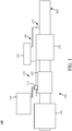
- FIG. 1 depicts an aftertreatment system 100 having an example reductant delivery system 110 for an exhaust system 190.
- the aftertreatment system 100 includes a diesel particulate filter (DPF) 102, the reductant delivery system 110, a decomposition chamber or reactor 104, a SCR catalyst 106, and a sensor probe 150.
- DPF diesel particulate filter
- the DPF 102 is configured to remove particulate matter, such as soot, from exhaust gas flowing in the exhaust system 190.
- the DPF 102 includes an inlet, where the exhaust gas is received, and an outlet, where the exhaust gas exits after having particulate matter substantially filtered from the exhaust gas and/or converting the particulate matter into carbon dioxide.
- the decomposition chamber 104 is configured to convert a reductant, such as urea, aqueous ammonia, or DEF, into ammonia.
- the decomposition chamber 104 includes a reductant delivery system 110 having a dosing module 112 configured to dose the reductant into the decomposition chamber 104.
- the urea, aqueous ammonia, DEF is injected upstream of the SCR catalyst 106.
- the reductant droplets then undergo the processes of evaporation, thermolysis, and hydrolysis to form gaseous ammonia within the exhaust system 190.
- the decomposition chamber 104 includes an inlet in fluid communication with the DPF 102 to receive the exhaust gas containing NO x emissions and an outlet for the exhaust gas, NO x emissions, ammonia, and/or remaining reductant to flow to the SCR catalyst 106.
- the decomposition chamber 104 includes the dosing module 112 mounted to the decomposition chamber 104 such that the dosing module 112 may dose a reductant, such as urea, aqueous ammonia, or DEF, into the exhaust gases flowing in the exhaust system 190.
- the dosing module 112 may include an insulator 114 interposed between a portion of the dosing module 112 and the portion of the decomposition chamber 104 to which the dosing module 112 is mounted.
- the dosing module 112 is fluidly coupled to one or more reductant tanks 116.
- a pump (not shown) may be used to pressurize the reductant tank 116 for delivery to the dosing module 112.
- the reductant tank 116 also includes a tank level sensor.
- the tank level sensor and the dosing module 112 are electrically or communicatively coupled to a controller 120.
- the controller 120 is configured to receive tank level values from the tank level sensor.
- the controller 120 is also configured to control the dosing module 112 to dose reductant into the decomposition chamber 104.
- the controller 120 may include a microprocessor, an application-specific integrated circuit (ASIC), a field-programmable gate array (FPGA), etc., or combinations thereof.
- the controller 120 may include memory which may include, but is not limited to, electronic, optical, magnetic, or any other storage or transmission device capable of providing a processor, ASIC, FPGA, etc. with program instructions.
- the memory may include a memory chip, Electrically Erasable Programmable Read-Only Memory (EEPROM), erasable programmable read only memory (EPROM), flash memory, or any other suitable memory from which the controller 120 can read instructions.
- the instructions may include code from any suitable programming language.
- the controller 120 may be configured to control other components of the exhaust system 190 and/or an engine or other components associated with the exhaust system 190. For instance, the controller 120 may be configured to modify an operating condition of the engine, to modify an operating condition of an EGR valve or system, to initiate or stop a regeneration process, etc.
- the SCR catalyst 106 is configured to assist in the reduction of NOx emissions by accelerating a NOx reduction process between the ammonia and the NOx of the exhaust gas into diatomic nitrogen, water, and/or carbon dioxide.
- the SCR catalyst 106 includes inlet in fluid communication with the decomposition chamber 104 from which exhaust gas and reductant is received and an outlet in fluid communication with an end 192 of the exhaust system 190.
- the exhaust system 190 may further include a diesel oxidation catalyst (DOC) in fluid communication with the exhaust system 190 (e.g., downstream of the SCR catalyst 106 or upstream of the DPF 102) to oxidize hydrocarbons and carbon monoxide in the exhaust gas.
- DOC diesel oxidation catalyst
- the sensor probe 150 may be coupled to the exhaust system 190 to detect a condition of the exhaust gas flowing through the exhaust system 190. While the sensor probe 150 is depicted as positioned downstream of the SCR catalyst 106, it should be understood that the sensor probe 150 may be positioned at any other position of the exhaust system 190, including upstream of the DPF 102, within the DPF 102, between the DPF 102 and the decomposition chamber 104, within the decomposition chamber 104, between the decomposition chamber 104 and the SCR catalyst 106, within the SCR catalyst 106, or downstream of the SCR catalyst 106. Still further configurations for the sensor probes 150 may be implemented.
- the sensor probe 150 is configured to detect a concentration of a compound in the exhaust gas flowing through the exhaust system 190 and to output an output signal to the controller 120.
- the controller 120 may be configured to use the output signal of from the sensor to modify and/or output a control signal to a component of the exhaust system 190, an engine, and/or another component. For instance, the controller 120 may receive the output signal from the sensor 150 and modify the control signal for the dosing module 112 to increase, decrease, and/or maintain an amount of reductant dosed into the exhaust system 190.
- Sensor-estimated tank volumes and commanded urea volumes may be used to diagnose reductant tank level sensors.
- positive or negative gain, or positive or negative offset may be determined.
- a positive or negative gain may occur when the controller determines that the difference between sensor-estimated tank volumes and the command-estimated dosing volume is outside of an acceptable range. In non-defective circumstances, percent drop in tank level equals percent commanded reductant.
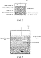
- FIG. 2 is a schematic diagram of a reductant tank according to one embodiment.
- the reductant tank 200 includes four volumetric regions.
- a dead band volume portion, or expansion space 205 accommodates expansion of the reductant fluid.
- a usable volume is located below the expansion space and represents the area where usable reductant is typically located.
- a maximum tank level 210 forms the boundary between the expansion space 205 and the usable volume.
- Below the usable volume is a 10% minimum reserve volume, the top of which corresponds to a reserve volume level 220 and also corresponding to 0% on the vehicle dash gauge.
- a non-consumable heat rejection volume is also provided.
- the non-consumable heat rejection volume is required for coolant recirculation between the dosing module, the reductant tank, and other coolant-required components of the reductant delivery system (i.e. supply unit or pump).
- the reductant tank 200 also includes a suction line 215 and a suction filter 225, both in fluid connection with one or both of a supply unit or the dosing module. The reductant is drawn from the tank reservoir by the suction filter 225, and passed through the suction line 215 for delivery to the aftertreatment system.
- FIG. 3 is schematic diagram of the gain, positive offset, and negative offset diagnostic regions.
- the rationality diagnostic previously summarized and to be described in greater detail below, is performed to diagnose a tank level sensor.
- a large volumetric region, 315 correspond to gain diagnosis.
- Second and third smaller volumetric regions, 310 and 305 correspond to negative offset and positive offset diagnosis, respectively.
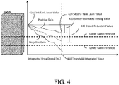
- FIG. 4 is a schematic diagram depicting sensor gain detection according to one embodiment.
- Tank volumes (y axis) and dosing volumes (x axis) are used to diagnose sensor gain.
- a positive or negative gain defect occurs when the controller determines that the difference between sensor-estimated dosing value 430 and the dosed reductant value 440 is outside of a calibration range (the calibration range bound by upper and lower gain thresholds).
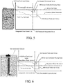
- FIG. 5 is schematic diagram depicting sensor positive offset detection according to one embodiment. A positive offset is detected when the sensor-estimated dosing value 530 is above a positive offset threshold (level drop is unrealistically small).
- FIG. 6 is a schematic diagram depicting sensor negative offset detection according to one embodiment. A negative offset is detected when the sensor-estimated dosing value is above a negative offset threshold. The acceptable offset threshold is represented in the figures by the positive offset and negative offset threshold levels.
- the x-axis represents commanded urea values and the y-axis represents sensor-received tank level values.
- a first tank level value 410 is received from a sensor.
- the volume of urea in the tank decreases.
- a threshold integrated value 450 denoted by the hatched vertical line in the figure
- a second tank level value 420 is received from the sensor.
- the difference between the first tank level value 410 and the second tank level value 420 is the sensor-estimated dosing value 430, or level drop.
- the dosed reductant value 440 represents the plurality of reductant dosing command values integrated over time until the threshold integrated value 450 is reached.
- the sensor-estimated dosing volume 430 is outside of a calibration range, the sensor has a gain.
- the calibration range is bound by upper and lower gain thresholds which place limits on the acceptable difference between the sensor-estimated dosing volume 430 and the dosed reductant value 440.
- the gain is positive; when it is below the lower gain threshold, the gain is negative.
- the x-axis represents commanded urea values.
- the y-axis represents sensor-received tank level values. Initially, a first tank level value 510 (indicative of a full tank) is received from a sensor in response to a refill event. As urea is dispensed into the system based on a plurality of reductant dosing command values, the volume of urea in the tank decreases. When the plurality of reductant dosing command values reach a threshold integrated value 550 (denoted by the hatched vertical line in the figure), a second tank level value 520 is received from the sensor.
- a threshold integrated value 550 denoted by the hatched vertical line in the figure
- the difference between the first tank level value 510 and the second tank level value 520 is the sensor-estimated dosing value 530, or level drop.
- the dosed reductant value 540 represents the plurality of reductant dosing command values integrated over time.
- the sensor-estimated dosing volume 530 is above a positive offset threshold (outside of an acceptable calibration range)
- the sensor has a positive offset. This occurs when the sensor-estimated dosing value is unrealistically small compared to the dosed reductant value 540. If the sensor-estimated dosing value 530 is below the positive offset threshold, there is no positive offset.
- the x-axis represents commanded urea values and the y-axis represents sensor-received tank level values.
- the raw tank level value is monitored to detect the presence of a dead band volume 660.
- a first tank level value 610 is received. If the first tank level value 610 is indicative of a raw tank level above 80% (detection capability is 20% negative offset), then there is not a negative offset defect in the sensor. If the first tank level value 610 is indicative of a tank level value below 80%, commanded urea is monitored and a plurality of reductant dosing command values are received from the sensor.
- a second tank level value 620 is received from the sensor.
- the difference between the first tank level value 610 and the second tank level value 620 is the sensor-estimated dosing value 630, or level drop.
- the dosed reductant value 640 represents the plurality of reductant dosing command values integrated over time.
- the sensor-estimated dosing value 630 is above a negative offset threshold (outside of an acceptable calibration range)
- the sensor has a negative offset. This occurs when the sensor-estimated dosing volume is unrealistically small compared to the dosed reductant value 640. If the sensor-estimated dosing value 630 is below the negative offset threshold, there is no negative offset.
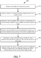
- FIG. 7 depicts an example process 700 that may be implemented by the system 190 for diagnosing sensor gain.
- the process 700 may be used to detect both positive and negative sensor gain.
- the process 700 includes, at 710, receiving a first tank level value from a sensor.
- a plurality of reductant dosing command values are received over a period of time.
- a dosed reductant value is determined responsive to the plurality of reductant dosing command values reaching a threshold integrated value.
- a second tank level value is received from the sensor responsive to the dosed reductant value reaching the threshold integrated value.
- a sensor-estimated dosing value is determined based on the difference between the first tank level value and the second tank level value.
- it is diagnosed whether the sensor is performing within an acceptable calibration range based on the difference between the sensor-estimated dosing value and the dosed reductant value.
- FIG. 8 is a schematic flow chart depicting a process 800 that may be implemented by the system for diagnosing sensor gain.
- urea dosing commands are received.
- the urea dosing commands are integrated (converted to a value indicative of a volume).
- raw tank level values are received from a sensor.
- the raw tank levels are conditioned for use in performing rationality diagnostics on the sensor.
- the integrated urea dosing commands and conditioned raw tank level values are recorded. The slope of the recorded conditioned raw tank levels and integrated commanded urea is calculated at 860.
- rationality diagnostics are performed on the sensor and a sensor gain diagnostic decision is made.
- the process 800 repeats itself in response to the diagnostic decision, a refill detection (reset), or other reset event.
- FIG. 9 is a chart depicting an exemplary rationality diagnostic for sensor gain according to one embodiment.
- the chart depicts raw tank level values received over time as well as conditioned tank level values used in the rationality diagnostics of the sensor, as well as corresponding positive and negative offset detection and related diagnostic decisions. In the example, four diagnostic decisions are made in response to each refill/reset event.
- FIG. 10 is a chart depicting an exemplary rationality diagnostic for sensor positive offset according to one embodiment.
- the chart depicts raw tank level values received over time as well as conditioned tank level values used in the rationality diagnostics of the sensor, as well as corresponding positive and negative offset detection and related diagnostic decisions. In the example, the sensor is monitored for positive offset but the offset is determined to be less than the positive offset threshold.
- FIG. 10 is a chart depicting an exemplary rationality diagnostic for sensor gain according to one embodiment. The chart depicts raw tank level values received over time as well as conditioned tank level values used in the rationality diagnostics of the sensor, as well as corresponding positive and negative offset detection and related
- FIG. 11 is a chart depicting an exemplary rationality diagnostic for sensor negative offset according to one embodiment.
- the chart depicts raw tank level values received over time, conditioned tank level values used in the rationality diagnostics of the sensor, and corresponding positive and negative offset detection and related diagnostic decisions.
- the sensor is monitored for negative offset but the offset is greater than the negative offset threshold.
- the systems or processes described herein can include a controller structured to perform certain operations described herein.
- the controller forms a portion of a processing subsystem including one or more computing devices having memory, processing, and communication hardware.
- the controller may be a single device or a distributed device, and the functions of the controller may be performed by hardware and/or as computer instructions on a non-transient computer readable storage medium.
- the controller includes one or more modules structured to functionally execute the operations of the controller.
- modules structured to functionally execute the operations of the controller.
- the description herein including modules emphasizes the structural independence of the aspects of the controller, and illustrates one grouping of operations and responsibilities of the controller. Other groupings that execute similar overall operations are understood within the scope of the present application. Modules may be implemented in hardware and/or as computer instructions on a non-transient computer readable storage medium, and modules may be distributed across various hardware or computer based components. More specific descriptions of certain embodiments of controller operations are included in the section referencing Figures 2-6 .
- Example and non-limiting module implementation elements include sensors providing any value determined herein, sensors providing any value that is a precursor to a value determined herein, datalink and/or network hardware including communication chips, oscillating crystals, communication links, cables, twisted pair wiring, coaxial wiring, shielded wiring, transmitters, receivers, and/or transceivers, logic circuits, hard-wired logic circuits, reconfigurable logic circuits in a particular non-transient state configured according to the module specification, any actuator including at least an electrical, hydraulic, or pneumatic actuator, a solenoid, an op-amp, analog control elements (springs, filters, integrators, adders, dividers, gain elements), and/or digital control elements.
- datalink and/or network hardware including communication chips, oscillating crystals, communication links, cables, twisted pair wiring, coaxial wiring, shielded wiring, transmitters, receivers, and/or transceivers, logic circuits, hard-wired logic circuits, reconfigurable logic circuits in a particular non-transient
- controller encompasses all kinds of apparatus, devices, and machines for processing data, including by way of example a programmable processor, a computer, a system on a chip, or multiple ones, a portion of a programmed processor, or combinations of the foregoing.
- the apparatus can include special purpose logic circuitry, e.g., an FPGA or an ASIC.
- the apparatus can also include, in addition to hardware, code that creates an execution environment for the computer program in question, e.g., code that constitutes processor firmware, a protocol stack, a database management system, an operating system, a cross-platform runtime environment, a virtual machine, or a combination of one or more of them.
- the apparatus and execution environment can realize various different computing model infrastructures, such as distributed computing and grid computing infrastructures.
Landscapes
- Engineering & Computer Science (AREA)
- Chemical & Material Sciences (AREA)
- Combustion & Propulsion (AREA)
- Mechanical Engineering (AREA)
- General Engineering & Computer Science (AREA)
- Chemical Kinetics & Catalysis (AREA)
- Health & Medical Sciences (AREA)
- Toxicology (AREA)
- Exhaust Gas After Treatment (AREA)
Description
- The present application relates generally to the field of sensors for an aftertreatment system.
- For internal combustion engines, such as diesel engines, nitrogen oxides (NOx) compounds may be emitted in the exhaust. To reduce NOx emissions, a selective catalytic reduction (SCR) process may be implemented to convert the NOx compounds into more neutral compounds, such as diatomic nitrogen, water, or carbon dioxide, with the aid of a catalyst and a reductant. The catalyst may be included in a catalyst chamber of an exhaust system, such as that of a vehicle. A reductant, such as anhydrous ammonia, aqueous ammonia, or urea, is typically introduced into the exhaust gas flow prior to the catalyst chamber. To introduce the reductant into the exhaust gas flow for the SCR process, an SCR system may dose or otherwise introduce the reductant through a dosing module that vaporizes or sprays the reductant into an exhaust pipe of the exhaust system upstream of the catalyst chamber.
- Prior to being dosed into the exhaust pipe of the exhaust system, the reductant is stored in a tank and engines may monitor the amount of reductant, such as urea or diesel exhaust fluid (DEF) present in the tank. To monitor the amount of stored reductant, a sensor or multiple sensors may be coupled to the tank. In some systems, the stored reductant is also used as coolant for the dosing module. Use of urea or DEF as a coolant requires a reserve amount of the reductant be present in the tank to allow for recirculation. At low tank-level sensor values, dosing must stop to ensure sufficient urea for coolant recirculation, which brings tank-level sensors within the scope of the on-board diagnostic system. Thus, various OBD requirements, including requirements stipulated by the United States Environmental Protection Agency (EPA) and the California Air Resources Board (CARB), mandate diagnosing these tank-level sensors as part of NOx emission reduction control.
-
EP2071145 discloses an exhaust emission purifying apparatus for reductively purifying NOx in exhaust emission by using a liquid reducing agent or its precursor (referred to as "liquid reducing agent"). A dosing flow rate of the liquid reducing agent according to engine operating conditions is computed, and the dosing of the liquid reducing agent is controlled based on the computed dosing flow rate. It is judged whether or not a supply system of the liquid reducing agent is failed, based on a ratio between an integrated amount obtained by sequentially integrating the dosing flow rate and a consumed amount of the liquid reducing agent. -
WO2013157095 discloses an engine equipped with a tank that stores urea water, a level sensor that detects the amount of urea water remaining in the tank, and a urea injection valve that injects urea water in the tank into an exhaust passage. A control device determines whether misdetection is made in the level sensor on the basis of a first urea remaining amount detected by the level sensor immediately after the engine has stopped, and an integrated value for the urea water supply amount, and a second urea remaining amount detected by the level sensor after the supplying of urea water has begun. When the control device determines that misdetection is made in the level sensor, the control device sets, as the estimated value for the amount of urea in the tank, the value obtained by subtracting the integrated value for the urea water supply amount from the first urea remaining amount. - According to a first aspect of the invention there is provided a computer-implemented method for diagnosing a sensor of a reductant tank of an exhaust aftertreatment system, comprising receiving a first tank level value from the sensor, receiving a plurality of reductant dosing command values over a period of time, determining a dosed reductant value responsive to the plurality of reductant dosing command values reaching a threshold integrated value, receiving a second tank level value from the sensor responsive to the dosed reductant value reaching the threshold integrated value, determining a sensor-estimated dosing value based on the difference between the first tank level value and the second tank level value, and diagnosing whether the sensor is performing outside of an acceptable calibration range based on the difference between the sensor-estimated dosing value and the dosed reductant value based on the sensor-estimated dosing value corresponding to a tank volume that is above the upper gain threshold value or below the lower gain threshold value.
- The plurality of reductant dosing command values and the first tank level value may be received after a reset event responsive to a previous diagnostic decision or a refill detection.
- The method may further comprise determining an upper gain threshold value and a lower gain threshold value based on the dosed reductant value.
The method may further comprise sending a diagnostic decision to a monitoring device indicating that the sensor has a positive gain in response to tank volume that is above the upper gain threshold value. - The method may further comprise sending a diagnostic decision to a monitoring device indicating the sensor has a negative gain in response to a tank volume that is below the lower gain threshold value.
The method may further comprise determining if the first tank level value is indicative of a reductant tank that is initially full, and determining a positive offset threshold value based on the dosed reductant value, wherein the diagnosing the sensor based on the difference between the sensor estimated dosing value and the dosed reductant value determines the sensor is performing outside of the acceptable calibration range based on the sensor-estimated dosing value corresponding to a tank volume that is above the positive offset threshold value.
The method may further comprise sending a diagnostic decision to a monitoring device indicating the sensor has a positive offset. - The method may further comprise determining if the first tank level value is indicative of a reductant tank that is initially less than 80% full, and determining a negative offset threshold value based on the dosed reductant value, wherein the diagnosing the sensor based on the difference between the sensor estimated dosing value and the dosed reductant value determines the sensor is performing outside of the acceptable calibration range based on the sensor-estimated dosing value corresponding to a tank volume that is above the negative offset threshold value.
- The method may further comprise sending a diagnostic decision to a monitoring device indicating the sensor has a negative offset.
- The method may further comprise detecting the presence of a dead band volume within the reductant tank prior to performing negative offset rationality diagnostics on the sensor.
- The first tank level value and the second tank level value may be conditioned values derived from raw tank level values.
- The threshold integrated value may be indicative of 20% of usable reductant in the tank being dosed into the system.
- The method may further comprise sending a diagnostic decision to a monitoring device indicating whether the sensor is performing within the acceptable calibration range or is defective.
- According to a second aspect of the invention there is provided a system for diagnosing a sensor of an exhaust aftertreatment system, comprising a controller configured to perform the computerized method of the first aspect of the invention.
- The controller may further be configured to perform one or more of the optional methods of the first aspect of the invention set out above.
- According to a third aspect of the invention there is provided an apparatus for diagnosing a sensor of a reductant tank of an exhaust aftertreatment system comprising one or more modules configured to perform the operations of the first aspect of the invention.
- The apparatus may further be configured to perform one or more of the optional operations of the first aspect of the invention set out above.
- The details of one or more implementations are set forth in the accompanying drawings and the description below. Other features, aspects, and advantages of the disclosure will become apparent from the description, the drawings, and the claims, in which:
-
FIG. 1 is a schematic block diagram of a selective catalytic reduction system having a reductant delivery system for an exhaust system; -
FIG. 2 is a schematic diagram of a reductant tank according to one embodiment. -
FIG. 3 is a schematic diagram of gain, positive offset, and negative offset diagnostic regions. -
FIG. 4 is a schematic diagram depicting sensor gain diagnosis according to one embodiment -
FIG. 5 is schematic diagram depicting sensor positive offset diagnosis according to one embodiment. -
FIG. 6 is a schematic diagram depicting sensor negative offset diagnosis according to one embodiment. -
FIG. 7 is a process diagram for a process of diagnosing sensor gain. -
FIG. 8 is a schematic flow chart depicting a process of diagnosing sensor gain according to one embodiment -
FIG. 9 is a chart depicting an exemplary rationality diagnostic for sensor gain according to one embodiment. -
FIG. 10 is a chart depicting an exemplary rationality diagnostic for sensor positive offset according to one embodiment. -
FIG. 11 is a chart depicting an exemplary rationality diagnostic for sensor negative according to one embodiment. - It will be recognized that some or all of the figures are schematic representations for purposes of illustration. The figures are provided for the purpose of illustrating one or more implementations with the explicit understanding that they will not be used to limit the scope or the meaning of the claims.
- Following below are more detailed descriptions of various concepts related to, and implementations of, methods, apparatuses, and systems for diagnosing rationality of a sensor for a reductant tank. The various concepts introduced above and discussed in greater detail below may be implemented in any of numerous ways, as the described concepts are not limited to any particular manner of implementation. Examples of specific implementations and applications are provided primarily for illustrative purposes.
- One or more sensors are utilized to determine and/or estimate the amount of reductant within a storage tank. However, such sensors may be faulty initially and/or degrade over time and/or usage. For instance, a sensor may develop an abnormal gain for an output value from the sensor and/or an abnormal offset to the output value from the sensor. Such characteristics, gain and/or offset, of the output signal of the sensor may negatively affect an aftertreatment system of the engine by making the system assume there is more or less reductant in the tank than is actually present. In the case of a reductant-cooled dosing module, a high assumption defect could cause damage to the dosing module by allowing the system to dose reductant beyond the minimum level required to maintain coolant recirculation. A low assumption defect could cause the dosing module to stop dosing prematurely, negatively affecting the performance of the aftertreatment system. Thus, determining whether the sensor is defective or not defective can impact various aspects of an aftertreatment system and/or engine.
- Implementations described herein involve performing rationality diagnoses to determine whether the sensor is defective or not defective. In general, a rationality diagnosis of a sensor involves comparing a sensor reported value to a reference value and identifying any low or high biases in the reported value. In some implementations, an algorithmic rationality diagnosis is performed by a controller comparing a sensor-estimated dosing value with a dosed reductant value determined from integrated commanded reductant feedback. The sensor-estimated dosing value is based on the difference between two sensor-estimated tank levels at the beginning and end of a monitored time period. The dosed reductant value is based on commanded reductant feedback integrated over the same monitored time period.
- In one scenario, the controller may determine that the sensor has a positive or negative gain defect in response to a comparison of the sensor-estimated dosing value and the dosed reductant value. A positive or negative gain defect may occur when the tank level corresponding with the sensor-estimated dosing value is greater or less than threshold reference values.
- In another scenario, the controller may determine that the sensor has a positive offset. This may occur when, after determining that the tank is initially full, the controller determines the drop in the tank level corresponding to the sensor-estimated dosing value is less than a predetermined dosed reductant value. In yet another scenario, the controller may determine that the sensor has a negative offset. This may occur when, after determining that the tank level is initially less than a calibration value-for example, a tank level indicating the tank is 80 percent full-the controller determines the drop in the tank level corresponding to the sensor-estimated dosing value is less than a predetermined dosed reductant value. In the offset scenario, a sensor would falsely indicate a tank level that appears constant due to the existence of a dead-band volume (the excess volume at the top of the tank beyond which the tank level sensor would report 100 percent).
- In any of the aforementioned implementations, the controller determines the sensor is defective or not defective irrespective of the underlying technology of the sensing mechanism.
-
FIG. 1 depicts anaftertreatment system 100 having an examplereductant delivery system 110 for anexhaust system 190. Theaftertreatment system 100 includes a diesel particulate filter (DPF) 102, thereductant delivery system 110, a decomposition chamber orreactor 104, aSCR catalyst 106, and asensor probe 150. - The
DPF 102 is configured to remove particulate matter, such as soot, from exhaust gas flowing in theexhaust system 190. TheDPF 102 includes an inlet, where the exhaust gas is received, and an outlet, where the exhaust gas exits after having particulate matter substantially filtered from the exhaust gas and/or converting the particulate matter into carbon dioxide. - The
decomposition chamber 104 is configured to convert a reductant, such as urea, aqueous ammonia, or DEF, into ammonia. Thedecomposition chamber 104 includes areductant delivery system 110 having adosing module 112 configured to dose the reductant into thedecomposition chamber 104. In some implementations, the urea, aqueous ammonia, DEF is injected upstream of theSCR catalyst 106. The reductant droplets then undergo the processes of evaporation, thermolysis, and hydrolysis to form gaseous ammonia within theexhaust system 190. Thedecomposition chamber 104 includes an inlet in fluid communication with theDPF 102 to receive the exhaust gas containing NOx emissions and an outlet for the exhaust gas, NOx emissions, ammonia, and/or remaining reductant to flow to theSCR catalyst 106. - The
decomposition chamber 104 includes thedosing module 112 mounted to thedecomposition chamber 104 such that thedosing module 112 may dose a reductant, such as urea, aqueous ammonia, or DEF, into the exhaust gases flowing in theexhaust system 190. Thedosing module 112 may include aninsulator 114 interposed between a portion of thedosing module 112 and the portion of thedecomposition chamber 104 to which thedosing module 112 is mounted. Thedosing module 112 is fluidly coupled to one ormore reductant tanks 116. In some implementations, a pump (not shown) may be used to pressurize thereductant tank 116 for delivery to thedosing module 112. Thereductant tank 116 also includes a tank level sensor. - The tank level sensor and the
dosing module 112 are electrically or communicatively coupled to acontroller 120. Thecontroller 120 is configured to receive tank level values from the tank level sensor. Thecontroller 120 is also configured to control thedosing module 112 to dose reductant into thedecomposition chamber 104. Thecontroller 120 may include a microprocessor, an application-specific integrated circuit (ASIC), a field-programmable gate array (FPGA), etc., or combinations thereof. Thecontroller 120 may include memory which may include, but is not limited to, electronic, optical, magnetic, or any other storage or transmission device capable of providing a processor, ASIC, FPGA, etc. with program instructions. The memory may include a memory chip, Electrically Erasable Programmable Read-Only Memory (EEPROM), erasable programmable read only memory (EPROM), flash memory, or any other suitable memory from which thecontroller 120 can read instructions. The instructions may include code from any suitable programming language. Thecontroller 120 may be configured to control other components of theexhaust system 190 and/or an engine or other components associated with theexhaust system 190. For instance, thecontroller 120 may be configured to modify an operating condition of the engine, to modify an operating condition of an EGR valve or system, to initiate or stop a regeneration process, etc. - The
SCR catalyst 106 is configured to assist in the reduction of NOx emissions by accelerating a NOx reduction process between the ammonia and the NOx of the exhaust gas into diatomic nitrogen, water, and/or carbon dioxide. TheSCR catalyst 106 includes inlet in fluid communication with thedecomposition chamber 104 from which exhaust gas and reductant is received and an outlet in fluid communication with anend 192 of theexhaust system 190. - The
exhaust system 190 may further include a diesel oxidation catalyst (DOC) in fluid communication with the exhaust system 190 (e.g., downstream of theSCR catalyst 106 or upstream of the DPF 102) to oxidize hydrocarbons and carbon monoxide in the exhaust gas. - The
sensor probe 150 may be coupled to theexhaust system 190 to detect a condition of the exhaust gas flowing through theexhaust system 190. While thesensor probe 150 is depicted as positioned downstream of theSCR catalyst 106, it should be understood that thesensor probe 150 may be positioned at any other position of theexhaust system 190, including upstream of theDPF 102, within theDPF 102, between theDPF 102 and thedecomposition chamber 104, within thedecomposition chamber 104, between thedecomposition chamber 104 and theSCR catalyst 106, within theSCR catalyst 106, or downstream of theSCR catalyst 106. Still further configurations for the sensor probes 150 may be implemented. - In some implementations, the
sensor probe 150 is configured to detect a concentration of a compound in the exhaust gas flowing through theexhaust system 190 and to output an output signal to thecontroller 120. Thecontroller 120 may be configured to use the output signal of from the sensor to modify and/or output a control signal to a component of theexhaust system 190, an engine, and/or another component. For instance, thecontroller 120 may receive the output signal from thesensor 150 and modify the control signal for thedosing module 112 to increase, decrease, and/or maintain an amount of reductant dosed into theexhaust system 190. - Sensor-estimated tank volumes and commanded urea volumes may be used to diagnose reductant tank level sensors. In particular, positive or negative gain, or positive or negative offset may be determined. A positive or negative gain may occur when the controller determines that the difference between sensor-estimated tank volumes and the command-estimated dosing volume is outside of an acceptable range. In non-defective circumstances, percent drop in tank level equals percent commanded reductant.
-
FIG. 2 is a schematic diagram of a reductant tank according to one embodiment. Thereductant tank 200 includes four volumetric regions. A dead band volume portion, orexpansion space 205, accommodates expansion of the reductant fluid. A usable volume is located below the expansion space and represents the area where usable reductant is typically located. Amaximum tank level 210 forms the boundary between theexpansion space 205 and the usable volume. Below the usable volume is a 10% minimum reserve volume, the top of which corresponds to areserve volume level 220 and also corresponding to 0% on the vehicle dash gauge. A non-consumable heat rejection volume is also provided. The non-consumable heat rejection volume is required for coolant recirculation between the dosing module, the reductant tank, and other coolant-required components of the reductant delivery system (i.e. supply unit or pump). Thereductant tank 200 also includes asuction line 215 and asuction filter 225, both in fluid connection with one or both of a supply unit or the dosing module. The reductant is drawn from the tank reservoir by thesuction filter 225, and passed through thesuction line 215 for delivery to the aftertreatment system. -
FIG. 3 is schematic diagram of the gain, positive offset, and negative offset diagnostic regions. The rationality diagnostic, previously summarized and to be described in greater detail below, is performed to diagnose a tank level sensor. The diagnostic performed for each fault category-gain, positive offset, negative offset-corresponds with a particular volumetric region of thereductant tank 300. A large volumetric region, 315 correspond to gain diagnosis. Second and third smaller volumetric regions, 310 and 305, correspond to negative offset and positive offset diagnosis, respectively. -
FIG. 4 is a schematic diagram depicting sensor gain detection according to one embodiment. Tank volumes (y axis) and dosing volumes (x axis) are used to diagnose sensor gain. A positive or negative gain defect occurs when the controller determines that the difference between sensor-estimateddosing value 430 and the dosedreductant value 440 is outside of a calibration range (the calibration range bound by upper and lower gain thresholds).FIG. 5 is schematic diagram depicting sensor positive offset detection according to one embodiment. A positive offset is detected when the sensor-estimateddosing value 530 is above a positive offset threshold (level drop is unrealistically small). Similarly,FIG. 6 is a schematic diagram depicting sensor negative offset detection according to one embodiment. A negative offset is detected when the sensor-estimated dosing value is above a negative offset threshold. The acceptable offset threshold is represented in the figures by the positive offset and negative offset threshold levels. - Referring again to the gain detection diagram of
FIG. 4 , the x-axis represents commanded urea values and the y-axis represents sensor-received tank level values. Initially, a firsttank level value 410 is received from a sensor. As urea is dispensed into the system based on a plurality of reductant dosing command values, the volume of urea in the tank decreases. When the plurality of reductant dosing command values reach a threshold integrated value 450 (denoted by the hatched vertical line in the figure), a secondtank level value 420 is received from the sensor. The difference between the firsttank level value 410 and the secondtank level value 420 is the sensor-estimateddosing value 430, or level drop. The dosedreductant value 440 represents the plurality of reductant dosing command values integrated over time until the threshold integratedvalue 450 is reached. When the sensor-estimateddosing volume 430 is outside of a calibration range, the sensor has a gain. The calibration range is bound by upper and lower gain thresholds which place limits on the acceptable difference between the sensor-estimateddosing volume 430 and the dosedreductant value 440. When the sensor-estimateddosing volume 430 is above the upper gain threshold, the gain is positive; when it is below the lower gain threshold, the gain is negative. - Referring again to the positive offset detection diagram of
FIG. 5 , in accordance with one embodiment, the x-axis represents commanded urea values. The y-axis represents sensor-received tank level values. Initially, a first tank level value 510 (indicative of a full tank) is received from a sensor in response to a refill event. As urea is dispensed into the system based on a plurality of reductant dosing command values, the volume of urea in the tank decreases. When the plurality of reductant dosing command values reach a threshold integrated value 550 (denoted by the hatched vertical line in the figure), a secondtank level value 520 is received from the sensor. The difference between the firsttank level value 510 and the secondtank level value 520 is the sensor-estimateddosing value 530, or level drop. The dosedreductant value 540 represents the plurality of reductant dosing command values integrated over time. When the sensor-estimateddosing volume 530 is above a positive offset threshold (outside of an acceptable calibration range), the sensor has a positive offset. This occurs when the sensor-estimated dosing value is unrealistically small compared to the dosedreductant value 540. If the sensor-estimateddosing value 530 is below the positive offset threshold, there is no positive offset. - Referring again to the negative offset detection diagram of
FIG. 6 , in accordance with one embodiment, the x-axis represents commanded urea values and the y-axis represents sensor-received tank level values. To detect a negative offset, the raw tank level value is monitored to detect the presence of adead band volume 660. Thus, initially, a firsttank level value 610 is received. If the firsttank level value 610 is indicative of a raw tank level above 80% (detection capability is 20% negative offset), then there is not a negative offset defect in the sensor. If the firsttank level value 610 is indicative of a tank level value below 80%, commanded urea is monitored and a plurality of reductant dosing command values are received from the sensor. When the plurality of reductant dosing command values reach a threshold integrated value 650 (denoted by the hatched vertical line in the figure), a secondtank level value 620 is received from the sensor. The difference between the firsttank level value 610 and the secondtank level value 620 is the sensor-estimateddosing value 630, or level drop. The dosedreductant value 640 represents the plurality of reductant dosing command values integrated over time. When the sensor-estimateddosing value 630 is above a negative offset threshold (outside of an acceptable calibration range), the sensor has a negative offset. This occurs when the sensor-estimated dosing volume is unrealistically small compared to the dosedreductant value 640. If the sensor-estimateddosing value 630 is below the negative offset threshold, there is no negative offset. -
FIG. 7 depicts anexample process 700 that may be implemented by thesystem 190 for diagnosing sensor gain. Theprocess 700 may be used to detect both positive and negative sensor gain. Theprocess 700 includes, at 710, receiving a first tank level value from a sensor. At 720, a plurality of reductant dosing command values are received over a period of time. At 730, a dosed reductant value is determined responsive to the plurality of reductant dosing command values reaching a threshold integrated value. At 740, a second tank level value is received from the sensor responsive to the dosed reductant value reaching the threshold integrated value. At 750, a sensor-estimated dosing value is determined based on the difference between the first tank level value and the second tank level value. At 760, it is diagnosed whether the sensor is performing within an acceptable calibration range based on the difference between the sensor-estimated dosing value and the dosed reductant value. -
FIG. 8 is a schematic flow chart depicting aprocess 800 that may be implemented by the system for diagnosing sensor gain. At 810, urea dosing commands are received. At 830, the urea dosing commands are integrated (converted to a value indicative of a volume). At 820, raw tank level values are received from a sensor. At 840, the raw tank levels are conditioned for use in performing rationality diagnostics on the sensor. At 850, the integrated urea dosing commands and conditioned raw tank level values are recorded. The slope of the recorded conditioned raw tank levels and integrated commanded urea is calculated at 860. At 870, rationality diagnostics are performed on the sensor and a sensor gain diagnostic decision is made. Theprocess 800 repeats itself in response to the diagnostic decision, a refill detection (reset), or other reset event. -
FIG. 9 is a chart depicting an exemplary rationality diagnostic for sensor gain according to one embodiment. The chart depicts raw tank level values received over time as well as conditioned tank level values used in the rationality diagnostics of the sensor, as well as corresponding positive and negative offset detection and related diagnostic decisions. In the example, four diagnostic decisions are made in response to each refill/reset event. Similarly,FIG. 10 is a chart depicting an exemplary rationality diagnostic for sensor positive offset according to one embodiment. The chart depicts raw tank level values received over time as well as conditioned tank level values used in the rationality diagnostics of the sensor, as well as corresponding positive and negative offset detection and related diagnostic decisions. In the example, the sensor is monitored for positive offset but the offset is determined to be less than the positive offset threshold.FIG. 11 is a chart depicting an exemplary rationality diagnostic for sensor negative offset according to one embodiment. The chart depicts raw tank level values received over time, conditioned tank level values used in the rationality diagnostics of the sensor, and corresponding positive and negative offset detection and related diagnostic decisions. In the example, the sensor is monitored for negative offset but the offset is greater than the negative offset threshold. - In certain implementations, the systems or processes described herein can include a controller structured to perform certain operations described herein. In certain implementations, the controller forms a portion of a processing subsystem including one or more computing devices having memory, processing, and communication hardware. The controller may be a single device or a distributed device, and the functions of the controller may be performed by hardware and/or as computer instructions on a non-transient computer readable storage medium.
- In certain implementations, the controller includes one or more modules structured to functionally execute the operations of the controller. The description herein including modules emphasizes the structural independence of the aspects of the controller, and illustrates one grouping of operations and responsibilities of the controller. Other groupings that execute similar overall operations are understood within the scope of the present application. Modules may be implemented in hardware and/or as computer instructions on a non-transient computer readable storage medium, and modules may be distributed across various hardware or computer based components. More specific descriptions of certain embodiments of controller operations are included in the section referencing
Figures 2-6 . - Example and non-limiting module implementation elements include sensors providing any value determined herein, sensors providing any value that is a precursor to a value determined herein, datalink and/or network hardware including communication chips, oscillating crystals, communication links, cables, twisted pair wiring, coaxial wiring, shielded wiring, transmitters, receivers, and/or transceivers, logic circuits, hard-wired logic circuits, reconfigurable logic circuits in a particular non-transient state configured according to the module specification, any actuator including at least an electrical, hydraulic, or pneumatic actuator, a solenoid, an op-amp, analog control elements (springs, filters, integrators, adders, dividers, gain elements), and/or digital control elements.
- The term "controller" encompasses all kinds of apparatus, devices, and machines for processing data, including by way of example a programmable processor, a computer, a system on a chip, or multiple ones, a portion of a programmed processor, or combinations of the foregoing. The apparatus can include special purpose logic circuitry, e.g., an FPGA or an ASIC. The apparatus can also include, in addition to hardware, code that creates an execution environment for the computer program in question, e.g., code that constitutes processor firmware, a protocol stack, a database management system, an operating system, a cross-platform runtime environment, a virtual machine, or a combination of one or more of them. The apparatus and execution environment can realize various different computing model infrastructures, such as distributed computing and grid computing infrastructures.
- While this specification contains many specific implementation details, these should not be construed as limitations on the scope of what may be claimed, but rather as descriptions of features specific to particular implementations.
- It is important to note that the construction and arrangement of the system shown in the various exemplary implementations is illustrative only and not restrictive in character. All changes and modifications that come within the scope of the claims are desired to be protected. It should be understood that some features may not be necessary and implementations lacking the various features may be contemplated as within the scope of the application, the scope of the invention being defined by the claims that follow. In reading the claims, it is intended that when words such as "a," "an," "at least one," or "at least one portion" are used there is no intention to limit the claim to only one item unless specifically stated to the contrary in the claim.
Claims (14)
- A computer-implemented method for diagnosing a sensor of a reductant tank (116) of an exhaust aftertreatment system (100), comprising:receiving a first tank level value (410, 510, 610, 710) from the sensor;receiving a plurality of reductant dosing command values (720) over a period of time;determining a dosed reductant value (440, 540, 640, 730) responsive to the plurality of reductant dosing command values reaching a threshold integrated value (450, 550, 650);receiving a second tank level value (420, 520, 620, 740) from the sensor responsive to the dosed reductant value reaching the threshold integrated value;determining a sensor-estimated dosing value (430, 530, 630, 750) based on the difference between the first tank level value and the second tank level value;determining an upper gain threshold value and a lower gain threshold value based on the dosed reductant value; anddiagnosing (760) whether the sensor is performing outside of an acceptable calibration range based on the difference between the sensor-estimated dosing value and the dosed reductant value, the sensor being diagnosed as performing outside of the acceptable calibration range when the sensor-estimated dosing value corresponds to a tank volume that is above the upper gain threshold value or below the lower gain threshold value.
- The computer-implemented method of claim 1, wherein the plurality of reductant dosing command values (720) and the first tank level value are received after a reset event responsive to a previous diagnostic decision or a refill detection.
- The computer-implemented method of claim 1, further comprising sending a diagnostic decision to a monitoring device indicating that the sensor has a positive gain in response to the tank volume being above the upper gain threshold value.
- The computer-implemented method of claim 1, further comprising sending a diagnostic decision to a monitoring device indicating the sensor has a negative gain in response to the tank volume being below the lower gain threshold value.
- The computer-implemented method of claim 2, further comprising:determining if the first tank level value (510) is indicative of a reductant tank (116) that is initially full; anddetermining a positive offset threshold value based on the dosed reductant value (540),wherein the diagnosing the sensor based on the difference between the sensor-estimated dosing value (530) and the dosed reductant value (540) determines the sensor is performing outside of the acceptable calibration range based on the sensor-estimated dosing value (530) corresponding to a tank volume that is above the positive offset threshold value.
- The computer-implemented method of claim 5, further comprising sending a diagnostic decision to a monitoring device indicating the sensor has a positive offset.
- The computer-implemented method of claim 2, further comprising:determining if the first tank level value (610) is indicative of a reductant tank (116) that is initially less than 80% full; anddetermining a negative offset threshold value based on the dosed reductant value (640),wherein the diagnosing the sensor based on the difference between the sensor-estimated dosing value (630) and the dosed reductant value (640) determines the sensor is performing outside of the acceptable calibration range based on the sensor-estimated dosing value (630) corresponding to a tank volume that is above the negative offset threshold value.
- The computer-implemented method of claim 7, further comprising sending a diagnostic decision to a monitoring device indicating the sensor has a negative offset.
- The computer-implemented method of claim 7, further comprising detecting the presence of a dead band volume (660) within the reductant tank (116) prior to performing negative offset rationality diagnostics on the sensor.
- The computer-implemented method of claim 1, wherein the first tank level value (410, 510, 610, 710) and the second tank level value (420, 520, 620, 740) are conditioned values derived from raw tank level values.
- The computer-implemented method of claim 1, wherein the threshold integrated value is indicative of 20% of usable reductant in the tank (116) being dosed into the system.
- The computer-implemented method of any preceding claim, further comprising sending a diagnostic decision to a monitoring device indicating whether the sensor is performing within the acceptable calibration range or is defective.
- A system for diagnosing a sensor of an exhaust aftertreatment system, comprising a controller configured to perform the computerized method of any of claims 1-12.
- An apparatus for diagnosing a sensor of a reductant tank (116) of an exhaust aftertreatment system comprising one or more modules configured to perform the operations of any of claims 1-12.
Priority Applications (4)
| Application Number | Priority Date | Filing Date | Title |
|---|---|---|---|
| EP14180096.1A EP2982839B8 (en) | 2014-08-06 | 2014-08-06 | Reductant tank sensor diagnostic method and system |
| US14/530,091 US10094264B2 (en) | 2014-08-06 | 2014-10-31 | Reductant tank sensor diagnostic method and system |
| CN201510472201.6A CN106194363B (en) | 2014-08-06 | 2015-08-05 | Method and system for sensor diagnostics of a reductant tank |
| CN201811426372.5A CN109356694B8 (en) | 2014-08-06 | 2015-08-05 | Method and system for sensor diagnostics of reductant tank |
Applications Claiming Priority (1)
| Application Number | Priority Date | Filing Date | Title |
|---|---|---|---|
| EP14180096.1A EP2982839B8 (en) | 2014-08-06 | 2014-08-06 | Reductant tank sensor diagnostic method and system |
Publications (3)
| Publication Number | Publication Date |
|---|---|
| EP2982839A1 EP2982839A1 (en) | 2016-02-10 |
| EP2982839B1 true EP2982839B1 (en) | 2017-10-18 |
| EP2982839B8 EP2982839B8 (en) | 2019-08-14 |
Family
ID=51292841
Family Applications (1)
| Application Number | Title | Priority Date | Filing Date |
|---|---|---|---|
| EP14180096.1A Active EP2982839B8 (en) | 2014-08-06 | 2014-08-06 | Reductant tank sensor diagnostic method and system |
Country Status (3)
| Country | Link |
|---|---|
| US (1) | US10094264B2 (en) |
| EP (1) | EP2982839B8 (en) |
| CN (2) | CN109356694B8 (en) |
Cited By (1)
| Publication number | Priority date | Publication date | Assignee | Title |
|---|---|---|---|---|
| LU504887B1 (en) * | 2023-08-09 | 2025-02-10 | Plastic Omnium Advanced Innovation And Res Sa | Method for determining an amount of a fluid in a container of a vehicle |
Families Citing this family (27)
| Publication number | Priority date | Publication date | Assignee | Title |
|---|---|---|---|---|
| US10107170B2 (en) | 2016-11-14 | 2018-10-23 | GM Global Technology Operations LLC | Method for validating signals generated by acoustic sensors |
| CN108691610A (en) * | 2017-04-07 | 2018-10-23 | 福特环球技术公司 | Notify the method and system of the reducing agent supplement in vehicle |
| US11354617B1 (en) | 2018-03-12 | 2022-06-07 | Amazon Technologies, Inc. | Managing shipments based on data from a sensor-based automatic replenishment device |
| US11137479B1 (en) | 2018-03-20 | 2021-10-05 | Amazon Technologies, Inc. | Product specific correction for a sensor-based device |
| US10846780B2 (en) | 2018-03-21 | 2020-11-24 | Amazon Technologies, Inc. | Order quantity and product recommendations based on sensor data |
| US10909610B1 (en) | 2018-03-21 | 2021-02-02 | Amazon Technologies, Inc. | Method, system and computer-readable medium for automatic replenishment of items utilizing a sensor-based device |
| US11023855B1 (en) | 2018-03-21 | 2021-06-01 | Amazon Technologies, Inc. | Managing electronic requests associated with items stored by automatic replenishment devices |
| US10373118B1 (en) | 2018-03-21 | 2019-08-06 | Amazon Technologies, Inc. | Predictive consolidation system based on sensor data |
| US10853870B2 (en) | 2018-03-22 | 2020-12-01 | Amazon Technologies, Inc. | Product and lid identification for sensor-based device |
| US11010711B1 (en) * | 2018-03-23 | 2021-05-18 | Amazon Technologies, Inc. | Test-enabled measurements for a sensor-based device |
| US11361011B1 (en) | 2018-04-26 | 2022-06-14 | Amazon Technologies, Inc. | Sensor-related improvements to automatic replenishment devices |
| US11767782B2 (en) | 2018-05-25 | 2023-09-26 | Cummins Emission Solutions Inc. | Reductant dosing system with calibration value determined based on data from pressure sensor assembly and method of calibrating a reductant dosing system |
| DE102018209860A1 (en) * | 2018-06-19 | 2019-12-19 | Robert Bosch Gmbh | Procedure for the calibration of a HWL quality sensor |
| DE102019001091B4 (en) * | 2019-02-14 | 2025-08-28 | Mercedes-Benz Group AG | Method for operating a motor vehicle having an exhaust aftertreatment device, exhaust aftertreatment system, computer program product and computer-readable medium |
| US12377711B2 (en) | 2020-08-20 | 2025-08-05 | Denso International America, Inc. | Vehicle feature control systems and methods based on smoking |
| US11760170B2 (en) | 2020-08-20 | 2023-09-19 | Denso International America, Inc. | Olfaction sensor preservation systems and methods |
| US11760169B2 (en) | 2020-08-20 | 2023-09-19 | Denso International America, Inc. | Particulate control systems and methods for olfaction sensors |
| US12269315B2 (en) | 2020-08-20 | 2025-04-08 | Denso International America, Inc. | Systems and methods for measuring and managing odor brought into rental vehicles |
| US11636870B2 (en) | 2020-08-20 | 2023-04-25 | Denso International America, Inc. | Smoking cessation systems and methods |
| US11881093B2 (en) | 2020-08-20 | 2024-01-23 | Denso International America, Inc. | Systems and methods for identifying smoking in vehicles |
| US11813926B2 (en) | 2020-08-20 | 2023-11-14 | Denso International America, Inc. | Binding agent and olfaction sensor |
| US11932080B2 (en) | 2020-08-20 | 2024-03-19 | Denso International America, Inc. | Diagnostic and recirculation control systems and methods |
| US12017506B2 (en) | 2020-08-20 | 2024-06-25 | Denso International America, Inc. | Passenger cabin air control systems and methods |
| US12251991B2 (en) | 2020-08-20 | 2025-03-18 | Denso International America, Inc. | Humidity control for olfaction sensors |
| US11828210B2 (en) | 2020-08-20 | 2023-11-28 | Denso International America, Inc. | Diagnostic systems and methods of vehicles using olfaction |
| CN113294230B (en) * | 2021-06-23 | 2022-09-16 | 无锡威孚力达催化净化器有限责任公司 | Urea solution concentration monitoring method and device and SCR (selective catalytic reduction) aftertreatment system |
| US11945401B2 (en) * | 2022-03-31 | 2024-04-02 | Caterpillar Inc. | Detecting sensor malfunction or tampering based on reductant consumption |
Citations (1)
| Publication number | Priority date | Publication date | Assignee | Title |
|---|---|---|---|---|
| WO2013157095A1 (en) * | 2012-04-18 | 2013-10-24 | トヨタ自動車 株式会社 | Device for detecting remaining amount of liquid |
Family Cites Families (15)
| Publication number | Priority date | Publication date | Assignee | Title |
|---|---|---|---|---|
| DE10065123B4 (en) | 2000-12-28 | 2012-12-20 | Robert Bosch Gmbh | Method for controlling a diagnosis of a catalyst in the exhaust gas of an internal combustion engine |
| JP4892878B2 (en) | 2005-07-01 | 2012-03-07 | スズキ株式会社 | Failure diagnosis device for fuel level gauge |
| US7631556B2 (en) | 2006-08-01 | 2009-12-15 | Gm Global Technology Operations, Inc. | Empty fuel level detection cross-check |
| JP5008366B2 (en) * | 2006-09-26 | 2012-08-22 | Udトラックス株式会社 | Engine exhaust purification system |
| US7878057B2 (en) | 2007-04-03 | 2011-02-01 | Gm Global Technology Operations, Inc. | System for detecting failures in fuel systems |
| US8047046B2 (en) | 2008-02-08 | 2011-11-01 | GM Global Technology Operations LLC | Systems and method for monitoring urea level |
| WO2009146308A1 (en) | 2008-05-29 | 2009-12-03 | Illinois Tool Works Inc. | Multi-level liquid level magnetic sensor |
| GB2460825A (en) * | 2008-06-06 | 2009-12-16 | Delphi Tech Inc | Reagent dosing system |
| US7865317B2 (en) * | 2008-12-10 | 2011-01-04 | Gm Global Technology Operations, Inc. | System and method for measuring a fuel level in a vehicle fuel tank |
| JP5197345B2 (en) * | 2008-12-22 | 2013-05-15 | ボルボ パワートレイン アーベー | Exhaust gas purification device and water level measurement device |
| DE102010004615A1 (en) * | 2010-01-13 | 2011-07-14 | Emitec Gesellschaft für Emissionstechnologie mbH, 53797 | Method for determining the amount of liquid withdrawn from a tank |
| DE102010012630A1 (en) | 2010-03-24 | 2011-09-29 | Emitec Gesellschaft Für Emissionstechnologie Mbh | Method for determining low filling level of e.g. liquid urea-water solution in flat tank for selective catalytic reduction of nitrogen oxide compound in exhaust gas in motor car, involves changing monitoring step if level plane is exceeded |
| KR20140087369A (en) * | 2012-12-28 | 2014-07-09 | 현대자동차주식회사 | Method and system of determining failure of urea level sensor |
| JP6136297B2 (en) * | 2013-01-28 | 2017-05-31 | いすゞ自動車株式会社 | Urea water consumption diagnostic device for urea SCR |
| US10955278B2 (en) * | 2014-01-30 | 2021-03-23 | Ford Global Technologies, Llc | System and methods for ullage space fuel level estimation |
-
2014
- 2014-08-06 EP EP14180096.1A patent/EP2982839B8/en active Active
- 2014-10-31 US US14/530,091 patent/US10094264B2/en active Active
-
2015
- 2015-08-05 CN CN201811426372.5A patent/CN109356694B8/en active Active
- 2015-08-05 CN CN201510472201.6A patent/CN106194363B/en active Active
Patent Citations (2)
| Publication number | Priority date | Publication date | Assignee | Title |
|---|---|---|---|---|
| WO2013157095A1 (en) * | 2012-04-18 | 2013-10-24 | トヨタ自動車 株式会社 | Device for detecting remaining amount of liquid |
| EP2840240A1 (en) * | 2012-04-18 | 2015-02-25 | Toyota Jidosha Kabushiki Kaisha | Device for detecting remaining amount of liquid |
Cited By (2)
| Publication number | Priority date | Publication date | Assignee | Title |
|---|---|---|---|---|
| LU504887B1 (en) * | 2023-08-09 | 2025-02-10 | Plastic Omnium Advanced Innovation And Res Sa | Method for determining an amount of a fluid in a container of a vehicle |
| WO2025032209A1 (en) * | 2023-08-09 | 2025-02-13 | Plastic Omnium Advanced Innovation And Research | Method for determining an amount of a fluid in a container of a vehicle |
Also Published As
| Publication number | Publication date |
|---|---|
| EP2982839B8 (en) | 2019-08-14 |
| CN109356694B8 (en) | 2021-06-04 |
| CN106194363A (en) | 2016-12-07 |
| US20160040580A1 (en) | 2016-02-11 |
| US10094264B2 (en) | 2018-10-09 |
| EP2982839A1 (en) | 2016-02-10 |
| CN109356694A (en) | 2019-02-19 |
| CN106194363B (en) | 2018-12-04 |
| CN109356694B (en) | 2021-05-07 |
Similar Documents
| Publication | Publication Date | Title |
|---|---|---|
| US10094264B2 (en) | Reductant tank sensor diagnostic method and system | |
| US11105245B2 (en) | Reductant concentration diagnostic systems and methods | |
| US10934922B2 (en) | Systems and methods for SCR feedgas diagnostics | |
| US9606092B2 (en) | NOx sensor diagnosis system and method | |
| US10273858B2 (en) | Soot load estimation during idle or low load | |
| CN104234800B (en) | System and method for NOx sensor diagnosis | |
| US8590290B2 (en) | Methods, systems, and apparatuses of SCR diagnostics | |
| US11047283B2 (en) | Method of monitoring an SCR catalytic converter | |
| US9038369B2 (en) | Systems and methods for aftertreatment system diagnostics | |
| EP3414434B1 (en) | Method and system for diagnosing exhaust sensors | |
| KR101865915B1 (en) | Diagnosis method of catalyst and estimation method of incorrect urea for scr system | |
| US11035281B2 (en) | Soot load estimation using dual differential pressure sensors | |
| EP4170141B1 (en) | System and method for determining reductant delivery performance | |
| US12055114B2 (en) | Systems and methods for selective catalytic reduction (scr) multipoint diagnosis | |
| US9664092B2 (en) | Diagnosing system for reductant dosing system | |
| US20240077010A1 (en) | Systems and methods for diagnosing component failure | |
| WO2015183239A1 (en) | System and method for evaluation of aftertreatment fluid quality and deliverability | |
| US10871097B2 (en) | NH3 slip detection using NOx sensor | |
| WO2015116145A1 (en) | On-board diagnostic monitoring of selective catalytic reduction catalysts | |
| BR112018006325B1 (en) | METHOD AND SYSTEM FOR RESTRICTING THE WORK PRODUCED BY COMBUSTION IN COMBUSTION CHAMBER AND VEHICLE COMPRISING SUCH SYSTEM |
Legal Events
| Date | Code | Title | Description |
|---|---|---|---|
| PUAI | Public reference made under article 153(3) epc to a published international application that has entered the european phase |
Free format text: ORIGINAL CODE: 0009012 |
|
| 17P | Request for examination filed |
Effective date: 20150529 |
|
| AK | Designated contracting states |
Kind code of ref document: A1 Designated state(s): AL AT BE BG CH CY CZ DE DK EE ES FI FR GB GR HR HU IE IS IT LI LT LU LV MC MK MT NL NO PL PT RO RS SE SI SK SM TR |
|
| AX | Request for extension of the european patent |
Extension state: BA ME |
|
| 17Q | First examination report despatched |
Effective date: 20160421 |
|
| REG | Reference to a national code |
Ref country code: DE Ref legal event code: R079 Ref document number: 602014015887 Country of ref document: DE Free format text: PREVIOUS MAIN CLASS: F01N0003200000 Ipc: F01N0011000000 |
|
| GRAP | Despatch of communication of intention to grant a patent |
Free format text: ORIGINAL CODE: EPIDOSNIGR1 |
|
| RIC1 | Information provided on ipc code assigned before grant |
Ipc: F02D 41/22 20060101ALI20170515BHEP Ipc: F01N 3/20 20060101ALI20170515BHEP Ipc: F01N 11/00 20060101AFI20170515BHEP Ipc: F02B 77/08 20060101ALI20170515BHEP |
|
| INTG | Intention to grant announced |
Effective date: 20170609 |
|
| GRAS | Grant fee paid |
Free format text: ORIGINAL CODE: EPIDOSNIGR3 |
|
| GRAA | (expected) grant |
Free format text: ORIGINAL CODE: 0009210 |
|
| AK | Designated contracting states |
Kind code of ref document: B1 Designated state(s): AL AT BE BG CH CY CZ DE DK EE ES FI FR GB GR HR HU IE IS IT LI LT LU LV MC MK MT NL NO PL PT RO RS SE SI SK SM TR |
|
| REG | Reference to a national code |
Ref country code: GB Ref legal event code: FG4D |
|
| REG | Reference to a national code |
Ref country code: CH Ref legal event code: EP |
|
| REG | Reference to a national code |
Ref country code: AT Ref legal event code: REF Ref document number: 938151 Country of ref document: AT Kind code of ref document: T Effective date: 20171115 Ref country code: IE Ref legal event code: FG4D |
|
| REG | Reference to a national code |
Ref country code: DE Ref legal event code: R096 Ref document number: 602014015887 Country of ref document: DE |
|
| REG | Reference to a national code |
Ref country code: NL Ref legal event code: MP Effective date: 20171018 |
|
| REG | Reference to a national code |
Ref country code: LT Ref legal event code: MG4D |
|
| REG | Reference to a national code |
Ref country code: AT Ref legal event code: MK05 Ref document number: 938151 Country of ref document: AT Kind code of ref document: T Effective date: 20171018 |
|
| PG25 | Lapsed in a contracting state [announced via postgrant information from national office to epo] |
Ref country code: NL Free format text: LAPSE BECAUSE OF FAILURE TO SUBMIT A TRANSLATION OF THE DESCRIPTION OR TO PAY THE FEE WITHIN THE PRESCRIBED TIME-LIMIT Effective date: 20171018 |
|
| PG25 | Lapsed in a contracting state [announced via postgrant information from national office to epo] |
Ref country code: SE Free format text: LAPSE BECAUSE OF FAILURE TO SUBMIT A TRANSLATION OF THE DESCRIPTION OR TO PAY THE FEE WITHIN THE PRESCRIBED TIME-LIMIT Effective date: 20171018 Ref country code: ES Free format text: LAPSE BECAUSE OF FAILURE TO SUBMIT A TRANSLATION OF THE DESCRIPTION OR TO PAY THE FEE WITHIN THE PRESCRIBED TIME-LIMIT Effective date: 20171018 Ref country code: FI Free format text: LAPSE BECAUSE OF FAILURE TO SUBMIT A TRANSLATION OF THE DESCRIPTION OR TO PAY THE FEE WITHIN THE PRESCRIBED TIME-LIMIT Effective date: 20171018 Ref country code: LT Free format text: LAPSE BECAUSE OF FAILURE TO SUBMIT A TRANSLATION OF THE DESCRIPTION OR TO PAY THE FEE WITHIN THE PRESCRIBED TIME-LIMIT Effective date: 20171018 Ref country code: NO Free format text: LAPSE BECAUSE OF FAILURE TO SUBMIT A TRANSLATION OF THE DESCRIPTION OR TO PAY THE FEE WITHIN THE PRESCRIBED TIME-LIMIT Effective date: 20180118 |
|
| PG25 | Lapsed in a contracting state [announced via postgrant information from national office to epo] |
Ref country code: HR Free format text: LAPSE BECAUSE OF FAILURE TO SUBMIT A TRANSLATION OF THE DESCRIPTION OR TO PAY THE FEE WITHIN THE PRESCRIBED TIME-LIMIT Effective date: 20171018 Ref country code: IS Free format text: LAPSE BECAUSE OF FAILURE TO SUBMIT A TRANSLATION OF THE DESCRIPTION OR TO PAY THE FEE WITHIN THE PRESCRIBED TIME-LIMIT Effective date: 20180218 Ref country code: GR Free format text: LAPSE BECAUSE OF FAILURE TO SUBMIT A TRANSLATION OF THE DESCRIPTION OR TO PAY THE FEE WITHIN THE PRESCRIBED TIME-LIMIT Effective date: 20180119 Ref country code: AT Free format text: LAPSE BECAUSE OF FAILURE TO SUBMIT A TRANSLATION OF THE DESCRIPTION OR TO PAY THE FEE WITHIN THE PRESCRIBED TIME-LIMIT Effective date: 20171018 Ref country code: BG Free format text: LAPSE BECAUSE OF FAILURE TO SUBMIT A TRANSLATION OF THE DESCRIPTION OR TO PAY THE FEE WITHIN THE PRESCRIBED TIME-LIMIT Effective date: 20180118 Ref country code: RS Free format text: LAPSE BECAUSE OF FAILURE TO SUBMIT A TRANSLATION OF THE DESCRIPTION OR TO PAY THE FEE WITHIN THE PRESCRIBED TIME-LIMIT Effective date: 20171018 Ref country code: LV Free format text: LAPSE BECAUSE OF FAILURE TO SUBMIT A TRANSLATION OF THE DESCRIPTION OR TO PAY THE FEE WITHIN THE PRESCRIBED TIME-LIMIT Effective date: 20171018 |
|
| REG | Reference to a national code |
Ref country code: DE Ref legal event code: R097 Ref document number: 602014015887 Country of ref document: DE |
|
| PG25 | Lapsed in a contracting state [announced via postgrant information from national office to epo] |
Ref country code: EE Free format text: LAPSE BECAUSE OF FAILURE TO SUBMIT A TRANSLATION OF THE DESCRIPTION OR TO PAY THE FEE WITHIN THE PRESCRIBED TIME-LIMIT Effective date: 20171018 Ref country code: DK Free format text: LAPSE BECAUSE OF FAILURE TO SUBMIT A TRANSLATION OF THE DESCRIPTION OR TO PAY THE FEE WITHIN THE PRESCRIBED TIME-LIMIT Effective date: 20171018 Ref country code: SK Free format text: LAPSE BECAUSE OF FAILURE TO SUBMIT A TRANSLATION OF THE DESCRIPTION OR TO PAY THE FEE WITHIN THE PRESCRIBED TIME-LIMIT Effective date: 20171018 Ref country code: CZ Free format text: LAPSE BECAUSE OF FAILURE TO SUBMIT A TRANSLATION OF THE DESCRIPTION OR TO PAY THE FEE WITHIN THE PRESCRIBED TIME-LIMIT Effective date: 20171018 |
|
| PLBE | No opposition filed within time limit |
Free format text: ORIGINAL CODE: 0009261 |
|
| PG25 | Lapsed in a contracting state [announced via postgrant information from national office to epo] |
Ref country code: IT Free format text: LAPSE BECAUSE OF FAILURE TO SUBMIT A TRANSLATION OF THE DESCRIPTION OR TO PAY THE FEE WITHIN THE PRESCRIBED TIME-LIMIT Effective date: 20171018 Ref country code: SM Free format text: LAPSE BECAUSE OF FAILURE TO SUBMIT A TRANSLATION OF THE DESCRIPTION OR TO PAY THE FEE WITHIN THE PRESCRIBED TIME-LIMIT Effective date: 20171018 Ref country code: PL Free format text: LAPSE BECAUSE OF FAILURE TO SUBMIT A TRANSLATION OF THE DESCRIPTION OR TO PAY THE FEE WITHIN THE PRESCRIBED TIME-LIMIT Effective date: 20171018 Ref country code: RO Free format text: LAPSE BECAUSE OF FAILURE TO SUBMIT A TRANSLATION OF THE DESCRIPTION OR TO PAY THE FEE WITHIN THE PRESCRIBED TIME-LIMIT Effective date: 20171018 |
|
| 26N | No opposition filed |
Effective date: 20180719 |
|
| PG25 | Lapsed in a contracting state [announced via postgrant information from national office to epo] |
Ref country code: SI Free format text: LAPSE BECAUSE OF FAILURE TO SUBMIT A TRANSLATION OF THE DESCRIPTION OR TO PAY THE FEE WITHIN THE PRESCRIBED TIME-LIMIT Effective date: 20171018 |
|
| PG25 | Lapsed in a contracting state [announced via postgrant information from national office to epo] |
Ref country code: MC Free format text: LAPSE BECAUSE OF FAILURE TO SUBMIT A TRANSLATION OF THE DESCRIPTION OR TO PAY THE FEE WITHIN THE PRESCRIBED TIME-LIMIT Effective date: 20171018 |
|
| REG | Reference to a national code |
Ref country code: CH Ref legal event code: PL |
|
| PG25 | Lapsed in a contracting state [announced via postgrant information from national office to epo] |
Ref country code: LU Free format text: LAPSE BECAUSE OF NON-PAYMENT OF DUE FEES Effective date: 20180806 Ref country code: LI Free format text: LAPSE BECAUSE OF NON-PAYMENT OF DUE FEES Effective date: 20180831 Ref country code: CH Free format text: LAPSE BECAUSE OF NON-PAYMENT OF DUE FEES Effective date: 20180831 |
|
| REG | Reference to a national code |
Ref country code: BE Ref legal event code: MM Effective date: 20180831 |
|
| REG | Reference to a national code |
Ref country code: IE Ref legal event code: MM4A |
|
| PLAA | Information modified related to event that no opposition was filed |
Free format text: ORIGINAL CODE: 0009299DELT |
|
| PLBE | No opposition filed within time limit |
Free format text: ORIGINAL CODE: 0009261 |
|
| R26N | No opposition filed (corrected) |
Effective date: 20180719 |
|
| RIN2 | Information on inventor provided after grant (corrected) |
Inventor name: PREVOT, ORLANDO DWAYNE Inventor name: KHALED, NASSIM Inventor name: MANDAVKAR, VINAYAK Inventor name: CHANDY, DEEPU |
|
| GRAT | Correction requested after decision to grant or after decision to maintain patent in amended form |
Free format text: ORIGINAL CODE: EPIDOSNCDEC |
|
| PG25 | Lapsed in a contracting state [announced via postgrant information from national office to epo] |
Ref country code: IE Free format text: LAPSE BECAUSE OF NON-PAYMENT OF DUE FEES Effective date: 20180806 |
|
| PG25 | Lapsed in a contracting state [announced via postgrant information from national office to epo] |
Ref country code: BE Free format text: LAPSE BECAUSE OF NON-PAYMENT OF DUE FEES Effective date: 20180831 Ref country code: FR Free format text: LAPSE BECAUSE OF NON-PAYMENT OF DUE FEES Effective date: 20180831 |
|
| PG25 | Lapsed in a contracting state [announced via postgrant information from national office to epo] |
Ref country code: MT Free format text: LAPSE BECAUSE OF NON-PAYMENT OF DUE FEES Effective date: 20180806 |
|
| PG25 | Lapsed in a contracting state [announced via postgrant information from national office to epo] |
Ref country code: TR Free format text: LAPSE BECAUSE OF FAILURE TO SUBMIT A TRANSLATION OF THE DESCRIPTION OR TO PAY THE FEE WITHIN THE PRESCRIBED TIME-LIMIT Effective date: 20171018 |
|
| PG25 | Lapsed in a contracting state [announced via postgrant information from national office to epo] |
Ref country code: PT Free format text: LAPSE BECAUSE OF FAILURE TO SUBMIT A TRANSLATION OF THE DESCRIPTION OR TO PAY THE FEE WITHIN THE PRESCRIBED TIME-LIMIT Effective date: 20171018 |
|
| PG25 | Lapsed in a contracting state [announced via postgrant information from national office to epo] |
Ref country code: MK Free format text: LAPSE BECAUSE OF NON-PAYMENT OF DUE FEES Effective date: 20171018 Ref country code: HU Free format text: LAPSE BECAUSE OF FAILURE TO SUBMIT A TRANSLATION OF THE DESCRIPTION OR TO PAY THE FEE WITHIN THE PRESCRIBED TIME-LIMIT; INVALID AB INITIO Effective date: 20140806 Ref country code: CY Free format text: LAPSE BECAUSE OF FAILURE TO SUBMIT A TRANSLATION OF THE DESCRIPTION OR TO PAY THE FEE WITHIN THE PRESCRIBED TIME-LIMIT Effective date: 20171018 |
|
| PG25 | Lapsed in a contracting state [announced via postgrant information from national office to epo] |
Ref country code: AL Free format text: LAPSE BECAUSE OF FAILURE TO SUBMIT A TRANSLATION OF THE DESCRIPTION OR TO PAY THE FEE WITHIN THE PRESCRIBED TIME-LIMIT Effective date: 20171018 |
|
| P01 | Opt-out of the competence of the unified patent court (upc) registered |
Effective date: 20230510 |
|
| PGFP | Annual fee paid to national office [announced via postgrant information from national office to epo] |
Ref country code: DE Payment date: 20250827 Year of fee payment: 12 |
|
| PGFP | Annual fee paid to national office [announced via postgrant information from national office to epo] |
Ref country code: GB Payment date: 20250827 Year of fee payment: 12 |