EP2982778A1 - Hydrogen production system and method for producing hydrogen - Google Patents
Hydrogen production system and method for producing hydrogen Download PDFInfo
- Publication number
- EP2982778A1 EP2982778A1 EP15179251.2A EP15179251A EP2982778A1 EP 2982778 A1 EP2982778 A1 EP 2982778A1 EP 15179251 A EP15179251 A EP 15179251A EP 2982778 A1 EP2982778 A1 EP 2982778A1
- Authority
- EP
- European Patent Office
- Prior art keywords
- pulse voltage
- electrolytic cell
- electric power
- amplitude
- capacitor
- Prior art date
- Legal status (The legal status is an assumption and is not a legal conclusion. Google has not performed a legal analysis and makes no representation as to the accuracy of the status listed.)
- Granted
Links
Images



Classifications
-
- C—CHEMISTRY; METALLURGY
- C25—ELECTROLYTIC OR ELECTROPHORETIC PROCESSES; APPARATUS THEREFOR
- C25B—ELECTROLYTIC OR ELECTROPHORETIC PROCESSES FOR THE PRODUCTION OF COMPOUNDS OR NON-METALS; APPARATUS THEREFOR
- C25B15/00—Operating or servicing cells
- C25B15/02—Process control or regulation
-
- C—CHEMISTRY; METALLURGY
- C25—ELECTROLYTIC OR ELECTROPHORETIC PROCESSES; APPARATUS THEREFOR
- C25B—ELECTROLYTIC OR ELECTROPHORETIC PROCESSES FOR THE PRODUCTION OF COMPOUNDS OR NON-METALS; APPARATUS THEREFOR
- C25B1/00—Electrolytic production of inorganic compounds or non-metals
- C25B1/01—Products
- C25B1/02—Hydrogen or oxygen
-
- C—CHEMISTRY; METALLURGY
- C25—ELECTROLYTIC OR ELECTROPHORETIC PROCESSES; APPARATUS THEREFOR
- C25B—ELECTROLYTIC OR ELECTROPHORETIC PROCESSES FOR THE PRODUCTION OF COMPOUNDS OR NON-METALS; APPARATUS THEREFOR
- C25B1/00—Electrolytic production of inorganic compounds or non-metals
- C25B1/01—Products
- C25B1/02—Hydrogen or oxygen
- C25B1/04—Hydrogen or oxygen by electrolysis of water
-
- C—CHEMISTRY; METALLURGY
- C25—ELECTROLYTIC OR ELECTROPHORETIC PROCESSES; APPARATUS THEREFOR
- C25B—ELECTROLYTIC OR ELECTROPHORETIC PROCESSES FOR THE PRODUCTION OF COMPOUNDS OR NON-METALS; APPARATUS THEREFOR
- C25B1/00—Electrolytic production of inorganic compounds or non-metals
- C25B1/01—Products
- C25B1/02—Hydrogen or oxygen
- C25B1/04—Hydrogen or oxygen by electrolysis of water
- C25B1/042—Hydrogen or oxygen by electrolysis of water by electrolysis of steam
-
- C—CHEMISTRY; METALLURGY
- C25—ELECTROLYTIC OR ELECTROPHORETIC PROCESSES; APPARATUS THEREFOR
- C25B—ELECTROLYTIC OR ELECTROPHORETIC PROCESSES FOR THE PRODUCTION OF COMPOUNDS OR NON-METALS; APPARATUS THEREFOR
- C25B15/00—Operating or servicing cells
- C25B15/02—Process control or regulation
- C25B15/023—Measuring, analysing or testing during electrolytic production
-
- Y—GENERAL TAGGING OF NEW TECHNOLOGICAL DEVELOPMENTS; GENERAL TAGGING OF CROSS-SECTIONAL TECHNOLOGIES SPANNING OVER SEVERAL SECTIONS OF THE IPC; TECHNICAL SUBJECTS COVERED BY FORMER USPC CROSS-REFERENCE ART COLLECTIONS [XRACs] AND DIGESTS
- Y02—TECHNOLOGIES OR APPLICATIONS FOR MITIGATION OR ADAPTATION AGAINST CLIMATE CHANGE
- Y02E—REDUCTION OF GREENHOUSE GAS [GHG] EMISSIONS, RELATED TO ENERGY GENERATION, TRANSMISSION OR DISTRIBUTION
- Y02E60/00—Enabling technologies; Technologies with a potential or indirect contribution to GHG emissions mitigation
- Y02E60/30—Hydrogen technology
- Y02E60/36—Hydrogen production from non-carbon containing sources, e.g. by water electrolysis
-
- Y—GENERAL TAGGING OF NEW TECHNOLOGICAL DEVELOPMENTS; GENERAL TAGGING OF CROSS-SECTIONAL TECHNOLOGIES SPANNING OVER SEVERAL SECTIONS OF THE IPC; TECHNICAL SUBJECTS COVERED BY FORMER USPC CROSS-REFERENCE ART COLLECTIONS [XRACs] AND DIGESTS
- Y02—TECHNOLOGIES OR APPLICATIONS FOR MITIGATION OR ADAPTATION AGAINST CLIMATE CHANGE
- Y02P—CLIMATE CHANGE MITIGATION TECHNOLOGIES IN THE PRODUCTION OR PROCESSING OF GOODS
- Y02P20/00—Technologies relating to chemical industry
- Y02P20/10—Process efficiency
- Y02P20/133—Renewable energy sources, e.g. sunlight
Definitions
- Embodiments of the present invention relate to a technique for producing hydrogen in which hydrogen is generated by using high temperature steam electrolysis.
- the high temperature steam electrolysis is a method in which hydrogen and oxygen are generated by electrolyzing steam with a high temperature (normally, 500°C or more).
- the method has an advantage to reduce an amount of electricity required for electrolysis by electrolyzing steam under a high temperature environment as compared to electrolysis of water. Because of the characteristic as described above, an same amount of hydrogen can be obtained by using smaller electricity than that of the room temperature water electrolysis by about 30%. Thus, hydrogen can be produced at high energy efficiency.
- water is a raw material, it is possible to produce hydrogen without discharging carbon dioxide at all if electric power obtained by renewable energy that generates no carbon dioxide and a heat source that generates no carbon dioxide are used.
- a hydrogen electrode and an oxygen electrode are provided on both sides of a solid oxide electrolyte to constitute an electrolytic cell.
- High temperature steam is supplied to the hydrogen electrode side, and an electrolytic voltage is applied to the both electrodes, so that the steam is decomposed to hydrogen and oxygen.
- the electrolytic cell may be brought into a steam starvation state (steam starvation) or a surplus steam state due to a change in a steam rate used for the electrolytic reaction.
- steam starvation steam starvation
- surplus steam state due to a change in a steam rate used for the electrolytic reaction.
- a hydrogen production system includes a capacitor inputting electric power energy from a renewable power supply, and storing electric power, a pulse voltage generation unit generating a pulse voltage having a set amplitude and a set cyclic period by using the electric power stored in the capacitor, and an electrolytic cell applying the generated pulse voltage, and generating hydrogen by high temperature steam electrolysis by using steam supplied into the electrolytic cell.
- a method for producing hydrogen according to an embodiment of the present invention includes the steps of: inputting electric power energy from a renewable power supply to store electric power in a capacitor; generating a pulse voltage having a set amplitude and a set cyclic period by using the stored electric power; and applying the generated pulse voltage to generate hydrogen by high temperature steam electrolysis in an electrolytic cell by using steam supplied into the electrolytic cell.
- a hydrogen production system 10 includes a capacitor 12, a pulse voltage generation unit 13, and an electrolytic cell 14. Electric power energy from a renewable power supply 11 is inputted into the capacitor 12, and the capacitor 12 stores electric power.
- the pulse voltage generation unit 13 generates a pulse voltage having a set amplitude and a set cyclic period by using the electric power stored in the capacitor 12.
- the generated pulse voltage is applied to the electrolytic cell 14, and the electrolytic cell 14 generates hydrogen by high temperature steam electrolysis by using steam supplied into the electrolytic cell.
- the hydrogen production system 10 further includes a voltage measurement unit 15 and a pulse cyclic period adjustment unit 16.
- the voltage measurement unit 15 measures a voltage value of the capacitor 12.
- the pulse cyclic period adjustment unit 16 changes the cyclic period of the pulse voltage according to a change in the measured voltage value.
- the renewable power supply 11 means an electric power source using renewable energy such as wind power, hydraulic power, and solar power.
- the electric power energy outputted from the renewable power supply 11 has a characteristic to change with passage of time.
- the electric power energy outputted from the renewable power supply 11 is inputted into the capacitor 12, and the capacitor 12 stores the electric power.
- the capacitor 12 can be advantageously used for storing the electric power energy since the capacitor 12 is less deteriorated by repetitive use (charging and discharging), and has faster load following capability as compared to a case in which a chemical battery such as a lead-acid battery is used for storing the electric power energy. It is also possible to instantly measure the voltage value at the voltage measurement unit 15.
- the electric power stored in the capacitor 12 is inputted into the pulse voltage generation unit 13, and the pulse voltage generation unit 13 generates the pulse voltage having a set amplitude, a set cyclic period, and a set pulse width.
- a voltage where a thermoneutral point can be maintained during an electrolytic reaction is previously set as the amplitude in the pulse voltage generation unit 13.
- the cyclic period and the pulse width are set based on a relationship between the amplitude and electric power required for properly operating the electrolytic cell 14.
- a solid oxide electrolyte (not shown) is arranged in a center, and a hydrogen electrode and an oxygen electrode are formed on both sides of the solid oxide electrolyte.
- the pulse voltage generated in the pulse voltage generation unit 13 is applied to the electrolytic cell 14, and the electrolytic cell 14 generates hydrogen and oxygen by the high temperature steam electrolysis by using the steam supplied into the electrolytic cell.
- the voltage measurement unit 15 measures a voltage of the electric power stored in the capacitor 12 during the electrolytic reaction in the electrolytic cell 14. Accordingly, the change in the electric power supplied from the renewable power supply 11 is monitored.
- the pulse cyclic period adjustment unit 16 changes the cyclic period of the pulse voltage according to the change in the measured voltage value.
- the measured voltage value is increased, that is, when the electric power supplied from the renewable power supply 11 is increased, the amplitude of the pulse voltage is maintained constant, and the cyclic period of the pulse voltage set in the pulse voltage generation unit 13 is changed to a shorter period. Accordingly, with average electric power consumed in the electrolytic cell 14 being increased, the electrolytic reaction in the electrolytic cell 14 is maintained at the thermoneutral point.
- the measured voltage value is decreased, that is, when the electric power supplied from the renewable power supply 11 is decreased, the amplitude of the pulse voltage is maintained constant, and the cyclic period of the pulse voltage set in the pulse voltage generation unit 13 is changed to a longer period. Accordingly, with the average electric power being decreased, the electrolytic reaction in the electrolytic cell 14 is maintained at the thermoneutral point.
- the function of the pulse cyclic period adjustment unit 16 may also be configured so as to be implemented by executing a predetermined program code using an electronic circuit such as a processor, or without being limited to such software processing, a unit or computer implemented by hardware processing using an electronic circuit such as an ASIC or may be configured as a unit or computer implemented by combining software processing and hardware processing.
- Figs. 2A to 2C are graphs for explaining a change in the pulse voltage in association with a change in the electric power supplied from the renewable power supply 11.
- a solid line indicates the pulse voltage applied to the electrolytic cell 14
- a dashed line indicates the average electric power consumed in the electrolytic cell 14.
- Fig. 2A is a graph illustrating a pulse voltage when the electric power supplied from the renewable power supply 11 is proper.
- a voltage V s where the thermoneutral point can be maintained during the electrolytic reaction is set as the amplitude of the pulse voltage.
- a cyclic period T s and a pulse width T w are set based on a relationship between the voltage V s and the electric power required for properly operating the electrolytic cell 14.
- Fig. 2B is a graph illustrating a pulse voltage when the electric power supplied from the renewable power supply 11 is increased.
- the amplitude of the pulse voltage is maintained constant at the voltage V s , and the cyclic period of the pulse voltage is changed to T s1 . Accordingly, the average electric power consumed in the electrolytic cell 14 is increased.
- Fig. 2C is a graph illustrating a pulse voltage when the electric power supplied from the renewable power supply 11 is decreased.
- the amplitude of the pulse voltage is maintained constant at the voltage V s , and the cyclic period of the pulse voltage is changed to T s2 . Accordingly, the average electric power consumed in the electrolytic cell 14 is decreased.
- Fig. 3 is a flowchart illustrating a control action of the hydrogen production system 10 according to the first embodiment (see Fig. 1 as appropriate).
- the pulse voltage generation unit 13 generates the pulse voltage having the set amplitude, cyclic period, and pulse width (S10).
- the generated pulse voltage is applied to the electrolytic cell 14, and the electrolytic cell 14 generates hydrogen by the high temperature steam electrolysis by using the steam supplied into the electrolytic cell (S11, S12).
- the voltage measurement unit 15 measures the voltage value of the capacitor 12 during the electrolytic reaction in the electrolytic cell 14 (S13).
- the pulse cyclic period adjustment unit 16 changes the cyclic period of the pulse voltage according to the measured voltage value (S14).
- the electrolytic reaction is performed with the cyclic period of the pulse voltage being adjusted until a set electrolytic time has elapsed (S15: NO, S10 to S14). When the electrolytic time has elapsed, the electrolytic reaction is terminated by stopping the generation of the pulse voltage (S15: YES).
- the pulse voltage is applied to the electrolytic cell 14 to perform the electrolytic reaction, and the cyclic period of the pulse voltage is changed according to the change in the electric power supplied from the renewable power supply 11. Accordingly, even when the supplied electric power changes with time, the applied voltage required for maintaining the thermoneutral point in the electrolytic cell 14 can be held. It is thus possible to perform a highly-efficient hydrogen production operation.
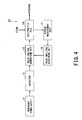
- Fig. 4 shows the hydrogen production system 10 according to a second embodiment. Note that components corresponding to those of the first embodiment are assigned same reference numerals, and an overlapping description is omitted.
- a current measurement unit 17 is connected to the electrolytic cell 14, and measures a value of a current flowing through the electrolytic cell 14.
- a pulse amplitude adjustment unit 18 changes the amplitude of the pulse voltage so as to obtain an applied voltage corresponding to a flow rate of the steam in the electrolytic cell 14 according to a change in the measured current value.
- the flow rate of the steam in the electrolytic cell 14 is determined to be in a surplus state, and the amplitude of the pulse voltage is changed to a higher voltage value. Accordingly, the electrolytic reaction is promoted corresponding to the surplus state of the steam rate.
- the flow rate of the steam in the electrolytic cell 14 is determined to be in a steam starvation state, and the amplitude of the pulse voltage is changed to a lower voltage value. Accordingly, the electrolytic reaction is inhibited corresponding to the steam starvation state.
- the function of the pulse amplitude adjustment unit 18 may also be configured so as to be implemented by executing a predetermined program code using an electronic circuit such as a processor, or without being limited to such software processing, a unit or computer implemented by hardware processing using an electronic circuit such as an ASIC or may be configured as a unit or computer implemented by combining software processing and hardware processing.
- Figs. 5A to 5C are graphs for explaining a change in the pulse voltage in association with a change in the current flowing through the electrolytic cell 14.
- a solid line indicates the pulse voltage applied to the electrolytic cell 14
- a dashed line indicates the current in the electrolytic cell 14.
- Fig. 5A is a graph illustrating a pulse voltage when the current value is proper, that is, when the steam rate in the electrolytic cell 14 is proper.
- the voltage V s where the thermoneutral point can be maintained during the electrolytic reaction is set as the amplitude of the pulse voltage.
- a current i corresponding to the applied voltage is measured in the electrolytic cell 14.
- Fig. 5B is a graph illustrating a pulse voltage when the current value is increased to i+ ⁇ i, that is, when the steam flow rate in the electrolytic cell 14 is in the surplus state.
- the electrolytic reaction is promoted by increasing the amplitude of the pulse voltage to V s + ⁇ V.
- Fig. 5C is a graph illustrating a pulse voltage when the current value is decreased to i- ⁇ i, that is, when the steam flow rate in the electrolytic cell 14 is in the steam starvation state.
- the electrolytic reaction is inhibited by decreasing the amplitude of the pulse voltage to V s - ⁇ V.
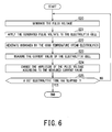
- Fig. 6 is a flowchart illustrating a control action of the hydrogen production system 10 according to the second embodiment.
- the pulse voltage generation unit 13 generates the pulse voltage having the set amplitude, cyclic period, and pulse width (S20).
- the generated pulse voltage is applied to the electrolytic cell 14, and the electrolytic cell 14 generates hydrogen by the high temperature steam electrolysis by using the steam supplied into the electrolytic cell (S21, S22).
- the current measurement unit 17 measures the current value of the electrolytic cell 14 during the electrolytic reaction in the electrolytic cell 14 (S23).
- the pulse amplitude adjustment unit 18 changes the amplitude of the pulse voltage according to the measured current value (S24).
- the electrolytic reaction is performed with the amplitude of the pulse voltage being adjusted until a set electrolytic time has elapsed (S25: NO, S20 to S24). When the electrolytic time has elapsed, the electrolytic reaction is terminated by stopping the generation of the pulse voltage (S25: YES).
- the pulse voltage is applied to the electrolytic cell 14 to perform the electrolytic reaction, and the amplitude of the pulse voltage is changed according to the change in the current in the electrolytic cell 14. Accordingly, even when the steam rate used for the electrolytic reaction varies due to the change in the supplied electric power, an efficient hydrogen production operation according to the steam rate is enabled. Since driving of the electrolytic cell 14 in the steam depleted state is suppressed, maintainability of the electrolytic cell 14 can be improved.
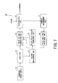
- Fig. 7 shows the hydrogen production system 10 according to a third embodiment. Note that components corresponding to those of the first embodiment ( Fig. 1 ) and those of the second embodiment ( Fig. 4 ) are assigned same reference numerals, and an overlapping description is omitted.
- the hydrogen production operation is performed by adjusting the cyclic period and the amplitude of the pulse voltage by use of the pulse cyclic period adjustment unit 16 and the pulse amplitude adjustment unit 18 during the electrolytic reaction in the electrolytic cell 14.
- the pulse amplitude adjustment unit 18 adjusts the amplitude within a range in which the thermoneutral point is maintained.
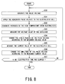
- Fig. 8 is a flowchart illustrating a control action of the hydrogen production system 10 according to the third embodiment.
- the pulse voltage generation unit 13 generates the pulse voltage having the set amplitude, cyclic period, and pulse width (S30).
- the generated pulse voltage is applied to the electrolytic cell 14, and the electrolytic cell 14 generates hydrogen by the high temperature steam electrolysis by using the steam supplied into the electrolytic cell (S31, S32).
- the voltage measurement unit 15 measures the voltage value of the capacitor 12 during the electrolytic reaction in the electrolytic cell 14 (S33).
- the pulse cyclic period adjustment unit 16 changes the cyclic period of the pulse voltage according to the measured voltage value (S34).
- the current measurement unit 17 measures the current value of the electrolytic cell 14 (S35).
- the pulse amplitude adjustment unit 18 changes the amplitude of the pulse voltage according to the measured current value (S36).
- the electrolytic reaction is performed with the cyclic period and the amplitude of the pulse voltage being adjusted until a set electrolytic time has elapsed (S37: NO, S30 to S36).
- a set electrolytic time has elapsed
- the electrolytic reaction is terminated by stopping the generation of the pulse voltage (S37: YES).
- the pulse voltage is applied to the electrolytic cell 14 to perform the electrolytic reaction, and the cyclic period and the amplitude of the pulse voltage are adjusted. Accordingly, the thermoneutral point is maintained in the electrolytic cell 14, and a more efficient hydrogen production operation according to the steam rate is enabled.
- the pulse voltage is applied to the electrolytic cell that performs the high temperature steam electrolysis, and at least one of the cyclic period and the amplitude of the pulse voltage is adjusted.
- the pulse voltage is applied to the electrolytic cell that performs the high temperature steam electrolysis, and at least one of the cyclic period and the amplitude of the pulse voltage is adjusted.
Landscapes
- Chemical & Material Sciences (AREA)
- Engineering & Computer Science (AREA)
- Chemical Kinetics & Catalysis (AREA)
- Electrochemistry (AREA)
- Materials Engineering (AREA)
- Metallurgy (AREA)
- Organic Chemistry (AREA)
- Inorganic Chemistry (AREA)
- Automation & Control Theory (AREA)
- Analytical Chemistry (AREA)
- Electrolytic Production Of Non-Metals, Compounds, Apparatuses Therefor (AREA)
Abstract
Description
- This application is based upon and claims the benefit of priority from Japanese Patent application No.
2014-162431, filed on August 8, 2014 - Embodiments of the present invention relate to a technique for producing hydrogen in which hydrogen is generated by using high temperature steam electrolysis.
- Realization of a hydrogen energy society using hydrogen as an energy medium has attracted attention. As one of technologies for producing hydrogen, a high temperature steam electrolysis is widely known. The high temperature steam electrolysis is a method in which hydrogen and oxygen are generated by electrolyzing steam with a high temperature (normally, 500°C or more).
- The method has an advantage to reduce an amount of electricity required for electrolysis by electrolyzing steam under a high temperature environment as compared to electrolysis of water. Because of the characteristic as described above, an same amount of hydrogen can be obtained by using smaller electricity than that of the room temperature water electrolysis by about 30%. Thus, hydrogen can be produced at high energy efficiency.
- Furthermore, since water is a raw material, it is possible to produce hydrogen without discharging carbon dioxide at all if electric power obtained by renewable energy that generates no carbon dioxide and a heat source that generates no carbon dioxide are used.
- In the high temperature steam electrolysis, a hydrogen electrode and an oxygen electrode are provided on both sides of a solid oxide electrolyte to constitute an electrolytic cell. High temperature steam is supplied to the hydrogen electrode side, and an electrolytic voltage is applied to the both electrodes, so that the steam is decomposed to hydrogen and oxygen.
- Conventionally, various hydrogen production apparatuses that safely and efficiently produce hydrogen by the high temperature steam electrolysis have been studied. A technology to generate hydrogen efficiently by the high temperature electrolysis with lower energy has been disclosed (for example, Japanese Patent Laid-Open Nos.
2002-348694 2005-281716 2013-49600 - In the above high temperature steam electrolysis, by performing an electrolytic reaction at a thermoneutral point at which an endothermic reaction in a process in which hydrogen and oxygen are generated from steam by the electrolytic reaction, and an exothermic reaction by electrical resistance of the electrolytic cell itself become almost equal to each other, it is possible to minimize energy input from outside, and produce hydrogen at high efficiency.
- However, when the renewable energy is used as an electric power source for the electrolytic reaction, there is a problem that it is difficult to maintain an applied voltage to the electrolytic cell around the thermoneutral point since the electric power obtained by the renewable energy varies with time.
- Also, when a time-varying electric power source is used, the electrolytic cell may be brought into a steam starvation state (steam starvation) or a surplus steam state due to a change in a steam rate used for the electrolytic reaction. Thus, there is a problem that it is difficult to perform an efficient hydrogen production operation according to the steam rate.
- To solve the above problems, it is an object of present invention to provide a technique for producing hydrogen that achieves a highly-efficient hydrogen production operation even when a time-varying electric power source is used.
- A hydrogen production system according to an embodiment of the present invention includes a capacitor inputting electric power energy from a renewable power supply, and storing electric power, a pulse voltage generation unit generating a pulse voltage having a set amplitude and a set cyclic period by using the electric power stored in the capacitor, and an electrolytic cell applying the generated pulse voltage, and generating hydrogen by high temperature steam electrolysis by using steam supplied into the electrolytic cell.
- A method for producing hydrogen according to an embodiment of the present invention includes the steps of: inputting electric power energy from a renewable power supply to store electric power in a capacitor; generating a pulse voltage having a set amplitude and a set cyclic period by using the stored electric power; and applying the generated pulse voltage to generate hydrogen by high temperature steam electrolysis in an electrolytic cell by using steam supplied into the electrolytic cell.
-
-
Fig. 1 is a configuration diagram of a hydrogen production system according to a first embodiment; -
Fig. 2A is a graph illustrating a pulse voltage applied when electric power supplied from a renewable power supply is proper,Fig. 2B is a graph illustrating a pulse voltage applied when the supplied electric power is increased, andFig. 2C is a graph illustrating a pulse voltage applied when the supplied electric power is decreased; -
Fig. 3 is a flowchart illustrating a control action of the hydrogen production system according to the first embodiment; -
Fig. 4 is a configuration diagram of a hydrogen production system according to a second embodiment; -
Fig. 5A is a graph illustrating a pulse voltage applied when a rate of steam is proper,Fig. 5B is a graph illustrating a pulse voltage applied when the rate of steam is excessive, andFig. 5C is a graph illustrating a pulse voltage applied when the steam is depleted; -
Fig. 6 is a flowchart illustrating a control action of the hydrogen production system according to the second embodiment; -
Fig. 7 is a configuration diagram of a hydrogen production system according to a third embodiment; and -
Fig. 8 is a flowchart illustrating a control action of the hydrogen production system according to the third embodiment. - Hereinafter, embodiments of the present invention are described based on the accompanying drawings.
- As shown in
Fig. 1 , ahydrogen production system 10 according to a first embodiment includes acapacitor 12, a pulsevoltage generation unit 13, and anelectrolytic cell 14. Electric power energy from arenewable power supply 11 is inputted into thecapacitor 12, and thecapacitor 12 stores electric power. The pulsevoltage generation unit 13 generates a pulse voltage having a set amplitude and a set cyclic period by using the electric power stored in thecapacitor 12. The generated pulse voltage is applied to theelectrolytic cell 14, and theelectrolytic cell 14 generates hydrogen by high temperature steam electrolysis by using steam supplied into the electrolytic cell. - The
hydrogen production system 10 further includes avoltage measurement unit 15 and a pulse cyclicperiod adjustment unit 16. Thevoltage measurement unit 15 measures a voltage value of thecapacitor 12. The pulse cyclicperiod adjustment unit 16 changes the cyclic period of the pulse voltage according to a change in the measured voltage value. - The
renewable power supply 11 means an electric power source using renewable energy such as wind power, hydraulic power, and solar power. The electric power energy outputted from therenewable power supply 11 has a characteristic to change with passage of time. - The electric power energy outputted from the
renewable power supply 11 is inputted into thecapacitor 12, and thecapacitor 12 stores the electric power. Thecapacitor 12 can be advantageously used for storing the electric power energy since thecapacitor 12 is less deteriorated by repetitive use (charging and discharging), and has faster load following capability as compared to a case in which a chemical battery such as a lead-acid battery is used for storing the electric power energy. It is also possible to instantly measure the voltage value at thevoltage measurement unit 15. - The electric power stored in the
capacitor 12 is inputted into the pulsevoltage generation unit 13, and the pulsevoltage generation unit 13 generates the pulse voltage having a set amplitude, a set cyclic period, and a set pulse width. Note that a voltage where a thermoneutral point can be maintained during an electrolytic reaction is previously set as the amplitude in the pulsevoltage generation unit 13. The cyclic period and the pulse width are set based on a relationship between the amplitude and electric power required for properly operating theelectrolytic cell 14. - In the
electrolytic cell 14, a solid oxide electrolyte (not shown) is arranged in a center, and a hydrogen electrode and an oxygen electrode are formed on both sides of the solid oxide electrolyte. - The pulse voltage generated in the pulse
voltage generation unit 13 is applied to theelectrolytic cell 14, and theelectrolytic cell 14 generates hydrogen and oxygen by the high temperature steam electrolysis by using the steam supplied into the electrolytic cell. - The
voltage measurement unit 15 measures a voltage of the electric power stored in thecapacitor 12 during the electrolytic reaction in theelectrolytic cell 14. Accordingly, the change in the electric power supplied from therenewable power supply 11 is monitored. - The pulse cyclic
period adjustment unit 16 changes the cyclic period of the pulse voltage according to the change in the measured voltage value. - To be more specific, when the measured voltage value is increased, that is, when the electric power supplied from the
renewable power supply 11 is increased, the amplitude of the pulse voltage is maintained constant, and the cyclic period of the pulse voltage set in the pulsevoltage generation unit 13 is changed to a shorter period. Accordingly, with average electric power consumed in theelectrolytic cell 14 being increased, the electrolytic reaction in theelectrolytic cell 14 is maintained at the thermoneutral point. - On the other hand, when the measured voltage value is decreased, that is, when the electric power supplied from the
renewable power supply 11 is decreased, the amplitude of the pulse voltage is maintained constant, and the cyclic period of the pulse voltage set in the pulsevoltage generation unit 13 is changed to a longer period. Accordingly, with the average electric power being decreased, the electrolytic reaction in theelectrolytic cell 14 is maintained at the thermoneutral point. - The function of the pulse cyclic
period adjustment unit 16 may also be configured so as to be implemented by executing a predetermined program code using an electronic circuit such as a processor, or without being limited to such software processing, a unit or computer implemented by hardware processing using an electronic circuit such as an ASIC or may be configured as a unit or computer implemented by combining software processing and hardware processing. -
Figs. 2A to 2C are graphs for explaining a change in the pulse voltage in association with a change in the electric power supplied from therenewable power supply 11. In the graphs, a solid line indicates the pulse voltage applied to theelectrolytic cell 14, and a dashed line indicates the average electric power consumed in theelectrolytic cell 14. -
Fig. 2A is a graph illustrating a pulse voltage when the electric power supplied from therenewable power supply 11 is proper. A voltage Vs where the thermoneutral point can be maintained during the electrolytic reaction is set as the amplitude of the pulse voltage. A cyclic period Ts and a pulse width Tw are set based on a relationship between the voltage Vs and the electric power required for properly operating theelectrolytic cell 14. -
Fig. 2B is a graph illustrating a pulse voltage when the electric power supplied from therenewable power supply 11 is increased. The amplitude of the pulse voltage is maintained constant at the voltage Vs, and the cyclic period of the pulse voltage is changed to Ts1. Accordingly, the average electric power consumed in theelectrolytic cell 14 is increased. -
Fig. 2C is a graph illustrating a pulse voltage when the electric power supplied from therenewable power supply 11 is decreased. The amplitude of the pulse voltage is maintained constant at the voltage Vs, and the cyclic period of the pulse voltage is changed to Ts2. Accordingly, the average electric power consumed in theelectrolytic cell 14 is decreased. -
Fig. 3 is a flowchart illustrating a control action of thehydrogen production system 10 according to the first embodiment (seeFig. 1 as appropriate). - The pulse
voltage generation unit 13 generates the pulse voltage having the set amplitude, cyclic period, and pulse width (S10). - The generated pulse voltage is applied to the
electrolytic cell 14, and theelectrolytic cell 14 generates hydrogen by the high temperature steam electrolysis by using the steam supplied into the electrolytic cell (S11, S12). - The
voltage measurement unit 15 measures the voltage value of thecapacitor 12 during the electrolytic reaction in the electrolytic cell 14 (S13). - The pulse cyclic
period adjustment unit 16 changes the cyclic period of the pulse voltage according to the measured voltage value (S14). - The electrolytic reaction is performed with the cyclic period of the pulse voltage being adjusted until a set electrolytic time has elapsed (S15: NO, S10 to S14). When the electrolytic time has elapsed, the electrolytic reaction is terminated by stopping the generation of the pulse voltage (S15: YES).
- As described above, the pulse voltage is applied to the
electrolytic cell 14 to perform the electrolytic reaction, and the cyclic period of the pulse voltage is changed according to the change in the electric power supplied from therenewable power supply 11. Accordingly, even when the supplied electric power changes with time, the applied voltage required for maintaining the thermoneutral point in theelectrolytic cell 14 can be held. It is thus possible to perform a highly-efficient hydrogen production operation. -
Fig. 4 shows thehydrogen production system 10 according to a second embodiment. Note that components corresponding to those of the first embodiment are assigned same reference numerals, and an overlapping description is omitted. - A
current measurement unit 17 is connected to theelectrolytic cell 14, and measures a value of a current flowing through theelectrolytic cell 14. - A pulse
amplitude adjustment unit 18 changes the amplitude of the pulse voltage so as to obtain an applied voltage corresponding to a flow rate of the steam in theelectrolytic cell 14 according to a change in the measured current value. - To be more specific, when the measured current value is higher than a current value required for properly operating the
electrolytic cell 14, the flow rate of the steam in theelectrolytic cell 14 is determined to be in a surplus state, and the amplitude of the pulse voltage is changed to a higher voltage value. Accordingly, the electrolytic reaction is promoted corresponding to the surplus state of the steam rate. - On the other hand, when the measured current value is lower than the proper value, the flow rate of the steam in the
electrolytic cell 14 is determined to be in a steam starvation state, and the amplitude of the pulse voltage is changed to a lower voltage value. Accordingly, the electrolytic reaction is inhibited corresponding to the steam starvation state. - The function of the pulse
amplitude adjustment unit 18 may also be configured so as to be implemented by executing a predetermined program code using an electronic circuit such as a processor, or without being limited to such software processing, a unit or computer implemented by hardware processing using an electronic circuit such as an ASIC or may be configured as a unit or computer implemented by combining software processing and hardware processing. -
Figs. 5A to 5C are graphs for explaining a change in the pulse voltage in association with a change in the current flowing through theelectrolytic cell 14. In the graphs, a solid line indicates the pulse voltage applied to theelectrolytic cell 14, and a dashed line indicates the current in theelectrolytic cell 14. -
Fig. 5A is a graph illustrating a pulse voltage when the current value is proper, that is, when the steam rate in theelectrolytic cell 14 is proper. The voltage Vs where the thermoneutral point can be maintained during the electrolytic reaction is set as the amplitude of the pulse voltage. A current i corresponding to the applied voltage is measured in theelectrolytic cell 14. -
Fig. 5B is a graph illustrating a pulse voltage when the current value is increased to i+Δi, that is, when the steam flow rate in theelectrolytic cell 14 is in the surplus state. In this case, the electrolytic reaction is promoted by increasing the amplitude of the pulse voltage to Vs+ΔV. -
Fig. 5C is a graph illustrating a pulse voltage when the current value is decreased to i-Δi, that is, when the steam flow rate in theelectrolytic cell 14 is in the steam starvation state. In this case, the electrolytic reaction is inhibited by decreasing the amplitude of the pulse voltage to Vs-ΔV. -
Fig. 6 is a flowchart illustrating a control action of thehydrogen production system 10 according to the second embodiment. - The pulse
voltage generation unit 13 generates the pulse voltage having the set amplitude, cyclic period, and pulse width (S20). - The generated pulse voltage is applied to the
electrolytic cell 14, and theelectrolytic cell 14 generates hydrogen by the high temperature steam electrolysis by using the steam supplied into the electrolytic cell (S21, S22). - The
current measurement unit 17 measures the current value of theelectrolytic cell 14 during the electrolytic reaction in the electrolytic cell 14 (S23). - The pulse
amplitude adjustment unit 18 changes the amplitude of the pulse voltage according to the measured current value (S24). - The electrolytic reaction is performed with the amplitude of the pulse voltage being adjusted until a set electrolytic time has elapsed (S25: NO, S20 to S24). When the electrolytic time has elapsed, the electrolytic reaction is terminated by stopping the generation of the pulse voltage (S25: YES).
- As described above, the pulse voltage is applied to the
electrolytic cell 14 to perform the electrolytic reaction, and the amplitude of the pulse voltage is changed according to the change in the current in theelectrolytic cell 14. Accordingly, even when the steam rate used for the electrolytic reaction varies due to the change in the supplied electric power, an efficient hydrogen production operation according to the steam rate is enabled. Since driving of theelectrolytic cell 14 in the steam depleted state is suppressed, maintainability of theelectrolytic cell 14 can be improved. -
Fig. 7 shows thehydrogen production system 10 according to a third embodiment. Note that components corresponding to those of the first embodiment (Fig. 1 ) and those of the second embodiment (Fig. 4 ) are assigned same reference numerals, and an overlapping description is omitted. - In the third embodiment, the hydrogen production operation is performed by adjusting the cyclic period and the amplitude of the pulse voltage by use of the pulse cyclic
period adjustment unit 16 and the pulseamplitude adjustment unit 18 during the electrolytic reaction in theelectrolytic cell 14. Note that the pulseamplitude adjustment unit 18 adjusts the amplitude within a range in which the thermoneutral point is maintained. -
Fig. 8 is a flowchart illustrating a control action of thehydrogen production system 10 according to the third embodiment. - The pulse
voltage generation unit 13 generates the pulse voltage having the set amplitude, cyclic period, and pulse width (S30). - The generated pulse voltage is applied to the
electrolytic cell 14, and theelectrolytic cell 14 generates hydrogen by the high temperature steam electrolysis by using the steam supplied into the electrolytic cell (S31, S32). - The
voltage measurement unit 15 measures the voltage value of thecapacitor 12 during the electrolytic reaction in the electrolytic cell 14 (S33). - The pulse cyclic
period adjustment unit 16 changes the cyclic period of the pulse voltage according to the measured voltage value (S34). - The
current measurement unit 17 measures the current value of the electrolytic cell 14 (S35). - The pulse
amplitude adjustment unit 18 changes the amplitude of the pulse voltage according to the measured current value (S36). - The electrolytic reaction is performed with the cyclic period and the amplitude of the pulse voltage being adjusted until a set electrolytic time has elapsed (S37: NO, S30 to S36). When the electrolytic time has elapsed, the electrolytic reaction is terminated by stopping the generation of the pulse voltage (S37: YES).
- As described above, the pulse voltage is applied to the
electrolytic cell 14 to perform the electrolytic reaction, and the cyclic period and the amplitude of the pulse voltage are adjusted. Accordingly, the thermoneutral point is maintained in theelectrolytic cell 14, and a more efficient hydrogen production operation according to the steam rate is enabled. - In accordance with the hydrogen production system of the aforementioned respective embodiments, the pulse voltage is applied to the electrolytic cell that performs the high temperature steam electrolysis, and at least one of the cyclic period and the amplitude of the pulse voltage is adjusted. Thus, even when a time-varying electric power source is used, it is possible to achieve the highly-efficient hydrogen production operation.
- The embodiments of the present invention have thus been described. However, the embodiments have been presented as examples, which are not intended to limit the scope of the invention. The novel embodiments can be implemented in various other modes. Various omissions, replacements, and changes may be made within the scope without departing from the gist of the invention. The embodiments and modifications are encompassed by the scope and gist of the invention, and included in the invention described in claims and the equivalent scope thereof.
Claims (8)
- A hydrogen production system comprising:a capacitor inputting electric power energy from a renewable power supply , and storing electric power;a pulse voltage generation unit generating a pulse voltage having a set amplitude and a set cyclic period by using the electric power stored in the capacitor; andan electrolytic cell applying the generated pulse voltage, and generating hydrogen by high temperature steam electrolysis by using steam supplied into the electrolytic cell.
- The hydrogen production system according to claim 1, further comprising:a voltage measurement unit measuring a voltage value of the capacitor; anda pulse cyclic period adjustment unit changing the cyclic period of the pulse voltage according to a change in the measured voltage value.
- The hydrogen production system according to claim 1, further comprising:a current measurement unit measuring a value of a current flowing through the electrolytic cell; anda pulse amplitude adjustment unit changing the amplitude of the pulse voltage according to a change in the measured current value.
- A hydrogen production system comprising:a capacitor inputting electric power energy from a renewable power supply , and storing electric power;a pulse voltage generation unit generating a pulse voltage having a set amplitude and a set cyclic period by using the electric power stored in the capacitor;an electrolytic cell applying the generated pulse voltage, and generating hydrogen by high temperature steam electrolysis by using steam supplied into the electrolytic cell;a voltage measurement unit measuring a voltage value of the capacitor;a pulse cyclic period adjustment unit changing the cyclic period of the pulse voltage according to a change in the measured voltage value;a current measurement unit measuring a value of a current flowing through the electrolytic cell; anda pulse amplitude adjustment unit changing the amplitude of the pulse voltage according to a change in the measured current value.
- A method for producing hydrogen comprising the steps of:inputting electric power energy from a renewable power supply to store electric power in a capacitor;generating a pulse voltage having a set amplitude and a set cyclic period by using the stored electric power; andapplying the generated pulse voltage to generate hydrogen by high temperature steam electrolysis in an electrolytic cell by using steam supplied into the electrolytic cell.
- The method for producing hydrogen according to claim 5, further comprising the steps of:measuring a voltage value of the capacitor; andchanging the cyclic period of the pulse voltage according to a change in the measured voltage value.
- The method for producing hydrogen according to claim 5, further comprising the steps of:measuring a value of a current flowing through the electrolytic cell; andchanging the amplitude of the pulse voltage according to a change in the measured current value.
- A method for producing hydrogen comprising the steps of:inputting electric power energy from a renewable power supply to store electric power in a capacitor;generating a pulse voltage having a set amplitude and a set cyclic period by using the stored electric power;applying the generated pulse voltage to generate hydrogen by high temperature steam electrolysis in an electrolytic cell by using steam supplied into the electrolytic cell;measuring a voltage value of the capacitor;changing the cyclic period of the pulse voltage according to a change in the measured voltage value;measuring a value of a current flowing through the electrolytic cell; andchanging the amplitude of the pulse voltage according to a change in the measured current value.
Applications Claiming Priority (1)
| Application Number | Priority Date | Filing Date | Title |
|---|---|---|---|
| JP2014162431A JP6363425B2 (en) | 2014-08-08 | 2014-08-08 | Hydrogen production system and hydrogen production method |
Publications (2)
| Publication Number | Publication Date |
|---|---|
| EP2982778A1 true EP2982778A1 (en) | 2016-02-10 |
| EP2982778B1 EP2982778B1 (en) | 2018-01-03 |
Family
ID=53765154
Family Applications (1)
| Application Number | Title | Priority Date | Filing Date |
|---|---|---|---|
| EP15179251.2A Active EP2982778B1 (en) | 2014-08-08 | 2015-07-31 | Hydrogen production system and method for producing hydrogen |
Country Status (6)
| Country | Link |
|---|---|
| US (1) | US10081872B2 (en) |
| EP (1) | EP2982778B1 (en) |
| JP (1) | JP6363425B2 (en) |
| AR (1) | AR102329A1 (en) |
| CA (1) | CA2899581C (en) |
| DK (1) | DK2982778T3 (en) |
Cited By (1)
| Publication number | Priority date | Publication date | Assignee | Title |
|---|---|---|---|---|
| WO2016087239A1 (en) * | 2014-12-01 | 2016-06-09 | Commissariat à l'Energie Atomique et aux Energies Alternatives | High-temperature steam electrolyser |
Families Citing this family (15)
| Publication number | Priority date | Publication date | Assignee | Title |
|---|---|---|---|---|
| CN105594016A (en) | 2013-07-31 | 2016-05-18 | 奥克海德莱克斯控股有限公司 | Composite three-dimensional electrode and manufacturing method |
| WO2017100847A1 (en) * | 2015-12-14 | 2017-06-22 | Aquahydrex Pty Ltd | Electrochemical cell and components thereof capable of operating at high current density |
| JP6704998B2 (en) * | 2016-08-18 | 2020-06-03 | 株式会社東芝 | Hydrogen production system and method for controlling electrolytic cell stack |
| JP7110042B2 (en) * | 2018-09-13 | 2022-08-01 | 東芝エネルギーシステムズ株式会社 | Hydrogen production device and hydrogen production method |
| KR20210122260A (en) | 2019-02-01 | 2021-10-08 | 아쿠아하이드렉스, 인크. | Electrochemical systems with limited electrolytes |
| JP7039504B2 (en) * | 2019-02-08 | 2022-03-22 | 東芝エネルギーシステムズ株式会社 | Control device and control method for hydrogen production plant |
| EP3719171A1 (en) * | 2019-04-05 | 2020-10-07 | DynElectro ApS | Electrolysis system with controlled thermal profile |
| EP3725917A1 (en) * | 2019-04-17 | 2020-10-21 | SunFire GmbH | Solid oxide cell (soc) operation method and solid oxide cell (soc) assembly |
| DE102021200029A1 (en) * | 2020-01-10 | 2021-07-15 | Sms Group Gmbh | Process for the production of hydrogen and oxygen by means of an electrolyzer |
| EP4027419B1 (en) * | 2021-01-12 | 2024-03-27 | DynElectro ApS | Power converter systems for electrolysis stacks |
| JP7646464B2 (en) * | 2021-06-08 | 2025-03-17 | 東芝エネルギーシステムズ株式会社 | Hydrogen production device and hydrogen production method |
| JP7848306B2 (en) * | 2021-07-21 | 2026-04-20 | コンヴィオン オサケユキチュア | Apparatus and method for electrolytic power conversion |
| CN115094482B (en) * | 2022-07-05 | 2024-09-27 | 浙江大学 | A control method for producing hydrogen by electrolysis of alkaline solution adapting to wide power fluctuations |
| JP2025165154A (en) * | 2024-04-22 | 2025-11-04 | 三菱重工業株式会社 | Fuel production system and fuel production method |
| CN120330802A (en) * | 2025-06-09 | 2025-07-18 | 国孚新能源有限公司 | A pulse current control method for producing hydrogen by electrolysis of water |
Citations (7)
| Publication number | Priority date | Publication date | Assignee | Title |
|---|---|---|---|---|
| US4798661A (en) * | 1985-03-25 | 1989-01-17 | Meyer Stanley A | Gas generator voltage control circuit |
| WO1995032321A1 (en) * | 1994-05-24 | 1995-11-30 | Aquagas New Zealand Limited | Electrolytic cell control method and apparatus |
| JP2002348694A (en) | 2001-05-23 | 2002-12-04 | Yukio Wakahata | Energy supply system |
| JP2005281716A (en) | 2004-03-26 | 2005-10-13 | Tadahiko Mizuno | Electrolytic light-emitting device, electrode for electrolytic light-emitting device, hydrogen-gas-generating apparatus, power generator, cogeneration system, method for generating hydrogen gas, method for generating power and method for supplying energy |
| US20090315330A1 (en) * | 2008-06-20 | 2009-12-24 | Dederick Robert J | Facility for refueling of clean air vehicles/marine craft and generation and storage of power |
| JP2013049600A (en) | 2011-08-31 | 2013-03-14 | Hitachi Ltd | Regenerable energy storage system |
| US8709221B1 (en) * | 2010-02-24 | 2014-04-29 | Andrew L. Smith | Current regulator for mobile water electrolyzer |
Family Cites Families (12)
| Publication number | Priority date | Publication date | Assignee | Title |
|---|---|---|---|---|
| JPS54111502A (en) * | 1978-02-20 | 1979-08-31 | Inoue Japax Res Inc | Gas evolution by electrolysis of water |
| JPH07233493A (en) * | 1994-02-22 | 1995-09-05 | Mitsubishi Heavy Ind Ltd | Electric power converter for water electrolyzing system |
| US6126794A (en) * | 1998-06-26 | 2000-10-03 | Xogen Power Inc. | Apparatus for producing orthohydrogen and/or parahydrogen |
| US20030066750A1 (en) * | 2001-10-04 | 2003-04-10 | Wu Arthur Cheng-Hsin | Electrolytic combustion |
| US6984295B2 (en) * | 2002-02-06 | 2006-01-10 | Luxon Energy Devices Corporation | Electrolytic cell for ozone generation |
| JP4679850B2 (en) * | 2004-07-30 | 2011-05-11 | 日本碍子株式会社 | Method and apparatus for producing substance by pulse electrolysis |
| JP2007249341A (en) * | 2006-03-14 | 2007-09-27 | Hitachi Ltd | Hydrogen production system |
| JP2010280975A (en) * | 2009-06-05 | 2010-12-16 | Mitsubishi Heavy Ind Ltd | Water electrolysis system and hydrogen utilization system |
| JP2013501142A (en) * | 2009-08-03 | 2013-01-10 | クラフト ホールディングス ダブリュエイ プロプライエタリー リミテッド | Electrolytic cell and power unit incorporating electrolytic cell |
| US9028781B2 (en) | 2010-12-03 | 2015-05-12 | Hitachi, Ltd. | Renewable energy storage system |
| FR2981368B1 (en) * | 2011-10-12 | 2013-11-15 | Areva | PROCESS FOR GENERATING HYDROGEN AND OXYGEN BY ELECTROLYSIS OF WATER VAPOR |
| JP5711687B2 (en) * | 2012-03-23 | 2015-05-07 | 東京瓦斯株式会社 | Electrochemical device and power storage system |
-
2014
- 2014-08-08 JP JP2014162431A patent/JP6363425B2/en active Active
-
2015
- 2015-07-31 EP EP15179251.2A patent/EP2982778B1/en active Active
- 2015-07-31 DK DK15179251.2T patent/DK2982778T3/en active
- 2015-08-03 US US14/816,455 patent/US10081872B2/en active Active
- 2015-08-04 CA CA2899581A patent/CA2899581C/en active Active
- 2015-08-06 AR ARP150102523A patent/AR102329A1/en active IP Right Grant
Patent Citations (7)
| Publication number | Priority date | Publication date | Assignee | Title |
|---|---|---|---|---|
| US4798661A (en) * | 1985-03-25 | 1989-01-17 | Meyer Stanley A | Gas generator voltage control circuit |
| WO1995032321A1 (en) * | 1994-05-24 | 1995-11-30 | Aquagas New Zealand Limited | Electrolytic cell control method and apparatus |
| JP2002348694A (en) | 2001-05-23 | 2002-12-04 | Yukio Wakahata | Energy supply system |
| JP2005281716A (en) | 2004-03-26 | 2005-10-13 | Tadahiko Mizuno | Electrolytic light-emitting device, electrode for electrolytic light-emitting device, hydrogen-gas-generating apparatus, power generator, cogeneration system, method for generating hydrogen gas, method for generating power and method for supplying energy |
| US20090315330A1 (en) * | 2008-06-20 | 2009-12-24 | Dederick Robert J | Facility for refueling of clean air vehicles/marine craft and generation and storage of power |
| US8709221B1 (en) * | 2010-02-24 | 2014-04-29 | Andrew L. Smith | Current regulator for mobile water electrolyzer |
| JP2013049600A (en) | 2011-08-31 | 2013-03-14 | Hitachi Ltd | Regenerable energy storage system |
Cited By (1)
| Publication number | Priority date | Publication date | Assignee | Title |
|---|---|---|---|---|
| WO2016087239A1 (en) * | 2014-12-01 | 2016-06-09 | Commissariat à l'Energie Atomique et aux Energies Alternatives | High-temperature steam electrolyser |
Also Published As
| Publication number | Publication date |
|---|---|
| EP2982778B1 (en) | 2018-01-03 |
| CA2899581C (en) | 2018-01-23 |
| AR102329A1 (en) | 2017-02-22 |
| JP6363425B2 (en) | 2018-07-25 |
| US10081872B2 (en) | 2018-09-25 |
| JP2016037643A (en) | 2016-03-22 |
| DK2982778T3 (en) | 2018-03-26 |
| US20160040310A1 (en) | 2016-02-11 |
| CA2899581A1 (en) | 2016-02-08 |
Similar Documents
| Publication | Publication Date | Title |
|---|---|---|
| EP2982778B1 (en) | Hydrogen production system and method for producing hydrogen | |
| KR102444737B1 (en) | DC bus control system | |
| EP3719171A1 (en) | Electrolysis system with controlled thermal profile | |
| JP4791689B2 (en) | Power supply | |
| JP6574891B2 (en) | Hydrogen production system and hydrogen production method | |
| JP5731241B2 (en) | Power supply system | |
| KR20170129456A (en) | Battery energy storage system | |
| Ereli et al. | First pulsed control system design for enhanced hydrogen production performance in proton exchange membrane water electrolyzers | |
| KR101887787B1 (en) | Apparatus and method for generating alternating current for diagnosing fuel cell stack | |
| JP5605437B2 (en) | Fuel production system | |
| JP2015164028A (en) | Electrolytic system using photovoltaic power generation | |
| JP2019121424A (en) | Control device for secondary battery, secondary battery device, uninterruptible power supply device, power supply system, and method | |
| Lee et al. | Characterization of MnO2 positive electrode for fuel cell/battery (FCB) | |
| CN104733752A (en) | Method and device for generating charging current for fuel cell stack | |
| JP6826476B2 (en) | Water electrolysis system | |
| JP7789637B2 (en) | Control device for hydrogen production device, hydrogen production facility, control method for hydrogen production device, and control program for hydrogen production device | |
| CA2621600A1 (en) | Hydrogen generating apparatus and fuel cell power generation system controlling amount of hydrogen generation | |
| US20220389598A1 (en) | Hydrogen production apparatus and hydrogen production method | |
| KR20170078907A (en) | Hybrid Electricity Supplying Device Containing Solid Oxide Fuel Cell and Secondary Battery | |
| KR101394870B1 (en) | Method for controlling generating power of fuel cell | |
| RU2560883C1 (en) | Method of operating solid-polymer water electrolyser | |
| RU2554876C1 (en) | Method for using solid-polymer electrolytic cell | |
| CN110678580B (en) | Hydrogen generator and hydrogen generating method | |
| KR101787565B1 (en) | Operation Method For MCFC System | |
| JP2019026857A (en) | Electrolysis system and power control method for electrolysis system |
Legal Events
| Date | Code | Title | Description |
|---|---|---|---|
| PUAI | Public reference made under article 153(3) epc to a published international application that has entered the european phase |
Free format text: ORIGINAL CODE: 0009012 |
|
| 17P | Request for examination filed |
Effective date: 20150731 |
|
| AK | Designated contracting states |
Kind code of ref document: A1 Designated state(s): AL AT BE BG CH CY CZ DE DK EE ES FI FR GB GR HR HU IE IS IT LI LT LU LV MC MK MT NL NO PL PT RO RS SE SI SK SM TR |
|
| AX | Request for extension of the european patent |
Extension state: BA ME |
|
| STAA | Information on the status of an ep patent application or granted ep patent |
Free format text: STATUS: EXAMINATION IS IN PROGRESS |
|
| 17Q | First examination report despatched |
Effective date: 20161220 |
|
| GRAP | Despatch of communication of intention to grant a patent |
Free format text: ORIGINAL CODE: EPIDOSNIGR1 |
|
| STAA | Information on the status of an ep patent application or granted ep patent |
Free format text: STATUS: GRANT OF PATENT IS INTENDED |
|
| RIC1 | Information provided on ipc code assigned before grant |
Ipc: C25B 1/02 20060101ALI20170630BHEP Ipc: C25B 1/04 20060101ALI20170630BHEP Ipc: C25B 15/02 20060101AFI20170630BHEP |
|
| INTG | Intention to grant announced |
Effective date: 20170801 |
|
| GRAS | Grant fee paid |
Free format text: ORIGINAL CODE: EPIDOSNIGR3 |
|
| GRAA | (expected) grant |
Free format text: ORIGINAL CODE: 0009210 |
|
| STAA | Information on the status of an ep patent application or granted ep patent |
Free format text: STATUS: THE PATENT HAS BEEN GRANTED |
|
| AK | Designated contracting states |
Kind code of ref document: B1 Designated state(s): AL AT BE BG CH CY CZ DE DK EE ES FI FR GB GR HR HU IE IS IT LI LT LU LV MC MK MT NL NO PL PT RO RS SE SI SK SM TR |
|
| REG | Reference to a national code |
Ref country code: GB Ref legal event code: FG4D |
|
| REG | Reference to a national code |
Ref country code: CH Ref legal event code: EP Ref country code: AT Ref legal event code: REF Ref document number: 960352 Country of ref document: AT Kind code of ref document: T Effective date: 20180115 |
|
| REG | Reference to a national code |
Ref country code: IE Ref legal event code: FG4D |
|
| REG | Reference to a national code |
Ref country code: DE Ref legal event code: R096 Ref document number: 602015007122 Country of ref document: DE |
|
| REG | Reference to a national code |
Ref country code: DK Ref legal event code: T3 Effective date: 20180321 |
|
| REG | Reference to a national code |
Ref country code: NL Ref legal event code: MP Effective date: 20180103 |
|
| REG | Reference to a national code |
Ref country code: LT Ref legal event code: MG4D |
|
| REG | Reference to a national code |
Ref country code: FR Ref legal event code: PLFP Year of fee payment: 4 |
|
| REG | Reference to a national code |
Ref country code: AT Ref legal event code: MK05 Ref document number: 960352 Country of ref document: AT Kind code of ref document: T Effective date: 20180103 |
|
| PG25 | Lapsed in a contracting state [announced via postgrant information from national office to epo] |
Ref country code: NL Free format text: LAPSE BECAUSE OF FAILURE TO SUBMIT A TRANSLATION OF THE DESCRIPTION OR TO PAY THE FEE WITHIN THE PRESCRIBED TIME-LIMIT Effective date: 20180103 |
|
| PG25 | Lapsed in a contracting state [announced via postgrant information from national office to epo] |
Ref country code: NO Free format text: LAPSE BECAUSE OF FAILURE TO SUBMIT A TRANSLATION OF THE DESCRIPTION OR TO PAY THE FEE WITHIN THE PRESCRIBED TIME-LIMIT Effective date: 20180403 Ref country code: FI Free format text: LAPSE BECAUSE OF FAILURE TO SUBMIT A TRANSLATION OF THE DESCRIPTION OR TO PAY THE FEE WITHIN THE PRESCRIBED TIME-LIMIT Effective date: 20180103 Ref country code: LT Free format text: LAPSE BECAUSE OF FAILURE TO SUBMIT A TRANSLATION OF THE DESCRIPTION OR TO PAY THE FEE WITHIN THE PRESCRIBED TIME-LIMIT Effective date: 20180103 Ref country code: CY Free format text: LAPSE BECAUSE OF FAILURE TO SUBMIT A TRANSLATION OF THE DESCRIPTION OR TO PAY THE FEE WITHIN THE PRESCRIBED TIME-LIMIT Effective date: 20180103 Ref country code: ES Free format text: LAPSE BECAUSE OF FAILURE TO SUBMIT A TRANSLATION OF THE DESCRIPTION OR TO PAY THE FEE WITHIN THE PRESCRIBED TIME-LIMIT Effective date: 20180103 Ref country code: HR Free format text: LAPSE BECAUSE OF FAILURE TO SUBMIT A TRANSLATION OF THE DESCRIPTION OR TO PAY THE FEE WITHIN THE PRESCRIBED TIME-LIMIT Effective date: 20180103 |
|
| PG25 | Lapsed in a contracting state [announced via postgrant information from national office to epo] |
Ref country code: RS Free format text: LAPSE BECAUSE OF FAILURE TO SUBMIT A TRANSLATION OF THE DESCRIPTION OR TO PAY THE FEE WITHIN THE PRESCRIBED TIME-LIMIT Effective date: 20180103 Ref country code: BG Free format text: LAPSE BECAUSE OF FAILURE TO SUBMIT A TRANSLATION OF THE DESCRIPTION OR TO PAY THE FEE WITHIN THE PRESCRIBED TIME-LIMIT Effective date: 20180403 Ref country code: PL Free format text: LAPSE BECAUSE OF FAILURE TO SUBMIT A TRANSLATION OF THE DESCRIPTION OR TO PAY THE FEE WITHIN THE PRESCRIBED TIME-LIMIT Effective date: 20180103 Ref country code: AT Free format text: LAPSE BECAUSE OF FAILURE TO SUBMIT A TRANSLATION OF THE DESCRIPTION OR TO PAY THE FEE WITHIN THE PRESCRIBED TIME-LIMIT Effective date: 20180103 Ref country code: LV Free format text: LAPSE BECAUSE OF FAILURE TO SUBMIT A TRANSLATION OF THE DESCRIPTION OR TO PAY THE FEE WITHIN THE PRESCRIBED TIME-LIMIT Effective date: 20180103 Ref country code: GR Free format text: LAPSE BECAUSE OF FAILURE TO SUBMIT A TRANSLATION OF THE DESCRIPTION OR TO PAY THE FEE WITHIN THE PRESCRIBED TIME-LIMIT Effective date: 20180404 Ref country code: IS Free format text: LAPSE BECAUSE OF FAILURE TO SUBMIT A TRANSLATION OF THE DESCRIPTION OR TO PAY THE FEE WITHIN THE PRESCRIBED TIME-LIMIT Effective date: 20180503 Ref country code: SE Free format text: LAPSE BECAUSE OF FAILURE TO SUBMIT A TRANSLATION OF THE DESCRIPTION OR TO PAY THE FEE WITHIN THE PRESCRIBED TIME-LIMIT Effective date: 20180103 |
|
| REG | Reference to a national code |
Ref country code: DE Ref legal event code: R097 Ref document number: 602015007122 Country of ref document: DE |
|
| PG25 | Lapsed in a contracting state [announced via postgrant information from national office to epo] |
Ref country code: AL Free format text: LAPSE BECAUSE OF FAILURE TO SUBMIT A TRANSLATION OF THE DESCRIPTION OR TO PAY THE FEE WITHIN THE PRESCRIBED TIME-LIMIT Effective date: 20180103 Ref country code: RO Free format text: LAPSE BECAUSE OF FAILURE TO SUBMIT A TRANSLATION OF THE DESCRIPTION OR TO PAY THE FEE WITHIN THE PRESCRIBED TIME-LIMIT Effective date: 20180103 Ref country code: EE Free format text: LAPSE BECAUSE OF FAILURE TO SUBMIT A TRANSLATION OF THE DESCRIPTION OR TO PAY THE FEE WITHIN THE PRESCRIBED TIME-LIMIT Effective date: 20180103 |
|
| PLBE | No opposition filed within time limit |
Free format text: ORIGINAL CODE: 0009261 |
|
| STAA | Information on the status of an ep patent application or granted ep patent |
Free format text: STATUS: NO OPPOSITION FILED WITHIN TIME LIMIT |
|
| PG25 | Lapsed in a contracting state [announced via postgrant information from national office to epo] |
Ref country code: SK Free format text: LAPSE BECAUSE OF FAILURE TO SUBMIT A TRANSLATION OF THE DESCRIPTION OR TO PAY THE FEE WITHIN THE PRESCRIBED TIME-LIMIT Effective date: 20180103 Ref country code: CZ Free format text: LAPSE BECAUSE OF FAILURE TO SUBMIT A TRANSLATION OF THE DESCRIPTION OR TO PAY THE FEE WITHIN THE PRESCRIBED TIME-LIMIT Effective date: 20180103 Ref country code: SM Free format text: LAPSE BECAUSE OF FAILURE TO SUBMIT A TRANSLATION OF THE DESCRIPTION OR TO PAY THE FEE WITHIN THE PRESCRIBED TIME-LIMIT Effective date: 20180103 |
|
| 26N | No opposition filed |
Effective date: 20181005 |
|
| PG25 | Lapsed in a contracting state [announced via postgrant information from national office to epo] |
Ref country code: SI Free format text: LAPSE BECAUSE OF FAILURE TO SUBMIT A TRANSLATION OF THE DESCRIPTION OR TO PAY THE FEE WITHIN THE PRESCRIBED TIME-LIMIT Effective date: 20180103 |
|
| REG | Reference to a national code |
Ref country code: CH Ref legal event code: PL |
|
| PG25 | Lapsed in a contracting state [announced via postgrant information from national office to epo] |
Ref country code: LU Free format text: LAPSE BECAUSE OF NON-PAYMENT OF DUE FEES Effective date: 20180731 Ref country code: MC Free format text: LAPSE BECAUSE OF FAILURE TO SUBMIT A TRANSLATION OF THE DESCRIPTION OR TO PAY THE FEE WITHIN THE PRESCRIBED TIME-LIMIT Effective date: 20180103 |
|
| REG | Reference to a national code |
Ref country code: BE Ref legal event code: MM Effective date: 20180731 |
|
| PG25 | Lapsed in a contracting state [announced via postgrant information from national office to epo] |
Ref country code: LI Free format text: LAPSE BECAUSE OF NON-PAYMENT OF DUE FEES Effective date: 20180731 Ref country code: CH Free format text: LAPSE BECAUSE OF NON-PAYMENT OF DUE FEES Effective date: 20180731 |
|
| REG | Reference to a national code |
Ref country code: IE Ref legal event code: MM4A |
|
| PG25 | Lapsed in a contracting state [announced via postgrant information from national office to epo] |
Ref country code: BE Free format text: LAPSE BECAUSE OF NON-PAYMENT OF DUE FEES Effective date: 20180731 |
|
| PG25 | Lapsed in a contracting state [announced via postgrant information from national office to epo] |
Ref country code: IE Free format text: LAPSE BECAUSE OF NON-PAYMENT OF DUE FEES Effective date: 20180731 |
|
| PG25 | Lapsed in a contracting state [announced via postgrant information from national office to epo] |
Ref country code: MT Free format text: LAPSE BECAUSE OF NON-PAYMENT OF DUE FEES Effective date: 20180731 |
|
| PG25 | Lapsed in a contracting state [announced via postgrant information from national office to epo] |
Ref country code: TR Free format text: LAPSE BECAUSE OF FAILURE TO SUBMIT A TRANSLATION OF THE DESCRIPTION OR TO PAY THE FEE WITHIN THE PRESCRIBED TIME-LIMIT Effective date: 20180103 |
|
| PG25 | Lapsed in a contracting state [announced via postgrant information from national office to epo] |
Ref country code: PT Free format text: LAPSE BECAUSE OF FAILURE TO SUBMIT A TRANSLATION OF THE DESCRIPTION OR TO PAY THE FEE WITHIN THE PRESCRIBED TIME-LIMIT Effective date: 20180103 |
|
| PG25 | Lapsed in a contracting state [announced via postgrant information from national office to epo] |
Ref country code: MK Free format text: LAPSE BECAUSE OF NON-PAYMENT OF DUE FEES Effective date: 20180103 Ref country code: HU Free format text: LAPSE BECAUSE OF FAILURE TO SUBMIT A TRANSLATION OF THE DESCRIPTION OR TO PAY THE FEE WITHIN THE PRESCRIBED TIME-LIMIT; INVALID AB INITIO Effective date: 20150731 |
|
| PGFP | Annual fee paid to national office [announced via postgrant information from national office to epo] |
Ref country code: GB Payment date: 20250612 Year of fee payment: 11 |
|
| PGFP | Annual fee paid to national office [announced via postgrant information from national office to epo] |
Ref country code: FR Payment date: 20250610 Year of fee payment: 11 |
|
| PGFP | Annual fee paid to national office [announced via postgrant information from national office to epo] |
Ref country code: DK Payment date: 20250714 Year of fee payment: 11 Ref country code: DE Payment date: 20250604 Year of fee payment: 11 |
|
| PGFP | Annual fee paid to national office [announced via postgrant information from national office to epo] |
Ref country code: IT Payment date: 20250623 Year of fee payment: 11 |