EP2982599A1 - Drag reduction riblets integrated in a paint layer - Google Patents
Drag reduction riblets integrated in a paint layer Download PDFInfo
- Publication number
- EP2982599A1 EP2982599A1 EP15177084.9A EP15177084A EP2982599A1 EP 2982599 A1 EP2982599 A1 EP 2982599A1 EP 15177084 A EP15177084 A EP 15177084A EP 2982599 A1 EP2982599 A1 EP 2982599A1
- Authority
- EP
- European Patent Office
- Prior art keywords
- riblet
- impression
- mold element
- paint layer
- riblets
- Prior art date
- Legal status (The legal status is an assumption and is not a legal conclusion. Google has not performed a legal analysis and makes no representation as to the accuracy of the status listed.)
- Withdrawn
Links
- 239000003973 paint Substances 0.000 title claims abstract description 93
- 230000009467 reduction Effects 0.000 title description 3
- 238000000034 method Methods 0.000 claims description 25
- 239000012190 activator Substances 0.000 claims description 13
- NIXOWILDQLNWCW-UHFFFAOYSA-M Acrylate Chemical compound [O-]C(=O)C=C NIXOWILDQLNWCW-UHFFFAOYSA-M 0.000 claims description 11
- 238000001035 drying Methods 0.000 claims description 5
- 238000003754 machining Methods 0.000 claims description 3
- 238000005096 rolling process Methods 0.000 claims description 3
- 239000003795 chemical substances by application Substances 0.000 description 14
- 238000004519 manufacturing process Methods 0.000 description 14
- 238000010586 diagram Methods 0.000 description 11
- 239000000463 material Substances 0.000 description 10
- 239000012530 fluid Substances 0.000 description 7
- 238000007639 printing Methods 0.000 description 5
- 239000007921 spray Substances 0.000 description 5
- 230000003213 activating effect Effects 0.000 description 3
- 238000010276 construction Methods 0.000 description 3
- 238000012423 maintenance Methods 0.000 description 3
- 230000004048 modification Effects 0.000 description 3
- 238000012986 modification Methods 0.000 description 3
- 239000000853 adhesive Substances 0.000 description 2
- 230000001070 adhesive effect Effects 0.000 description 2
- 239000000446 fuel Substances 0.000 description 2
- 230000006872 improvement Effects 0.000 description 2
- 230000010354 integration Effects 0.000 description 2
- 238000003698 laser cutting Methods 0.000 description 2
- 238000001459 lithography Methods 0.000 description 2
- 238000010422 painting Methods 0.000 description 2
- 238000002360 preparation method Methods 0.000 description 2
- 239000000126 substance Substances 0.000 description 2
- RYGMFSIKBFXOCR-UHFFFAOYSA-N Copper Chemical group [Cu] RYGMFSIKBFXOCR-UHFFFAOYSA-N 0.000 description 1
- 235000015842 Hesperis Nutrition 0.000 description 1
- 235000012633 Iberis amara Nutrition 0.000 description 1
- 238000009825 accumulation Methods 0.000 description 1
- 230000004913 activation Effects 0.000 description 1
- 238000005452 bending Methods 0.000 description 1
- 230000001010 compromised effect Effects 0.000 description 1
- 238000005520 cutting process Methods 0.000 description 1
- 229910003460 diamond Inorganic materials 0.000 description 1
- 239000010432 diamond Substances 0.000 description 1
- 230000007613 environmental effect Effects 0.000 description 1
- 210000004905 finger nail Anatomy 0.000 description 1
- 238000011010 flushing procedure Methods 0.000 description 1
- 238000009472 formulation Methods 0.000 description 1
- 230000003993 interaction Effects 0.000 description 1
- 239000007788 liquid Substances 0.000 description 1
- 239000000203 mixture Substances 0.000 description 1
- 230000008520 organization Effects 0.000 description 1
- 239000004848 polyfunctional curative Substances 0.000 description 1
- 229920000642 polymer Polymers 0.000 description 1
- 230000008569 process Effects 0.000 description 1
- 238000009419 refurbishment Methods 0.000 description 1
- 230000008439 repair process Effects 0.000 description 1
- 238000000926 separation method Methods 0.000 description 1
- 238000004513 sizing Methods 0.000 description 1
- 239000002904 solvent Substances 0.000 description 1
- 238000006467 substitution reaction Methods 0.000 description 1
- 229920001169 thermoplastic Polymers 0.000 description 1
- 239000004416 thermosoftening plastic Substances 0.000 description 1
- XLYOFNOQVPJJNP-UHFFFAOYSA-N water Substances O XLYOFNOQVPJJNP-UHFFFAOYSA-N 0.000 description 1
Images






Classifications
-
- B—PERFORMING OPERATIONS; TRANSPORTING
- B29—WORKING OF PLASTICS; WORKING OF SUBSTANCES IN A PLASTIC STATE IN GENERAL
- B29C—SHAPING OR JOINING OF PLASTICS; SHAPING OF MATERIAL IN A PLASTIC STATE, NOT OTHERWISE PROVIDED FOR; AFTER-TREATMENT OF THE SHAPED PRODUCTS, e.g. REPAIRING
- B29C59/00—Surface shaping of articles, e.g. embossing; Apparatus therefor
- B29C59/02—Surface shaping of articles, e.g. embossing; Apparatus therefor by mechanical means, e.g. pressing
- B29C59/04—Surface shaping of articles, e.g. embossing; Apparatus therefor by mechanical means, e.g. pressing using rollers or endless belts
- B29C59/046—Surface shaping of articles, e.g. embossing; Apparatus therefor by mechanical means, e.g. pressing using rollers or endless belts for layered or coated substantially flat surfaces
-
- B—PERFORMING OPERATIONS; TRANSPORTING
- B05—SPRAYING OR ATOMISING IN GENERAL; APPLYING FLUENT MATERIALS TO SURFACES, IN GENERAL
- B05D—PROCESSES FOR APPLYING FLUENT MATERIALS TO SURFACES, IN GENERAL
- B05D3/00—Pretreatment of surfaces to which liquids or other fluent materials are to be applied; After-treatment of applied coatings, e.g. intermediate treating of an applied coating preparatory to subsequent applications of liquids or other fluent materials
- B05D3/12—Pretreatment of surfaces to which liquids or other fluent materials are to be applied; After-treatment of applied coatings, e.g. intermediate treating of an applied coating preparatory to subsequent applications of liquids or other fluent materials by mechanical means
-
- B—PERFORMING OPERATIONS; TRANSPORTING
- B05—SPRAYING OR ATOMISING IN GENERAL; APPLYING FLUENT MATERIALS TO SURFACES, IN GENERAL
- B05D—PROCESSES FOR APPLYING FLUENT MATERIALS TO SURFACES, IN GENERAL
- B05D3/00—Pretreatment of surfaces to which liquids or other fluent materials are to be applied; After-treatment of applied coatings, e.g. intermediate treating of an applied coating preparatory to subsequent applications of liquids or other fluent materials
- B05D3/06—Pretreatment of surfaces to which liquids or other fluent materials are to be applied; After-treatment of applied coatings, e.g. intermediate treating of an applied coating preparatory to subsequent applications of liquids or other fluent materials by exposure to radiation
-
- B—PERFORMING OPERATIONS; TRANSPORTING
- B05—SPRAYING OR ATOMISING IN GENERAL; APPLYING FLUENT MATERIALS TO SURFACES, IN GENERAL
- B05D—PROCESSES FOR APPLYING FLUENT MATERIALS TO SURFACES, IN GENERAL
- B05D5/00—Processes for applying liquids or other fluent materials to surfaces to obtain special surface effects, finishes or structures
-
- B—PERFORMING OPERATIONS; TRANSPORTING
- B29—WORKING OF PLASTICS; WORKING OF SUBSTANCES IN A PLASTIC STATE IN GENERAL
- B29C—SHAPING OR JOINING OF PLASTICS; SHAPING OF MATERIAL IN A PLASTIC STATE, NOT OTHERWISE PROVIDED FOR; AFTER-TREATMENT OF THE SHAPED PRODUCTS, e.g. REPAIRING
- B29C33/00—Moulds or cores; Details thereof or accessories therefor
- B29C33/38—Moulds or cores; Details thereof or accessories therefor characterised by the material or the manufacturing process
- B29C33/3842—Manufacturing moulds, e.g. shaping the mould surface by machining
- B29C33/3857—Manufacturing moulds, e.g. shaping the mould surface by machining by making impressions of one or more parts of models, e.g. shaped articles and including possible subsequent assembly of the parts
- B29C33/3892—Preparation of the model, e.g. by assembling parts
-
- B—PERFORMING OPERATIONS; TRANSPORTING
- B29—WORKING OF PLASTICS; WORKING OF SUBSTANCES IN A PLASTIC STATE IN GENERAL
- B29C—SHAPING OR JOINING OF PLASTICS; SHAPING OF MATERIAL IN A PLASTIC STATE, NOT OTHERWISE PROVIDED FOR; AFTER-TREATMENT OF THE SHAPED PRODUCTS, e.g. REPAIRING
- B29C33/00—Moulds or cores; Details thereof or accessories therefor
- B29C33/38—Moulds or cores; Details thereof or accessories therefor characterised by the material or the manufacturing process
- B29C33/40—Plastics, e.g. foam or rubber
-
- B—PERFORMING OPERATIONS; TRANSPORTING
- B29—WORKING OF PLASTICS; WORKING OF SUBSTANCES IN A PLASTIC STATE IN GENERAL
- B29C—SHAPING OR JOINING OF PLASTICS; SHAPING OF MATERIAL IN A PLASTIC STATE, NOT OTHERWISE PROVIDED FOR; AFTER-TREATMENT OF THE SHAPED PRODUCTS, e.g. REPAIRING
- B29C59/00—Surface shaping of articles, e.g. embossing; Apparatus therefor
- B29C59/02—Surface shaping of articles, e.g. embossing; Apparatus therefor by mechanical means, e.g. pressing
- B29C59/022—Surface shaping of articles, e.g. embossing; Apparatus therefor by mechanical means, e.g. pressing characterised by the disposition or the configuration, e.g. dimensions, of the embossments or the shaping tools therefor
-
- B—PERFORMING OPERATIONS; TRANSPORTING
- B29—WORKING OF PLASTICS; WORKING OF SUBSTANCES IN A PLASTIC STATE IN GENERAL
- B29C—SHAPING OR JOINING OF PLASTICS; SHAPING OF MATERIAL IN A PLASTIC STATE, NOT OTHERWISE PROVIDED FOR; AFTER-TREATMENT OF THE SHAPED PRODUCTS, e.g. REPAIRING
- B29C59/00—Surface shaping of articles, e.g. embossing; Apparatus therefor
- B29C59/02—Surface shaping of articles, e.g. embossing; Apparatus therefor by mechanical means, e.g. pressing
- B29C59/04—Surface shaping of articles, e.g. embossing; Apparatus therefor by mechanical means, e.g. pressing using rollers or endless belts
-
- B—PERFORMING OPERATIONS; TRANSPORTING
- B29—WORKING OF PLASTICS; WORKING OF SUBSTANCES IN A PLASTIC STATE IN GENERAL
- B29C—SHAPING OR JOINING OF PLASTICS; SHAPING OF MATERIAL IN A PLASTIC STATE, NOT OTHERWISE PROVIDED FOR; AFTER-TREATMENT OF THE SHAPED PRODUCTS, e.g. REPAIRING
- B29C64/00—Additive manufacturing, i.e. manufacturing of three-dimensional [3D] objects by additive deposition, additive agglomeration or additive layering, e.g. by 3D printing, stereolithography or selective laser sintering
- B29C64/10—Processes of additive manufacturing
- B29C64/106—Processes of additive manufacturing using only liquids or viscous materials, e.g. depositing a continuous bead of viscous material
- B29C64/124—Processes of additive manufacturing using only liquids or viscous materials, e.g. depositing a continuous bead of viscous material using layers of liquid which are selectively solidified
-
- B—PERFORMING OPERATIONS; TRANSPORTING
- B64—AIRCRAFT; AVIATION; COSMONAUTICS
- B64C—AEROPLANES; HELICOPTERS
- B64C21/00—Influencing air flow over aircraft surfaces by affecting boundary layer flow
- B64C21/10—Influencing air flow over aircraft surfaces by affecting boundary layer flow using other surface properties, e.g. roughness
-
- F—MECHANICAL ENGINEERING; LIGHTING; HEATING; WEAPONS; BLASTING
- F15—FLUID-PRESSURE ACTUATORS; HYDRAULICS OR PNEUMATICS IN GENERAL
- F15D—FLUID DYNAMICS, i.e. METHODS OR MEANS FOR INFLUENCING THE FLOW OF GASES OR LIQUIDS
- F15D1/00—Influencing flow of fluids
- F15D1/002—Influencing flow of fluids by influencing the boundary layer
- F15D1/0025—Influencing flow of fluids by influencing the boundary layer using passive means, i.e. without external energy supply
- F15D1/003—Influencing flow of fluids by influencing the boundary layer using passive means, i.e. without external energy supply comprising surface features, e.g. indentations or protrusions
- F15D1/0035—Influencing flow of fluids by influencing the boundary layer using passive means, i.e. without external energy supply comprising surface features, e.g. indentations or protrusions in the form of riblets
- F15D1/004—Influencing flow of fluids by influencing the boundary layer using passive means, i.e. without external energy supply comprising surface features, e.g. indentations or protrusions in the form of riblets oriented essentially parallel to the direction of flow
-
- F—MECHANICAL ENGINEERING; LIGHTING; HEATING; WEAPONS; BLASTING
- F15—FLUID-PRESSURE ACTUATORS; HYDRAULICS OR PNEUMATICS IN GENERAL
- F15D—FLUID DYNAMICS, i.e. METHODS OR MEANS FOR INFLUENCING THE FLOW OF GASES OR LIQUIDS
- F15D1/00—Influencing flow of fluids
- F15D1/002—Influencing flow of fluids by influencing the boundary layer
- F15D1/0085—Methods of making characteristic surfaces for influencing the boundary layer
-
- F—MECHANICAL ENGINEERING; LIGHTING; HEATING; WEAPONS; BLASTING
- F15—FLUID-PRESSURE ACTUATORS; HYDRAULICS OR PNEUMATICS IN GENERAL
- F15D—FLUID DYNAMICS, i.e. METHODS OR MEANS FOR INFLUENCING THE FLOW OF GASES OR LIQUIDS
- F15D1/00—Influencing flow of fluids
- F15D1/10—Influencing flow of fluids around bodies of solid material
- F15D1/12—Influencing flow of fluids around bodies of solid material by influencing the boundary layer
-
- B—PERFORMING OPERATIONS; TRANSPORTING
- B29—WORKING OF PLASTICS; WORKING OF SUBSTANCES IN A PLASTIC STATE IN GENERAL
- B29C—SHAPING OR JOINING OF PLASTICS; SHAPING OF MATERIAL IN A PLASTIC STATE, NOT OTHERWISE PROVIDED FOR; AFTER-TREATMENT OF THE SHAPED PRODUCTS, e.g. REPAIRING
- B29C35/00—Heating, cooling or curing, e.g. crosslinking or vulcanising; Apparatus therefor
- B29C35/02—Heating or curing, e.g. crosslinking or vulcanizing during moulding, e.g. in a mould
- B29C35/08—Heating or curing, e.g. crosslinking or vulcanizing during moulding, e.g. in a mould by wave energy or particle radiation
- B29C35/0805—Heating or curing, e.g. crosslinking or vulcanizing during moulding, e.g. in a mould by wave energy or particle radiation using electromagnetic radiation
- B29C2035/0827—Heating or curing, e.g. crosslinking or vulcanizing during moulding, e.g. in a mould by wave energy or particle radiation using electromagnetic radiation using UV radiation
-
- B—PERFORMING OPERATIONS; TRANSPORTING
- B29—WORKING OF PLASTICS; WORKING OF SUBSTANCES IN A PLASTIC STATE IN GENERAL
- B29C—SHAPING OR JOINING OF PLASTICS; SHAPING OF MATERIAL IN A PLASTIC STATE, NOT OTHERWISE PROVIDED FOR; AFTER-TREATMENT OF THE SHAPED PRODUCTS, e.g. REPAIRING
- B29C59/00—Surface shaping of articles, e.g. embossing; Apparatus therefor
- B29C59/02—Surface shaping of articles, e.g. embossing; Apparatus therefor by mechanical means, e.g. pressing
- B29C59/022—Surface shaping of articles, e.g. embossing; Apparatus therefor by mechanical means, e.g. pressing characterised by the disposition or the configuration, e.g. dimensions, of the embossments or the shaping tools therefor
- B29C2059/023—Microembossing
-
- B—PERFORMING OPERATIONS; TRANSPORTING
- B29—WORKING OF PLASTICS; WORKING OF SUBSTANCES IN A PLASTIC STATE IN GENERAL
- B29K—INDEXING SCHEME ASSOCIATED WITH SUBCLASSES B29B, B29C OR B29D, RELATING TO MOULDING MATERIALS OR TO MATERIALS FOR MOULDS, REINFORCEMENTS, FILLERS OR PREFORMED PARTS, e.g. INSERTS
- B29K2833/00—Use of polymers of unsaturated acids or derivatives thereof as mould material
-
- B—PERFORMING OPERATIONS; TRANSPORTING
- B29—WORKING OF PLASTICS; WORKING OF SUBSTANCES IN A PLASTIC STATE IN GENERAL
- B29L—INDEXING SCHEME ASSOCIATED WITH SUBCLASS B29C, RELATING TO PARTICULAR ARTICLES
- B29L2031/00—Other particular articles
- B29L2031/30—Vehicles, e.g. ships or aircraft, or body parts thereof
- B29L2031/3076—Aircrafts
- B29L2031/3082—Fuselages
-
- B—PERFORMING OPERATIONS; TRANSPORTING
- B64—AIRCRAFT; AVIATION; COSMONAUTICS
- B64C—AEROPLANES; HELICOPTERS
- B64C2230/00—Boundary layer controls
- B64C2230/26—Boundary layer controls by using rib lets or hydrophobic surfaces
-
- Y—GENERAL TAGGING OF NEW TECHNOLOGICAL DEVELOPMENTS; GENERAL TAGGING OF CROSS-SECTIONAL TECHNOLOGIES SPANNING OVER SEVERAL SECTIONS OF THE IPC; TECHNICAL SUBJECTS COVERED BY FORMER USPC CROSS-REFERENCE ART COLLECTIONS [XRACs] AND DIGESTS
- Y02—TECHNOLOGIES OR APPLICATIONS FOR MITIGATION OR ADAPTATION AGAINST CLIMATE CHANGE
- Y02T—CLIMATE CHANGE MITIGATION TECHNOLOGIES RELATED TO TRANSPORTATION
- Y02T50/00—Aeronautics or air transport
- Y02T50/10—Drag reduction
Definitions
- Embodiments of the disclosure relate generally to the field of surface geometries for aerodynamic improvements to aircraft or surfaces having a flow interface and more particularly to fabrication methods and apparatus for aerodynamic riblets formed in a paint layer.
- Riblets have various forms but advantageous embodiments may be ridge-like structures that minimize drag on the surface of an aircraft.
- riblets have been pyramidal or inverted V shaped ridges spaced on the aerodynamic surface to extend along the surface in the direction of fluid flow.
- Riblet structures have typically employed polymeric materials, typically thermoplastic in the form of appliques to create the desired topology. These appliques are bonded to the aircraft paint with adhesives. Polymers are relatively soft however, and may readily deform hundreds of percent with fingernail pressure and may be unrecoverable. Such structures may be undesirable in normal service use on an aircraft or other vehicle for they add weight and potentially dissolve when exposed to solvents. The strength of adhesives to bond the appliques to the vehicle surface may also create issues. Aircraft surfaces are typically required to withstand interactions with various chemicals including Skydrol®, a hydraulic fluid produced by Solutia, Inc.
- riblets for commercial aircraft use would therefore be significantly enhanced with a riblet structure which is easily applied to aerodynamic surfaces, which does not add weight, is not easily compromised by exposure to the commercial air transport environment, and easily repaired or replaced when damaged.
- Exemplary embodiments provide a riblet forming system having a print head with an array of print jets.
- a gantry supports the print head and is positioned and moved over an aerodynamic surface.
- a computer control system is connected for control of the gantry on a predetermined path over the aerodynamic surface and further connected to the print head to control the print jets to sequentially apply print dots from the array of print jets forming a riblet profile along the predetermined path.
- a riblet impression system incorporates an impression mold element and the gantry supports the impression mold element for positioning and motion over the aerodynamic surface.
- the computer control system is connected to and controls the gantry on a predetermined path over the aerodynamic surface and further controls the gantry vertically with respect to the aerodynamic surface to sequentially impress the impression mold element in a malleable paint layer on the aerodynamic surface forming a riblet profile along the predetermined path.
- a riblet construction system employs a gantry adapted for motion over an aerodynamic surface on a predetermined path with a laser mounted to the gantry.
- a control system is connected to the gantry to move the gantry on the predetermined path and is connected to the laser to control the laser cutting a riblet topology in a predeposited paint layer.
- a riblet stereo lithography system includes an agent applicator applying a stereo lithographic agent on an aerodynamic surface.
- An activator trails the agent applicator on a predetermined path over the aerodynamic surface and activates the agent to create a riblet structure.
- a spray nozzle trails the activator and flushes away non-activated material leaving the riblet structure in place on the surface.
- An embodiment of the invention can involve a riblet forming system that may include a print head having an array of print jets; a gantry supporting the print head and adapted for positioning and motion over an aerodynamic surface; and, a computer control system connected for control of the gantry on a predetermined path over the aerodynamic surface and further connected to the print head controlling the print jets to sequentially apply print dots from the array of print jets forming a riblet profile along the predetermined path.
- the array of print jets may be two dimensional and said computer control system controls the print jets for application of parallel riblets.
- the computer control system may control the print jets for application of paint intermediate the riblets for a complete paint layer.
- An embodiment of the invention can involve a riblet impression system that may includean impression mold element; a gantry supporting the impression mold element and adapted for positioning and motion over an aerodynamic surface; and, a computer control system connected to and controlling the gantry on a predetermined path over the aerodynamic surface and further controlling the gantry vertically with respect to the aerodynamic surface to sequentially impress the impression mold element in a malleable paint layer on the aerodynamic surface forming a riblet profile along the predetermined path.
- the impression mold element may include a roller.
- the riblet impression mold element may include a pressure foot.
- the riblet impression system may also include a pressure sensor associated with the impression mold element and connected to the computer control system, said computer control system vertically controlling the gantry responsive to the pressure sensor.
- the riblet impression system may also include a paint application unit carried by the gantry, said impression mold element trailing the paint application unit and sequentially impressing the impression mold element in a malleable paint layer applied by the paint application unit on the aerodynamic surface.
- the riblet impression system may also include an activator mounted to the gantry following the roller, said activator hardening the formed paint layer including the riblets.
- the roller may further comprise an acrylate film cured on a master tool having a profile of the riblets said film stripped from the master tool and applied to a roller core.
- the pressure foot may also include an acrylate film cured on a master tool having a profile of the riblets said film stripped from the master tool and applied to the pressure foot.
- An embodiment of the invention can involve a riblet construction system that may include a gantry adapted for motion over an aerodynamic surface on a predetermined path; a laser mounted to the gantry; a control system connected to the gantry, said gantry moving on the predetermined path responsive to the control system, said control system further connected to the laser, said laser cutting a riblet topology in a predeposited paint layer responsive to the control system.
- An embodiment of the invention can involve a riblet stereo lithography system that may include an agent applicator applying a stero lithographic agent on an aerodynamic surface; an activator trailing the agent applicator on a predetermined path over the aerodynamic surface, said activator activating the agent to create a riblet structure; and, a spray nozzle trailing the activator and flushing away non-activated material leaving riblet structure in place on the surface.
- the riblet construction system as defined in claim 13 further comprising a gantry controllable over a predetermined path with respect to an aerodynamic surface, said agent applicator, activator and spray nozzle mounted to the gantry in trailing sequence.
- the activator may be a laser.
- An embodiment of the invention can involve a method for forming riblets on an aerodynamic surface that may include applying a paint layer to an aerodynamic surface; positioning an impression mold element having a negative profile mold of a riblet array prior to drying of the paint layer; lowering the impression mold element is into contact with the paint layer with sufficient pressure to imprint a riblet array in the paint layer; sequentially transitioning the impression mold element over the paint layer on a predetermined path to create a riblet array.
- the method may also include measuring pressure on the impression mold element to maintain a predetermined pressure.
- the positioning an impression mold element may include positioning a roller and sequentially transitioning comprises rolling the roller over the paint layer on a predetermined path to create a riblet array.
- the positioning an impression mold element may include positioning a pressure foot and sequentially transitioning may include raising and moving the pressure foot to sequential positions on a predetermined path and lowered at each position to create the riblet array.
- the method may also include machining a master tool with a riblet array profile; applying an acrylate film to the master tool creating a negative mold; stripping the acrylate film from the master tool; and, applying the acrylate film to an impression mold element.
- the embodiments provide a method for creation of riblets on an aerodynamic surface wherein a paint layer is applied to an aerodynamic surface.
- An impression mold element having a negative profile mold of a riblet array is positioned prior to drying of the paint layer and lowered into contact with the paint layer with sufficient pressure to imprint a riblet array in the paint layer.
- the impression mold element is sequentially transitioned over the paint layer on a predetermined path to create a riblet array.
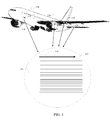
- FIG. 1 An exemplary embodiment of riblets having a structure as will be described in greater detail subsequently is shown as a portion of an aerodynamic surface for an aircraft is shown in FIG. 1 .
- the aircraft 110 employs a structure with a surface 111, shown enlarged, having multiple substantially parallel riblets 112 arranged parallel to the flow direction as represented by arrow 114.
- FIG. 2A shows a cross section of immediately adjacent riblets as may be applicable for high speed aerodynamic applications.
- the riblets may be spaced laterally on the surface 111.
- dimension 116 perpendicular to the surface 111 as shown in FIGs.
- riblets 112 shown in FIGs. 2A and 2B are integral to a complete paint layer 208.
- riblets may be formed from paint strips or stripes 210 separately applied to the aerodynamic surface 111 as shown in FIG. 2B and 4A . Spacing of the riblets may vary depending on the fluid dynamic properties of the air, water or other fluid for which the application of riblets is employed.
- the aerodynamic surface is typically curved and may be, without limitation, a portion of a wing, an engine nacelle, a control surface, a fuselage or other suitable surface. Therefore flexibility and conformability of the riblets on the surface may be required.
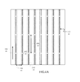
- the riblets may be discontinuous as shown in FIG. 4A with gaps 402 spaced at longitudinal distances 406 along the length of riblets 112. Separation 404 between paint strips forming riblets in the embodiment of FIG. 2B may be employed to eliminate lateral bending stresses which might deform riblets in the array.
- the embodiments disclosed herein are equally applicable for drag reduction on surfaces of other aerospace vehicles such as, without limitation, missiles or rockets and other vehicles such as cars, trucks, buses and trains moving in a gaseous fluid, commonly air, or on boats, submarines, hydrofoils, fluid flow conduits or other surfaces exposed to liquid fluid flow. While shown in the drawings previously described as substantially parallel, the riblets may be employed in an array of any coordinated pattern and may diverge, converge or intersect as shown in FIG. 4B .
- riblets may be created by an impression mold element in a malleable paint layer which has not yet dried.
- Computer controlled rollers encompassing the impression mold element can be passed over the airplane surfaces during painting of the airplane while the paint is still malleable, thereby mechanically embedding the desired topology into the final surface film.
- a textured surface encompassing the impression mold element is pressed against the paint while the paint is still malleable.
- riblets may be formed on or in a paint surface.
- computer controlled lasers are used to cut the required topology into the paint.
- lasers are used to pass over surfaces that are wetted with a paint or other agent activated by laser light or other catalyzing system for stereo lithographic building of riblet structure. The non-activated material can then be flushed away leaving the consolidated riblet structure in place.
- a print head 502 having an array of print jets 504 is supported by a controllable gantry 506.
- the array of print jets may be two dimensional to allow printing of multiple layers 508, 510 of paint along an axis of movement created by the gantry as well as painting a swath lateral to the axis of motion.
- the print heads 504 are shown in exaggerated size for clarity in the drawings but would be suitably sized for very small scale printing to allow sequential accumulation of multiple print "dots" to create the desired riblet size and shape.
- a computer control system 512 controls the gantry 506 for motion of the print head and also controls the array of print jets 504 to print the desired riblet profile and length.
- the two dimensional array of print jets 504 allows simultaneous printing of parallel riblets 112 and may also allow simultaneous printing of paint intermediate the riblets for a complete paint layer.
- riblets may be created in a malleable paint layer.
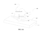
- an aerodynamic surface 111 with an applied layer of paint 602 which has not yet hardened and remains in a malleable condition is engaged by a roller 604 suspended from a controlled motion gantry 606.
- Roller 604 has a molded surface 605 having a negative impression of the desired riblet shape as will be described in greater detail subsequently.
- the riblet sizing on the roller is exaggerated in the figure for clarity.
- the gantry 606 is operated for motion along the aerodynamic surface 111 by a computer control system 608 which controls vertical motion of the gantry as well as lateral motion to roll the roller 604 over the paint layer.
- a sensor 610 on the gantry or roller provides force feedback to the computer control system 608 to allow appropriate pressure to be exerted by the gantry 606 through the roller 604 to form the riblets 112 in the malleable paint layer. Additional sensors for positioning and control of the roller on the aerodynamic surface by the computer control system 608 as well as input to the computer control system from a three dimensional CAD model may be employed as is known in the art.
- operation of the embodiment of FIG. 6A involves applying a paint layer to an aerodynamic surface, step 650.
- a roller having a negative profile mold of a riblet array is positioned with a mobile gantry under control of a computer control system above the aerodynamic surface prior to drying of the paint layer, step 652.
- the roller is then lowered into contact with the paint layer with sufficient pressure to imprint a riblet array in the paint layer, step 654, and rolled over the paint layer by the mobile gantry on a predetermined path to create the riblet array, step 656.
- Pressure on the roller is measured by a sensor for vertical control of the mobile gantry, step 658. Based on input from the sensor, the computer control system operates the mobile gantry to maintain a predetermined pressure on the roller, step 660.
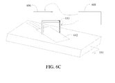
- a pressure foot 612 with a negative mold or imprint of the desired riblet profile may be attached to the gantry 606 as shown in FIG. 6C .
- the gantry 606 would then be sequentially positioned by the computer control system 608 and vertically pressed into the paint layer 602 to create the riblets and employing pressure sensor 610 for control feedback.
- Pressure foot 612 may be flexible to match the contour of the surface at the location positioned by the gantry.
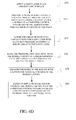
- a paint layer is applied to an aerodynamic surface, step 670.
- a pressure foot having a negative profile mold of a riblet array is positioned with a mobile gantry under control of a computer control system above the aerodynamic surface prior to drying of the paint layer, step 672.
- the pressure foot is then lowered into contact with the paint layer with sufficient pressure to imprint a riblet array in the paint layer, step 674.
- the pressure foot is then raised and moved by the mobile gantry to sequential positions on a predetermined path and lowered at each position to create the riblet array, step 676.
- Pressure on the pressure foot is measured by a sensor for vertical control of the mobile gantry, step 678. Based on input from the sensor, the computer control system operates the mobile gantry to create a predetermined pressure on the roller at each sequential position, step 680.
- FIG. 7A shows a master tool 712 which provides the necessary shape or profile 714 for the riblets.
- a moldable material is then applied to the master tool to create a negative mold 716 which may then be used to actually form the riblets in the malleable paint layer.
- master tool 712 may be created using, as an example, diamond machining of a copper form 718.
- An acrylate film 720, or similar material, is cured on the master tool 712, as shown in FIG. 7C .
- the film 720 may then be stripped from the master tool 712 and applied to a roller core722 to create the roller 604 as shown in FIG. 6A or applied to a pressure foot 612 as shown in FIG. 6C .
- FIG. 8 An integrated system may be employed as shown in FIG. 8 wherein a gantry 606 under control of a computer control system 608 as previously described, carries a paint application unit 802 which applies a paint layer under control of the computer control system 608.
- a roller 604 mounted on the gantry trailing the paint application unit 802 imprints the riblet profile into the paint layer as previously described with respect to FIG. 6A and 6B .
- the paint may employ a hardening or activating agent formulation and an activator 804 is mounted to the gantry 606 following the roller 604 to harden the formed paint layer including the riblets. UV or laser activation may be employed or, alternatively, a chemical hardener may be dispensed by the activator 804.
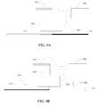
- a computer controlled laser 902 mounted to the gantry 606 is transitioned over the aerodynamic surface 111 with a paint layer 904 previously applied to the surface.
- the laser 902 is activated by the computer control system 608 to cut the required topology for the riblets into the paint layer 904.
- laser 902 under control computer control system 608 is passed by gantry 606 over the aerodynamic surface that has been wetted with an agent 906 by an applicator 908, wherein the agent is activated by laser light for stero lithographic building of structure for the riblets 112.
- the non-activated material is then flushed away by a spray nozzle 910 leaving the riblets 112 in place on the surface.
- the applicator 908 and spray nozzle 910 may be attached to the gantry 606 to lead and follow the laser 902 similar to the integrated system as described with respect to FIG. 8 .
- An alternative activating or other catalyzing system such as UV may be employed instead of the laser.
- the embodiments described herein allow rapid repair of damaged riblets by stripping of the paint layer in the damaged area and reapplication of paint and forming of riblets by any of the methods described.
- exemplary method 1000 may include specification and design 1004 of the aircraft, which may include the riblets, and material procurement 1006.
- component and subassembly manufacturing 1008 and system integration 1010 of the aircraft takes place.
- the rib let manufacturing processes as described herein may be accomplished as a portion of the production, component and subassembly manufacturing step 1008 and/or as a portion of the system integration 1010.
- the aircraft may go through certification and delivery 1012 in order to be placed in service 1014.
- routine maintenance and service 1016 (which may also include modification, reconfiguration, refurbishment, and so on).
- routine maintenance and service 1016 (which may also include modification, reconfiguration, refurbishment, and so on).
- the riblets embodied in paint as described herein may also be fabricated and applied as a portion of routine maintenance and service.
- a system integrator may include without limitation any number of aircraft manufacturers and major-system subcontractors; a third party may include without limitation any number of venders, subcontractors, and suppliers; and an operator may be an airline, leasing company, military entity, service organization, and so on.
- the aircraft 1102 produced by exemplary method 1000 may include an airframe 1118 having a surface 111, as described with respect to FIG. 1 , and a plurality of systems 1120 and an interior 1122.
- high-level systems 1120 include one or more of a propulsion systems 1124, an electrical and avionics system 1126, a hydraulic system 1128, and an environmental system 1130. Any number of other systems may be included.
- the paint riblets supported by the embodiments disclosed herein may be a portion of the airframe, notably the finishing of skin and exterior surfaces.
- an aerospace example is shown, the principles disclosed by the embodiments herein may be applied to other industries, such as the automotive industry and the marine/ship industry.
- Apparatus and methods embodied herein may be employed during any one or more of the stages of the production and service method 1000.
- components or subassemblies corresponding to production process 1008 may be fabricated or manufactured in a manner similar to components or subassemblies produced while the aircraft 1102 is in service.
- one or more apparatus embodiments, method embodiments, or a combination thereof may be utilized during the production stages 1008 and 1010, for example, by substantially expediting assembly of or reducing the cost of an aircraft 1102.
- one or more of apparatus embodiments, method embodiments, or a combination thereof may be utilized while the aircraft 1102 is in service, for example and without limitation, to maintenance and service 1016.
Landscapes
- Engineering & Computer Science (AREA)
- Mechanical Engineering (AREA)
- Physics & Mathematics (AREA)
- Manufacturing & Machinery (AREA)
- Chemical & Material Sciences (AREA)
- Materials Engineering (AREA)
- Fluid Mechanics (AREA)
- General Engineering & Computer Science (AREA)
- Aviation & Aerospace Engineering (AREA)
- Optics & Photonics (AREA)
- Plasma & Fusion (AREA)
- Application Of Or Painting With Fluid Materials (AREA)
Abstract
Description
- Embodiments of the disclosure relate generally to the field of surface geometries for aerodynamic improvements to aircraft or surfaces having a flow interface and more particularly to fabrication methods and apparatus for aerodynamic riblets formed in a paint layer.
- Increasing fuel efficiency in modem aircraft is being accomplished through improvement in aerodynamic performance and reduction of structural weight. Recent advances in the use of microstructures such as riblets on aerodynamic surfaces have shown significant promise in reducing drag to assist in reducing fuel usage. Riblets have various forms but advantageous embodiments may be ridge-like structures that minimize drag on the surface of an aircraft.
- In certain tested applications, riblets have been pyramidal or inverted V shaped ridges spaced on the aerodynamic surface to extend along the surface in the direction of fluid flow. Riblet structures have typically employed polymeric materials, typically thermoplastic in the form of appliques to create the desired topology. These appliques are bonded to the aircraft paint with adhesives. Polymers are relatively soft however, and may readily deform hundreds of percent with fingernail pressure and may be unrecoverable. Such structures may be undesirable in normal service use on an aircraft or other vehicle for they add weight and potentially dissolve when exposed to solvents. The strength of adhesives to bond the appliques to the vehicle surface may also create issues. Aircraft surfaces are typically required to withstand interactions with various chemicals including Skydrol®, a hydraulic fluid produced by Solutia, Inc.
- The practicality of riblets for commercial aircraft use would therefore be significantly enhanced with a riblet structure which is easily applied to aerodynamic surfaces, which does not add weight, is not easily compromised by exposure to the commercial air transport environment, and easily repaired or replaced when damaged.
- Exemplary embodiments provide a riblet forming system having a print head with an array of print jets. A gantry supports the print head and is positioned and moved over an aerodynamic surface. A computer control system is connected for control of the gantry on a predetermined path over the aerodynamic surface and further connected to the print head to control the print jets to sequentially apply print dots from the array of print jets forming a riblet profile along the predetermined path.
- In another embodiment, a riblet impression system incorporates an impression mold element and the gantry supports the impression mold element for positioning and motion over the aerodynamic surface. The computer control system is connected to and controls the gantry on a predetermined path over the aerodynamic surface and further controls the gantry vertically with respect to the aerodynamic surface to sequentially impress the impression mold element in a malleable paint layer on the aerodynamic surface forming a riblet profile along the predetermined path.
- In yet another embodiment, a riblet construction system employs a gantry adapted for motion over an aerodynamic surface on a predetermined path with a laser mounted to the gantry. A control system is connected to the gantry to move the gantry on the predetermined path and is connected to the laser to control the laser cutting a riblet topology in a predeposited paint layer.
- In a further embodiment, a riblet stereo lithography system includes an agent applicator applying a stereo lithographic agent on an aerodynamic surface. An activator trails the agent applicator on a predetermined path over the aerodynamic surface and activates the agent to create a riblet structure. A spray nozzle trails the activator and flushes away non-activated material leaving the riblet structure in place on the surface.
- An embodiment of the invention can involve a riblet forming system that may include a print head having an array of print jets; a gantry supporting the print head and adapted for positioning and motion over an aerodynamic surface; and, a computer control system connected for control of the gantry on a predetermined path over the aerodynamic surface and further connected to the print head controlling the print jets to sequentially apply print dots from the array of print jets forming a riblet profile along the predetermined path. The array of print jets may be two dimensional and said computer control system controls the print jets for application of parallel riblets. The computer control system may control the print jets for application of paint intermediate the riblets for a complete paint layer.
- An embodiment of the invention can involve a riblet impression system that may includean impression mold element; a gantry supporting the impression mold element and adapted for positioning and motion over an aerodynamic surface; and, a computer control system connected to and controlling the gantry on a predetermined path over the aerodynamic surface and further controlling the gantry vertically with respect to the aerodynamic surface to sequentially impress the impression mold element in a malleable paint layer on the aerodynamic surface forming a riblet profile along the predetermined path. The impression mold element may include a roller. The riblet impression mold element may include a pressure foot. The riblet impression system may also include a pressure sensor associated with the impression mold element and connected to the computer control system, said computer control system vertically controlling the gantry responsive to the pressure sensor. The riblet impression system may also include a paint application unit carried by the gantry, said impression mold element trailing the paint application unit and sequentially impressing the impression mold element in a malleable paint layer applied by the paint application unit on the aerodynamic surface. The riblet impression system may also include an activator mounted to the gantry following the roller, said activator hardening the formed paint layer including the riblets. The roller may further comprise an acrylate film cured on a master tool having a profile of the riblets said film stripped from the master tool and applied to a roller core. The pressure foot may also include an acrylate film cured on a master tool having a profile of the riblets said film stripped from the master tool and applied to the pressure foot.
- An embodiment of the invention can involve a riblet construction system that may include a gantry adapted for motion over an aerodynamic surface on a predetermined path; a laser mounted to the gantry; a control system connected to the gantry, said gantry moving on the predetermined path responsive to the control system, said control system further connected to the laser, said laser cutting a riblet topology in a predeposited paint layer responsive to the control system.
- An embodiment of the invention can involve a riblet stereo lithography system that may include an agent applicator applying a stero lithographic agent on an aerodynamic surface; an activator trailing the agent applicator on a predetermined path over the aerodynamic surface, said activator activating the agent to create a riblet structure; and, a spray nozzle trailing the activator and flushing away non-activated material leaving riblet structure in place on the surface. The riblet construction system as defined in claim 13 further comprising a gantry controllable over a predetermined path with respect to an aerodynamic surface, said agent applicator, activator and spray nozzle mounted to the gantry in trailing sequence. The activator may be a laser.
- An embodiment of the invention can involve a method for forming riblets on an aerodynamic surface that may include applying a paint layer to an aerodynamic surface; positioning an impression mold element having a negative profile mold of a riblet array prior to drying of the paint layer; lowering the impression mold element is into contact with the paint layer with sufficient pressure to imprint a riblet array in the paint layer; sequentially transitioning the impression mold element over the paint layer on a predetermined path to create a riblet array. The method may also include measuring pressure on the impression mold element to maintain a predetermined pressure. The positioning an impression mold element may include positioning a roller and sequentially transitioning comprises rolling the roller over the paint layer on a predetermined path to create a riblet array. The positioning an impression mold element may include positioning a pressure foot and sequentially transitioning may include raising and moving the pressure foot to sequential positions on a predetermined path and lowered at each position to create the riblet array. The method may also include machining a master tool with a riblet array profile; applying an acrylate film to the master tool creating a negative mold; stripping the acrylate film from the master tool; and, applying the acrylate film to an impression mold element.
- The embodiments provide a method for creation of riblets on an aerodynamic surface wherein a paint layer is applied to an aerodynamic surface. An impression mold element having a negative profile mold of a riblet array is positioned prior to drying of the paint layer and lowered into contact with the paint layer with sufficient pressure to imprint a riblet array in the paint layer. The impression mold element is sequentially transitioned over the paint layer on a predetermined path to create a riblet array.
- The features and advantages of embodiments disclosed herein will be better understood by reference to the following detailed description when considered in connection with the accompanying drawings wherein:
-
FIG. 1 is an isometric view of a portion of an aerodynamic surface such as a wing or fuselage skin showing exemplary riblets extending in the flow direction; -
FIG. 2A is a section view of an array of riblets in a paint layer as described for the embodiments herein; -
FIG. 2B is a section view of a generalized case wherein the riblets are separated by an extent of flat surface -
FIG 2B is a section view of an array of riblets created with paint on an aerodynamic surface as described for the embodiments herein; -
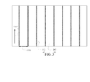
FIG. 3 is a top view of the array of riblets ofFIG. 2A ; -
FIG. 4A is a top view of the array of riblets ofFIG. 2B with additional features; -
FIG. 4B is a top view of an array of riblets with a predetermined coordinated pattern; -
FIG. 5 is a block diagram of a paint print head for application of riblets to an aerodynamic surface; -
FIG. 6A is a block diagram of an impression roller system for creating riblets in a malleable paint layer; -
FIG. 6B is a flow diagram of a method for creating riblets in a malleable paint layer with the impression roller system ofFIG. 6A ; -
FIG. 6C is a block diagram of an imprint block system for creating riblets in a malleable paint layer; -
FIG. 6D is a flow diagram of a method for creating riblets in a malleable paint layer with the imprint block system ofFIG. 6C ; -
FIG. 7A is a section schematic view of preparation of a master tool for creation of an impression roller or an imprint block for creating riblets in a malleable paint layer; -
FIG. 7B-7D provide a flow diagram of an alternative for preparation of a riblet negative for an impression roller or an imprint block for creating riblets in a malleable paint layer; -
FIG. 7E shows attachment of the riblet negative to a roller; -
FIG. 8 is a system block diagram for a multiple element system for dispensing paint, rolling the malleable paint with an impression roller and hardening the paint with a catalyzing agent; -
FIG. 9A is a block diagram of a laser system for cutting riblet topology into paint; -
FIG. 9B is a block diagram of a catalyzing system for stereo lithographic building of riblet structure; -
FIG. 10 is a flow diagram describing use of the riblet embodiments disclosed herein in the context of an aircraft manufacturing and service method; and -
FIG. 11 is a block diagram representing an aircraft employing the riblets with embodiments as disclosed herein. - An exemplary embodiment of riblets having a structure as will be described in greater detail subsequently is shown as a portion of an aerodynamic surface for an aircraft is shown in
FIG. 1 . Theaircraft 110 employs a structure with asurface 111, shown enlarged, having multiple substantiallyparallel riblets 112 arranged parallel to the flow direction as represented byarrow 114.FIG. 2A shows a cross section of immediately adjacent riblets as may be applicable for high speed aerodynamic applications. In a generalized case, as shown inFIG. 2B , the riblets may be spaced laterally on thesurface 111. For the exemplary embodiment shown, dimension 116 perpendicular to thesurface 111 as shown inFIGs. 2A and 2B and tip-to-tip spacing 118 between the riblets as shown inFIG. 3 are determined by the dynamic pressure, Q, exerted on the surface and may vary from location to location on the vehicle. Larger dimensions for the riblets and/or spacing may be present for hydrodynamic or low speed aerodynamic applications while extremely small dimension may be employed for high speed aerodynamic applications. Theriblets 112 shown inFIGs. 2A and 2B are integral to acomplete paint layer 208. Alternatively, riblets may be formed from paint strips orstripes 210 separately applied to theaerodynamic surface 111 as shown inFIG. 2B and4A . Spacing of the riblets may vary depending on the fluid dynamic properties of the air, water or other fluid for which the application of riblets is employed. The aerodynamic surface is typically curved and may be, without limitation, a portion of a wing, an engine nacelle, a control surface, a fuselage or other suitable surface. Therefore flexibility and conformability of the riblets on the surface may be required. To assist in providing necessary flexibility of the riblet structure, the riblets may be discontinuous as shown inFIG. 4A withgaps 402 spaced atlongitudinal distances 406 along the length ofriblets 112. Separation 404 between paint strips forming riblets in the embodiment ofFIG. 2B may be employed to eliminate lateral bending stresses which might deform riblets in the array. While described herein with respect to an aircraft aerodynamic surface the embodiments disclosed herein are equally applicable for drag reduction on surfaces of other aerospace vehicles such as, without limitation, missiles or rockets and other vehicles such as cars, trucks, buses and trains moving in a gaseous fluid, commonly air, or on boats, submarines, hydrofoils, fluid flow conduits or other surfaces exposed to liquid fluid flow. While shown in the drawings previously described as substantially parallel, the riblets may be employed in an array of any coordinated pattern and may diverge, converge or intersect as shown inFIG. 4B . - The embodiments disclosed herein provide multiple structures and apparatus for creating or applying riblets to a surface such as printing heads, which are computer controlled, and can be programmed to apply aircraft markings with high levels of accuracy. Such heads are employed to apply topcoat or clearcoat riblets. In other embodiments riblets may be created by an impression mold element in a malleable paint layer which has not yet dried. Computer controlled rollers encompassing the impression mold element can be passed over the airplane surfaces during painting of the airplane while the paint is still malleable, thereby mechanically embedding the desired topology into the final surface film. Alternatively, a textured surface encompassing the impression mold element is pressed against the paint while the paint is still malleable. Such a surface could be made of flexible material to eliminate a requirement for contour matching if a rigid material were used. In other embodiments, riblets may be formed on or in a paint surface. In one example, computer controlled lasers are used to cut the required topology into the paint. In another embodiment, lasers are used to pass over surfaces that are wetted with a paint or other agent activated by laser light or other catalyzing system for stereo lithographic building of riblet structure. The non-activated material can then be flushed away leaving the consolidated riblet structure in place.
- As shown in
FIG. 5 , aprint head 502 having an array ofprint jets 504 is supported by acontrollable gantry 506. The array of print jets may be two dimensional to allow printing ofmultiple layers computer control system 512 controls thegantry 506 for motion of the print head and also controls the array ofprint jets 504 to print the desired riblet profile and length. The two dimensional array ofprint jets 504 allows simultaneous printing ofparallel riblets 112 and may also allow simultaneous printing of paint intermediate the riblets for a complete paint layer. - An alternative to creating paint buildup to produce the riblet shape, riblets may be created in a malleable paint layer. As shown in
FIG. 6A , anaerodynamic surface 111 with an applied layer ofpaint 602 which has not yet hardened and remains in a malleable condition is engaged by aroller 604 suspended from a controlledmotion gantry 606.Roller 604 has a moldedsurface 605 having a negative impression of the desired riblet shape as will be described in greater detail subsequently. The riblet sizing on the roller is exaggerated in the figure for clarity. Thegantry 606 is operated for motion along theaerodynamic surface 111 by acomputer control system 608 which controls vertical motion of the gantry as well as lateral motion to roll theroller 604 over the paint layer. Asensor 610 on the gantry or roller provides force feedback to thecomputer control system 608 to allow appropriate pressure to be exerted by thegantry 606 through theroller 604 to form theriblets 112 in the malleable paint layer. Additional sensors for positioning and control of the roller on the aerodynamic surface by thecomputer control system 608 as well as input to the computer control system from a three dimensional CAD model may be employed as is known in the art. - As shown in
FIG. 6B , operation of the embodiment ofFIG. 6A involves applying a paint layer to an aerodynamic surface,step 650. A roller having a negative profile mold of a riblet array is positioned with a mobile gantry under control of a computer control system above the aerodynamic surface prior to drying of the paint layer,step 652. The roller is then lowered into contact with the paint layer with sufficient pressure to imprint a riblet array in the paint layer,step 654, and rolled over the paint layer by the mobile gantry on a predetermined path to create the riblet array,step 656. Pressure on the roller is measured by a sensor for vertical control of the mobile gantry,step 658. Based on input from the sensor, the computer control system operates the mobile gantry to maintain a predetermined pressure on the roller,step 660. - As an alternative to a roller, a
pressure foot 612 with a negative mold or imprint of the desired riblet profile may be attached to thegantry 606 as shown inFIG. 6C . Thegantry 606 would then be sequentially positioned by thecomputer control system 608 and vertically pressed into thepaint layer 602 to create the riblets and employingpressure sensor 610 for control feedback.Pressure foot 612 may be flexible to match the contour of the surface at the location positioned by the gantry. - Operation of the pressure foot is similar to the operation of the roller embodiment previously described. As shown in
FIG. 6D , a paint layer is applied to an aerodynamic surface,step 670. A pressure foot having a negative profile mold of a riblet array is positioned with a mobile gantry under control of a computer control system above the aerodynamic surface prior to drying of the paint layer,step 672. The pressure foot is then lowered into contact with the paint layer with sufficient pressure to imprint a riblet array in the paint layer,step 674. The pressure foot is then raised and moved by the mobile gantry to sequential positions on a predetermined path and lowered at each position to create the riblet array,step 676. Pressure on the pressure foot is measured by a sensor for vertical control of the mobile gantry,step 678. Based on input from the sensor, the computer control system operates the mobile gantry to create a predetermined pressure on the roller at each sequential position,step 680. - Shown in
FIGs. 7A-7E , is an exemplary tool fabrication technique for implementing the embodiments described with respect toFIGs. 6A and6C .FIG. 7A shows amaster tool 712 which provides the necessary shape orprofile 714 for the riblets. A moldable material is then applied to the master tool to create anegative mold 716 which may then be used to actually form the riblets in the malleable paint layer. As shown inFIG. 7B ,master tool 712 may be created using, as an example, diamond machining of acopper form 718. Anacrylate film 720, or similar material, is cured on themaster tool 712, as shown inFIG. 7C . As shown inFIG. 7D , thefilm 720 may then be stripped from themaster tool 712 and applied to a roller core722 to create theroller 604 as shown inFIG. 6A or applied to apressure foot 612 as shown inFIG. 6C . - An integrated system may be employed as shown in
FIG. 8 wherein agantry 606 under control of acomputer control system 608 as previously described, carries apaint application unit 802 which applies a paint layer under control of thecomputer control system 608. Aroller 604 mounted on the gantry trailing thepaint application unit 802 imprints the riblet profile into the paint layer as previously described with respect toFIG. 6A and6B . The paint may employ a hardening or activating agent formulation and anactivator 804 is mounted to thegantry 606 following theroller 604 to harden the formed paint layer including the riblets. UV or laser activation may be employed or, alternatively, a chemical hardener may be dispensed by theactivator 804. - In an embodiment shown in
FIG. 9A , a computer controlledlaser 902 mounted to thegantry 606 is transitioned over theaerodynamic surface 111 with apaint layer 904 previously applied to the surface. Thelaser 902 is activated by thecomputer control system 608 to cut the required topology for the riblets into thepaint layer 904. - In another embodiment shown in
FIG. 9B ,laser 902 under controlcomputer control system 608 is passed bygantry 606 over the aerodynamic surface that has been wetted with anagent 906 by anapplicator 908, wherein the agent is activated by laser light for stero lithographic building of structure for theriblets 112. The non-activated material is then flushed away by aspray nozzle 910 leaving theriblets 112 in place on the surface. Theapplicator 908 andspray nozzle 910 may be attached to thegantry 606 to lead and follow thelaser 902 similar to the integrated system as described with respect toFIG. 8 . An alternative activating or other catalyzing system such as UV may be employed instead of the laser. - The embodiments described herein allow rapid repair of damaged riblets by stripping of the paint layer in the damaged area and reapplication of paint and forming of riblets by any of the methods described.
- Referring more particularly to
FIGs. 10 and 11 , embodiments of the riblets disclosed herein and the methods for their fabrication may be described in the context of an aircraft manufacturing andservice method 1000 as shown inFIG. 10 and anaircraft 1102 as shown inFIG. 11 . During pre-production,exemplary method 1000 may include specification anddesign 1004 of the aircraft, which may include the riblets, andmaterial procurement 1006. During production, component andsubassembly manufacturing 1008 andsystem integration 1010 of the aircraft takes place. The rib let manufacturing processes as described herein may be accomplished as a portion of the production, component andsubassembly manufacturing step 1008 and/or as a portion of thesystem integration 1010. Thereafter, the aircraft may go through certification anddelivery 1012 in order to be placed in service 1014. While in service by a customer, the aircraft 1002 is scheduled for routine maintenance and service 1016 (which may also include modification, reconfiguration, refurbishment, and so on). The riblets embodied in paint as described herein may also be fabricated and applied as a portion of routine maintenance and service. - Each of the processes of
method 1000 may be performed or carried out by a system integrator, a third party, and/or an operator (e.g., a customer). For the purposes of this description, a system integrator may include without limitation any number of aircraft manufacturers and major-system subcontractors; a third party may include without limitation any number of venders, subcontractors, and suppliers; and an operator may be an airline, leasing company, military entity, service organization, and so on. - As shown in
FIG. 11 , theaircraft 1102 produced byexemplary method 1000 may include anairframe 1118 having asurface 111, as described with respect toFIG. 1 , and a plurality ofsystems 1120 and an interior 1122. Examples of high-level systems 1120 include one or more of apropulsion systems 1124, an electrical andavionics system 1126, ahydraulic system 1128, and anenvironmental system 1130. Any number of other systems may be included. The paint riblets supported by the embodiments disclosed herein may be a portion of the airframe, notably the finishing of skin and exterior surfaces. Although an aerospace example is shown, the principles disclosed by the embodiments herein may be applied to other industries, such as the automotive industry and the marine/ship industry. - Apparatus and methods embodied herein may be employed during any one or more of the stages of the production and
service method 1000. For example, components or subassemblies corresponding toproduction process 1008 may be fabricated or manufactured in a manner similar to components or subassemblies produced while theaircraft 1102 is in service. Also, one or more apparatus embodiments, method embodiments, or a combination thereof may be utilized during theproduction stages aircraft 1102. Similarly, one or more of apparatus embodiments, method embodiments, or a combination thereof may be utilized while theaircraft 1102 is in service, for example and without limitation, to maintenance andservice 1016. - Having now described various embodiments in detail as required by the patent statutes, those skilled in the art will recognize modifications and substitutions to the specific embodiments disclosed herein. Such modifications are within the scope and intent of the present disclosure as defined in the following claims.
Claims (13)
- A riblet impression system comprising:an impression mold element;a gantry supporting the impression mold element and adapted for positioning and motion over an aerodynamic surface; and,a computer control system connected to and controlling the gantry on a predetermined path over the aerodynamic surface and further controlling the gantry vertically with respect to the aerodynamic surface to sequentially impress the impression mold element in a malleable paint layer on the aerodynamic surface forming a riblet profile along the predetermined path.
- The riblet impression system as defined in claim 1 wherein the impression mold element comprises a roller.
- The riblet impression system as defined in claim 1 wherein the impression mold element comprises a pressure foot.
- The riblet impression system as defined in any of claims 1 to 3 further comprising a pressure sensor associated with the impression mold element and connected to the computer control system, said computer control system vertically controlling the gantry responsive to the pressure sensor.
- The riblet impression system as defined in any of claims 1 to 4 further comprising a paint application unit carried by the gantry, said impression mold element trailing the paint application unit and sequentially impressing the impression mold element in a malleable paint layer applied by the paint application unit on the aerodynamic surface.
- The riblet impression system as defined in claim 5 further comprising an activator mounted to the gantry following the roller, said activator hardening the formed paint layer including the riblets.
- The riblet impression system as defined in claim 2 wherein the roller further comprises an acrylate film cured on a master tool having a profile of the riblets said film stripped from the master tool and applied to a roller core.
- The riblet impression system as defined in claim 2 wherein the pressure foot further comprises an acrylate film cured on a master tool having a profile of the riblets said film stripped from the master tool and applied to the pressure foot.
- A method for forming riblets on an aerodynamic surface comprising:applying a paint layer to an aerodynamic surface;positioning an impression mold element having a negative profile mold of a riblet array prior to drying of the paint layer;lowering the impression mold element is into contact with the paint layer with sufficient pressure to imprint a riblet array in the paint layer;sequentially transitioning the impression mold element over the paint layer on a predetermined path to create a riblet array.
- The method as defined in claim 9 further comprising:measuring pressure on the impression mold element to maintain a predetermined pressure.
- The method as defined in claim 9 or 10 wherein positioning an impression mold element comprises positioning a roller and sequentially transitioning comprises rolling the roller over the paint layer on a predetermined path to create a riblet array.
- The method as defined in claim 9 or 10 wherein positioning an impression mold element comprises positioning a pressure foot and sequentially transitioning comprises raising and moving the pressure foot to sequential positions on a predetermined path and lowered at each position to create the riblet array.
- The method as defined in any of claims 9 to 12further comprising machining a master tool with a riblet array profile; applying an acrylate film to the master tool creating a negative mold; stripping the acrylate film from the master tool; and, applying the acrylate film to an impression mold element.
Priority Applications (1)
| Application Number | Priority Date | Filing Date | Title |
|---|---|---|---|
| EP17183847.7A EP3263447A1 (en) | 2014-08-01 | 2015-07-16 | Drag reduction riblets integrated in a paint layer |
Applications Claiming Priority (1)
| Application Number | Priority Date | Filing Date | Title |
|---|---|---|---|
| US14/450,089 US20160243586A1 (en) | 2014-08-01 | 2014-08-01 | Drag reduction riblets integrated in a paint layer |
Related Child Applications (1)
| Application Number | Title | Priority Date | Filing Date |
|---|---|---|---|
| EP17183847.7A Division EP3263447A1 (en) | 2014-08-01 | 2015-07-16 | Drag reduction riblets integrated in a paint layer |
Publications (1)
| Publication Number | Publication Date |
|---|---|
| EP2982599A1 true EP2982599A1 (en) | 2016-02-10 |
Family
ID=53785437
Family Applications (2)
| Application Number | Title | Priority Date | Filing Date |
|---|---|---|---|
| EP15177084.9A Withdrawn EP2982599A1 (en) | 2014-08-01 | 2015-07-16 | Drag reduction riblets integrated in a paint layer |
| EP17183847.7A Withdrawn EP3263447A1 (en) | 2014-08-01 | 2015-07-16 | Drag reduction riblets integrated in a paint layer |
Family Applications After (1)
| Application Number | Title | Priority Date | Filing Date |
|---|---|---|---|
| EP17183847.7A Withdrawn EP3263447A1 (en) | 2014-08-01 | 2015-07-16 | Drag reduction riblets integrated in a paint layer |
Country Status (4)
| Country | Link |
|---|---|
| US (2) | US20160243586A1 (en) |
| EP (2) | EP2982599A1 (en) |
| CN (1) | CN105398044A (en) |
| CA (1) | CA2890878A1 (en) |
Cited By (9)
| Publication number | Priority date | Publication date | Assignee | Title |
|---|---|---|---|---|
| DE102017218543A1 (en) | 2017-10-17 | 2019-04-18 | Lufthansa Technik Ag | Flow-optimized surface and vehicle with such a flow-optimized surface |
| FR3076540A1 (en) * | 2018-01-08 | 2019-07-12 | Airbus Operations | AERODYNAMIC ELEMENT OF AN AIRCRAFT COMPRISING A SET OF PROPERING ELEMENTS. |
| EP3782905A1 (en) * | 2019-08-21 | 2021-02-24 | Lockheed Martin Corporation | Partiallly submerged periodic riblets |
| EP3782904A1 (en) * | 2019-08-21 | 2021-02-24 | Lockheed Martin Corporation | Submerged periodic riblets |
| US11325208B2 (en) | 2018-12-21 | 2022-05-10 | Continental Teves Ag & Co. Ohg | Laser activation |
| FR3128150A1 (en) * | 2021-10-18 | 2023-04-21 | Safran Aircraft Engines | Process for printing riblets on the surface of a part and aeronautical part comprising riblets printed by such a process |
| EP4516518A1 (en) * | 2023-08-30 | 2025-03-05 | The Boeing Company | Methods for forming liquid management patterns on a surface of a structure of a vehicle |
| US12269574B2 (en) | 2020-02-11 | 2025-04-08 | The Boeing Company | Methods for forming liquid flow paths on a surface of a structure |
| US12275520B2 (en) | 2020-02-11 | 2025-04-15 | The Boeing Company | Liquid-diverting panel assemblies |
Families Citing this family (32)
| Publication number | Priority date | Publication date | Assignee | Title |
|---|---|---|---|---|
| EP3224024A1 (en) | 2014-11-24 | 2017-10-04 | PPG Industries Ohio, Inc. | Coreactive materials and methods for three-dimensional printing |
| US10059435B2 (en) * | 2014-12-04 | 2018-08-28 | Parker-Hannifin Corporation | Low drag skin heat exchanger |
| US9751618B2 (en) | 2015-05-06 | 2017-09-05 | The Boeing Company | Optical effects for aerodynamic microstructures |
| US9868135B2 (en) | 2015-05-06 | 2018-01-16 | The Boeing Company | Aerodynamic microstructures having sub-microstructures |
| US9714083B2 (en) | 2015-05-06 | 2017-07-25 | The Boeing Company | Color applications for aerodynamic microstructures |
| US10105877B2 (en) | 2016-07-08 | 2018-10-23 | The Boeing Company | Multilayer riblet applique and methods of producing the same |
| US20180244370A1 (en) * | 2017-02-18 | 2018-08-30 | Jean-Eloi William Lombard | Passive flow control mechanism for suppressing tollmien-schlichting waves, delaying transition to turbulence and reducing drag |
| DE102017206968B4 (en) * | 2017-04-26 | 2019-10-10 | 4Jet Microtech Gmbh & Co. Kg | Method and device for producing riblets |
| US12384097B2 (en) | 2017-08-18 | 2025-08-12 | Ppg Industries Ohio, Inc. | Additive manufacturing using reactive compositions |
| US10434704B2 (en) | 2017-08-18 | 2019-10-08 | Ppg Industries Ohio, Inc. | Additive manufacturing using polyurea materials |
| WO2019082309A1 (en) * | 2017-10-25 | 2019-05-02 | 株式会社ニコン | Processing device, coating, processing method, and method for producing moving body |
| US10760600B2 (en) | 2017-10-27 | 2020-09-01 | General Electric Company | Method of applying riblets to an aerodynamic surface |
| US11047239B2 (en) | 2018-12-03 | 2021-06-29 | General Electric Company | Method of forming a cure tool and method of forming a textured surface using a cure tool |
| JP7350080B2 (en) | 2019-02-11 | 2023-09-25 | ピーピージー・インダストリーズ・オハイオ・インコーポレイテッド | Multilayer systems and methods of manufacturing multilayer systems |
| KR102537828B1 (en) | 2019-02-11 | 2023-05-26 | 피피지 인더스트리즈 오하이오 인코포레이티드 | Methods of manufacturing chemical-resistant sealing components |
| WO2020167633A1 (en) | 2019-02-11 | 2020-08-20 | Ppg Industries Ohio, Inc. | 3d printing of seal caps |
| AU2020221556B2 (en) | 2019-02-11 | 2023-02-09 | Ppg Industries Ohio, Inc. | Elastomeric compositions and methods of use |
| EP3722007A1 (en) | 2019-03-29 | 2020-10-14 | Airbus Operations GmbH | Device for lacquer transfer |
| EP3750637A1 (en) | 2019-03-29 | 2020-12-16 | Airbus Operations GmbH | Device for a lacquer transfer |
| EP3722009A1 (en) | 2019-03-29 | 2020-10-14 | Airbus Operations GmbH | Device and system |
| EP3725539A1 (en) | 2019-03-29 | 2020-10-21 | Airbus Operations GmbH | Device for lacquer transfer |
| EP3733300A1 (en) | 2019-04-11 | 2020-11-04 | Airbus Operations GmbH | Device for a lacquer transfer |
| EP3725422B1 (en) | 2019-04-12 | 2025-01-29 | Airbus Operations GmbH | Device for lacquer transfer |
| US12649168B2 (en) * | 2020-02-11 | 2026-06-09 | The Boeing Company | Methods for forming liquid management patterns on a surface of a structure of a vehicle |
| DE102020007632A1 (en) * | 2020-12-14 | 2022-06-15 | Giesecke+Devrient Currency Technology Gmbh | Process for applying embossed structures to a surface of an object |
| CN112550679B (en) * | 2020-12-18 | 2023-04-07 | 上海机电工程研究所 | Micro-nano resistance reduction structure for high-altitude high-speed environment |
| US20220219195A1 (en) * | 2021-01-12 | 2022-07-14 | Airbus Operations Gmbh | Device for lacquer transfer |
| US11725524B2 (en) | 2021-03-26 | 2023-08-15 | General Electric Company | Engine airfoil metal edge |
| EP4374987A4 (en) * | 2021-06-22 | 2025-07-30 | Nikon Corp | Mold and blade member |
| US11987021B2 (en) | 2021-09-01 | 2024-05-21 | The Boeing Company | Multilayer riblet appliques |
| US11767607B1 (en) | 2022-07-13 | 2023-09-26 | General Electric Company | Method of depositing a metal layer on a component |
| US20250162702A1 (en) * | 2023-11-17 | 2025-05-22 | The Boeing Company | Method for Directly Applying Surface Texture for Improved Aerodynamics using Inkjet Printers |
Citations (5)
| Publication number | Priority date | Publication date | Assignee | Title |
|---|---|---|---|---|
| US20060068109A1 (en) * | 2004-09-15 | 2006-03-30 | Airbus Deutschland Gmbh | Painting device, painting arrangement, method for painting a curved surface of an object, and use of an inkjet device for painting an aircraft |
| DE102006004644A1 (en) * | 2006-01-31 | 2007-08-09 | Fraunhofer-Gesellschaft zur Förderung der angewandten Forschung e.V. | Layer fabricating tool for e.g. aircraft, has roller and die web arranged so that web arrives between roller and surface in rolling movement, during movement of roller, so that negative of microstructure on web faces substrate surface |
| US20100187359A1 (en) * | 2009-01-29 | 2010-07-29 | The Boeing Company | Rigid tipped riblets |
| US20110014429A1 (en) * | 2005-09-07 | 2011-01-20 | The Boeing Company | Composite Member Defining a Contour Surface |
| US20130062004A1 (en) * | 2007-12-12 | 2013-03-14 | The Boeing Company | Aerodynamic surfaces having drag-reducing riblets and method of fabricating the same |
Family Cites Families (14)
| Publication number | Priority date | Publication date | Assignee | Title |
|---|---|---|---|---|
| DE3534293A1 (en) * | 1985-09-26 | 1987-04-02 | Messerschmitt Boelkow Blohm | DEVICE FOR REDUCING FRICTION RESISTANCE |
| GB2226970B (en) * | 1989-01-11 | 1992-10-21 | British Aerospace | Methods of manufacture and surface treatment using laser radiation |
| GB2237656A (en) * | 1989-10-21 | 1991-05-08 | British Aerospace | Mask and method for the production of at least one groove, rib, or different intensity strip in or on a surface |
| US5194723A (en) * | 1991-12-24 | 1993-03-16 | Maxwell Laboratories, Inc. | Photoacoustic control of a pulsed light material removal process |
| US20080217813A1 (en) * | 1995-11-15 | 2008-09-11 | Chou Stephen Y | Release surfaces, particularly for use in nanoimprint lithography |
| US20080010924A1 (en) * | 2006-07-12 | 2008-01-17 | Pietruczynik Christopher B | Exterior building material having a hollow thin wall profile and an embossed low gloss surface |
| JP2002214414A (en) * | 2001-01-22 | 2002-07-31 | Omron Corp | Optical element provided with resin thin film having micro uneven pattern, method and apparatus for manufacturing optical element |
| US20030080472A1 (en) * | 2001-10-29 | 2003-05-01 | Chou Stephen Y. | Lithographic method with bonded release layer for molding small patterns |
| US6881370B2 (en) * | 2002-03-05 | 2005-04-19 | Karl R. Meyer | Method for fabricating a hard cover for an article |
| US8668166B2 (en) * | 2009-01-29 | 2014-03-11 | The Boeing Company | Shape memory riblets |
| US8678316B2 (en) * | 2009-01-29 | 2014-03-25 | The Boeing Company | Amorphous metal riblets |
| US8413928B2 (en) * | 2009-09-25 | 2013-04-09 | The Boeing Company | Structurally designed aerodynamic riblets |
| US9956720B2 (en) * | 2012-09-27 | 2018-05-01 | North Carolina State University | Methods and systems for fast imprinting of nanometer scale features in a workpiece |
| EP2839970B1 (en) * | 2013-08-21 | 2017-11-01 | Hueck Rheinische GmbH | Method for producing a hydrophobic or superhydrophobic surface topography |
-
2014
- 2014-08-01 US US14/450,089 patent/US20160243586A1/en not_active Abandoned
-
2015
- 2015-05-07 CA CA2890878A patent/CA2890878A1/en not_active Abandoned
- 2015-07-16 EP EP15177084.9A patent/EP2982599A1/en not_active Withdrawn
- 2015-07-16 EP EP17183847.7A patent/EP3263447A1/en not_active Withdrawn
- 2015-07-31 CN CN201510465307.3A patent/CN105398044A/en active Pending
-
2017
- 2017-06-08 US US15/617,380 patent/US20170266691A1/en not_active Abandoned
Patent Citations (5)
| Publication number | Priority date | Publication date | Assignee | Title |
|---|---|---|---|---|
| US20060068109A1 (en) * | 2004-09-15 | 2006-03-30 | Airbus Deutschland Gmbh | Painting device, painting arrangement, method for painting a curved surface of an object, and use of an inkjet device for painting an aircraft |
| US20110014429A1 (en) * | 2005-09-07 | 2011-01-20 | The Boeing Company | Composite Member Defining a Contour Surface |
| DE102006004644A1 (en) * | 2006-01-31 | 2007-08-09 | Fraunhofer-Gesellschaft zur Förderung der angewandten Forschung e.V. | Layer fabricating tool for e.g. aircraft, has roller and die web arranged so that web arrives between roller and surface in rolling movement, during movement of roller, so that negative of microstructure on web faces substrate surface |
| US20130062004A1 (en) * | 2007-12-12 | 2013-03-14 | The Boeing Company | Aerodynamic surfaces having drag-reducing riblets and method of fabricating the same |
| US20100187359A1 (en) * | 2009-01-29 | 2010-07-29 | The Boeing Company | Rigid tipped riblets |
Non-Patent Citations (1)
| Title |
|---|
| VOLKMAR STENZEL ET AL: "Drag-reducing paints for the reduction of fuel consumption in aviation and shipping", PROGRESS IN ORGANIC COATINGS, ELSEVIER BV, NL, vol. 70, no. 4, 2 September 2010 (2010-09-02), pages 224 - 229, XP028165501, ISSN: 0300-9440, [retrieved on 20101125], DOI: 10.1016/J.PORGCOAT.2010.09.026 * |
Cited By (12)
| Publication number | Priority date | Publication date | Assignee | Title |
|---|---|---|---|---|
| DE102017218543A1 (en) | 2017-10-17 | 2019-04-18 | Lufthansa Technik Ag | Flow-optimized surface and vehicle with such a flow-optimized surface |
| WO2019076539A1 (en) | 2017-10-17 | 2019-04-25 | Lufthansa Technik Ag | FLOW-optimized surface and vehicle with such a flow-optimized surface |
| FR3076540A1 (en) * | 2018-01-08 | 2019-07-12 | Airbus Operations | AERODYNAMIC ELEMENT OF AN AIRCRAFT COMPRISING A SET OF PROPERING ELEMENTS. |
| US11325208B2 (en) | 2018-12-21 | 2022-05-10 | Continental Teves Ag & Co. Ohg | Laser activation |
| EP3782905A1 (en) * | 2019-08-21 | 2021-02-24 | Lockheed Martin Corporation | Partiallly submerged periodic riblets |
| EP3782904A1 (en) * | 2019-08-21 | 2021-02-24 | Lockheed Martin Corporation | Submerged periodic riblets |
| US11614106B2 (en) | 2019-08-21 | 2023-03-28 | Lockheed Martin Corporation | Partially submerged periodic riblets |
| US12085102B2 (en) | 2019-08-21 | 2024-09-10 | Lockheed Martin Corporation | Submerged periodic riblets |
| US12269574B2 (en) | 2020-02-11 | 2025-04-08 | The Boeing Company | Methods for forming liquid flow paths on a surface of a structure |
| US12275520B2 (en) | 2020-02-11 | 2025-04-15 | The Boeing Company | Liquid-diverting panel assemblies |
| FR3128150A1 (en) * | 2021-10-18 | 2023-04-21 | Safran Aircraft Engines | Process for printing riblets on the surface of a part and aeronautical part comprising riblets printed by such a process |
| EP4516518A1 (en) * | 2023-08-30 | 2025-03-05 | The Boeing Company | Methods for forming liquid management patterns on a surface of a structure of a vehicle |
Also Published As
| Publication number | Publication date |
|---|---|
| CN105398044A (en) | 2016-03-16 |
| EP3263447A1 (en) | 2018-01-03 |
| CA2890878A1 (en) | 2016-02-01 |
| US20170266691A1 (en) | 2017-09-21 |
| US20160243586A1 (en) | 2016-08-25 |
Similar Documents
| Publication | Publication Date | Title |
|---|---|---|
| EP3263447A1 (en) | Drag reduction riblets integrated in a paint layer | |
| CN102481596B (en) | Method and device for smoothing surfaces of components, especially large structures | |
| EP3693270A1 (en) | Method of surface micro-texturing with a subtractive agent | |
| US9481451B2 (en) | Rigid tipped riblets | |
| US8088450B2 (en) | Automated wing painting system | |
| US9409206B2 (en) | Methods and systems for applying aerodynamically functional coatings to a surface | |
| CA2903476C (en) | Strippable film assembly and coating for drag reduction | |
| US10814351B2 (en) | High-viscosity sealant application system | |
| AU2019202566B2 (en) | Folded composite filler | |
| WO1989011343A2 (en) | Improvements in or relating to reduction of drag | |
| US20140262015A1 (en) | High Pressure Soft Lithography for Micro-Topographical Patterning of Molded Polymers and Composites | |
| Choi | Smart flow control with riblets | |
| DK2261117T3 (en) | Process for making a microstructured film | |
| US9855707B2 (en) | Method and system for forming masks | |
| CN111546621A (en) | Method for surface microtexturing with subtractive agents | |
| Aghanajafi et al. | Integration of three-dimensional printing technology for wind-tunnel model fabrication | |
| US9581763B2 (en) | Method for fabricating an optical device using a treated surface | |
| JP7816385B2 (en) | Master plate, libretto molding method, libretto transfer sheet and its manufacturing method, and tool | |
| US20250332763A1 (en) | Punch Forming a Composite Charge | |
| Bilinsky et al. | Growing Riblets with Light |
Legal Events
| Date | Code | Title | Description |
|---|---|---|---|
| PUAI | Public reference made under article 153(3) epc to a published international application that has entered the european phase |
Free format text: ORIGINAL CODE: 0009012 |
|
| AK | Designated contracting states |
Kind code of ref document: A1 Designated state(s): AL AT BE BG CH CY CZ DE DK EE ES FI FR GB GR HR HU IE IS IT LI LT LU LV MC MK MT NL NO PL PT RO RS SE SI SK SM TR |
|
| AX | Request for extension of the european patent |
Extension state: BA ME |
|
| TPAC | Observations filed by third parties |
Free format text: ORIGINAL CODE: EPIDOSNTIPA |
|
| 17P | Request for examination filed |
Effective date: 20160810 |
|
| RBV | Designated contracting states (corrected) |
Designated state(s): AL AT BE BG CH CY CZ DE DK EE ES FI FR GB GR HR HU IE IS IT LI LT LU LV MC MK MT NL NO PL PT RO RS SE SI SK SM TR |
|
| 17Q | First examination report despatched |
Effective date: 20170201 |
|
| STAA | Information on the status of an ep patent application or granted ep patent |
Free format text: STATUS: THE APPLICATION IS DEEMED TO BE WITHDRAWN |
|
| 18D | Application deemed to be withdrawn |
Effective date: 20170812 |