EP2982597A1 - Tail spar spring - Google Patents
Tail spar spring Download PDFInfo
- Publication number
- EP2982597A1 EP2982597A1 EP15177693.7A EP15177693A EP2982597A1 EP 2982597 A1 EP2982597 A1 EP 2982597A1 EP 15177693 A EP15177693 A EP 15177693A EP 2982597 A1 EP2982597 A1 EP 2982597A1
- Authority
- EP
- European Patent Office
- Prior art keywords
- empennage
- aft
- outer member
- coupled
- aircraft
- Prior art date
- Legal status (The legal status is an assumption and is not a legal conclusion. Google has not performed a legal analysis and makes no representation as to the accuracy of the status listed.)
- Granted
Links
Images




Classifications
-
- B—PERFORMING OPERATIONS; TRANSPORTING
- B64—AIRCRAFT; AVIATION; COSMONAUTICS
- B64C—AEROPLANES; HELICOPTERS
- B64C5/00—Stabilising surfaces
- B64C5/02—Tailplanes
-
- B—PERFORMING OPERATIONS; TRANSPORTING
- B64—AIRCRAFT; AVIATION; COSMONAUTICS
- B64C—AEROPLANES; HELICOPTERS
- B64C1/00—Fuselages; Constructional features common to fuselages, wings, stabilising surfaces or the like
- B64C1/26—Attaching the wing or tail units or stabilising surfaces
-
- B—PERFORMING OPERATIONS; TRANSPORTING
- B64—AIRCRAFT; AVIATION; COSMONAUTICS
- B64C—AEROPLANES; HELICOPTERS
- B64C5/00—Stabilising surfaces
- B64C5/10—Stabilising surfaces adjustable
-
- B—PERFORMING OPERATIONS; TRANSPORTING
- B64—AIRCRAFT; AVIATION; COSMONAUTICS
- B64C—AEROPLANES; HELICOPTERS
- B64C29/00—Aircraft capable of landing or taking-off vertically, e.g. vertical take-off and landing [VTOL] aircraft
- B64C29/0008—Aircraft capable of landing or taking-off vertically, e.g. vertical take-off and landing [VTOL] aircraft having its flight directional axis horizontal when grounded
- B64C29/0016—Aircraft capable of landing or taking-off vertically, e.g. vertical take-off and landing [VTOL] aircraft having its flight directional axis horizontal when grounded the lift during taking-off being created by free or ducted propellers or by blowers
- B64C29/0033—Aircraft capable of landing or taking-off vertically, e.g. vertical take-off and landing [VTOL] aircraft having its flight directional axis horizontal when grounded the lift during taking-off being created by free or ducted propellers or by blowers the propellers being tiltable relative to the fuselage
Definitions
- This invention relates generally to aircraft tails, and more particularly, to a tail spar spring.
- a rotorcraft may include one or more rotor systems.
- a rotorcraft rotor system is a main rotor system.
- a main rotor system may generate aerodynamic lift to support the weight of the rotorcraft in flight and thrust to counteract aerodynamic drag and move the rotorcraft in forward flight.
- Another example of a rotorcraft rotor system is a tail rotor system.
- a tail rotor system may generate thrust in the same direction as the main rotor system's rotation to counter the torque effect created by the main rotor system.
- a technical advantage of one embodiment may include the capability to achieve global reduction in oscillatory loads and vibration in an aircraft. Teachings of certain embodiments recognize the ability to react to critical tail fin loads while allowing for axial motion to tailor aircraft dynamic tuning.
- FIGURE 1 shows a rotorcraft 100 according to one example embodiment.
- Rotorcraft 100 features rotor systems 110a and 110b, blades 120, a fuselage 130, a landing gear 140, a wing 150, and an empennage 160.
- Rotor system 110 may rotate blades 120.
- Rotor system 110 may include a control system for selectively controlling the pitch of each blade 120 in order to selectively control direction, thrust, and lift of rotorcraft 100.
- rotorcraft 100 represents a tiltrotor aircraft, and rotor systems 110a and 110b feature rotatable nacelles.
- the position of nacelles 110a and 110b, as well as the pitch of rotor blades 120, can be selectively controlled in order to selectively control direction, thrust, and lift of tiltrotor aircraft 100.
- Fuselage 130 represents the main body of rotorcraft 100 and may be coupled to rotor system 110 (e.g., via wing 150) such that rotor system 110 and blades 120 may move fuselage 130 through the air.
- Landing gear 140 supports rotorcraft 100 when rotorcraft 100 is landing and/or when rotorcraft 100 is at rest on the ground.
- Teachings of certain embodiments relating to rotor systems described herein may apply to rotor system 110 and/or other rotor systems, such as non-tilting rotor and helicopter rotor systems. It should also be appreciated that teachings from rotorcraft 100 may apply to aircraft other than rotorcraft, such as airplanes and unmanned aircraft, to name a few examples.
- tiltrotor aircraft 100 may operate in a helicopter mode by tilting the nacelles upright and in an airplane mode by tilting the nacelles forward. Tiltrotor aircraft 100 may generate greater forward speed in airplane mode than in helicopter mode because, in airplane mode, blades 120 are oriented to generate greater thrust propelling the aircraft forward (somewhat analogous to a propeller).
- Rotorcraft 100 also features at least one empennage 160.
- Empennage 160 represents a flight control surface coupled to the tail portion of fuselage 130.
- rotorcraft 100 features two empennages 160.
- the combination of the two empennages 160 may represent a v-tail configuration.
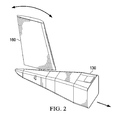
- FIGURE 2 shows a closer view of fuselage 130 and one empennage 160 of rotorcraft 100 according to one example embodiment.
- empennage 160 may be subject to a variety of forces, including a force against empennage 160 in the chordwise direction, as seen in the example of FIGURE 2 .
- Teachings of certain embodiments recognize the capability to reduce stiffness of empennage 160 in the chordwise direction while still maintaining the strength of empennage 160 in other directions. Teachings of certain embodiments also recognize the capability to achieve global reduction in oscillatory loads and vibration. Teachings of certain embodiments recognize the ability to react to critical tail fin loads while allowing for axial motion to tailor aircraft dynamic tuning.
- Some example embodiments may provide axial compliance to the vertical tail of a tiltrotor aircraft to tailor airframe dynamic tuning and thus achieve large global reductions in oscillatory loading and vibration.
- Some tiltrotor aircraft may be sensitive to the contributions of the tail vertical surfaces to the overall dynamic response of a tilt rotor aircraft. For example, stiffness of the tail joint may have a large impact on vibrations such as 3/rev vibrations. Accordingly, vibration modes may be improved by decoupling the tail vibration modes from the fuselage bending modes. Teachings of certain embodiments recognize that softening the tail joint connection may allow the airframe vibration mode to be moved away from the 3/rev position.
- Teachings of certain embodiments recognize the capability to improve airframe (and particular tail section) design as compared to tuning methods for dynamic tuning of fundamental aircraft loads, such as stiffening airframe structures or adjusting mass distribution. Such tuning methods may involve intrusive design medications, which may be prohibitive to NRE cost and schedule. Additionally, stiffening of airframe structures for dynamic tuning of fundamental airframe modes may result in tremendous weight impacts. Redistribution of masses to achieve meaningful dynamic tuning of fundamental fuselage modes may also not be feasible without the use of dedicated tuning masses, which also involves added parasitic weight.
- FIGURE 3 shows an internal plan view of empennage 160 according to one example embodiment.
- empennage 160 features an aft spar 162 and a forward spar 166.
- Aft spar 162 is attached to fuselage 130 via an aft attachment mechanism 164.
- Forward spar 166 is attached to fuselage 130 via a forward attachment system 200.
- Aft attachment mechanism 164 is coupled to fuselage 130 and to empennage 160 proximate to aft spar 162.
- aft attachment mechanism 164 defines a pitch axis 165 such that aft attachment mechanism 164 allows empennage 160 to rotate about pitch axis 165.
- aft attachment mechanism 164 comprises an elongated pin defining the pitch axis and a receiver portion coupled at least partially about the elongated pin and configured to rotate about the elongated pin.
- pitch axis 165 extends into and out of the page and is oriented perpendicular to the plan view of empennage 160.
- aft attachment mechanism 164 may allow empennage 160 to rotate forward and aft in response to the forces in the chordwise direction discussed above with regard to FIGURE 2 .
- Forward attachment system 200 is coupled to fuselage 130 and to empennage 160 proximate to forward spar 166. As will be explained in greater detail below, forward attachment system 200 is configured to restrict rotation of empennage 160 about pitch axis 165 to an allowable range of motion.
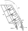
- FIGURE 4 shows movement of empennage 160 in the forward/aft direction according to one example embodiment.
- empennage 160 has rotated forward about pitch axis 165 to a new empennage position 160'.
- rotating empennage 160 about pitch axis 165 changes the distance between forward spar 166 and fuselage 130.
- teachings of certain embodiments recognize the capability to restrict rotation of empennage 160 about pitch axis 165 to an allowable range of motion and to provide structural support to empennage 160.
- FIGURE 5 shows a perspective view of forward attachment system 200 installed on empennage 160
- FIGURE 6 shows a side view of forward attachment system 200 installed between forward spar 166 and fuselage 130 according to one example embodiment.
- forward attachment system 200 provides axial softness in the span direction and beamwise stiffness in rotation about the chord direction. As will be explained in greater detail below, however, this axial softness in the span direction is not without limitation; rather, forward attachment system 200 may restrict some movement in the span direction so as to restrict rotation of empennage 160 about pitch axis 165 to an allowable range of motion.
- FIGURES 7A-7D show forward attachment system 200 according to one example embodiment.
- FIGURE 7A shows a side view of forward attachment system 200 attached between forward spar 166 and fuselage 130.
- forward attachment system 200 features an inner member 210, an outer member 220, and pads 230.
- Inner member 210 is configured to slide within outer member 220, and pads 230 restrict movement of inner member 210 relative to outer member 220.
- inner member 210 is coupled to forward spar 166
- outer member 220 is coupled to fuselage 130; in other embodiments, however, outer member 220 may be coupled to forward spar 166, and inner member 210 may be coupled to fuselage 130.
- FIGURE 7B shows a cross-section of forward attachment system 200 featuring two of pads 230 secured between inner member 210 and outer member 220.
- pads 230 may be secured between inner member 210 and outer member 220 in a variety of manners.
- pads 230 are bonded to both inner member 210 and outer member 220.
- bonding pads 230 to both inner member 210 and outer member 220 may prevent over-rotation of empennage 160 by restricting rotation of empennage 160 about pitch axis 165 to an allowable range of motion.
- pads 230 may also restrict movement of inner member 210 relative to outer member 220 in other directions, such as preventing inner member 210 from directly contacting outer member 220.
- Pads 230 may be made of any variety of materials, such as elastomer materials, silicone, composite, metal flexure, or any other suitable material.
- Elastomeric material may include any material, such as a polymer, that has the property of viscoelasticity (colloquially, "elasticity").
- An example of an elastomeric material is rubber.
- Elastomeric materials generally have a low Young's modulus and a high yield strain when compared to other materials.
- Elastomeric materials are typically thermosets having long polymer chains that cross-link during curing (i.e., vulcanizing). Elastomeric materials may absorb energy during compression but may also be prone failure during tension and torsion.
- inner member 210 appears to be coaxially aligned inside outer member 220 in FIGURES 7A and 7B , teachings of certain embodiments recognize that inner member 210 may not move perfectly along a line coaxial with void within outer member 220.
- inner member 210 should actually travel along a circumferential path relative to pitch axis 165. Principles of geometry require that this circumferential path be curved. Accordingly, inner member 210 moves along a curved path within outer member 220, not along a straight line within outer member 220.
- forward attachment system 200 may be configured such that inner member 210 and outer member 220 move substantially axially relative to each other. Although inner member 210 may move on a circumferential path, it may behave as if it travels in an axial path. Such a configuration may be accomplished, for example, by locating and orienting pads 230 so as to minimize any additional stiffening due to motion in a circumferential path and by selecting axial stiffness to limit chordwise rotation (e.g., limiting chordwise rotation to more than 0.25 degrees).
- hard stops may be provided to restrict inner member 210 from moving too far relative to outer member 220, or stated another way, to restrict movement of these components to a certain range of motion.
- restricting movement of inner member 210 relative to outer member 220 may also lengthen the operating lives of pads 230.
- pads 230 may be made of an elastomeric material, and many elastomeric materials perform well in compression but poorly in tension and/or shear. Accordingly, when one pad 230 compresses to restrict further rotation of empennage 160, this action also prevents over-tension or over-shear of the other pads 230.
- FIGURE 7C shows front attachment system 200 removed from forward spar 166 and fuselage 130
- FIGURE 7D shows a cross-section view of front attachment system 200
- inner member 210 features bosses 212
- outer member 220 features bosses 222.
- teachings of certain embodiments recognize that features such as bosses 212 and 222 may allow force to be transferred between inner member 210 and forward spar 166 and between outer member 222 and fuselage 130.
- the four bosses are substantially cylindrical, but other embodiments may feature bosses of other shapes, sizes, or quantities.
Landscapes
- Engineering & Computer Science (AREA)
- Aviation & Aerospace Engineering (AREA)
- Mechanical Engineering (AREA)
- Tires In General (AREA)
Abstract
Description
- Pursuant to 35 U.S.C. § 119 (e), this application claims priority to United States Provisional Patent Application Serial No.
62/034,211 62/034,211 - At least some of the subject matter of this application may have been made with government support under W911 W6-13-2-0001 awarded by the United States Army under the Future Vertical Lift program. The government may have certain rights in the invention.
- This invention relates generally to aircraft tails, and more particularly, to a tail spar spring.
- A rotorcraft may include one or more rotor systems. One example of a rotorcraft rotor system is a main rotor system. A main rotor system may generate aerodynamic lift to support the weight of the rotorcraft in flight and thrust to counteract aerodynamic drag and move the rotorcraft in forward flight. Another example of a rotorcraft rotor system is a tail rotor system. A tail rotor system may generate thrust in the same direction as the main rotor system's rotation to counter the torque effect created by the main rotor system.
- Particular embodiments of the present disclosure may provide one or more technical advantages. A technical advantage of one embodiment may include the capability to achieve global reduction in oscillatory loads and vibration in an aircraft. Teachings of certain embodiments recognize the ability to react to critical tail fin loads while allowing for axial motion to tailor aircraft dynamic tuning.
- Certain embodiments of the present disclosure may include some, all, or none of the above advantages. One or more other technical advantages may be readily apparent to those skilled in the art from the figures, descriptions, and claims included herein.
- To provide a more complete understanding of the present invention and the features and advantages thereof, reference is made to the following description taken in conjunction with the accompanying drawings, in which:
-
FIGURE 1 shows a tiltrotor aircraft according to one example embodiment; -
FIGURE 2 shows a closer view of the fuselage and one empennage of the tiltrotor aircraft ofFIGURE 1 ; -
FIGURE 3 shows an internal plan view of the empennage ofFIGURE 2 according to one example embodiment; -
FIGURE 4 shows movement of the empennage ofFIGURE 3 in the forward/aft direction according to one example embodiment; -
FIGURE 5 shows a perspective view of a forward attachment system installed on the empennage ofFIGURE 3 according to one example embodiment; -
FIGURE 6 shows a side view of the forward attachment system ofFIGURE 5 installed between the forward spar of the empennage and the fuselage ofFIGURE 3 according to one example embodiment; and -
FIGURES 7A-7D show various views of the forward attachment system of -
FIGURE 5 according to one example embodiment. -
FIGURE 1 shows arotorcraft 100 according to one example embodiment. Rotorcraft 100 featuresrotor systems blades 120, afuselage 130, alanding gear 140, awing 150, and anempennage 160. - Rotor system 110 may rotate
blades 120. Rotor system 110 may include a control system for selectively controlling the pitch of eachblade 120 in order to selectively control direction, thrust, and lift ofrotorcraft 100. In the example ofFIGURE 1A ,rotorcraft 100 represents a tiltrotor aircraft, androtor systems nacelles rotor blades 120, can be selectively controlled in order to selectively control direction, thrust, and lift oftiltrotor aircraft 100. -
Fuselage 130 represents the main body ofrotorcraft 100 and may be coupled to rotor system 110 (e.g., via wing 150) such that rotor system 110 andblades 120 may movefuselage 130 through the air.Landing gear 140 supportsrotorcraft 100 when rotorcraft 100 is landing and/or when rotorcraft 100 is at rest on the ground. - Teachings of certain embodiments relating to rotor systems described herein may apply to rotor system 110 and/or other rotor systems, such as non-tilting rotor and helicopter rotor systems. It should also be appreciated that teachings from
rotorcraft 100 may apply to aircraft other than rotorcraft, such as airplanes and unmanned aircraft, to name a few examples. - In the example of
FIGURE 1 ,tiltrotor aircraft 100 may operate in a helicopter mode by tilting the nacelles upright and in an airplane mode by tilting the nacelles forward.Tiltrotor aircraft 100 may generate greater forward speed in airplane mode than in helicopter mode because, in airplane mode,blades 120 are oriented to generate greater thrust propelling the aircraft forward (somewhat analogous to a propeller). - Rotorcraft 100 also features at least one
empennage 160.Empennage 160 represents a flight control surface coupled to the tail portion offuselage 130. In the example ofFIGURE 1 , rotorcraft 100 features twoempennages 160. In this example embodiment, the combination of the twoempennages 160 may represent a v-tail configuration. -
FIGURE 2 shows a closer view offuselage 130 and oneempennage 160 ofrotorcraft 100 according to one example embodiment. During operation ofrotorcraft 100,empennage 160 may be subject to a variety of forces, including a force againstempennage 160 in the chordwise direction, as seen in the example ofFIGURE 2 . - Teachings of certain embodiments recognize the capability to reduce stiffness of
empennage 160 in the chordwise direction while still maintaining the strength ofempennage 160 in other directions. Teachings of certain embodiments also recognize the capability to achieve global reduction in oscillatory loads and vibration. Teachings of certain embodiments recognize the ability to react to critical tail fin loads while allowing for axial motion to tailor aircraft dynamic tuning. - Some example embodiments may provide axial compliance to the vertical tail of a tiltrotor aircraft to tailor airframe dynamic tuning and thus achieve large global reductions in oscillatory loading and vibration. Some tiltrotor aircraft may be sensitive to the contributions of the tail vertical surfaces to the overall dynamic response of a tilt rotor aircraft. For example, stiffness of the tail joint may have a large impact on vibrations such as 3/rev vibrations. Accordingly, vibration modes may be improved by decoupling the tail vibration modes from the fuselage bending modes. Teachings of certain embodiments recognize that softening the tail joint connection may allow the airframe vibration mode to be moved away from the 3/rev position.
- Teachings of certain embodiments recognize the capability to improve airframe (and particular tail section) design as compared to tuning methods for dynamic tuning of fundamental aircraft loads, such as stiffening airframe structures or adjusting mass distribution. Such tuning methods may involve intrusive design medications, which may be prohibitive to NRE cost and schedule. Additionally, stiffening of airframe structures for dynamic tuning of fundamental airframe modes may result in tremendous weight impacts. Redistribution of masses to achieve meaningful dynamic tuning of fundamental fuselage modes may also not be feasible without the use of dedicated tuning masses, which also involves added parasitic weight.
-
FIGURE 3 shows an internal plan view ofempennage 160 according to one example embodiment. As seen in the example ofFIGURE 3 ,empennage 160 features anaft spar 162 and aforward spar 166. Aftspar 162 is attached tofuselage 130 via anaft attachment mechanism 164.Forward spar 166 is attached tofuselage 130 via aforward attachment system 200. -
Aft attachment mechanism 164 is coupled tofuselage 130 and to empennage 160 proximate toaft spar 162. In the example ofFIGURE 3 ,aft attachment mechanism 164 defines apitch axis 165 such thataft attachment mechanism 164 allowsempennage 160 to rotate aboutpitch axis 165. In one example embodiment,aft attachment mechanism 164 comprises an elongated pin defining the pitch axis and a receiver portion coupled at least partially about the elongated pin and configured to rotate about the elongated pin. - As seen in the example of
FIGURE 3 ,pitch axis 165 extends into and out of the page and is oriented perpendicular to the plan view ofempennage 160. Teachings of certain embodiments recognize thataft attachment mechanism 164 may allowempennage 160 to rotate forward and aft in response to the forces in the chordwise direction discussed above with regard toFIGURE 2 . -
Forward attachment system 200 is coupled tofuselage 130 and to empennage 160 proximate to forwardspar 166. As will be explained in greater detail below,forward attachment system 200 is configured to restrict rotation ofempennage 160 aboutpitch axis 165 to an allowable range of motion. -
FIGURE 4 shows movement ofempennage 160 in the forward/aft direction according to one example embodiment. In the example ofFIGURE 4 ,empennage 160 has rotated forward aboutpitch axis 165 to a new empennage position 160'. As seen in this example, however,rotating empennage 160 aboutpitch axis 165 changes the distance betweenforward spar 166 andfuselage 130. Accordingly, teachings of certain embodiments recognize the capability to restrict rotation ofempennage 160 aboutpitch axis 165 to an allowable range of motion and to provide structural support toempennage 160. -
FIGURE 5 shows a perspective view offorward attachment system 200 installed onempennage 160, andFIGURE 6 shows a side view offorward attachment system 200 installed betweenforward spar 166 andfuselage 130 according to one example embodiment. In the example ofFIGURES 5 and6 ,forward attachment system 200 provides axial softness in the span direction and beamwise stiffness in rotation about the chord direction. As will be explained in greater detail below, however, this axial softness in the span direction is not without limitation; rather,forward attachment system 200 may restrict some movement in the span direction so as to restrict rotation ofempennage 160 aboutpitch axis 165 to an allowable range of motion. -
FIGURES 7A-7D showforward attachment system 200 according to one example embodiment.FIGURE 7A shows a side view offorward attachment system 200 attached betweenforward spar 166 andfuselage 130. In this example embodiment,forward attachment system 200 features aninner member 210, anouter member 220, andpads 230.Inner member 210 is configured to slide withinouter member 220, andpads 230 restrict movement ofinner member 210 relative toouter member 220. In the example ofFIGURE 7A ,inner member 210 is coupled toforward spar 166, andouter member 220 is coupled tofuselage 130; in other embodiments, however,outer member 220 may be coupled toforward spar 166, andinner member 210 may be coupled tofuselage 130. -
FIGURE 7B shows a cross-section offorward attachment system 200 featuring two ofpads 230 secured betweeninner member 210 andouter member 220. In the example ofFIGURES 7A and 7B , four pads are provided-two on each side ofinner member 210.Pads 230 may be secured betweeninner member 210 andouter member 220 in a variety of manners. In one example embodiment,pads 230 are bonded to bothinner member 210 andouter member 220. Teachings of certain embodiments recognize thatbonding pads 230 to bothinner member 210 andouter member 220 may prevent over-rotation ofempennage 160 by restricting rotation ofempennage 160 aboutpitch axis 165 to an allowable range of motion. In this example embodiment,pads 230 may also restrict movement ofinner member 210 relative toouter member 220 in other directions, such as preventinginner member 210 from directly contactingouter member 220. -
Pads 230 may be made of any variety of materials, such as elastomer materials, silicone, composite, metal flexure, or any other suitable material. Elastomeric material may include any material, such as a polymer, that has the property of viscoelasticity (colloquially, "elasticity"). An example of an elastomeric material is rubber. Elastomeric materials generally have a low Young's modulus and a high yield strain when compared to other materials. Elastomeric materials are typically thermosets having long polymer chains that cross-link during curing (i.e., vulcanizing). Elastomeric materials may absorb energy during compression but may also be prone failure during tension and torsion. - Although
inner member 210 appears to be coaxially aligned insideouter member 220 inFIGURES 7A and 7B , teachings of certain embodiments recognize thatinner member 210 may not move perfectly along a line coaxial with void withinouter member 220. In particular, becauseempennage 160 rotates aboutpitch axis 165 defined byaft attachment mechanism 164 and becauseinner member 210 is located a distance away frompitch axis 165,inner member 210 should actually travel along a circumferential path relative to pitchaxis 165. Principles of geometry require that this circumferential path be curved. Accordingly,inner member 210 moves along a curved path withinouter member 220, not along a straight line withinouter member 220. - Teachings of certain embodiments recognize that, although
empennage 160 may rotate relative to pitchaxis 165,forward attachment system 200 may be configured such thatinner member 210 andouter member 220 move substantially axially relative to each other. Althoughinner member 210 may move on a circumferential path, it may behave as if it travels in an axial path. Such a configuration may be accomplished, for example, by locating and orientingpads 230 so as to minimize any additional stiffening due to motion in a circumferential path and by selecting axial stiffness to limit chordwise rotation (e.g., limiting chordwise rotation to more than 0.25 degrees). Teachings of certain embodiments recognizing that configuringinner member 210 to behave as if it travels in an axial path may preventforward attachment system 200 from being over-constrained, which would limit the amount of axial compliance available to tune the aircraft modes. Teachings of certain embodiments also recognize that configuringinner member 210 to behave as if it travels in an axial path may allow for improved aircraft tuning by altering only one stiffness direction (e.g., the axial motion direction). - In some embodiments, hard stops may be provided to restrict
inner member 210 from moving too far relative toouter member 220, or stated another way, to restrict movement of these components to a certain range of motion. Teachings of certain embodiments recognize that restricting movement ofinner member 210 relative toouter member 220 may also lengthen the operating lives ofpads 230. For example,pads 230 may be made of an elastomeric material, and many elastomeric materials perform well in compression but poorly in tension and/or shear. Accordingly, when onepad 230 compresses to restrict further rotation ofempennage 160, this action also prevents over-tension or over-shear of theother pads 230. -
FIGURE 7C showsfront attachment system 200 removed fromforward spar 166 andfuselage 130, andFIGURE 7D shows a cross-section view offront attachment system 200. In the example ofFIGURES 7A-7D ,inner member 210 featuresbosses 212, andouter member 220 featuresbosses 222. Teachings of certain embodiments recognize that features such asbosses inner member 210 andforward spar 166 and betweenouter member 222 andfuselage 130. In the example ofFIGURES 7A-7D , the four bosses are substantially cylindrical, but other embodiments may feature bosses of other shapes, sizes, or quantities. - Modifications, additions, or omissions may be made to the systems and apparatuses described herein without departing from the scope of the invention. The components of the systems and apparatuses may be integrated or separated. Moreover, the operations of the systems and apparatuses may be performed by more, fewer, or other components. The methods may include more, fewer, or other steps. Additionally, steps may be performed in any suitable order.
- Although several embodiments have been illustrated and described in detail, it will be recognized that substitutions and alterations are possible without departing from the spirit and scope of the present invention, as defined by the appended claims.
- To aid the Patent Office, and any readers of any patent issued on this application in interpreting the claims appended hereto, applicants wish to note that they do not intend any of the appended claims to invoke paragraph 6 of 35 U.S.C. § 112 as it exists on the date of filing hereof unless the words "means for" or "step for" are explicitly used in the particular claim.
Claims (15)
- A tiltrotor aircraft, comprising:a body;a wing member;a power train coupled to the body and comprising a power source and a drive shaft in mechanical communication with the power source;a plurality of rotor blades comprising a first rotor blade, a second rotor blade, and a third rotor blade;a rotor system coupled to the wing member and in mechanical communication with the drive shaft, at least part of the rotor system being tiltable between a helicopter mode position and an airplane mode position;an empennage, the empennage comprising an aft spar and a forward spar;an aft attachment mechanism coupled to a tail section of the body and to the empennage proximate to the aft spar, the aft attachment mechanism defining a pitch axis such that the aft attachment mechanism allows the empennage to rotate about the pitch axis; anda forward attachment system coupled to the tail section of the body and to the empennage proximate to the forward spar, the forward attachment system configured to restrict rotation of the empennage about the pitch axis to an allowable range of motion.
- The tiltrotor of Claim 1, wherein the aft attachment mechanism comprises an elongated pin defining the pitch axis and a receiver portion coupled at least partially about the elongated pin and configured to rotate about the elongated pin.
- The tiltrotor of Claim 1, wherein the forward attachment system comprises:an outer member;an inner member configured to slide within the outer member; andat least one pad configured to restrict the movement of the inner member relative to the outer member.
- The tiltrotor of Claim 3, wherein the inner member is coupled to the forward spar, and the outer member is coupled to the fuselage.
- An aircraft, comprising:a body;an empennage, the empennage comprising an aft spar and a forward spar;an aft attachment mechanism coupled to a tail section of the body and to the empennage proximate to the aft spar, the aft attachment mechanism defining a pitch axis such that the aft attachment mechanism allows the empennage to rotate about the pitch axis; anda forward attachment system coupled to the tail section of the body and to the empennage proximate to the forward spar, the forward attachment system configured to restrict rotation of the empennage about the pitch axis to an allowable range of motion.
- The aircraft of Claim 5, wherein the aft attachment mechanism comprises an elongated pin defining the pitch axis and a receiver portion coupled at least partially about the elongated pin and configured to rotate about the elongated pin.
- The aircraft of Claim 5, wherein the forward attachment system comprises:an outer member;an inner member configured to slide within the outer member; andat least one pad configured to restrict the movement of the inner member relative to the outer member.
- The tiltrotor of Claim 3 or the aircraft of Claim 7, wherein the at least one pad is comprised of a material selected from the group consisting of elastomer materials, silicone, and composite materials.
- The tiltrotor of Claim 3 or the aircraft of Claim 7, wherein the at least one pad is an elastomer material bonded to both the inner member and to the outer member.
- The tiltrotor of Claim 3 or the aircraft of Claim 7, wherein the at least one pad is disposed between the inner member and the outer member such that the at least one pad prevents the inner member from contacting the outer member.
- The aircraft of Claim 7, wherein the outer member is coupled to the forward spar, and the inner member is coupled to the fuselage.
- The tiltrotor of Claim 3 or the aircraft of Claim 7, wherein the inner member is configured to travel along a curved path within the outer member.
- The tiltrotor of Claim 3 or the aircraft of Claim 12, wherein an inner chamber of the outer member is symmetrical about a straight-line axis, and the curved path passes through the inner chamber.
- An empennage attachment system, comprising:an aft attachment mechanism configured to be coupled to a tail section of a body of an aircraft and to an empennage proximate to an aft spar of the empennage, the aft attachment mechanism defining a pitch axis such that the aft attachment mechanism allows the empennage to rotate about the pitch axis; anda forward attachment system configured to be coupled to the tail section of the body and to the empennage proximate to a forward spar of the empennage, the forward attachment system configured to restrict rotation of the empennage about the pitch axis to an allowable range of motion.
- The empennage attachment system of Claim 14, wherein the forward attachment system comprises:an outer member;an inner member configured to slide within the outer member; andat least one pad configured to restrict the movement of the inner member relative to the outer member.
Applications Claiming Priority (2)
| Application Number | Priority Date | Filing Date | Title |
|---|---|---|---|
| US201462034211P | 2014-08-07 | 2014-08-07 | |
| US14/747,205 US10023294B2 (en) | 2014-08-07 | 2015-06-23 | Tail spar spring |
Publications (2)
| Publication Number | Publication Date |
|---|---|
| EP2982597A1 true EP2982597A1 (en) | 2016-02-10 |
| EP2982597B1 EP2982597B1 (en) | 2017-01-25 |
Family
ID=53673870
Family Applications (1)
| Application Number | Title | Priority Date | Filing Date |
|---|---|---|---|
| EP15177693.7A Active EP2982597B1 (en) | 2014-08-07 | 2015-07-21 | Tail spar spring |
Country Status (2)
| Country | Link |
|---|---|
| US (1) | US10023294B2 (en) |
| EP (1) | EP2982597B1 (en) |
Cited By (1)
| Publication number | Priority date | Publication date | Assignee | Title |
|---|---|---|---|---|
| CN110539874A (en) * | 2019-09-19 | 2019-12-06 | 中国航空工业集团公司西安飞机设计研究所 | A wing mount structure of a tilt-rotor aircraft |
Families Citing this family (6)
| Publication number | Priority date | Publication date | Assignee | Title |
|---|---|---|---|---|
| US10618627B2 (en) | 2018-02-13 | 2020-04-14 | Bell Helicopter Textron Inc. | Rudder twist lock method and apparatus |
| US10829199B2 (en) * | 2018-08-20 | 2020-11-10 | Bell Helicopter Textron Inc. | Active airflow management for tiltrotor hub thermal ventilation |
| US11319055B2 (en) | 2019-08-31 | 2022-05-03 | Textron Innovations Inc. | Compliant tail structure for rotorcraft |
| CN114394225B (en) * | 2022-01-29 | 2023-11-28 | 上海峰飞航空科技有限公司 | Vertical tail wing of compound wing unmanned aerial vehicle |
| US12545403B2 (en) | 2022-11-11 | 2026-02-10 | Textron Eaviation Inc. | Inverted V-tail stabilizer assembly for an aircraft |
| US12434809B2 (en) | 2024-02-29 | 2025-10-07 | Textron Innovations Inc. | Dynamically tuned tail assemblies for rotorcraft |
Citations (7)
| Publication number | Priority date | Publication date | Assignee | Title |
|---|---|---|---|---|
| US2580176A (en) * | 1947-04-18 | 1951-12-25 | Lockheed Aircraft Corp | Adjustable empennage |
| US2708081A (en) * | 1950-09-11 | 1955-05-10 | Black John Oliver | Convertible aircraft structure |
| US3039719A (en) * | 1956-11-16 | 1962-06-19 | Haviland H Platt | Vertical take-off airplane |
| US3166271A (en) * | 1962-08-20 | 1965-01-19 | Daniel R Zuck | Airplane having non-stalling wings and wing-mounted propellers |
| FR2281875A1 (en) * | 1974-08-16 | 1976-03-12 | Kaniut Herbert | Variable geometry high speed aircraft - with tailplate which moves into recess of main wing for fast flight |
| US20100032519A1 (en) * | 2008-07-16 | 2010-02-11 | Airbus France | Airplane with a modifiable surface of vertical empannage |
| US20100148000A1 (en) * | 2008-12-17 | 2010-06-17 | Airbus Espana S.L.. | Aircraft horizontal stabilizer surface |
Family Cites Families (9)
| Publication number | Priority date | Publication date | Assignee | Title |
|---|---|---|---|---|
| US4247061A (en) * | 1978-07-12 | 1981-01-27 | United Technologies Corporation | Helicopter with stabilator detuned in antisymmetric vibration modes from main rotor wake excitation frequency |
| EP0416268A3 (en) * | 1989-09-04 | 1991-04-03 | British Aerospace Public Limited Company | Tail unit |
| US5395073A (en) * | 1992-03-13 | 1995-03-07 | Freewing Aerial Robotics Corporation | STOL/VTOL free wing aircraft with articulated tail boom |
| US5549260A (en) * | 1995-01-27 | 1996-08-27 | Dynamic Engineering, Inc. | Active control device for aircraft tail buffet alleviation |
| TWI324576B (en) * | 2005-11-09 | 2010-05-11 | Morgan Aircraft Llc | Aircraft attitude control configuration |
| ES2291113B1 (en) * | 2006-02-28 | 2008-12-16 | Airbus España S.L. | PIVOT COUPLING SYSTEM OF A LARGE DIEDRO COUPLING TO THE TAIL FUSELAGE OF AN AIRCRAFT. |
| EP2931603A4 (en) * | 2012-12-13 | 2016-09-07 | Stoprotor Technology Pty Ltd | Aircraft and methods for operating an aircraft |
| US9376206B2 (en) * | 2013-03-12 | 2016-06-28 | Bell Helicopter Textron Inc. | Tiltrotor aircraft with inboard wing mounted fixed engine arrangement |
| US9174731B2 (en) * | 2013-08-14 | 2015-11-03 | Bell Helicopter Textron Inc. | Fixed engine and rotating proprotor arrangement for a tiltrotor aircraft |
-
2015
- 2015-06-23 US US14/747,205 patent/US10023294B2/en active Active
- 2015-07-21 EP EP15177693.7A patent/EP2982597B1/en active Active
Patent Citations (7)
| Publication number | Priority date | Publication date | Assignee | Title |
|---|---|---|---|---|
| US2580176A (en) * | 1947-04-18 | 1951-12-25 | Lockheed Aircraft Corp | Adjustable empennage |
| US2708081A (en) * | 1950-09-11 | 1955-05-10 | Black John Oliver | Convertible aircraft structure |
| US3039719A (en) * | 1956-11-16 | 1962-06-19 | Haviland H Platt | Vertical take-off airplane |
| US3166271A (en) * | 1962-08-20 | 1965-01-19 | Daniel R Zuck | Airplane having non-stalling wings and wing-mounted propellers |
| FR2281875A1 (en) * | 1974-08-16 | 1976-03-12 | Kaniut Herbert | Variable geometry high speed aircraft - with tailplate which moves into recess of main wing for fast flight |
| US20100032519A1 (en) * | 2008-07-16 | 2010-02-11 | Airbus France | Airplane with a modifiable surface of vertical empannage |
| US20100148000A1 (en) * | 2008-12-17 | 2010-06-17 | Airbus Espana S.L.. | Aircraft horizontal stabilizer surface |
Cited By (1)
| Publication number | Priority date | Publication date | Assignee | Title |
|---|---|---|---|---|
| CN110539874A (en) * | 2019-09-19 | 2019-12-06 | 中国航空工业集团公司西安飞机设计研究所 | A wing mount structure of a tilt-rotor aircraft |
Also Published As
| Publication number | Publication date |
|---|---|
| US10023294B2 (en) | 2018-07-17 |
| EP2982597B1 (en) | 2017-01-25 |
| US20160039515A1 (en) | 2016-02-11 |
Similar Documents
| Publication | Publication Date | Title |
|---|---|---|
| US10023294B2 (en) | Tail spar spring | |
| EP3333074B1 (en) | Soft-in-plane proprotor systems | |
| EP2832640B1 (en) | Composite flexure for tiltrotor rotor system | |
| US10457380B2 (en) | Articulated rotor systems with pitch independent damping | |
| US10793254B2 (en) | Soft-in-plane proprotor systems | |
| US20150125300A1 (en) | Rotor hub for a rotorcraft | |
| US9657816B2 (en) | Drive link for tiltrotor rotor system | |
| US10336445B2 (en) | High flapping yoke hub assembly using a cylindrical elastomeric attachment to avoid holes | |
| CN108069030B (en) | Propulsion rotor system for tiltrotor aircraft | |
| US11365000B2 (en) | Rotorcraft including variable blade torsional angle mechanism | |
| US20180162526A1 (en) | Proprotor Systems for Tiltrotor Aircraft | |
| US11603183B2 (en) | Compliant tail structure for rotorcraft | |
| US10514060B2 (en) | Inboard bearing assemblies with anti-rotation features | |
| US10518867B2 (en) | Loop yoke for proprotor systems | |
| EP3345829B1 (en) | Rotor assembly with high lock-number blades | |
| EP3216695B1 (en) | Rotor assembly with high lock-number blades | |
| US10472059B2 (en) | Inboard bearing assemblies for proprotor systems | |
| CA2995295C (en) | Rotor assembly with high lock-number blades |
Legal Events
| Date | Code | Title | Description |
|---|---|---|---|
| PUAI | Public reference made under article 153(3) epc to a published international application that has entered the european phase |
Free format text: ORIGINAL CODE: 0009012 |
|
| 17P | Request for examination filed |
Effective date: 20150721 |
|
| AK | Designated contracting states |
Kind code of ref document: A1 Designated state(s): AL AT BE BG CH CY CZ DE DK EE ES FI FR GB GR HR HU IE IS IT LI LT LU LV MC MK MT NL NO PL PT RO RS SE SI SK SM TR |
|
| AX | Request for extension of the european patent |
Extension state: BA ME |
|
| 17Q | First examination report despatched |
Effective date: 20160113 |
|
| RIC1 | Information provided on ipc code assigned before grant |
Ipc: B64C 5/00 20060101ALN20160727BHEP Ipc: B64C 1/26 20060101AFI20160727BHEP Ipc: B64C 29/00 20060101ALN20160727BHEP |
|
| RIC1 | Information provided on ipc code assigned before grant |
Ipc: B64C 29/00 20060101ALN20160729BHEP Ipc: B64C 5/00 20060101ALN20160729BHEP Ipc: B64C 1/26 20060101AFI20160729BHEP |
|
| RIC1 | Information provided on ipc code assigned before grant |
Ipc: B64C 5/00 20060101ALN20160816BHEP Ipc: B64C 29/00 20060101ALN20160816BHEP Ipc: B64C 1/26 20060101AFI20160816BHEP |
|
| GRAP | Despatch of communication of intention to grant a patent |
Free format text: ORIGINAL CODE: EPIDOSNIGR1 |
|
| RIC1 | Information provided on ipc code assigned before grant |
Ipc: B64C 29/00 20060101ALN20160901BHEP Ipc: B64C 1/26 20060101AFI20160901BHEP Ipc: B64C 5/00 20060101ALN20160901BHEP |
|
| INTG | Intention to grant announced |
Effective date: 20161005 |
|
| RIC1 | Information provided on ipc code assigned before grant |
Ipc: B64C 1/26 20060101AFI20160923BHEP Ipc: B64C 5/00 20060101ALN20160923BHEP Ipc: B64C 29/00 20060101ALN20160923BHEP |
|
| GRAS | Grant fee paid |
Free format text: ORIGINAL CODE: EPIDOSNIGR3 |
|
| GRAA | (expected) grant |
Free format text: ORIGINAL CODE: 0009210 |
|
| AK | Designated contracting states |
Kind code of ref document: B1 Designated state(s): AL AT BE BG CH CY CZ DE DK EE ES FI FR GB GR HR HU IE IS IT LI LT LU LV MC MK MT NL NO PL PT RO RS SE SI SK SM TR |
|
| REG | Reference to a national code |
Ref country code: GB Ref legal event code: FG4D |
|
| REG | Reference to a national code |
Ref country code: CH Ref legal event code: EP |
|
| REG | Reference to a national code |
Ref country code: AT Ref legal event code: REF Ref document number: 863938 Country of ref document: AT Kind code of ref document: T Effective date: 20170215 |
|
| REG | Reference to a national code |
Ref country code: IE Ref legal event code: FG4D |
|
| REG | Reference to a national code |
Ref country code: DE Ref legal event code: R096 Ref document number: 602015001351 Country of ref document: DE |
|
| REG | Reference to a national code |
Ref country code: LT Ref legal event code: MG4D |
|
| REG | Reference to a national code |
Ref country code: NL Ref legal event code: MP Effective date: 20170125 |
|
| REG | Reference to a national code |
Ref country code: AT Ref legal event code: MK05 Ref document number: 863938 Country of ref document: AT Kind code of ref document: T Effective date: 20170125 |
|
| PG25 | Lapsed in a contracting state [announced via postgrant information from national office to epo] |
Ref country code: NL Free format text: LAPSE BECAUSE OF FAILURE TO SUBMIT A TRANSLATION OF THE DESCRIPTION OR TO PAY THE FEE WITHIN THE PRESCRIBED TIME-LIMIT Effective date: 20170125 |
|
| REG | Reference to a national code |
Ref country code: FR Ref legal event code: PLFP Year of fee payment: 3 |
|
| PG25 | Lapsed in a contracting state [announced via postgrant information from national office to epo] |
Ref country code: NO Free format text: LAPSE BECAUSE OF FAILURE TO SUBMIT A TRANSLATION OF THE DESCRIPTION OR TO PAY THE FEE WITHIN THE PRESCRIBED TIME-LIMIT Effective date: 20170425 Ref country code: FI Free format text: LAPSE BECAUSE OF FAILURE TO SUBMIT A TRANSLATION OF THE DESCRIPTION OR TO PAY THE FEE WITHIN THE PRESCRIBED TIME-LIMIT Effective date: 20170125 Ref country code: GR Free format text: LAPSE BECAUSE OF FAILURE TO SUBMIT A TRANSLATION OF THE DESCRIPTION OR TO PAY THE FEE WITHIN THE PRESCRIBED TIME-LIMIT Effective date: 20170426 Ref country code: LT Free format text: LAPSE BECAUSE OF FAILURE TO SUBMIT A TRANSLATION OF THE DESCRIPTION OR TO PAY THE FEE WITHIN THE PRESCRIBED TIME-LIMIT Effective date: 20170125 Ref country code: HR Free format text: LAPSE BECAUSE OF FAILURE TO SUBMIT A TRANSLATION OF THE DESCRIPTION OR TO PAY THE FEE WITHIN THE PRESCRIBED TIME-LIMIT Effective date: 20170125 Ref country code: IS Free format text: LAPSE BECAUSE OF FAILURE TO SUBMIT A TRANSLATION OF THE DESCRIPTION OR TO PAY THE FEE WITHIN THE PRESCRIBED TIME-LIMIT Effective date: 20170525 |
|
| PG25 | Lapsed in a contracting state [announced via postgrant information from national office to epo] |
Ref country code: ES Free format text: LAPSE BECAUSE OF FAILURE TO SUBMIT A TRANSLATION OF THE DESCRIPTION OR TO PAY THE FEE WITHIN THE PRESCRIBED TIME-LIMIT Effective date: 20170125 Ref country code: PL Free format text: LAPSE BECAUSE OF FAILURE TO SUBMIT A TRANSLATION OF THE DESCRIPTION OR TO PAY THE FEE WITHIN THE PRESCRIBED TIME-LIMIT Effective date: 20170125 Ref country code: SE Free format text: LAPSE BECAUSE OF FAILURE TO SUBMIT A TRANSLATION OF THE DESCRIPTION OR TO PAY THE FEE WITHIN THE PRESCRIBED TIME-LIMIT Effective date: 20170125 Ref country code: BG Free format text: LAPSE BECAUSE OF FAILURE TO SUBMIT A TRANSLATION OF THE DESCRIPTION OR TO PAY THE FEE WITHIN THE PRESCRIBED TIME-LIMIT Effective date: 20170425 Ref country code: PT Free format text: LAPSE BECAUSE OF FAILURE TO SUBMIT A TRANSLATION OF THE DESCRIPTION OR TO PAY THE FEE WITHIN THE PRESCRIBED TIME-LIMIT Effective date: 20170525 Ref country code: AT Free format text: LAPSE BECAUSE OF FAILURE TO SUBMIT A TRANSLATION OF THE DESCRIPTION OR TO PAY THE FEE WITHIN THE PRESCRIBED TIME-LIMIT Effective date: 20170125 Ref country code: RS Free format text: LAPSE BECAUSE OF FAILURE TO SUBMIT A TRANSLATION OF THE DESCRIPTION OR TO PAY THE FEE WITHIN THE PRESCRIBED TIME-LIMIT Effective date: 20170125 Ref country code: LV Free format text: LAPSE BECAUSE OF FAILURE TO SUBMIT A TRANSLATION OF THE DESCRIPTION OR TO PAY THE FEE WITHIN THE PRESCRIBED TIME-LIMIT Effective date: 20170125 |
|
| REG | Reference to a national code |
Ref country code: DE Ref legal event code: R097 Ref document number: 602015001351 Country of ref document: DE |
|
| PG25 | Lapsed in a contracting state [announced via postgrant information from national office to epo] |
Ref country code: RO Free format text: LAPSE BECAUSE OF FAILURE TO SUBMIT A TRANSLATION OF THE DESCRIPTION OR TO PAY THE FEE WITHIN THE PRESCRIBED TIME-LIMIT Effective date: 20170125 Ref country code: SK Free format text: LAPSE BECAUSE OF FAILURE TO SUBMIT A TRANSLATION OF THE DESCRIPTION OR TO PAY THE FEE WITHIN THE PRESCRIBED TIME-LIMIT Effective date: 20170125 Ref country code: EE Free format text: LAPSE BECAUSE OF FAILURE TO SUBMIT A TRANSLATION OF THE DESCRIPTION OR TO PAY THE FEE WITHIN THE PRESCRIBED TIME-LIMIT Effective date: 20170125 Ref country code: CZ Free format text: LAPSE BECAUSE OF FAILURE TO SUBMIT A TRANSLATION OF THE DESCRIPTION OR TO PAY THE FEE WITHIN THE PRESCRIBED TIME-LIMIT Effective date: 20170125 |
|
| PG25 | Lapsed in a contracting state [announced via postgrant information from national office to epo] |
Ref country code: SM Free format text: LAPSE BECAUSE OF FAILURE TO SUBMIT A TRANSLATION OF THE DESCRIPTION OR TO PAY THE FEE WITHIN THE PRESCRIBED TIME-LIMIT Effective date: 20170125 Ref country code: DK Free format text: LAPSE BECAUSE OF FAILURE TO SUBMIT A TRANSLATION OF THE DESCRIPTION OR TO PAY THE FEE WITHIN THE PRESCRIBED TIME-LIMIT Effective date: 20170125 |
|
| PLBE | No opposition filed within time limit |
Free format text: ORIGINAL CODE: 0009261 |
|
| STAA | Information on the status of an ep patent application or granted ep patent |
Free format text: STATUS: NO OPPOSITION FILED WITHIN TIME LIMIT |
|
| 26N | No opposition filed |
Effective date: 20171026 |
|
| PG25 | Lapsed in a contracting state [announced via postgrant information from national office to epo] |
Ref country code: SI Free format text: LAPSE BECAUSE OF FAILURE TO SUBMIT A TRANSLATION OF THE DESCRIPTION OR TO PAY THE FEE WITHIN THE PRESCRIBED TIME-LIMIT Effective date: 20170125 |
|
| REG | Reference to a national code |
Ref country code: IE Ref legal event code: MM4A |
|
| PG25 | Lapsed in a contracting state [announced via postgrant information from national office to epo] |
Ref country code: IE Free format text: LAPSE BECAUSE OF NON-PAYMENT OF DUE FEES Effective date: 20170721 |
|
| REG | Reference to a national code |
Ref country code: BE Ref legal event code: MM Effective date: 20170731 |
|
| PG25 | Lapsed in a contracting state [announced via postgrant information from national office to epo] |
Ref country code: LU Free format text: LAPSE BECAUSE OF NON-PAYMENT OF DUE FEES Effective date: 20170721 |
|
| REG | Reference to a national code |
Ref country code: FR Ref legal event code: PLFP Year of fee payment: 4 |
|
| PG25 | Lapsed in a contracting state [announced via postgrant information from national office to epo] |
Ref country code: BE Free format text: LAPSE BECAUSE OF NON-PAYMENT OF DUE FEES Effective date: 20170731 |
|
| PG25 | Lapsed in a contracting state [announced via postgrant information from national office to epo] |
Ref country code: MT Free format text: LAPSE BECAUSE OF NON-PAYMENT OF DUE FEES Effective date: 20170721 |
|
| REG | Reference to a national code |
Ref country code: CH Ref legal event code: PL |
|
| PG25 | Lapsed in a contracting state [announced via postgrant information from national office to epo] |
Ref country code: LI Free format text: LAPSE BECAUSE OF NON-PAYMENT OF DUE FEES Effective date: 20180731 Ref country code: CH Free format text: LAPSE BECAUSE OF NON-PAYMENT OF DUE FEES Effective date: 20180731 |
|
| PG25 | Lapsed in a contracting state [announced via postgrant information from national office to epo] |
Ref country code: HU Free format text: LAPSE BECAUSE OF FAILURE TO SUBMIT A TRANSLATION OF THE DESCRIPTION OR TO PAY THE FEE WITHIN THE PRESCRIBED TIME-LIMIT; INVALID AB INITIO Effective date: 20150721 Ref country code: MC Free format text: LAPSE BECAUSE OF FAILURE TO SUBMIT A TRANSLATION OF THE DESCRIPTION OR TO PAY THE FEE WITHIN THE PRESCRIBED TIME-LIMIT Effective date: 20170125 |
|
| PG25 | Lapsed in a contracting state [announced via postgrant information from national office to epo] |
Ref country code: CY Free format text: LAPSE BECAUSE OF FAILURE TO SUBMIT A TRANSLATION OF THE DESCRIPTION OR TO PAY THE FEE WITHIN THE PRESCRIBED TIME-LIMIT Effective date: 20170125 |
|
| PG25 | Lapsed in a contracting state [announced via postgrant information from national office to epo] |
Ref country code: MK Free format text: LAPSE BECAUSE OF FAILURE TO SUBMIT A TRANSLATION OF THE DESCRIPTION OR TO PAY THE FEE WITHIN THE PRESCRIBED TIME-LIMIT Effective date: 20170125 |
|
| PG25 | Lapsed in a contracting state [announced via postgrant information from national office to epo] |
Ref country code: TR Free format text: LAPSE BECAUSE OF FAILURE TO SUBMIT A TRANSLATION OF THE DESCRIPTION OR TO PAY THE FEE WITHIN THE PRESCRIBED TIME-LIMIT Effective date: 20170125 |
|
| PG25 | Lapsed in a contracting state [announced via postgrant information from national office to epo] |
Ref country code: AL Free format text: LAPSE BECAUSE OF FAILURE TO SUBMIT A TRANSLATION OF THE DESCRIPTION OR TO PAY THE FEE WITHIN THE PRESCRIBED TIME-LIMIT Effective date: 20170125 |
|
| P01 | Opt-out of the competence of the unified patent court (upc) registered |
Effective date: 20230602 |
|
| PGFP | Annual fee paid to national office [announced via postgrant information from national office to epo] |
Ref country code: DE Payment date: 20250729 Year of fee payment: 11 |
|
| PGFP | Annual fee paid to national office [announced via postgrant information from national office to epo] |
Ref country code: IT Payment date: 20250721 Year of fee payment: 11 |
|
| PGFP | Annual fee paid to national office [announced via postgrant information from national office to epo] |
Ref country code: GB Payment date: 20250728 Year of fee payment: 11 |
|
| PGFP | Annual fee paid to national office [announced via postgrant information from national office to epo] |
Ref country code: FR Payment date: 20250725 Year of fee payment: 11 |