EP2982323A1 - Thermal monitoring tool and thermal therapy device - Google Patents
Thermal monitoring tool and thermal therapy device Download PDFInfo
- Publication number
- EP2982323A1 EP2982323A1 EP14885802.0A EP14885802A EP2982323A1 EP 2982323 A1 EP2982323 A1 EP 2982323A1 EP 14885802 A EP14885802 A EP 14885802A EP 2982323 A1 EP2982323 A1 EP 2982323A1
- Authority
- EP
- European Patent Office
- Prior art keywords
- tissue
- insertion portion
- predetermined temperature
- thermal therapy
- distal end
- Prior art date
- Legal status (The legal status is an assumption and is not a legal conclusion. Google has not performed a legal analysis and makes no representation as to the accuracy of the status listed.)
- Withdrawn
Links
Images








Classifications
-
- A—HUMAN NECESSITIES
- A61—MEDICAL OR VETERINARY SCIENCE; HYGIENE
- A61B—DIAGNOSIS; SURGERY; IDENTIFICATION
- A61B5/00—Measuring for diagnostic purposes; Identification of persons
- A61B5/01—Measuring temperature of body parts ; Diagnostic temperature sensing, e.g. for malignant or inflamed tissue
-
- A—HUMAN NECESSITIES
- A61—MEDICAL OR VETERINARY SCIENCE; HYGIENE
- A61F—FILTERS IMPLANTABLE INTO BLOOD VESSELS; PROSTHESES; DEVICES PROVIDING PATENCY TO, OR PREVENTING COLLAPSING OF, TUBULAR STRUCTURES OF THE BODY, e.g. STENTS; ORTHOPAEDIC, NURSING OR CONTRACEPTIVE DEVICES; FOMENTATION; TREATMENT OR PROTECTION OF EYES OR EARS; BANDAGES, DRESSINGS OR ABSORBENT PADS; FIRST-AID KITS
- A61F7/00—Heating or cooling appliances for medical or therapeutic treatment of the human body
- A61F7/12—Devices for heating or cooling internal body cavities
-
- A—HUMAN NECESSITIES
- A61—MEDICAL OR VETERINARY SCIENCE; HYGIENE
- A61B—DIAGNOSIS; SURGERY; IDENTIFICATION
- A61B18/00—Surgical instruments, devices or methods for transferring non-mechanical forms of energy to or from the body
- A61B18/04—Surgical instruments, devices or methods for transferring non-mechanical forms of energy to or from the body by heating
-
- A—HUMAN NECESSITIES
- A61—MEDICAL OR VETERINARY SCIENCE; HYGIENE
- A61B—DIAGNOSIS; SURGERY; IDENTIFICATION
- A61B17/00—Surgical instruments, devices or methods
- A61B2017/00017—Electrical control of surgical instruments
- A61B2017/00022—Sensing or detecting at the treatment site
- A61B2017/00084—Temperature
-
- A—HUMAN NECESSITIES
- A61—MEDICAL OR VETERINARY SCIENCE; HYGIENE
- A61B—DIAGNOSIS; SURGERY; IDENTIFICATION
- A61B18/00—Surgical instruments, devices or methods for transferring non-mechanical forms of energy to or from the body
- A61B2018/00636—Sensing and controlling the application of energy
- A61B2018/00642—Sensing and controlling the application of energy with feedback, i.e. closed loop control
-
- A—HUMAN NECESSITIES
- A61—MEDICAL OR VETERINARY SCIENCE; HYGIENE
- A61B—DIAGNOSIS; SURGERY; IDENTIFICATION
- A61B18/00—Surgical instruments, devices or methods for transferring non-mechanical forms of energy to or from the body
- A61B2018/00636—Sensing and controlling the application of energy
- A61B2018/00773—Sensed parameters
- A61B2018/00791—Temperature
-
- A—HUMAN NECESSITIES
- A61—MEDICAL OR VETERINARY SCIENCE; HYGIENE
- A61F—FILTERS IMPLANTABLE INTO BLOOD VESSELS; PROSTHESES; DEVICES PROVIDING PATENCY TO, OR PREVENTING COLLAPSING OF, TUBULAR STRUCTURES OF THE BODY, e.g. STENTS; ORTHOPAEDIC, NURSING OR CONTRACEPTIVE DEVICES; FOMENTATION; TREATMENT OR PROTECTION OF EYES OR EARS; BANDAGES, DRESSINGS OR ABSORBENT PADS; FIRST-AID KITS
- A61F7/00—Heating or cooling appliances for medical or therapeutic treatment of the human body
- A61F2007/0095—Heating or cooling appliances for medical or therapeutic treatment of the human body with a temperature indicator
-
- A—HUMAN NECESSITIES
- A61—MEDICAL OR VETERINARY SCIENCE; HYGIENE
- A61N—ELECTROTHERAPY; MAGNETOTHERAPY; RADIATION THERAPY; ULTRASOUND THERAPY
- A61N7/00—Ultrasound therapy
- A61N2007/0047—Ultrasound therapy interstitial
-
- A—HUMAN NECESSITIES
- A61—MEDICAL OR VETERINARY SCIENCE; HYGIENE
- A61N—ELECTROTHERAPY; MAGNETOTHERAPY; RADIATION THERAPY; ULTRASOUND THERAPY
- A61N7/00—Ultrasound therapy
- A61N7/02—Localised ultrasound hyperthermia
- A61N2007/025—Localised ultrasound hyperthermia interstitial
-
- A—HUMAN NECESSITIES
- A61—MEDICAL OR VETERINARY SCIENCE; HYGIENE
- A61N—ELECTROTHERAPY; MAGNETOTHERAPY; RADIATION THERAPY; ULTRASOUND THERAPY
- A61N7/00—Ultrasound therapy
- A61N7/02—Localised ultrasound hyperthermia
Definitions
- a heat monitoring instrument includes: an insertion portion to be inserted into tissue of a subject; a linear member including a proximal end portion and a distal end potion, in a state in which the insertion portion is inserted into the tissue, the proximal end portion having a predetermined length that extends to outside of the tissue, and the distal end portion being coupled to the insertion portion; and a locking portion that is provided in the insertion portion and engages with the tissue when in a state of being a predetermined temperature or less, and releases engagement with the tissue by changing shape when heated from the state of being the predetermined temperature or less to a predetermined temperature range that exceeds the predetermined temperature.
- the linear member 4 is an elongated member having a linear shape that is made of metal, resin, fiber or the like.
- the shape and material of the linear member 4 is not particularly limited as long as the linear member 4 is a member that withstands a tensile force (a tensile force that is applied in a longitudinal direction) of a predetermined size.
- the linear member 4 may be of a form that, like string, easily buckles and changes shape in a case where a compressive force is applied in the longitudinal direction.
- the linear member 4 may be of a form that, like a piece of wire, even in a case where a compressive force is applied in the longitudinal direction, does not buckle until the compressive force exceeds a predetermined value.
- the linear member 4 may be of a form that transmits a compressive force, or may be of a form that does not transmit a compressive force in the longitudinal direction.
- the linear member 4 may also have a shape in which the cross-sectional shape in the longitudinal direction changes. Further, the linear member 4 need not be constituted by only a single member, and may be constituted by a plurality of members. For example, the linear member 4 may have a form in which a plurality of members are present within the same cross-section, like twine, or may have a form in which a plurality of members are connected in the longitudinal direction, like a chain.
- a distal end portion 4a that is one end part of the linear member 4 is coupled to the insertion portion 2.
- the linear member 4 and the insertion portion 2 may also be formed integrally by a single member.
- the locking portion 3 engages with the surrounding tissue. In this case, if a force in a direction to withdraw the insertion portion 2 from inside the tissue is applied to the insertion portion 2, the locking portion 3 generates a resistance force that retains the insertion portion 2 inside the tissue against the aforementioned force. Further, in a case where the insertion portion 2 is inserted to a predetermined position inside the cylindrical member and the temperature of the locking portion 3 is less than or equal to the predetermined temperature, the locking portion 3 engages with an engagement portion that is provided in the cylindrical member. If a force in a direction to withdraw the insertion portion 2 from inside the tissue is applied to the insertion portion 2, the locking portion 3 generates a resistance force that retains the insertion portion 2 inside the cylindrical member against the aforementioned force.
- the insertion portion 2 in a case where the insertion portion 2 is inserted into tissue of an organism and the insertion portion 2 is heated from a state of the predetermined temperature or less to the predetermined temperature range, the insertion portion 2 changes shape and the locking function of the locking portion 3 disappears, and the engagement between the locking portion 3 and the tissue or the cylindrical member is released.
- the insertion portion 2 has a form that is to be inserted into tissue of an organism such as a human that is the subject.
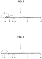
- Fig. 1 illustrates a case where the temperature of the locking portion 3 is less than or equal to a predetermined temperature.
- the insertion portion 2 of the present embodiment is composed of a member having a linear shape.
- the locking portion 3 is provided at a distal end portion 2a that is one end portion of the insertion portion 2.
- a proximal end portion 2b that is the other end portion of the insertion portion 2 is coupled to the distal end portion 4a of the linear member 4.
- the insertion portion 2 according to the present embodiment is made of a shape-memory alloy that changes shape when heated to a predetermined temperature range that exceeds a predetermined temperature.
- the locking portion 3 When the temperature of the insertion portion 2 is less than or equal to the predetermined temperature, the locking portion 3 has a shape such that the distal end portion 2a of the insertion portion 2 that is made of a shape-memory alloy that has a linear shape bends backwards.
- the locking portion 3 has a shape in which the insertion portion 2 bends at an angle of 90 or more at a position that is a predetermined length from the distal end of the insertion portion 2. That is, the locking portion 3 has a hook-like shape in a case where the temperature of the insertion portion 2 is less than or equal to a predetermined temperature.
- This kind of shape of the locking portion 3 is referred to as a "barb" or the like with respect to a fish hook or an arrowhead.
- bent portion of the locking portion 3 is substantially a V-shape
- the bent portion may be substantially a U-shape that is rounded.
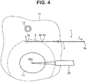
- Fig. 3 is a schematic diagram illustrating the manner in which thermal therapy is performed on tissue of an organism that includes tumor cells.
- Fig. 3 illustrates a cross-section of certain tissue 10 of an organism such as a human, and a target site 11 that is composed of tumor cells or the like as a therapy object exists at the cross-section in question.
- the object of thermal therapy may be a malignant tumor such as pancreatic cancer, hepatic cancer, renal cancer, lung cancer, prostatic cancer or malignant lymphoma, or may be a benign tumor such as uterine myoma or endometriosis.
- the target site 11 is heated by a thermal therapy instrument 20 that is inserted into the tissue 10 or by the thermal therapy instrument 20 that is disposed outside of the tissue 10.
- the thermal therapy instrument 20 is an apparatus that causes the tissue 10 to generate heat by application of a high-frequency voltage such as microwaves or radio waves or by irradiation of ultrasound.
- a high-frequency voltage such as microwaves or radio waves or by irradiation of ultrasound.
- the insertion portion 2 of the heat monitoring instrument 1 is inserted into the tissue 10, and the locking portion 3 is disposed at a location at which it is desired to detect the state of a change in temperature inside the tissue 10.
- the location at which the locking portion 3 is disposed so as to detect the state of a change in temperature inside the tissue 10 is between the distal end portion 20a of the thermal therapy instrument 20 and a blood vessel 12.
- the location at which the locking portion 3 is disposed is not limited thereto, and may be a boundary portion between the target site 11 that is the tumor cells and the healthy cells, or may be inside the target site 11.
- the tissue 10 around the distal end portion 20a of the thermal therapy instrument 20 When the thermal therapy instrument 20 is actuated to start thermal therapy, the tissue 10 around the distal end portion 20a of the thermal therapy instrument 20 generates heat. Because heat that is generated by operation of the thermal therapy instrument 20 is transmitted to the surrounding tissue 10, a region in which the temperature of the tissue 10 exceeds the predetermined temperature (42°C to 45°C) spreads to the surrounding area as time passes from the start of thermal therapy. In Fig. 4 , a region in which the temperature of the tissue 10 exceeds the predetermined temperature is indicated by a dashed line.
- the locking portion 3 changes shape and the engagement between the locking portion 3 and the tissue 10 is released. Consequently, in a case where a tensile force T is applied to the proximal end portion 4b side of the linear member 4 and a force is applied to the insertion portion 2 in a direction to withdraw the insertion portion 2 from inside the tissue 10, the insertion portion 2 drops out from the tissue 10.
- the insertion portion 31 of the ultrasound endoscope 30 is inserted into the stomach 14, and under observation by means of an optical image and an ultrasound image using the ultrasound endoscope 30, the insertion portion 2 of the heat monitoring instrument 1 is inserted from inside the stomach 14 into the tissue 10 of the pancreas 13.
- the insertion portion 2 is disposed between the target site 11 and the blood vessel 12.
- the liner member 4 extends to outside the body of the subject via a conduit provided in the ultrasound endoscope 30.
- the conduit through which the linear member 4 is inserted until the linear member 4 exits to outside the body of the subject may be the treatment instrument channel 34 through which the thermal therapy instrument 20 is inserted, or may be a conduit that is provided in the ultrasound endoscope 30 separately from the treatment instrument channel 34. Further, the conduit through which the linear member 4 is inserted may be a cylindrical member that is inserted inside the subject separately from the ultrasound endoscope 30.
- the thermal therapy instrument 20 is protruded from the distal-end-side opening portion 34a that is provided in the distal end portion 31a of the insertion portion 31.
- the thermal therapy instrument 20 is inserted into the tissue 10 of the pancreas 13 from inside the stomach 14, and thermal therapy that heats the tumor cells 11 is started.
- a weight 7 is fixed to the linear member 4 that extends as far as the inside of the stomach 14.
- a tensile force T is applied to the linear member 4 as a result of the weight 7 being fixed to the linear member 4. That is, the weight 7 is a pulling apparatus that produces a force in a direction to withdraw the insertion portion 2 of the heat monitoring instrument 1 from the tissue 10.
- the weight 7 may also be integrated with the proximal end portion 4b of the linear member 4.
- the heat monitoring instrument 1 when performing thermal therapy, by using the heat monitoring instrument 1 the user can easily and reliably know the state of an increase in the temperature of tissue at a desired location during performance of the thermal therapy. Further, because the heat monitoring instrument 1 of the present embodiment has a simple structure in which the locking portion 3 is provided in the insertion portion 2 that is made of a shape-memory alloy, and the linear member 4 is coupled to the insertion portion 2, the heat monitoring instrument 1 can be manufactured at a low cost.
- the heat monitoring instrument 1 of the present embodiment can also be used to allow a user to perceive whether or not tissue is heated to a temperature that exceeds the predetermined temperature by thermal therapy in order to determine whether or not thermal therapy has been sufficiently performed.
- a location at which the locking portion 3 is disposed inside the tissue 10 is not limited to the above described embodiment, and may be appropriately decided according to the use.
- Fig. 7 is a view illustrating a first modification of the insertion portion 2 and the locking portion 3.
- the distal end portion 2a of the insertion portion 2 that is made of a linear shape-memory alloy has a shape which is wound in a coil shape.
- the locking portion 3 changes shape to become a rectilinear shape.
- Fig. 9 is a view that illustrates a third modification of the insertion portion 2 and the locking portion 3.
- the distal end portion 2a of the insertion portion 2 of the present embodiment is divided into a plurality of portions, and the locking portion 3 is provided on each of the distal end portions 2a.
- the locking portion 3 of the present embodiment is constituted by a material that melts or softens in a case where the material is heated to a predetermined temperature range that exceeds a predetermined temperature.
- the material constituting the locking portion 3 is, for example, beeswax, bone wax or paraffin.
- the locking portion 3 in a case where the locking portion 3 is heated to the predetermined temperature range that exceeds the predetermined temperature and a force in a withdrawing direction is applied to the insertion portion 2, the locking portion 3 changes shape in accordance with the force, and consequently the engagement between the locking portion 3 and the tissue 10 is released.
- the cylindrical member 5 is a hollow tubular member, and it is possible to insert the insertion portion 2, the locking portion 3 and the linear member 4 through the inside thereof.
- the cylindrical member 5 is a needle tube having a shape that is diagonally cut in the longitudinal direction to make it easy for the distal end portion 5a to pierce the tissue 10 of the organism.
- the proximal end portion 4b of the linear member 4 extends to the outside from the proximal end portion of the cylindrical member 5.
- the distal end portion 5a of the cylindrical member 5 may also be a shape that is cut at a face that is perpendicular to the longitudinal direction.
- the form of the insertion portion 2 and the locking portion 3 is not limited to a form in which the locking portion 3 is a hook shape as shown in the drawing, and may be a form of a modification described referring to Fig. 7 to Fig. 10 in the first embodiment.
- the insertion portion 2 and the locking portion 3 are inserted into the tissue 10 using the cylindrical member 5, an operation to dispose the insertion portion 2 and the locking portion 3 at a predetermined location of the tissue 10 is facilitated.
- the locking portion 3 in a state in which the locking portion 3 is contained inside the cylindrical member 5, the locking portion 3 elastically changes shape to a shape that fits within the inner diameter of the cylindrical member 5.
- the locking portion 3 expands based on the elasticity thereof when the locking portion 3 is brought outside of the cylindrical member 5 inside the tissue 10, and returns to a shape that engages with the tissue 6 as shown in Fig. 7 and Fig. 8 .
- the heat monitoring instrument 1 when performing thermal therapy, by using the heat monitoring instrument 1 the user can easily and reliably know the state of an increase in the temperature of tissue at a desired location during performance of the thermal therapy. Further, because the heat monitoring instrument 1 has a simple structure, the heat monitoring instrument 1 can be manufactured at a low cost.
- cylindrical member 5 has the form of a needle tube
- the form of the cylindrical member 5 is not limited thereto.
- the cylindrical member 5 may also be of a form that includes a plurality of conduits.
- the cylindrical member 5 includes two conduits 5b and 5c.
- the heat monitoring instrument 1 is inserted through one of the conduits, i.e. the conduit 5b, and the thermal therapy instrument 20 is inserted through the other conduit, i.e. the conduit 5c.
- the cylindrical member 5 may be of a form that includes two conduits 5b and 5c, in which the heat monitoring instrument 1 is inserted through the conduit 5b, and the insertion portion 31 of the ultrasound endoscope 30 is inserted through the conduit 5c.
- a cylindrical member through which the ultrasound endoscope 30 is inserted in this manner is referred to as an "overtube" or the like.
- the locking portion 3 If the locking portion 3 is heated from the state in which the temperature thereof is the predetermined temperature up to the predetermined temperature range that exceeds the predetermined temperature, as shown by a chain double-dashed line in Fig. 20 , the locking portion 3 changes shape to become a rectilinear shape. Hence, in a case where the locking portion 3 is heated up to the predetermined temperature range from the state in which the temperature thereof is less than or equal to the predetermined temperature, the locking portion 3 changes shape to become a rectilinear shape to thereby release the engagement with the cylindrical member 5.
- the locking portion 3 changes shape and the engagement between the locking portion 3 and the cylindrical member 5 is released and the insertion portion 2 drops out from the cylindrical member 5.
- the user can determine that the tissue 10 at the location at which the locking portion 3 had been disposed is heated to the predetermined temperature range.
- a pulling apparatus 40 that applies the tensile force T to the linear member 4 when using the heat monitoring instrument 1 described in the first to third embodiments when performing thermal therapy will be described.
- Fig. 22 it is assumed that thermal therapy is performed on the subject using the ultrasound endoscope 30 and the thermal therapy instrument 20.
- the proximal end portion 4b of the linear member 4 of the heat monitoring instrument 1 extends from the proximal-end-side opening portion 34b through the treatment instrument channel 34 that is a conduit provided in the ultrasound endoscope 30.
- the pulling apparatus 40 is fixed to the proximal-end-side opening portion 34b of the treatment instrument channel 34 of the ultrasound endoscope 30.
- the base portion 41 is a member that is fixed to the proximal-end-side opening portion 34b.
- a through-hole 41a is formed in the base portion 41.
- an end 41b of the through-hole 41a faces the proximal-end-side opening portion 34b. Accordingly, in a state in which the base portion 41 is fixed to the proximal-end-side opening portion 34b, the through-hole 41a and the treatment instrument channel 34 are connected.
- the holding portion 43 is a member that moves relatively with respect to the base portion 41 along the central axis of the through-hole 41 a together with the slider 42.
- the holding portion 43 is arranged facing another end 41c of the through-hole 41a that is provided in the base portion 41. That is, the holding portion 43 moves forward/rearward along the central axis of the through-hole 41 a so that a distance between the holding portion 43 and the other end 41c of the through-hole 41a changes.
- the urging member 44 is a member made of a spring or the like that urges the slider 42 in a direction away from the proximal-end-side opening portion 34b. In other words, the urging member 44 urges the holding portion 43 in a direction away from the other end 41c of the through-hole 41a along the central axis of the through-hole 41 a.
- the insertion portion 2 is caused to withdraw from inside the tissue 10 or inside the cylindrical member 5 by the urging force of the urging member 44.
- the holding portion 43 is moved in a direction away from the other end 41c of the through-hole 41a. Therefore, apart from observation using an optical image and an ultrasound image using the ultrasound endoscope 30, the user can confirm that the insertion portion 2 has been withdrawn from the tissue 10 or the cylindrical member 5 by looking at the movement of the holding portion 43.
- the user when performing thermal therapy, by using the heat monitoring instrument 1 the user can easily and reliably know the state of an increase in the temperature of tissue at a desired location during performance of the thermal therapy.
- a fifth embodiment of the present invention will be described hereunder.
- components that are the same as in the fourth embodiment are denoted by the same reference numerals and a description of such components is omitted as appropriate.
- the thermal therapy instrument 20 is connected to a drive apparatus 21 that drives the thermal therapy instrument 20.
- the thermal therapy instrument 20 and the drive apparatus 21 constitute a thermal therapy apparatus.
- the withdrawal detection portion 45 is electrically connected to the drive apparatus 21 of the thermal therapy instrument 20 through an electric cable 46.
- the withdrawal detection portion 45 separates from the slider 42 and enters an "off" state.
- the drive apparatus 21 stops operation of the thermal therapy instrument 20.
- Fig. 29 illustrates a state before the insertion portion 2 of the heat monitoring instrument 1 changes shape
- Fig. 30 illustrates a state after the insertion portion 2 changes shape.
- a conductor wire 8c extends from each of the pair of electrodes 8b.
- the respective conductor wires 8c are electrically connected to an unshown drive apparatus 21 of the thermal therapy instrument 20 through an electric cable.
- the drive apparatus 21 stops operation of the thermal therapy instrument 20 in a case where electrical conduction is confirmed between the pair of electrodes 8b during operation of the thermal therapy instrument 20.
- the insulating member 8d is pinched between the pair of electrodes 8b.
- the insulating member 8d is made of a material that has electrical insulating properties and melts or softens when a predetermined temperature is exceeded.
- the material constituting the insulating member 8d is, for example, beeswax, bone wax or paraffin.
- the pair of electrodes 8b are separated by the insulating member 8d that is interposed therebetween, and electricity is not conducted between the pair of electrodes 8.
- the pair of electrodes 8b come in contact with each other because of the urging force of the plate spring 8a. That is, the switch portion 8 changes shape when the temperature exceeds the predetermined temperature, and establishes electrical conduction between the pair of electrodes 8b.
- the thermal therapy apparatus of the present embodiment configured as described above automatically stops the thermal therapy instrument 20 in a case where the insertion portion 2 of the heat monitoring instrument 1 changes shape during performance of the thermal therapy. Therefore, in a case where the insertion portion 2 of the heat monitoring instrument 1 is heated such that the temperature thereof enters the predetermined temperature range that exceeds the predetermined temperature, the thermal therapy instrument 20 can be reliably stopped.
- a seventh embodiment of the present invention will be described hereunder. Hereunder, only differences with respect to the sixth embodiment are described, and components that are the same as in the sixth embodiment are denoted by the same reference numerals and a description of such components is omitted as appropriate.
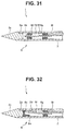
- Fig. 31 illustrates a state before the insertion portion 2 of the heat monitoring instrument 1 changes shape
- Fig. 32 illustrates a state after the insertion portion 2 changes shape.
- the electrode 8e is formed at the distal end portion of the spring member 8f.
- the spring member 8f generates a force that urges the electrode 8f in a direction to contact the inner wall face 2d of the distal end portion 2a.
- the electrode 8e is electrically connected to the unshown drive apparatus 21 of the thermal therapy instrument 20 through the spring member 8f, a conductor wire 8h that is connected to the spring member 8f, and an electric cable.
- the inner wall face 2d of the distal end portion 2a is also electrically connected to the unshown drive apparatus 21 of the thermal therapy instrument 20 through an electric cable.
- the thermal therapy apparatus of the present embodiment configured as described above automatically stops the thermal therapy instrument 20 in a case where the insertion portion 2 of the heat monitoring instrument 1 changes shape when thermal therapy is performed. Therefore, in a case where the insertion portion 2 of the heat monitoring instrument 1 is heated such that the temperature thereof enters the predetermined temperature range that exceeds the predetermined temperature, the thermal therapy instrument 20 can be reliably stopped.
- the present embodiment in comparison to the sixth embodiment, since a situation does not arise in which the melted insulating member 8d comes in contact with the subject, it is not necessary to take into consideration the biocompatibility of the insulating member 8d, and thus the degree of freedom in the selection of the material constituting the insulating member 8d is increased.
- the switch portion 8 includes a shape-changing portion 8i, the holding portion 8g, the electrode 8e and a dielectric fluid 8j.
- the shape-changing portion 8i is constituted by a shape-memory alloy that changes shape when heated to the predetermined temperature range that exceeds the predetermined temperature.
- a proximal end portion of the shape-changing portion 8i is fixed to the inside of the distal end portion 2a by the holding portion 8g.
- the holding portion 8g is made of a material having electrical insulating properties.
- the electrode 8e of the switch portion 8 and the inner wall face 2d of the distal end portion 2 enter an electrically insulated state, and if the temperature of the distal end portion 2 exceeds the predetermined temperature, the electrode 8e of the switch portion 8 and the inner wall face 2d of the distal end portion 2 enter an electrically conducting state.
- the electrode 8e is electrically connected to the unshown drive apparatus 21 of the thermal therapy instrument 20 through the shape-changing portion 8i, a conductor wire 8h that is connected to the shape-changing portion 8i, and an electric cable.
- the inner wall face 2d of the distal end portion 2a is also electrically connected to the unshown drive apparatus 21 of the thermal therapy instrument 20 through an electric cable.
- the thermal therapy apparatus of the present embodiment configured as described above automatically stops the thermal therapy instrument 20 in a case where the insertion portion 2 of the heat monitoring instrument 1 changes shape when thermal therapy is performed. Therefore, in a case where the insertion portion 2 of the heat monitoring instrument 1 is heated such that the temperature thereof enters the predetermined temperature range that exceeds the predetermined temperature, the thermal therapy instrument 20 can be reliably stopped.
- the insertion portion is composed of a tubular member in which a distal end portion is sealed, and the switch portion is arranged inside the distal end portion of the insertion portion.
- a thermal therapy apparatus that includes a heat monitoring instrument according to supplementary note 1 or 2, a thermal therapy instrument that heats the tissue, and a drive apparatus that actuates the thermal therapy instrument; wherein in a case where switching of presence/absence of electrical conduction of the switch portion of the heat monitoring instrument is detected, the drive apparatus stops operation of the thermal therapy instrument.
Landscapes
- Health & Medical Sciences (AREA)
- Life Sciences & Earth Sciences (AREA)
- Physics & Mathematics (AREA)
- Veterinary Medicine (AREA)
- Public Health (AREA)
- Engineering & Computer Science (AREA)
- Biomedical Technology (AREA)
- Heart & Thoracic Surgery (AREA)
- General Health & Medical Sciences (AREA)
- Animal Behavior & Ethology (AREA)
- Surgery (AREA)
- Molecular Biology (AREA)
- Medical Informatics (AREA)
- Pathology (AREA)
- Biophysics (AREA)
- Thermal Sciences (AREA)
- Vascular Medicine (AREA)
- Surgical Instruments (AREA)
- Measuring And Recording Apparatus For Diagnosis (AREA)
- Thermotherapy And Cooling Therapy Devices (AREA)
Abstract
Description
- The present invention relates to a heat monitoring instrument that monitors the state of an increase in the temperature of tissue of a subject when executing thermal therapy, and a thermal therapy apparatus.
- Thermal therapy is known that is performed with respect to tissue of an organism such as a human that is a subject, and that is therapy that heats the tissue. Thermal therapy, for example, causes tissue to generate heat by performing application of a high-frequency voltage such as microwaves or radio waves or by irradiation of ultrasound with respect to tissue from a thermal therapy instrument that is inserted into the body of an organism. As disclosed in, for example, Japanese Patent Application Laid-Open Publication No.
8-308853 - In the case of heating tissue by thermal therapy, heat is conveyed as far as tissue surrounding the therapy object, and it is desirable to avoid a situation in which the heating affects tissue that is not the therapy object. Consequently, a technique has been proposed that monitors the temperature of tissue using thermography or a thermocouple when executing thermal therapy.
- In the case of monitoring the temperature of tissue of a subject on which thermal therapy is performed using thermography or a thermocouple, the apparatus is complex and expensive.
- The present invention has been made in consideration of the circumstances described above, and an object of the present invention is to provide a heat monitoring instrument having a simple structure that monitors the state of an increase in the temperature of tissue of a subject when executing thermal therapy, and a thermal therapy apparatus.
- A heat monitoring instrument according to one aspect of the present invention includes: an insertion portion to be inserted into tissue of a subject; a linear member including a proximal end portion and a distal end potion, in a state in which the insertion portion is inserted into the tissue, the proximal end portion having a predetermined length that extends to outside of the tissue, and the distal end portion being coupled to the insertion portion; and a locking portion that is provided in the insertion portion and engages with the tissue when in a state of being a predetermined temperature or less, and releases engagement with the tissue by changing shape when heated from the state of being the predetermined temperature or less to a predetermined temperature range that exceeds the predetermined temperature.
- Further, a heat monitoring instrument according to another aspect of the present invention includes: a cylindrical member including a distal end side and a proximal end side, the distal end side being able to be pierced into tissue of a subject, and the proximal end side extending to outside of the tissue in a state in which the distal end side is pierced into the tissue; an insertion portion to be inserted into the cylindrical member; a linear member including a distal end portion and a proximal end portion, in a state in which the cylindrical member is pierced into the tissue and the insertion portion is inserted into the cylindrical member, the proximal end portion having a predetermined length that extends to outside of the cylindrical member, and the distal end portion being coupled to the insertion portion; and a locking portion that is provided in the insertion portion and engages with the cylindrical member when in a state of being a predetermined temperature or less, and releases engagement with the cylindrical member by changing shape when heated from the state of being the predetermined temperature or less to a predetermined temperature range that exceeds the predetermined temperature.
- Further, a thermal therapy apparatus according to one aspect of the present invention includes: the heat monitoring instrument, a thermal therapy instrument that heats the tissue, and a drive apparatus that actuates the thermal therapy instrument, wherein the drive apparatus stops operation of the thermal therapy instrument in a case where fading of a tensile force that is applied to the linear member is detected by the detection portion of the heat monitoring instrument.
-
-
Fig. 1 is a view illustrating a configuration of a heat monitoring instrument according to a first embodiment; -
Fig. 2 is a view illustrating a state in which a locking portion changes shape in the heat monitoring instrument of the first embodiment; -
Fig. 3 is a schematic diagram illustrating a state in which the heat monitoring instrument of the first embodiment is inserted into tissue; -
Fig. 4 is a view illustrating the manner of performing thermal therapy using the heat monitoring instrument of the first embodiment; -
Fig. 5 is a view illustrating an example of thermal therapy; -
Fig. 6 is a view illustrating another example of thermal therapy; -
Fig. 7 is a view illustrating a first modification of an insertion portion and the locking portion of the first embodiment; -
Fig. 8 is a view illustrating a second modification of the insertion portion and the locking portion of the first embodiment; -
Fig. 9 is a view illustrating a third modification of the insertion portion and the locking portion of the first embodiment; -
Fig. 10 is a view illustrating a fourth modification of the insertion portion and the locking portion; -
Fig. 11 is a view illustrating a configuration of a heat monitoring instrument according to a second embodiment; -
Fig. 12 is a schematic diagram illustrating a state in which the heat monitoring instrument of the second embodiment is inserted into tissue; -
Fig. 13 is a view illustrating a state in which a T-shaped locking portion is housed inside a cylindrical member; -
Fig. 14 is a view illustrating a state in which a coil-shaped locking portion is housed inside a cylindrical member; -
Fig. 15 is a view illustrating the heat monitoring instrument of the second embodiment that includes a pressing member; -
Fig. 16 is a view illustrating the heat monitoring instrument of the second embodiment in which a thermal therapy instrument is configured as a pressing member; -
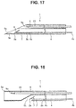
Fig. 17 is a view illustrating a first modification of the cylindrical member of the second embodiment; -
Fig. 18 is a view illustrating a second modification of the cylindrical member of the second embodiment; -
Fig. 19 is a view illustrating a third modification of the cylindrical member of the second embodiment; -
Fig. 20 is a view illustrating a heat monitoring instrument of a third embodiment; -
Fig. 21 is a schematic diagram illustrating a state in which the heat monitoring instrument of the third embodiment is inserted into tissue; -
Fig. 22 is a view illustrating a heat monitoring instrument and a pulling apparatus of a fourth embodiment; -
Fig. 23 is a cross-sectional diagram illustrating the configuration of the pulling apparatus of the fourth embodiment; -
Fig. 24 is a view illustrating a state in which a proximal end portion of a linear member is held by the pulling apparatus of the fourth embodiment; -
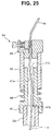
Fig. 25 is a view illustrating a state in which, in the fourth embodiment, the insertion portion of the linear member is withdrawn from tissue or a cylindrical member; -
Fig. 26 is a view illustrating a heat monitoring instrument and a pulling apparatus of a fifth embodiment; -
Fig. 27 is a cross-sectional diagram illustrating the configuration of the pulling apparatus of the fifth embodiment; -
Fig. 28 is a view illustrating a state in which a proximal end portion of the linear member is held by the pulling apparatus of the fifth embodiment; -
Fig. 29 is a view illustrating the configuration of a heat monitoring instrument according to a sixth embodiment; -
Fig. 30 is a view illustrating a state in which a switch portion changes shape in the heat monitoring instrument of the sixth embodiment; -
Fig. 31 is a view illustrating the configuration of a heat monitoring instrument according to a seventh embodiment; -
Fig. 32 is a view illustrating a state in which a switch portion changes shape in the heat monitoring instrument of the seventh embodiment; -
Fig. 33 is a view illustrating the configuration of a heat monitoring instrument according to an eighth embodiment; and -
Fig. 34 is a view illustrating a state in which a switch portion changes shape in the heat monitoring instrument of the eighth embodiment. - Preferred embodiments of the present invention are described hereunder with reference to the accompanying drawings. Note that the respective components in the respective drawings used for the following description are displayed in a contraction scale which differs according to each component so as to be shown in a size that is recognizable in the drawings, and the present invention is not limited only to the quantity of components, the shapes of components, the ratios between the sizes of components, and the relative positional relationships between the respective components illustrated in the drawings.
- A
heat monitoring instrument 1 of the present embodiment that is shown inFig. 1 is an apparatus that, when performing thermal therapy that heats predetermined tissue with respect to an organism such as a human as a subject, allows a user to perceive the state of a change in temperature in peripheral tissue accompanying the thermal therapy. - The
heat monitoring instrument 1 includes aninsertion portion 2, alocking portion 3 that is provided in theinsertion portion 2, and alinear member 4 that is coupled to theinsertion portion 2. - The
linear member 4 is an elongated member having a linear shape that is made of metal, resin, fiber or the like. The shape and material of thelinear member 4 is not particularly limited as long as thelinear member 4 is a member that withstands a tensile force (a tensile force that is applied in a longitudinal direction) of a predetermined size. For example, thelinear member 4 may be of a form that, like string, easily buckles and changes shape in a case where a compressive force is applied in the longitudinal direction. Further, for example, thelinear member 4 may be of a form that, like a piece of wire, even in a case where a compressive force is applied in the longitudinal direction, does not buckle until the compressive force exceeds a predetermined value. That is, as long as thelinear member 4 is a member that transmits a tensile force in a longitudinal direction, thelinear member 4 may be of a form that transmits a compressive force, or may be of a form that does not transmit a compressive force in the longitudinal direction. - Note that, although the thickness in the longitudinal direction of the
linear member 4 of the present embodiment that is shown in the drawings is fixed, thelinear member 4 may also have a shape in which the cross-sectional shape in the longitudinal direction changes. Further, thelinear member 4 need not be constituted by only a single member, and may be constituted by a plurality of members. For example, thelinear member 4 may have a form in which a plurality of members are present within the same cross-section, like twine, or may have a form in which a plurality of members are connected in the longitudinal direction, like a chain. - A
distal end portion 4a that is one end part of thelinear member 4 is coupled to theinsertion portion 2. Note that, thelinear member 4 and theinsertion portion 2 may also be formed integrally by a single member. - The
insertion portion 2 is a part that is inserted into tissue of an organism such as a human as the subject, or into a conduit that is provided in an endoscope or a cylindrical member that can be introduced into the body of an organism, such as a needle tube that can be pierced into the tissue of an organism. - The locking
portion 3 is provided in theinsertion portion 2. As described later, the external shape of theinsertion portion 2 differs between a case where the temperature thereof is less than or equal to a predetermined temperature and a case where the temperature thereof is in a predetermined temperature range that exceeds the predetermined temperature. Note that, it is sufficient that theinsertion portion 2 has a structure that changes shape in a case where theinsertion portion 2 is heated from a state of the predetermined temperature or less to a temperature in the predetermined temperature range, and theinsertion portion 2 need not change shape in a case where the temperature thereof falls from the state in the predetermined temperature range to the predetermined temperature or less. That is, a change in shape caused by a change in the temperature of theinsertion portion 2 may be irreversible. - In a case where the
insertion portion 2 is inserted into the tissue of an organism and the temperature of theinsertion portion 2 is less than or equal to the predetermined temperature, the lockingportion 3 engages with the surrounding tissue. In this case, if a force in a direction to withdraw theinsertion portion 2 from inside the tissue is applied to theinsertion portion 2, the lockingportion 3 generates a resistance force that retains theinsertion portion 2 inside the tissue against the aforementioned force. Further, in a case where theinsertion portion 2 is inserted to a predetermined position inside the cylindrical member and the temperature of the lockingportion 3 is less than or equal to the predetermined temperature, the lockingportion 3 engages with an engagement portion that is provided in the cylindrical member. If a force in a direction to withdraw theinsertion portion 2 from inside the tissue is applied to theinsertion portion 2, the lockingportion 3 generates a resistance force that retains theinsertion portion 2 inside the cylindrical member against the aforementioned force. - That is, in a case where the
insertion portion 2 is inserted inside tissue or into the cylindrical member and the temperature of theinsertion portion 2 is less than or equal to a predetermined temperature, even if a tensile force is applied to thelinear member 4 by pulling the proximal end side of thelinear member 4, because the lockingportion 3 is engaged with the tissue or the cylindrical member, theinsertion portion 2 stays inside the tissue or inside the cylindrical member. Note that, if an excessive tensile force of an extent such that the lockingportion 3, the tissue or the cylindrical member deforms greatly or breaks is applied to thelinear member 4, naturally theinsertion portion 2 will drop out. - Further, in a case where the
insertion portion 2 is inserted into tissue of an organism and theinsertion portion 2 is heated from a state of the predetermined temperature or less to the predetermined temperature range, theinsertion portion 2 changes shape and the locking function of the lockingportion 3 disappears, and the engagement between the lockingportion 3 and the tissue or the cylindrical member is released. - That is, in a case where the
insertion portion 2 is inserted into tissue or into the cylindrical member, and theinsertion portion 2 is heated to the predetermined temperature range, if a tensile force is applied to thelinear member 4 by pulling the proximal end side of thelinear member 4, theinsertion portion 2 will come out from inside the tissue or inside the cylindrical member. - Next, a specific configuration of the
insertion portion 2 and the lockingportion 3 will be described. As one example according to the present embodiment, theinsertion portion 2 has a form that is to be inserted into tissue of an organism such as a human that is the subject.Fig. 1 illustrates a case where the temperature of the lockingportion 3 is less than or equal to a predetermined temperature. - As shown in
Fig. 1 , theinsertion portion 2 of the present embodiment is composed of a member having a linear shape. The lockingportion 3 is provided at adistal end portion 2a that is one end portion of theinsertion portion 2. Aproximal end portion 2b that is the other end portion of theinsertion portion 2 is coupled to thedistal end portion 4a of thelinear member 4. Theinsertion portion 2 according to the present embodiment is made of a shape-memory alloy that changes shape when heated to a predetermined temperature range that exceeds a predetermined temperature. - When the temperature of the
insertion portion 2 is less than or equal to the predetermined temperature, the lockingportion 3 has a shape such that thedistal end portion 2a of theinsertion portion 2 that is made of a shape-memory alloy that has a linear shape bends backwards. - Specifically, as indicated by reference symbol θ in
Fig. 1 , the lockingportion 3 has a shape in which theinsertion portion 2 bends at an angle of 90 or more at a position that is a predetermined length from the distal end of theinsertion portion 2. That is, the lockingportion 3 has a hook-like shape in a case where the temperature of theinsertion portion 2 is less than or equal to a predetermined temperature. This kind of shape of the lockingportion 3 is referred to as a "barb" or the like with respect to a fish hook or an arrowhead. - Hence, in a case where the
insertion portion 2 is inserted inside the tissue of an organism such as a human as a subject, and the temperature of theinsertion portion 2 is less than or equal to a predetermined temperature, the lockingportion 3 that has a hook shape engages with the surrounding tissue. - Note that, although in the present embodiment that is illustrated in the drawings a bent portion of the locking
portion 3 is substantially a V-shape, the bent portion may be substantially a U-shape that is rounded. - In a case where the
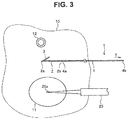
insertion portion 2 is heated from a state in which theinsertion portion 2 is a predetermined temperature to a predetermined temperature range that exceeds the predetermined temperature, as shown inFig. 2 , theinsertion portion 2 changes shape so as to eliminate the bend in theinsertion portion 2. That is, in a state in which theinsertion portion 2 is heated to the predetermined temperature range and changes shape, the lockingportion 3 runs along the longitudinal direction of theinsertion portion 2, and the lockingportion 3 and theinsertion portion 2 become a rectilinear shape. - Hence, in a case where the
insertion portion 2 is inserted into the tissue of an organism such as a human as the subject, and theinsertion portion 2 is heated from a state in which theinsertion portion 2 is the predetermined temperature or less to a temperature in the predetermined temperature range, the lockingportion 3 that is a hook shape changes shape into a rectilinear shape to thereby release the engagement with the tissue. - A value of the predetermined temperature in this case is not particularly limited, and is arbitrarily set according to the conditions under which the
heat monitoring instrument 1 is used. As one example in the present embodiment, the predetermined temperature is set from 42°C to 45°C. A predetermined temperature from 42°C to 45°C is a temperature at which tumor cells are killed, but at which healthy cells survive. Note that the predetermined temperature may also be less than 42°C or may exceed 45°C. - Next, the action of the
heat monitoring instrument 1 of the present embodiment will be described.Fig. 3 is a schematic diagram illustrating the manner in which thermal therapy is performed on tissue of an organism that includes tumor cells.Fig. 3 illustrates a cross-section ofcertain tissue 10 of an organism such as a human, and atarget site 11 that is composed of tumor cells or the like as a therapy object exists at the cross-section in question. Note that, the object of thermal therapy may be a malignant tumor such as pancreatic cancer, hepatic cancer, renal cancer, lung cancer, prostatic cancer or malignant lymphoma, or may be a benign tumor such as uterine myoma or endometriosis. - In the thermal therapy, the
target site 11 is heated by athermal therapy instrument 20 that is inserted into thetissue 10 or by thethermal therapy instrument 20 that is disposed outside of thetissue 10. In this case, thethermal therapy instrument 20 is an apparatus that causes thetissue 10 to generate heat by application of a high-frequency voltage such as microwaves or radio waves or by irradiation of ultrasound. As one example according to the present embodiment, it is assumed that tissue that is present around adistal end portion 20a of thethermal therapy instrument 20 is heated by an operation of thethermal therapy instrument 20 that is inserted inside thetarget site 11. Note that, so-called "high-intensity focused ultrasound (HIFU)" in which ultrasound is irradiated from thethermal therapy instrument 20 so as to focus on thetarget site 11 is known as a method for causing thetarget site 11 to generate heat by means of thethermal therapy instrument 20 that is disposed outside thetissue 10. The specific configuration of thethermal therapy instrument 20 is known, and a detailed description thereof is therefore omitted herein. - Before performing thermal therapy, the
insertion portion 2 of theheat monitoring instrument 1 is inserted into thetissue 10, and the lockingportion 3 is disposed at a location at which it is desired to detect the state of a change in temperature inside thetissue 10. As one example according to the present embodiment, the location at which the lockingportion 3 is disposed so as to detect the state of a change in temperature inside thetissue 10 is between thedistal end portion 20a of thethermal therapy instrument 20 and ablood vessel 12. Note that the location at which the lockingportion 3 is disposed is not limited thereto, and may be a boundary portion between thetarget site 11 that is the tumor cells and the healthy cells, or may be inside thetarget site 11. - The insertion path of the
insertion portion 2 into thetissue 10 may be a path that passes through the skin from outside the body of the subject, or a path that passes from inside the digestive tract of the subject through a tubular wall of the digestive tract, or may be a path that passes from inside a body cavity through an outer wall of an internal organ having thetissue 10. An operation to insert theinsertion portion 2 of theheat monitoring instrument 1 to a predetermined position inside thetissue 10 is performed, for example, under observation by means of an ultrasound diagnostic apparatus such as an ultrasound endoscope. - In a state in which the
insertion portion 2 of theheat monitoring instrument 1 is inserted inside thetissue 10, aproximal end portion 4b of thelinear member 4 is extended to outside of the internal organ that has thetissue 10. Theproximal end portion 4b of thelinear member 4 may also be extended as far as outside the body of the subject in a state in which theinsertion portion 2 is inserted inside thetissue 10. - In a state in which the
insertion portion 2 of theheat monitoring instrument 1 is inserted inside thetissue 10 and the lockingportion 3 is disposed inside the tissue 10 (state shown inFig. 3 ), because the temperature of theinsertion portion 2 is lower than the predetermined temperature that is 42°C to 45°C, the lockingportion 3 engages with the surroundingtissue 10. Consequently, even in a case where a tensile force T is applied to theproximal end portion 4b side of thelinear member 4, and a force is applied to theinsertion portion 2 in a direction to withdraw theinsertion portion 2 from inside thetissue 10, the position of theinsertion portion 2 inside thetissue 10 does not change. - That is, in a case where the temperature of the
tissue 10 in which the lockingportion 3 is disposed is less than or equal to the predetermined temperature, even if thelinear member 4 that extends to outside thetissue 10 is pulled by a finger of the user or by an apparatus of some kind, theheat monitoring instrument 1 will remain inserted inside thetissue 10. In other words, in a case where theinsertion portion 2 of theheat monitoring instrument 1 does not drop out from inside thetissue 10 even when the tensile force T is applied to thelinear member 4, the user can determine that the temperature of thetissue 10 at the location at which theinsertion portion 2 is disposed is less than or equal to the predetermined temperature. - When the
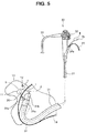
thermal therapy instrument 20 is actuated to start thermal therapy, thetissue 10 around thedistal end portion 20a of thethermal therapy instrument 20 generates heat. Because heat that is generated by operation of thethermal therapy instrument 20 is transmitted to the surroundingtissue 10, a region in which the temperature of thetissue 10 exceeds the predetermined temperature (42°C to 45°C) spreads to the surrounding area as time passes from the start of thermal therapy. InFig. 4 , a region in which the temperature of thetissue 10 exceeds the predetermined temperature is indicated by a dashed line. - Further, as shown in
Fig. 4 , when the region in which the temperature of thetissue 10 exceeds the predetermined temperature extends as far as the location at which theinsertion portion 2 is disposed, the lockingportion 3 changes shape and the engagement between the lockingportion 3 and thetissue 10 is released. Consequently, in a case where a tensile force T is applied to theproximal end portion 4b side of thelinear member 4 and a force is applied to theinsertion portion 2 in a direction to withdraw theinsertion portion 2 from inside thetissue 10, theinsertion portion 2 drops out from thetissue 10. - That is, in a case where the temperature of the
tissue 10 at which theinsertion portion 2 is disposed is heated up to the predetermined temperature range that exceeds the predetermined temperature, if thelinear member 4 that extends to outside of thetissue 10 is pulled by a finger of the user or by some kind of apparatus, theheat monitoring instrument 1 will be withdrawn from thetissue 10. In other words, in a case where the tensile force T is applied to thelinear member 4 and as a result theinsertion portion 2 of theheat monitoring instrument 1 drops out from inside thetissue 10, the user can determine that thetissue 10 at the location at which theinsertion portion 2 is disposed has been heated up to the predetermined temperature range. - An example of performing thermal therapy with respect to a
pancreas 13 that has thetissue 10 in which thetarget site 11 that is composed of tumor cells is present will now be described referring toFig. 5 . In the example illustrated inFig. 5 , in a state in which the human that is the subject reclines on the left side, anultrasound endoscope 30 is inserted into thestomach 14 that is part of the digestive tract, and thermal therapy is performed on thepancreas 13 from inside thestomach 14 using thethermal therapy instrument 20 that is protruded from adistal end portion 31a of theultrasound endoscope 30. - The configuration of the
ultrasound endoscope 30 as well as the thermal therapy that is performed using theultrasound endoscope 30 and thethermal therapy instrument 20 are known, and hence a detailed description is omitted here. - The
ultrasound endoscope 30 has aninsertion portion 31 that can be introduced into inside the subject, and anoperation portion 32 that is located at a proximal end of theinsertion portion 31. Anultrasound transducer 31b for sending and receiving ultrasound, an image pickup apparatus for picking up optical images, an illumination apparatus, and a distal-end-side opening portion 31c of atreatment instrument channel 34 and the like are provided at thedistal end portion 31a of theinsertion portion 31. - An ultrasound image obtained by driving the
ultrasound transducer 31b and an optical image obtained by driving the image pickup apparatus are displayed on an unshown image display apparatus that is connected through auniversal cord 33 that extends from theoperation portion 32. - The
treatment instrument channel 34 is a conduit that is inserted through the inside of theinsertion portion 31. A proximal-end-side opening portion 34b of thetreatment instrument channel 34 opens at theoperation portion 32. By inserting thethermal therapy instrument 20 into thetreatment instrument channel 34 from the proximal-end-side opening portion 34b, thedistal end portion 20a of thethermal therapy instrument 20 can be protruded from the distal-end-side opening portion 34a. - According to the thermal therapy shown in
Fig. 5 , theinsertion portion 31 of theultrasound endoscope 30 is inserted into thestomach 14, and under observation by means of an optical image and an ultrasound image using theultrasound endoscope 30, theinsertion portion 2 of theheat monitoring instrument 1 is inserted from inside thestomach 14 into thetissue 10 of thepancreas 13. As described above, according to the present embodiment theinsertion portion 2 is disposed between thetarget site 11 and theblood vessel 12. In this case, theliner member 4 extends to outside the body of the subject via a conduit provided in theultrasound endoscope 30. - The conduit through which the
linear member 4 is inserted until thelinear member 4 exits to outside the body of the subject may be thetreatment instrument channel 34 through which thethermal therapy instrument 20 is inserted, or may be a conduit that is provided in theultrasound endoscope 30 separately from thetreatment instrument channel 34. Further, the conduit through which thelinear member 4 is inserted may be a cylindrical member that is inserted inside the subject separately from theultrasound endoscope 30. - A tensile force T can be applied to the
linear member 4 that is extended to outside the body of the subject, by, for example, the user using a finger to grasp theproximal end portion 4b. Further, for example, a tensile force T can be applied to thelinear member 4 by a method that fixes a weight having a predetermined weight to theproximal end portion 4b, or by a method that connects a pulling apparatus that uses a spring, an electric motor or the like to theproximal end portion 4b. - Further, the
thermal therapy instrument 20 is protruded from the distal-end-side opening portion 34a that is provided in thedistal end portion 31a of theinsertion portion 31. Thethermal therapy instrument 20 is inserted into thetissue 10 of thepancreas 13 from inside thestomach 14, and thermal therapy that heats thetumor cells 11 is started. - Subsequently, upon the temperature of the
insertion portion 2 being heated up to the predetermined temperature range that exceeds the predetermined temperature as a result of heat of the thermal therapy being transmitted to the surrounding area, theinsertion portion 2 changes shape and the engagement between the lockingportion 3 and thetissue 10 is released, and consequently theinsertion portion 2 drops out from thetissue 10. Withdrawal of theinsertion portion 2 from thetissue 10 can be confirmed, for example, by observation by means of an optical image and an ultrasound image using theultrasound endoscope 30. In a case where thelinear member 4 is pulled by a finger of the user, the user can directly perceive withdrawal of theinsertion portion 2 from thetissue 10 as a result of the tensile force that was being applied to thelinear member 4 fading. By confirming the withdrawal of theinsertion portion 2 from thetissue 10, the user can determine that thetissue 10 at the location at which theinsertion portion 2 had been disposed is heated to the predetermined temperature range. - In this connection, although according to the example illustrated in
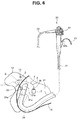
Fig. 5 theproximal end portion 4b of thelinear member 4 extends to outside the body of the subject in a state in which theinsertion portion 2 of theheat monitoring instrument 1 is inserted inside thetissue 10 of thepancreas 13, as illustrated as one example inFig. 6 , a form may also be adopted in which theproximal end portion 4b of thelinear member 4 extends to inside the body of the subject (into the stomach 14). - In the example illustrated in
Fig. 6 , theinsertion portion 31 of theultrasound endoscope 30 is inserted into thestomach 14, and under observation by means of an optical image and an ultrasound image using theultrasound endoscope 30, theinsertion portion 2 of theheat monitoring instrument 1 is inserted into thetissue 10 of thepancreas 13 from inside thestomach 14. As described above, in the present embodiment theinsertion portion 2 is disposed between thetumor cells 11 and theblood vessel 12. In this case, theproximal end portion 4b of thelinear member 4 extends as far as the inside of thestomach 14. - A
weight 7 is fixed to thelinear member 4 that extends as far as the inside of thestomach 14. A tensile force T is applied to thelinear member 4 as a result of theweight 7 being fixed to thelinear member 4. That is, theweight 7 is a pulling apparatus that produces a force in a direction to withdraw theinsertion portion 2 of theheat monitoring instrument 1 from thetissue 10. Note that, theweight 7 may also be integrated with theproximal end portion 4b of thelinear member 4. - The
thermal therapy instrument 20 is then protruded from the distal-end-side opening portion 34a that is provided in thedistal end portion 31a of theinsertion portion 31, thethermal therapy instrument 20 is inserted into thetissue 10 of thepancreas 13 from inside thestomach 14, and the thermal therapy for heating thetarget site 11 is started. - Subsequently, upon the temperature of the locking
portion 3 being heated to the predetermined temperature range that exceeds the predetermined temperature as a result of the heat of the thermal therapy being transmitted to the surrounding area, the lockingportion 3 changes shape and the engagement between the lockingportion 3 and thetissue 10 is released, and consequently theinsertion portion 2 drops out from thetissue 10. Withdrawal of theinsertion portion 2 from thetissue 10 can be confirmed, for example, by observation by means of an optical image and an ultrasound image using theultrasound endoscope 30. By confirming withdrawal of theinsertion portion 2 from thetissue 10, the user can determine that thetissue 10 at the location at which theinsertion portion 2 is disposed is heated up to the predetermined temperature range. - As described above, according to the present embodiment, when performing thermal therapy, by using the
heat monitoring instrument 1 the user can easily and reliably know the state of an increase in the temperature of tissue at a desired location during performance of the thermal therapy. Further, because theheat monitoring instrument 1 of the present embodiment has a simple structure in which the lockingportion 3 is provided in theinsertion portion 2 that is made of a shape-memory alloy, and thelinear member 4 is coupled to theinsertion portion 2, theheat monitoring instrument 1 can be manufactured at a low cost. - For example, in a case where the locking
portion 3 is disposed between thetarget site 11 and theblood vessel 12 as in the present embodiment and thermal therapy is performed while applying the tensile force T to thelinear member 4, if the thermal therapy is stopped when theinsertion portion 2 comes out from thetissue 10, it is possible to prevent theblood vessel 12 from being heated to a temperature that exceeds the predetermined temperature. As described above, because the predetermined temperature is a temperature at which tumor cells are killed and healthy cells survive, the heating by the thermal therapy does not affect theblood vessel 12. Thus, by using theheat monitoring instrument 1 in thermal therapy that kills tumor cells, heating by the thermal therapy can be prevented from affecting normal tissue around thetarget site 11 that is composed of the tumor cells. - Note that, in addition to the above described use, the
heat monitoring instrument 1 of the present embodiment can also be used to allow a user to perceive whether or not tissue is heated to a temperature that exceeds the predetermined temperature by thermal therapy in order to determine whether or not thermal therapy has been sufficiently performed. Hence, when using theheat monitoring instrument 1, a location at which the lockingportion 3 is disposed inside thetissue 10 is not limited to the above described embodiment, and may be appropriately decided according to the use. - For example, if the locking
portion 3 is disposed in the vicinity of the outside of thetarget site 11, if theinsertion portion 2 drops out the user can determine that theentire target site 11 is heated to a temperature at which tumor cells are killed. - Further, for example, if the
tissue 10 in which thetarget site 11 is present is a site that is sensitive to heating, such as the pancreas, in some cases it is desired to prevent healthy tissue on the outside of thetarget site 11 from being heated so as to suppress side effects that are caused by thermal therapy. In this case, if the lockingportion 3 is disposed at a position in the vicinity of the outer circumference of thetarget site 11 that is a position that is inside thetarget site 11, an increase in the temperature of thetissue 10 outside thetarget site 11 can be prevented. - The
heat monitoring instrument 1 that is described above is an apparatus that perceives a temperature change in tissue of a subject by means of a change in shape of theinsertion portion 2 that is made of a shape-memory alloy. Although in the present embodiment theheat monitoring instrument 1 is used in a case of heating the tissue of a subject, theheat monitoring instrument 1 can also be used for cryotherapy that freezes the tissue of a subject. In this case, theinsertion portion 2 of theheat monitoring instrument 1 is configured so as to change shape so that engagement between the lockingportion 3 and the tissue is released if the temperature falls below a predetermined temperature, for example, 0°C. - Next, a modification of the
insertion portion 2 and the lockingportion 3 will be described. Although the above-describedlocking portion 3 is a hook-like shape, the lockingportion 3 is not limited thereto. The lockingportion 3 may be a portion having a shape that, in a case where theinsertion portion 2 is inserted into thetissue 10 of an organism and the temperature of theinsertion portion 2 is less than or equal to the predetermined temperature, produces a force that retains theinsertion portion 2 inside thetissue 10 against a force in a direction to withdraw theinsertion portion 2, and changes shape so that such a resistance force fades when the temperature of theinsertion portion 2 is heated to a predetermined temperature range that exceeds the predetermined temperature. -
Fig. 7 is a view illustrating a first modification of theinsertion portion 2 and the lockingportion 3. As shown inFig. 7 , in a case where the temperature of the lockingportion 3 of the present embodiment is less than or equal to the predetermined temperature, thedistal end portion 2a of theinsertion portion 2 that is made of a linear shape-memory alloy has a shape which is wound in a coil shape. In a case where the lockingportion 3 is heated to the predetermined temperature range that exceeds the predetermined temperature, as shown by a chain double-dashed line inFig. 7 , the lockingportion 3 changes shape to become a rectilinear shape. -
Fig. 8 is a view that illustrates a second modification of theinsertion portion 2 and the lockingportion 3. As shown inFig. 8 , in a case where the temperature of the lockingportion 3 of the present embodiment is less than or equal or to the predetermined temperature, thedistal end portion 2a of theinsertion portion 2 that is made of a linear shape-memory alloy has a shape which is bent in substantially a T-shape. Specifically, the lockingportion 3 has a shape which turns back at an angle of approximately 180 degrees at a point A that is a distance of a predetermined length L1 on the proximal end side from the distal end of theinsertion portion 2, and is further bent at an angle of approximately 90 degrees at a point B that is a distance of a length L2 which is shorter than the length L1 on the proximal end side from the point A. In a case where the lockingportion 3 is heated to the predetermined temperature range that exceeds the predetermined temperature, as shown by a chain double-dashed line inFig. 8 , the lockingportion 3 changes shape into a rectilinear shape. -
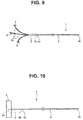
Fig. 9 is a view that illustrates a third modification of theinsertion portion 2 and the lockingportion 3. As shown inFig. 9 , thedistal end portion 2a of theinsertion portion 2 of the present embodiment is divided into a plurality of portions, and the lockingportion 3 is provided on each of thedistal end portions 2a. -
Fig. 10 is a view that illustrates a fourth modification of theinsertion portion 2 and the lockingportion 3. In the present embodiment, theinsertion portion 2 is a member having a linear shape. The lockingportion 3 is a member that is fixed to thedistal end portion 2a of theinsertion portion 2, and has an outer shape that protrudes to the sides of thedistal end portion 2a when the temperature is less than or equal to the predetermined temperature. - The locking
portion 3 of the present embodiment is constituted by a material that melts or softens in a case where the material is heated to a predetermined temperature range that exceeds a predetermined temperature. The material constituting the lockingportion 3 is, for example, beeswax, bone wax or paraffin. In the present embodiment, in a case where the lockingportion 3 is heated to the predetermined temperature range that exceeds the predetermined temperature and a force in a withdrawing direction is applied to theinsertion portion 2, the lockingportion 3 changes shape in accordance with the force, and consequently the engagement between the lockingportion 3 and thetissue 10 is released. - Even in the case of the modifications illustrated in
Fig. 7 to Fig. 10 , as described above, when performing thermal therapy, by using theheat monitoring instrument 1 the user can easily and reliably know the state of an increase in the temperature of tissue at a desired location during performance of the thermal therapy. Further, because theheat monitoring instrument 1 according to these modifications has a simple structure in which the lockingportion 3 is fixed to the distal end portion of a member having a linear shape, theheat monitoring instrument 1 can be manufactured at a low cost. - A second embodiment of the present invention will be described hereunder. Hereunder, only differences with respect to the first embodiment are described, and components that are the same as in the first embodiment are denoted by the same reference numerals and a description of such components is omitted as appropriate.
- As shown in
Fig. 11 , theheat monitoring instrument 1 of the present embodiment differs from the first embodiment in that theheat monitoring instrument 1 of the present embodiment includes acylindrical member 5. - The
cylindrical member 5 is a hollow tubular member, and it is possible to insert theinsertion portion 2, the lockingportion 3 and thelinear member 4 through the inside thereof. As one example according to the present embodiment, thecylindrical member 5 is a needle tube having a shape that is diagonally cut in the longitudinal direction to make it easy for thedistal end portion 5a to pierce thetissue 10 of the organism. Theproximal end portion 4b of thelinear member 4 extends to the outside from the proximal end portion of thecylindrical member 5. Note that thedistal end portion 5a of thecylindrical member 5 may also be a shape that is cut at a face that is perpendicular to the longitudinal direction. - In the present embodiment, the form of the
insertion portion 2 and the lockingportion 3 is not limited to a form in which the lockingportion 3 is a hook shape as shown in the drawing, and may be a form of a modification described referring toFig. 7 to Fig. 10 in the first embodiment. - When using the
heat monitoring instrument 1 of the present embodiment, thecylindrical member 5 is pierced into thetissue 10 in a state in which theinsertion portion 2 and lockingportion 3 are contained inside thecylindrical member 5, and thereafter, as shown inFig. 12 , theinsertion portion 2 and the lockingportion 3 are disposed inside thetissue 10 by moving thecylindrical member 5 to the proximal end side relative to theinsertion portion 2, the lockingportion 3 and thelinear member 4. Note that, thecylindrical member 5 may be of a form that moves relatively by the amount of only a predetermined distance towards the proximal end side from the distal end portion 3a of the lockingportion 3, or may be of a form that moves relatively as far as theproximal end portion 4b of thelinear member 4 so that theinsertion portion 2, the lockingportion 3 and thelinear member 4 come out from the inside of thecylindrical member 5. - Thus, according to the present embodiment, because the
insertion portion 2 and the lockingportion 3 are inserted into thetissue 10 using thecylindrical member 5, an operation to dispose theinsertion portion 2 and the lockingportion 3 at a predetermined location of thetissue 10 is facilitated. - For example, in a case where the shape of the locking
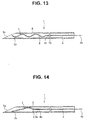
portion 3 is the coil shape shown inFig. 7 or the T-shape shown inFig. 8 , because there is a large amount of resistance when theinsertion portion 2 is inserted into thetissue 10 in a state in which the lockingportion 3 is exposed, insertion of theinsertion portion 2 as far as a deep position is difficult. According to the present embodiment, as shown inFig. 13 and Fig. 14 , by housing the lockingportion 3 that is a T-shape or a coil shape inside thecylindrical member 5, it is possible to easily insert theinsertion portion 2 and the lockingportion 3 as far as a predetermined location in thetissue 10. - In the embodiment shown in
Fig. 13 and inFig. 14 , in a state in which the lockingportion 3 is contained inside thecylindrical member 5, the lockingportion 3 elastically changes shape to a shape that fits within the inner diameter of thecylindrical member 5. The lockingportion 3 expands based on the elasticity thereof when the lockingportion 3 is brought outside of thecylindrical member 5 inside thetissue 10, and returns to a shape that engages with thetissue 6 as shown inFig. 7 and Fig. 8 . - In the present embodiment also, similarly to the first embodiment, when performing thermal therapy, by using the
heat monitoring instrument 1 the user can easily and reliably know the state of an increase in the temperature of tissue at a desired location during performance of the thermal therapy. Further, because theheat monitoring instrument 1 has a simple structure, theheat monitoring instrument 1 can be manufactured at a low cost. - Note that, as long as the
linear member 4 is of a form that does not easily buckle with respect to a compressive force in the longitudinal direction, as in the case of, for example, a metal wire, an operation to move thecylindrical member 5 to the proximal end side relative to theinsertion portion 2, the lockingportion 3 and thelinear member 4 inside thetissue 10 can be easily performed by merely pulling thecylindrical member 5 in the proximal end direction while keeping thelinear member 4 fixed. - However, in a case where the
linear member 4 has a flexible form such as string, an operation is required to push out theinsertion portion 2 and the lockingportion 3 relatively from inside thecylindrical member 5 to the distal end side. Therefore, in a case where thelinear member 4 has a flexible form such as string, as shown inFig. 15 , a pressingmember 6 is arranged inside thecylindrical member 5. Thepressing member 6 is a member that is longer than thecylindrical member 5, and has an outer diameter that is smaller than the inner diameter of thecylindrical member 5. Thepressing member 6 has stiffness such that thepressing member 6 does not buckle even if a force of an amount required for pushing out theinsertion portion 2 and the lockingportion 3 from inside thecylindrical member 5 into thetissue 10 is applied in the axial direction. Note that, as shown inFig. 16 , thethermal therapy instrument 20 that is inserted through the inside of thecylindrical member 5 may also be used as the pressingmember 6. - Although in the present embodiment that is described above the
cylindrical member 5 has the form of a needle tube, the form of thecylindrical member 5 is not limited thereto. - For example, as shown as a first modification in
Fig. 17 , thecylindrical member 5 may also be of a form that includes a plurality of conduits. According to the present modification that is illustrated inFig. 17 , thecylindrical member 5 includes twoconduits heat monitoring instrument 1 is inserted through one of the conduits, i.e. theconduit 5b, and thethermal therapy instrument 20 is inserted through the other conduit, i.e. theconduit 5c. - As shown as a second modification in
Fig. 18 , in a case where thecylindrical member 5 has a plurality of conduits, the opening portions on the distal end side of the respective conduits may be provided apart from each other in the longitudinal direction of thecylindrical member 5. In the present modification illustrated inFig. 18 , thecylindrical member 5 has aconduit 5b through which theheat monitoring instrument 1 is inserted, and aconduit 5c through which thethermal therapy instrument 20 is inserted. Theconduit 5c opens at the distal end of thecylindrical member 5, and theconduit 5b opens at a position on the proximal end side that is separated from the distal end of thecylindrical member 5 by a predetermined distance. - Further, for example, as shown as a third modification in
Fig. 19 , thecylindrical member 5 may be of a form that includes twoconduits heat monitoring instrument 1 is inserted through theconduit 5b, and theinsertion portion 31 of theultrasound endoscope 30 is inserted through theconduit 5c. A cylindrical member through which theultrasound endoscope 30 is inserted in this manner is referred to as an "overtube" or the like. - Even in the case of the modifications illustrated in
Fig. 17 to Fig. 19 , as described above, when performing thermal therapy, by using theheat monitoring instrument 1 the user can easily and reliably know the state of an increase in the temperature of tissue at a desired location during performance of the thermal therapy. Further, because theheat monitoring instrument 1 according to these modifications has a simple structure, theheat monitoring instrument 1 can be manufactured at a low cost. - A third embodiment of the present invention will be described hereunder. Hereunder, only differences with respect to the first and second embodiments are described, and components that are the same as in the first and second embodiments are denoted by the same reference numerals and a description of such components is omitted as appropriate.
- In the foregoing first and second embodiments, in a case where the
insertion portion 2 of theheat monitoring instrument 1 is inserted inside thetissue 10 and the temperature is less than or equal to the predetermined temperature, the lockingportion 3 engages with the surroundingtissue 10. In contrast, according to the present embodiment, in a case where theinsertion portion 2 of theheat monitoring instrument 1 is inserted inside thecylindrical member 5 and the temperature is less than or equal to the predetermined temperature, the lockingportion 3 engages with thecylindrical member 5. - As shown in
Fig. 20 , theheat monitoring instrument 1 includes thecylindrical member 5, and theinsertion portion 2 andlinear member 4 that are inserted through the inside of thecylindrical member 5. The lockingportion 3 is provided at thedistal end portion 2a of theinsertion portion 2. - As one example according to the present embodiment, the
cylindrical member 5 is a needle tube that can be pierced into thetissue 10. A through-hole 5d is formed in the wall face in the vicinity of thedistal end portion 5a of thecylindrical member 5. - Similarly to the first and second embodiments, the
linear member 4 is an elongated member having a linear shape that is made of metal, synthetic resin or the like. - The
insertion portion 2 is composed of a member having a linear shape. The lockingportion 3 is provided at thedistal end portion 2a that is one end portion of theinsertion portion 2. Theproximal end portion 2b that is the other end portion of theinsertion portion 2 is coupled to thedistal end portion 4a of thelinear member 4. Theinsertion portion 2 of the present embodiment is made of a shape-memory alloy that changes shape into a rectilinear shape when heated to a predetermined temperature range that exceeds a predetermined temperature. Note that, thelinear member 4 and theinsertion portion 2 may also be formed integrally by a single member. - The locking
portion 3 is formed by bending thedistal end portion 2a of theinsertion portion 2 that is made of a linear shape-memory alloy into a hook shape in a state in which the temperature of theinsertion portion 2 is less than or equal to the predetermined temperature. The lockingportion 3 protrudes to the outside of thecylindrical member 5 through the through-hole 5d formed in the wall face of thecylindrical member 5. Hence, in a case where the temperature of the lockingportion 3 is less than or equal to a predetermined temperature, the lockingportion 3 engages with thecylindrical member 5. - Further, in a state in which the locking
portion 3 is engaged in the through-hole 5d of thecylindrical member 5, theproximal end portion 4b of thelinear member 4 extends to the outside from the proximal end of thecylindrical member 5. - If the locking
portion 3 is heated from the state in which the temperature thereof is the predetermined temperature up to the predetermined temperature range that exceeds the predetermined temperature, as shown by a chain double-dashed line inFig. 20 , the lockingportion 3 changes shape to become a rectilinear shape. Hence, in a case where the lockingportion 3 is heated up to the predetermined temperature range from the state in which the temperature thereof is less than or equal to the predetermined temperature, the lockingportion 3 changes shape to become a rectilinear shape to thereby release the engagement with thecylindrical member 5. - When using the
heat monitoring instrument 1 of the present embodiment when performing thermal therapy, as shown inFig. 21 , thecylindrical member 5 of theheat monitoring instrument 1 is inserted into thetissue 10, and the lockingportion 3 is disposed at a location at which it is desired to detect the state of a change in temperature inside thetissue 10. As one example according to the present embodiment, the location at which the lockingportion 3 is disposed so as to detect the state of a change in temperature inside thetissue 10 is between thedistal end portion 20a of thethermal therapy instrument 20 and ablood vessel 12. Note that, the location at which the lockingportion 3 is disposed is not limited thereto, and may be a boundary portion between thetarget site 11 that is the tumor cells and the healthy cells, or may be inside thetarget site 11. - The insertion path of the
cylindrical member 5 into thetissue 10 may be a path that passes through the skin from outside the body of the subject, or a path that passes from inside the digestive tract of the subject through a tubular wall of the digestive tract, or a path that passes from inside a body cavity through an outer wall of an internal organ having thetissue 10. An operation to insert thecylindrical member 5 to a predetermined position inside thetissue 10 is performed, for example, under observation by means of an ultrasound diagnostic apparatus such as theultrasound endoscope 30. Similarly to the first and second embodiments, a tensile force T is applied by means of a finger of the user or by a pulling apparatus of some kind (for example, a weight 7) to thelinear member 4. - When the
thermal therapy instrument 20 is operated and the temperature of the lockingportion 3 is heated to the predetermined temperature range that exceeds the predetermined temperature as a result of the heat of the thermal therapy being transmitted to the surrounding area, the lockingportion 3 changes shape and the engagement between the lockingportion 3 and thecylindrical member 5 is released and theinsertion portion 2 drops out from thecylindrical member 5. By confirming the withdrawal of theinsertion portion 2 from thecylindrical member 5, the user can determine that thetissue 10 at the location at which the lockingportion 3 had been disposed is heated to the predetermined temperature range. - As described above, according to the present embodiment, when performing thermal therapy, by using the
heat monitoring instrument 1 the user can easily and reliably know the state of an increase in the temperature of tissue at a desired location during performance of the thermal therapy. Further, because theheat monitoring instrument 1 of the present embodiment has a simple structure, theheat monitoring instrument 1 can be manufactured at a low cost. - A fourth embodiment of the present invention will be described hereunder. Hereunder, only differences with respect to the first to third embodiments are described, and components that are the same as in the first to third embodiments are denoted by the same reference numerals and a description of such components is omitted as appropriate.
- In the present embodiment, a pulling
apparatus 40 that applies the tensile force T to thelinear member 4 when using theheat monitoring instrument 1 described in the first to third embodiments when performing thermal therapy will be described. As one example according to the present embodiment, as shown inFig. 22 , it is assumed that thermal therapy is performed on the subject using theultrasound endoscope 30 and thethermal therapy instrument 20. - The
proximal end portion 4b of thelinear member 4 of theheat monitoring instrument 1 extends from the proximal-end-side opening portion 34b through thetreatment instrument channel 34 that is a conduit provided in theultrasound endoscope 30. The pullingapparatus 40 is fixed to the proximal-end-side opening portion 34b of thetreatment instrument channel 34 of theultrasound endoscope 30. - As shown in
Fig. 23 , the pullingapparatus 40 has a configuration that includes abase portion 41, aslider 42, a holdingportion 43 and an urgingmember 44. - The
base portion 41 is a member that is fixed to the proximal-end-side opening portion 34b. A through-hole 41a is formed in thebase portion 41. In a state in which thebase portion 41 is fixed to the proximal-end-side opening portion 34b, anend 41b of the through-hole 41a faces the proximal-end-side opening portion 34b. Accordingly, in a state in which thebase portion 41 is fixed to the proximal-end-side opening portion 34b, the through-hole 41a and thetreatment instrument channel 34 are connected. - The
slider 42 is a member that moves relatively with respect to thebase portion 41. Theslider 42 moves relatively with respect to thebase portion 41 along the central axis of the through-hole 41a. The holdingportion 43 is fixed to theslider 42. - The holding
portion 43 is a member that moves relatively with respect to thebase portion 41 along the central axis of the through-hole 41 a together with theslider 42. The holdingportion 43 is arranged facing anotherend 41c of the through-hole 41a that is provided in thebase portion 41. That is, the holdingportion 43 moves forward/rearward along the central axis of the through-hole 41 a so that a distance between the holdingportion 43 and theother end 41c of the through-hole 41a changes. - The holding
portion 43 has a structure that holds theproximal end portion 4b of thelinear member 4. Holding of theproximal end portion 4b of thelinear member 4 by the holdingportion 43 can be released by an operation of the user. According to the present embodiment that is illustrated in the drawings, as one example the holdingportion 43 has a configuration that pinches theproximal end portion 4b of thelinear member 4 from the sides like a clip. - The urging
member 44 is a member made of a spring or the like that urges theslider 42 in a direction away from the proximal-end-side opening portion 34b. In other words, the urgingmember 44 urges the holdingportion 43 in a direction away from theother end 41c of the through-hole 41a along the central axis of the through-hole 41 a. - When performing thermal therapy, as shown in
Fig. 24 , in a state in which the holdingportion 43 is brought near to the other end of theother end 41c of the through-hole 41a against the urging force of the urgingmember 44, theproximal end portion 4b of thelinear member 4 that extends from the proximal-end-side opening portion 34b is held by the holdingportion 43. By this means, since the urging force of the urgingmember 44 is transmitted to thelinear member 4, the tensile force T is applied to thelinear member 4. - Further, when heating is performed such that the temperature of the locking
portion 3 of theheat monitoring instrument 1 reaches the predetermined temperature range that exceeds the predetermined temperature, because the engagement between the lockingportion 3 and thetissue 10 or thecylindrical member 5 is released, theinsertion portion 2 is caused to withdraw from inside thetissue 10 or inside thecylindrical member 5 by the urging force of the urgingmember 44. At such time, as shown inFig. 25 , the holdingportion 43 is moved in a direction away from theother end 41c of the through-hole 41a. Therefore, apart from observation using an optical image and an ultrasound image using theultrasound endoscope 30, the user can confirm that theinsertion portion 2 has been withdrawn from thetissue 10 or thecylindrical member 5 by looking at the movement of the holdingportion 43. - Thus, according to the present embodiment, similarly to the above described first to third embodiments, when performing thermal therapy, by using the
heat monitoring instrument 1 the user can easily and reliably know the state of an increase in the temperature of tissue at a desired location during performance of the thermal therapy. - A fifth embodiment of the present invention will be described hereunder. Hereunder, only differences with respect to the fourth embodiment are described, and components that are the same as in the fourth embodiment are denoted by the same reference numerals and a description of such components is omitted as appropriate.
- As shown in
Fig. 27 , the pullingapparatus 40 of the present embodiment includes awithdrawal detection portion 45 that detects that theinsertion portion 2 is withdrawn from thetissue 10 or thecylindrical member 5. Thewithdrawal detection portion 45 detects the fading of the tensile force T that the pullingapparatus 40 applies to thelinear member 4. In a case where the tensile force T fades, thewithdrawal detection portion 45 determines that theinsertion portion 2 has been withdrawn from thetissue 10 or thecylindrical member 5. - The
thermal therapy instrument 20 is connected to adrive apparatus 21 that drives thethermal therapy instrument 20. Thethermal therapy instrument 20 and thedrive apparatus 21 constitute a thermal therapy apparatus. Thewithdrawal detection portion 45 is electrically connected to thedrive apparatus 21 of thethermal therapy instrument 20 through anelectric cable 46. - The
drive apparatus 21 actuates thethermal therapy instrument 20 during only a period in which, for example, afootswitch 22 is placed in an "on" state by the user. Further, if withdrawal of theinsertion portion 2 from thetissue 10 or thecylindrical member 5 is detected by thewithdrawal detection portion 45 during operation of thethermal therapy instrument 20, thedrive apparatus 21 stops operation of thethermal therapy instrument 20. - Although the configuration of the
withdrawal detection portion 45 is not particularly limited, as shown inFig. 27 , as one example according to the present embodiment, thewithdrawal detection portion 45 takes the form of a push switch that is switched on or off in accordance with forward/rearward movement of theslider 42 and the holdingportion 43. - The
withdrawal detection portion 45 that is a push switch is fixed to thebase portion 41. As shown inFig. 28 , in a state in which theslider 42 and the holdingportion 43 are adjacent to theother end 41c of the through-hole 41 a, thewithdrawal detection portion 45 comes into contacts with theslider 42 and enters an "on" state. That is, in a state in which the holdingportion 43 is brought close to the other end of theother end 41c of the through-hole 41a against the urging force of the urgingmember 44, thewithdrawal detection portion 45 enters an "on" state in a state in which theproximal end portion 4b of thelinear member 4 is held by the holdingportion 43 and the tensile force T is applied to thelinear member 4. - On the other hand, in a state in which the tensile force T is not being applied to the
linear member 4, that is, in a state in which theslider 42 and the holdingportion 43 are positioned at a location that is separated from theother end 41c of the through-hole 41a by the urging force of the urgingmember 44, thewithdrawal detection portion 45 separates from theslider 42 and enters an "off" state. - When the
withdrawal detection portion 45 enters an "off" state during operation of thethermal therapy instrument 20, thedrive apparatus 21 stops operation of thethermal therapy instrument 20. - The thermal therapy apparatus of the present embodiment configured as described above automatically stops the
thermal therapy instrument 20 in a case where theinsertion portion 2 withdraws from thetissue 10 or thecylindrical member 5 during performance of the thermal therapy. Therefore, in a case where the lockingportion 3 of theheat monitoring instrument 1 is heated such that the temperature thereof enters the predetermined temperature range that exceeds the predetermined temperature, thethermal therapy instrument 20 can be reliably stopped. - A sixth embodiment of the present invention will be described hereunder. Hereunder, only differences with respect to the first to fifth embodiments are described, and components that are the same as in the first to fifth embodiments are denoted by the same reference numerals and a description of such components is omitted as appropriate.
- In the foregoing embodiments, confirmation of a change in the shape of the
insertion portion 2 of theheat monitoring instrument 1 is performed based on a change in a tensile force that is applied to thelinear member 4. In contrast, according to the present embodiment, confirmation of a change in the shape of theinsertion portion 2 is performed based on the presence/absence of electrical conduction between a pair ofelectrodes 8b provided in theinsertion portion 2. -
Fig. 29 illustrates a state before theinsertion portion 2 of theheat monitoring instrument 1 changes shape, andFig. 30 illustrates a state after theinsertion portion 2 changes shape. - As shown in
Fig. 29 , theheat monitoring instrument 1 of the present embodiment includes aswitch portion 8 that is arranged at thedistal end portion 2a of theinsertion portion 2. Theswitch portion 8 includes the pair ofelectrodes 8b, aplate spring 8a and an insulatingmember 8d. The pair ofelectrodes 8b are arranged facing each other. The pair ofelectrodes 8b are urged in a direction in which the pair ofelectrodes 8b come in contact with each other by theplate spring 8a. - A
conductor wire 8c extends from each of the pair ofelectrodes 8b. Therespective conductor wires 8c are electrically connected to anunshown drive apparatus 21 of thethermal therapy instrument 20 through an electric cable. Thedrive apparatus 21 stops operation of thethermal therapy instrument 20 in a case where electrical conduction is confirmed between the pair ofelectrodes 8b during operation of thethermal therapy instrument 20. - The insulating
member 8d is pinched between the pair ofelectrodes 8b. The insulatingmember 8d is made of a material that has electrical insulating properties and melts or softens when a predetermined temperature is exceeded. The material constituting the insulatingmember 8d is, for example, beeswax, bone wax or paraffin. - In a case where the temperature of the
insertion portion 2 is less than or equal to the predetermined temperature, as shown inFig. 29 , the pair ofelectrodes 8b are separated by the insulatingmember 8d that is interposed therebetween, and electricity is not conducted between the pair ofelectrodes 8. - If the temperature exceeds the predetermined temperature and the insulating
member 8d melts or softens, as shown inFig. 30 , the pair ofelectrodes 8b come in contact with each other because of the urging force of theplate spring 8a. That is, theswitch portion 8 changes shape when the temperature exceeds the predetermined temperature, and establishes electrical conduction between the pair ofelectrodes 8b. - The thermal therapy apparatus of the present embodiment configured as described above automatically stops the
thermal therapy instrument 20 in a case where theinsertion portion 2 of theheat monitoring instrument 1 changes shape during performance of the thermal therapy. Therefore, in a case where theinsertion portion 2 of theheat monitoring instrument 1 is heated such that the temperature thereof enters the predetermined temperature range that exceeds the predetermined temperature, thethermal therapy instrument 20 can be reliably stopped. - A seventh embodiment of the present invention will be described hereunder. Hereunder, only differences with respect to the sixth embodiment are described, and components that are the same as in the sixth embodiment are denoted by the same reference numerals and a description of such components is omitted as appropriate.
-
Fig. 31 illustrates a state before theinsertion portion 2 of theheat monitoring instrument 1 changes shape, andFig. 32 illustrates a state after theinsertion portion 2 changes shape. - In the
heat monitoring instrument 1 of the present embodiment that is shown inFig. 31 , thedistal end portion 2a of theinsertion portion 2 is formed in a tube shape, and includes theswitch portion 8 inside thedistal end portion 2a. The tubulardistal end portion 2a is formed of a material having electrical conductivity. Although the material constituting thedistal end portion 2a is not particularly limited, for example, thedistal end portion 2a is made of a metal that is biocompatible such as a stainless steel alloy or a Ni-Ti (nickel-titanium) alloy. In this connection, preferably theinner wall face 2d of thedistal end portion 2a is subjected to surface treatment that increases electrical conductivity, such as nickel plating. The internal space of thedistal end portion 2a that is a tube shape is sealed by a sealingmember 2c. - The
switch portion 8 includes aspring member 8f, a holdingportion 8g, anelectrode 8e and an insulatingmember 8d. Thespring member 8f is an elongated rod-shaped or plate-shaped member that is formed of a material having electrical conductivity such as a metal. The proximal end portion of thespring member 8f is fixed inside thedistal end portion 2a by the holdingportion 8g. The holdingportion 8g is made of a material having electrical insulating properties. - The
electrode 8e is formed at the distal end portion of thespring member 8f. Thespring member 8f generates a force that urges theelectrode 8f in a direction to contact theinner wall face 2d of thedistal end portion 2a. - The insulating
member 8d is pinched between theelectrode 8e and theinner wall face 2d of thedistal end portion 2a. The insulatingmember 8d is made of a material that has electrical insulating properties and melts or softens when a predetermined temperature is exceeded. The material constituting the insulatingmember 8d is, for example, beeswax, bone wax or paraffin. - In a case where the temperature of the
insertion portion 2 is less than or equal to the predetermined temperature, as shown inFig. 31 , theelectrode 8e and theinner wall face 2d of thedistal end portion 2 are separated by the insulatingmember 8d that is interposed therebetween, and electricity is not conducted between theelectrode 8e and theinner wall face 2d of thedistal end portion 2. - If the temperature exceeds the predetermined temperature and the insulating
member 8d melts or softens, as shown inFig. 32 , theelectrode 8e comes in contact with theinner wall face 2d of thedistal end portion 2 because of an urging force of thespring member 8f. That is, theswitch portion 8 changes shape when the temperature exceeds the predetermined temperature, and establishes electrical conduction between theelectrode 8e and theinner wall face 2d of thedistal end portion 2. - The
electrode 8e is electrically connected to theunshown drive apparatus 21 of thethermal therapy instrument 20 through thespring member 8f, aconductor wire 8h that is connected to thespring member 8f, and an electric cable. Theinner wall face 2d of thedistal end portion 2a is also electrically connected to theunshown drive apparatus 21 of thethermal therapy instrument 20 through an electric cable. - The thermal therapy apparatus of the present embodiment configured as described above automatically stops the
thermal therapy instrument 20 in a case where theinsertion portion 2 of theheat monitoring instrument 1 changes shape when thermal therapy is performed. Therefore, in a case where theinsertion portion 2 of theheat monitoring instrument 1 is heated such that the temperature thereof enters the predetermined temperature range that exceeds the predetermined temperature, thethermal therapy instrument 20 can be reliably stopped. - Further, according to the present embodiment, in comparison to the sixth embodiment, since a situation does not arise in which the melted insulating
member 8d comes in contact with the subject, it is not necessary to take into consideration the biocompatibility of the insulatingmember 8d, and thus the degree of freedom in the selection of the material constituting the insulatingmember 8d is increased. - An eighth embodiment of the present invention will be described hereunder. Hereunder, only differences with respect to the sixth embodiment are described, and components that are the same as in the sixth embodiment are denoted by the same reference numerals and a description of such components is omitted as appropriate.
-
Fig. 33 illustrates a state before theinsertion portion 2 of theheat monitoring instrument 1 changes shape, andFig. 34 illustrates a state after theinsertion portion 2 changes shape. - In the
heat monitoring instrument 1 of the present embodiment that is shown inFig. 33 , thedistal end portion 2a of theinsertion portion 2 is formed in a tube shape, and includes theswitch portion 8 inside thedistal end portion 2a. The tubulardistal end portion 2a is formed of a material having electrical conductivity. Although the material constituting thedistal end portion 2a is not particularly limited, for example, thedistal end portion 2a is made of a metal that is biocompatible such as a stainless steel alloy or a Ni-Ti (nickel-titanium) alloy. In this connection, preferably theinner wall face 2d of thedistal end portion 2a is subjected to surface treatment that increases electrical conductivity, such as nickel plating. The internal space of thedistal end portion 2a that is a tube shape is sealed by the sealingmember 2c. - The
switch portion 8 includes a shape-changingportion 8i, the holdingportion 8g, theelectrode 8e and adielectric fluid 8j. The shape-changingportion 8i is constituted by a shape-memory alloy that changes shape when heated to the predetermined temperature range that exceeds the predetermined temperature. A proximal end portion of the shape-changingportion 8i is fixed to the inside of thedistal end portion 2a by the holdingportion 8g. The holdingportion 8g is made of a material having electrical insulating properties. - The
electrode 8e is formed at a distal end portion of the shape-changingportion 8i. Further, the internal space of thedistal end portion 2a is filled with thedielectric fluid 8j that is a liquid that has electrical insulating properties. - When the shape-changing
portion 8i that is made of a shape-memory alloy is less than or equal to the predetermined temperature, as shown inFig. 33 , the shape-changingportion 8i becomes an approximately rectilinear shape that extends in the longitudinal direction of thedistal end portion 2 so that theelectrode 8e and theinner wall face 2d of thedistal end portion 2 are separated. That is, in this case, electricity is not conducted between theelectrode 8e and theinner wall face 2d of thedistal end portion 2. - On the other hand, when the shape-changing
portion 8i exceeds the predetermined temperature, as shown inFig. 34 , the shape-changingportion 8i becomes a bent shape so that theelectrode 8e and theinner wall face 2d of thedistal end portion 2 come in contact. That is, in this case, electricity is conducted between theelectrode 8e and theinner wall face 2d of thedistal end portion 2. - As described above, the
switch portion 8 changes shape when the temperature exceeds the predetermined temperature, and establishes electrical conduction between theelectrode 8e and theinner wall face 2d of thedistal end portion 2. Thedielectric fluid 8j that is filled inside thedistal end portion 2 serves a role of transmitting the temperature of thedistal end portion 2 to the shape-changingportion 8i of theswitch portion 8. Accordingly, if the temperature of thedistal end portion 2 is less than or equal to the predetermined temperature, theelectrode 8e of theswitch portion 8 and theinner wall face 2d of thedistal end portion 2 enter an electrically insulated state, and if the temperature of thedistal end portion 2 exceeds the predetermined temperature, theelectrode 8e of theswitch portion 8 and theinner wall face 2d of thedistal end portion 2 enter an electrically conducting state. - The
electrode 8e is electrically connected to theunshown drive apparatus 21 of thethermal therapy instrument 20 through the shape-changingportion 8i, aconductor wire 8h that is connected to the shape-changingportion 8i, and an electric cable. Theinner wall face 2d of thedistal end portion 2a is also electrically connected to theunshown drive apparatus 21 of thethermal therapy instrument 20 through an electric cable. - The thermal therapy apparatus of the present embodiment configured as described above automatically stops the
thermal therapy instrument 20 in a case where theinsertion portion 2 of theheat monitoring instrument 1 changes shape when thermal therapy is performed. Therefore, in a case where theinsertion portion 2 of theheat monitoring instrument 1 is heated such that the temperature thereof enters the predetermined temperature range that exceeds the predetermined temperature, thethermal therapy instrument 20 can be reliably stopped. - The present invention is not limited to the above described embodiments, and may be suitably changed without departing from the spirit or concept of the invention readable from the appended claims and the entire specification, and a heat monitoring instrument and a thermal therapy apparatus with such changes are also included in the technical scope of the present invention.
- A heat monitoring instrument including: an insertion portion to be inserted into tissue of a subject; and a switch portion that is provided in the insertion portion, and changes shape when heated from a state of a predetermined temperature or less to a predetermined temperature range that exceeds the predetermined temperature so that presence/absence of electrical conduction is switched.
- The heat monitoring instrument according to
supplementary note 1, wherein the insertion portion is composed of a tubular member in which a distal end portion is sealed, and the switch portion is arranged inside the distal end portion of the insertion portion. - A thermal therapy apparatus that includes a heat monitoring instrument according to
supplementary note - The present application claims priority based on Japanese Patent Application No.
2014-050571
Claims (5)
- A heat monitoring instrument, comprising:an insertion portion to be inserted into tissue of a subject;a linear member including a proximal end portion and a distal end portion, in a state in which the insertion portion is inserted into the tissue, the proximal end portion having a predetermined length that extends to outside of the tissue, and the distal end portion being coupled to the insertion portion; anda locking portion that is provided in the insertion portion and engages with the tissue when in a state of being a predetermined temperature or less, and releases engagement with the tissue by changing shape when heated from the state of being the predetermined temperature or less to a predetermined temperature range that exceeds the predetermined temperature.
- A heat monitoring instrument, comprising:a cylindrical member including a distal end side and a proximal end side, the distal end side being able to be pierced into tissue of a subject, and the a proximal end side extending to outside of the tissue in a state in which the distal end side is pierced into the tissue;an insertion portion to be inserted into the cylindrical member;a linear member including a proximal end portion and a distal end portion, in a state in which the cylindrical member is pierced into the tissue and the insertion portion is inserted into the cylindrical member, the proximal end portion having a predetermined length that extends to outside of the cylindrical member, and the distal end portion being coupled to the insertion portion; anda locking portion that is provided in the insertion portion and engages with the cylindrical member when in a state of being a predetermined temperature or less, and releases engagement with the cylindrical member by changing shape when heated from the state of being the predetermined temperature or less to a predetermined temperature range that exceeds the predetermined temperature.
- The heat monitoring instrument according to claim 1 or 2, further comprising a pulling apparatus that is fixed to the proximal end portion of the linear member and pulls the linear member to a proximal end side to apply a tensile force to the linear member.
- The heat monitoring instrument according to claim 3, wherein the pulling apparatus includes a detection portion that detects fading of the tensile force that is applied to the linear member.
- A thermal therapy apparatus, comprising:a heat monitoring instrument according to claim 4, a thermal therapy instrument that heats the tissue, and a drive apparatus that actuates the thermal therapy instrument;wherein the drive apparatus stops operation of the thermal therapy instrument in a case where fading of the tensile force that is applied to the linear member is detected by the detection portion of the heat monitoring instrument.
Applications Claiming Priority (2)
| Application Number | Priority Date | Filing Date | Title |
|---|---|---|---|
| JP2014050571 | 2014-03-13 | ||
| PCT/JP2014/084300 WO2015136819A1 (en) | 2014-03-13 | 2014-12-25 | Thermal monitoring tool and thermal therapy device |
Publications (2)
| Publication Number | Publication Date |
|---|---|
| EP2982323A1 true EP2982323A1 (en) | 2016-02-10 |
| EP2982323A4 EP2982323A4 (en) | 2017-03-22 |
Family
ID=54071282
Family Applications (1)
| Application Number | Title | Priority Date | Filing Date |
|---|---|---|---|
| EP14885802.0A Withdrawn EP2982323A4 (en) | 2014-03-13 | 2014-12-25 | Thermal monitoring tool and thermal therapy device |
Country Status (5)
| Country | Link |
|---|---|
| US (1) | US10568523B2 (en) |
| EP (1) | EP2982323A4 (en) |
| JP (1) | JP5801021B1 (en) |
| CN (1) | CN105283142B (en) |
| WO (1) | WO2015136819A1 (en) |
Families Citing this family (1)
| Publication number | Priority date | Publication date | Assignee | Title |
|---|---|---|---|---|
| WO2023148805A1 (en) * | 2022-02-01 | 2023-08-10 | 日本電信電話株式会社 | Capacitor and analysis device |
Family Cites Families (17)
| Publication number | Priority date | Publication date | Assignee | Title |
|---|---|---|---|---|
| JPH02124438A (en) * | 1988-07-28 | 1990-05-11 | Olympus Optical Co Ltd | Temperature displaying apparatus |
| SE505332C2 (en) * | 1995-05-18 | 1997-08-11 | Lund Instr Ab | Device for heat treatment of body tissue |
| JPH08308853A (en) | 1995-05-22 | 1996-11-26 | Atsuo Kitano | Catheter ablation type treatment device |
| US5885258A (en) | 1996-02-23 | 1999-03-23 | Memory Medical Systems, Inc. | Medical instrument with slotted memory metal tube |
| JP2000356557A (en) * | 1999-06-14 | 2000-12-26 | Masakichi Kato | Shape memory alloy heat sensor |
| US6689131B2 (en) * | 2001-03-08 | 2004-02-10 | Tissuelink Medical, Inc. | Electrosurgical device having a tissue reduction sensor |
| US6679906B2 (en) * | 2001-07-13 | 2004-01-20 | Radiant Medical, Inc. | Catheter system with on-board temperature probe |
| US6709431B2 (en) * | 2001-12-18 | 2004-03-23 | Scimed Life Systems, Inc. | Cryo-temperature monitoring |
| US7182761B2 (en) * | 2003-12-11 | 2007-02-27 | Scimed Life Systems, Inc. | Ablation probe with temperature sensitive electrode array |
| US7347863B2 (en) * | 2004-05-07 | 2008-03-25 | Usgi Medical, Inc. | Apparatus and methods for manipulating and securing tissue |
| WO2005077303A2 (en) * | 2004-02-09 | 2005-08-25 | The Government Of The United States Of America As Represented By The Secretary, Department Of Health And Human Services | Venous filter with detachable fixation members and a venous filter with adjustable biodegradability |
| CN201551545U (en) * | 2009-10-27 | 2010-08-18 | 北京北琪医疗科技有限公司 | Electrothermal therapy needle capable of measuring temperature |
| US20110184310A1 (en) * | 2010-01-27 | 2011-07-28 | Joe Denton Brown | Method of heating a shape memory alloy of a surgical instrument |
| EP3338852B1 (en) * | 2010-05-05 | 2023-01-04 | ElectroPhysiology Frontiers S.p.A. | Anchored cardiac ablation catheter |
| JP5010727B2 (en) * | 2010-12-03 | 2012-08-29 | 正一 中村 | Medical instruments |
| WO2013044166A1 (en) * | 2011-09-23 | 2013-03-28 | Schwartz Alan N | Non-invasive and minimally invasive and tightly targeted minimally invasive therapy methods and devices for parathyroid treatment |
| US9642666B2 (en) * | 2014-08-14 | 2017-05-09 | Olympus Corporation | Ablation method |
-
2014
- 2014-12-25 JP JP2015528767A patent/JP5801021B1/en active Active
- 2014-12-25 WO PCT/JP2014/084300 patent/WO2015136819A1/en not_active Ceased
- 2014-12-25 EP EP14885802.0A patent/EP2982323A4/en not_active Withdrawn
- 2014-12-25 CN CN201480030656.6A patent/CN105283142B/en active Active
-
2015
- 2015-11-25 US US14/952,050 patent/US10568523B2/en active Active
Also Published As
| Publication number | Publication date |
|---|---|
| US10568523B2 (en) | 2020-02-25 |
| WO2015136819A1 (en) | 2015-09-17 |
| CN105283142A (en) | 2016-01-27 |
| JPWO2015136819A1 (en) | 2017-04-06 |
| CN105283142B (en) | 2018-03-20 |
| EP2982323A4 (en) | 2017-03-22 |
| JP5801021B1 (en) | 2015-10-28 |
| US20160073896A1 (en) | 2016-03-17 |
Similar Documents
| Publication | Publication Date | Title |
|---|---|---|
| JP6992130B2 (en) | Vascular obstruction device separation system by separating tapered core wire and single loop fuse | |
| JP6234687B2 (en) | Embolization coil detachment mechanism having flexible distal member and electrical resistance heating element | |
| JP6918880B2 (en) | Vascular obstruction device detachment system with tapered core wire and heater activated fiber detachment | |
| US10905446B2 (en) | Caculus removing device | |
| US10568523B2 (en) | Heat monitoring instrument and thermal therapy apparatus | |
| KR20070110787A (en) | High frequency aid | |
| RU2761368C2 (en) | Control device for electrosurgical instrument | |
| CN205697995U (en) | Bipolar incision knife | |
| JP2528223B2 (en) | High Frequency Incision Tool for Endoscope | |
| WO2014148289A1 (en) | Living body heating instrument and controller | |
| KR102190435B1 (en) | Medical electrocautery apparatus | |
| US9642666B2 (en) | Ablation method | |
| JP4321853B2 (en) | Endoscopic high-frequency snare | |
| EP3056159A1 (en) | Medical instrument | |
| JP4589511B2 (en) | Endoscopic high frequency snare | |
| JP2007282847A (en) | Flexible bipolar forceps | |
| EP3520727A1 (en) | Tissue joiner | |
| EP2792327A1 (en) | Tissue suturing device | |
| AU2015227527A1 (en) | A vasculature occlusion device detachment system with tapered corewire and heater activated fiber detachment | |
| JP2011217960A (en) | Microwave probe and thermotherapeutic apparatus | |
| JP2005143581A (en) | High-frequency incision device |
Legal Events
| Date | Code | Title | Description |
|---|---|---|---|
| PUAI | Public reference made under article 153(3) epc to a published international application that has entered the european phase |
Free format text: ORIGINAL CODE: 0009012 |
|
| 17P | Request for examination filed |
Effective date: 20151102 |
|
| AK | Designated contracting states |
Kind code of ref document: A1 Designated state(s): AL AT BE BG CH CY CZ DE DK EE ES FI FR GB GR HR HU IE IS IT LI LT LU LV MC MK MT NL NO PL PT RO RS SE SI SK SM TR |
|
| AX | Request for extension of the european patent |
Extension state: BA ME |
|
| RAP1 | Party data changed (applicant data changed or rights of an application transferred) |
Owner name: OLYMPUS CORPORATION |
|
| RIN1 | Information on inventor provided before grant (corrected) |
Inventor name: MATSUI, SHOICHI Inventor name: NISHINA, KENICHI |
|
| RIN1 | Information on inventor provided before grant (corrected) |
Inventor name: MATSUI, SHOICHI Inventor name: NISHINA, KENICHI |
|
| A4 | Supplementary search report drawn up and despatched |
Effective date: 20170217 |
|
| RIC1 | Information provided on ipc code assigned before grant |
Ipc: A61N 7/02 20060101ALN20170213BHEP Ipc: A61B 5/01 20060101ALI20170213BHEP Ipc: A61F 7/12 20060101ALI20170213BHEP Ipc: A61F 7/00 20060101ALN20170213BHEP Ipc: A61B 17/00 20060101ALN20170213BHEP Ipc: A61B 18/00 20060101AFI20170213BHEP Ipc: A61N 7/00 20060101ALN20170213BHEP Ipc: A61B 18/04 20060101ALI20170213BHEP |
|
| DAX | Request for extension of the european patent (deleted) | ||
| STAA | Information on the status of an ep patent application or granted ep patent |
Free format text: STATUS: REQUEST FOR EXAMINATION WAS MADE |
|
| STAA | Information on the status of an ep patent application or granted ep patent |
Free format text: STATUS: THE APPLICATION IS DEEMED TO BE WITHDRAWN |
|
| 18D | Application deemed to be withdrawn |
Effective date: 20200701 |