EP2981920B1 - Detection of user behavior using time series modeling - Google Patents
Detection of user behavior using time series modeling Download PDFInfo
- Publication number
- EP2981920B1 EP2981920B1 EP14779416.8A EP14779416A EP2981920B1 EP 2981920 B1 EP2981920 B1 EP 2981920B1 EP 14779416 A EP14779416 A EP 14779416A EP 2981920 B1 EP2981920 B1 EP 2981920B1
- Authority
- EP
- European Patent Office
- Prior art keywords
- storage device
- intervals
- user access
- matrix
- user
- Prior art date
- Legal status (The legal status is an assumption and is not a legal conclusion. Google has not performed a legal analysis and makes no representation as to the accuracy of the status listed.)
- Active
Links
- 238000001514 detection method Methods 0.000 title description 12
- 239000011159 matrix material Substances 0.000 claims description 27
- 238000000034 method Methods 0.000 claims description 23
- 230000007704 transition Effects 0.000 claims description 6
- 230000003213 activating effect Effects 0.000 claims description 5
- 238000009987 spinning Methods 0.000 claims description 3
- 230000000977 initiatory effect Effects 0.000 claims 4
- 238000004422 calculation algorithm Methods 0.000 description 29
- 230000006399 behavior Effects 0.000 description 15
- 238000004891 communication Methods 0.000 description 8
- 230000008569 process Effects 0.000 description 6
- 230000004044 response Effects 0.000 description 3
- 230000003542 behavioural effect Effects 0.000 description 2
- 238000005516 engineering process Methods 0.000 description 2
- 230000006870 function Effects 0.000 description 2
- 230000004043 responsiveness Effects 0.000 description 2
- 239000007787 solid Substances 0.000 description 2
- 230000003466 anti-cipated effect Effects 0.000 description 1
- 230000008859 change Effects 0.000 description 1
- 238000010586 diagram Methods 0.000 description 1
- 230000003287 optical effect Effects 0.000 description 1
- 239000000047 product Substances 0.000 description 1
- 239000013589 supplement Substances 0.000 description 1
Images


Classifications
-
- G—PHYSICS
- G06—COMPUTING; CALCULATING OR COUNTING
- G06F—ELECTRIC DIGITAL DATA PROCESSING
- G06F11/00—Error detection; Error correction; Monitoring
- G06F11/30—Monitoring
- G06F11/34—Recording or statistical evaluation of computer activity, e.g. of down time, of input/output operation ; Recording or statistical evaluation of user activity, e.g. usability assessment
- G06F11/3438—Recording or statistical evaluation of computer activity, e.g. of down time, of input/output operation ; Recording or statistical evaluation of user activity, e.g. usability assessment monitoring of user actions
-
- G—PHYSICS
- G06—COMPUTING; CALCULATING OR COUNTING
- G06F—ELECTRIC DIGITAL DATA PROCESSING
- G06F11/00—Error detection; Error correction; Monitoring
- G06F11/07—Responding to the occurrence of a fault, e.g. fault tolerance
- G06F11/0703—Error or fault processing not based on redundancy, i.e. by taking additional measures to deal with the error or fault not making use of redundancy in operation, in hardware, or in data representation
- G06F11/0751—Error or fault detection not based on redundancy
- G06F11/0754—Error or fault detection not based on redundancy by exceeding limits
- G06F11/0757—Error or fault detection not based on redundancy by exceeding limits by exceeding a time limit, i.e. time-out, e.g. watchdogs
-
- G—PHYSICS
- G06—COMPUTING; CALCULATING OR COUNTING
- G06F—ELECTRIC DIGITAL DATA PROCESSING
- G06F11/00—Error detection; Error correction; Monitoring
- G06F11/30—Monitoring
- G06F11/34—Recording or statistical evaluation of computer activity, e.g. of down time, of input/output operation ; Recording or statistical evaluation of user activity, e.g. usability assessment
- G06F11/3452—Performance evaluation by statistical analysis
-
- G—PHYSICS
- G06—COMPUTING; CALCULATING OR COUNTING
- G06F—ELECTRIC DIGITAL DATA PROCESSING
- G06F11/00—Error detection; Error correction; Monitoring
- G06F11/30—Monitoring
- G06F11/34—Recording or statistical evaluation of computer activity, e.g. of down time, of input/output operation ; Recording or statistical evaluation of user activity, e.g. usability assessment
- G06F11/3466—Performance evaluation by tracing or monitoring
- G06F11/3485—Performance evaluation by tracing or monitoring for I/O devices
Definitions
- the responsiveness of a computing device is an important characteristic of its performance. Ideally, a computing device is able to respond to a user as quickly as possible.
- SSDs solid-state drives
- HDDs hard disk drives
- DATD data access-time delay
- HDDs hard disk drives
- SSHD solid state hybrid drives
- HDDs normally have a high DATD because they are frequently put into a standby mode in order to conserve power, etc.
- mobile devices such as a laptop, wireless Network Attached Storage (NAS), or any other mobile device, frequently employ aggressive HDD standby policies.
- HDDs may also be put into a standby mode for data safety reasons during various movements the head would not make contact with the disk.
- an HDD may take a long time for the drive to spin back up.
- the DATD may also increase when coming out of standby mode.
- EP 1 918 809 discloses a storage system having a prediction unit that predicts which disk drive is to be accessed next by a host system by comparing a recent access request from the host system against a past access pattern that is registered in an access pattern record table.
- Embodiments of the present invention improve the data access time delay for accessing stored data based on predicting when data access requests may occur.
- the storage device observes user behavior and uses time series modeling to predict or anticipate when a user is likely to access a storage system.
- Some embodiments are implemented on storage devices containing one or more hard disk drives alone or in combination with other types of storage devices.
- the embodiments may employ software, firmware, etc. to implement the predictive algorithms used to anticipate when data access requests may occur.
- network-attached storage that comprises one or more hard disk drives.
- Those skilled in the art will recognize that the embodiments may be implemented on a wide variety of types of storage types, such as direct-attached storage, storage area networks, and the like.
- FIG. 1 illustrates an exemplary system.
- FIG. 1A illustrates an exemplary controller that is configured to predict user data requests in accordance with embodiments of the present invention.
- FIG. 2 illustrates an exemplary user behavioral pattern, which may be analyzed and predicted by the embodiments.
- FIG. 3 illustrates an exemplary predicted access event based on time series modeling by some embodiments of the present invention.
- FIG. 4 illustrates exemplary time series modeling used by some embodiments to predict various data access events.
- FIG. 5 illustrates an exemplary graph of data access events predicted by some embodiments and actual user data requests.
- FIG. 6 illustrates an exemplary process flow.
- FIGs. 1 -5 will now be further described below.
- FIG. 1 shows an exemplary system of an embodiment of the present invention.
- the embodiments of the present invention may be implemented on any type of storage device or device that provides file notification services.
- an exemplary system 100 is shown with a network-attached storage (NAS) 102 that services a client (or host device) 104 via a network 106.
- NAS network-attached storage
- the system 100 may also be used in other devices in which predictive capabilities are desired, such as mobile devices, media streaming/playback devices, laptops, tablets, desktop computers, smart televisions, or other types of electronic devices.
- An exemplary embodiment with these components will now be briefly described below.
- the NAS 102 is file-level storage device that is capable of connecting to a network, such as network 106 and provides access to files stored in its storage medium as a file server.
- NAS 102 is implemented with known hardware, software, and firmware.
- the NAS 102 is configured as an appliance having an embedded operating system.
- the NAS 102 may support a variety of operating systems, such as UNIX, LINUX, Windows, and the like.
- the NAS 102 may also comprise multiple storage mediums, such as one or more hard disks that are arranged into a redundant array of independent disks (RAID).
- RAID redundant array of independent disks
- the NAS 102 may support various protocols, such as NFS, SMB/CIFS, AFP, etc.
- the NAS 102 may comprise a network interface 110, a controller 112, a storage interface 114, and a storage array of disks 116. These components will now be briefly described below.
- Network interface 110 serves as the network communications interface for the NAS 102 to/from network 106.
- the network interface 200 may comprise one or more Gigabit Ethernet, Ethernet, Universal Serial Bus (USB), or other interfaces for communications with network 106.
- USB Universal Serial Bus
- Controller 112 represents the hardware and software that manages the disks 116 of the NAS 102 and presents them as a logical unit or volume to the clients 104.
- the controller 112 may also comprise one or more other components to supplement its operations, such as an on-chip RAID controller, a memory or disk cache, etc.
- the controller 112 is configured to observe user behavior with regard to data requests from client 104, detect patterns in that behavior, and predict various future data requests. The controller 112 may then manage or manipulate the operations and power state of the various disks 116 via the storage interface 114.
- the controller 112 employs a time series modeling to predict future data requests and manages the disks 116 accordingly to improve their data access time and/or minimize their DATD. An example of the time series modeling algorithms and implementations is described further below.
- Disks 116 represent the storage medium and associated electronics for the devices storing data for the NAS 102.
- the disks 116 may be implemented as hard disk drives, such as those provided by Western Digital Technologies, Inc.
- the NAS 102 may comprise other types of storage media and devices, such as solid-state drives, hybrid drives, etc. Any type of storage drive that can be configured as part of a RAID may be implemented as part of an embodiment of the present invention.
- system 100 may comprise direct attached storage devices or external drives.
- system 100 may comprise one or more external drives, such as the MyBook or Passport devices provided by Western Digital Technologies, Inc.
- Clients 104 represent the various client devices that may store and/or access files on the NAS 102.
- the clients 104 may be a desktop, a laptop, a tablet, a smart phone, etc.
- the embodiments support any device that can access a file stored on the NAS 102.
- Network 106 provides a communication infrastructure for data communications between the components of system 100.
- Network 106 may comprise known network elements, such as hubs, switches, routers, firewalls, etc., to facilitate and secure these communications.
- the network 106 may comprise a local area network, a wide area network, etc.
- the network 106 may comprise wired and wireless links or components to carry its communications.
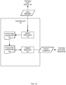
- FIG. 1A shows a more detailed block diagram of the controller 112 that is configured to predict future data requests based on time series modeling.
- the controller 112 may implement a time series modeler that comprises four main components: (1) an event recorder 118; (2) a detection algorithm 120; (3) a predictor algorithm 122; and (4) a power manager 124. These components will now be further described.
- the event recorder 118 records information about the data requests received from the client 104.
- the event recorder 118 may record various aspects of the data requests, such as date/time of the request, file type, file size, etc.
- the event recorder 118 may be implemented in the controller 112 in a wide variety of ways.
- the event recorder 118 may be firmware within the controller 112 that is configured to perform the functions of recording data requests.
- the event recorder 118 may be software running in the controller 112 that continually records the behavior of the user of the device over time.
- the event recorder 118 records some or all of the data requests from the clients 104 and every data point (or a selection of data points) essentially serves as a training point and the collection of data points continually adds to the accuracy of the overall prediction.
- the controller 112 executes the detection algorithm 120 to recognize various patterns within the previously data collected by the event recorder 118.
- the detection algorithm 120 determines the various inter-arrival intervals of the data requests to generate a set of time series of intervals. The detection algorithm 120 may then identify or detect user behavior based on the patterns existing in these time series of intervals.
- the controller 112 may also execute a predictor algorithm 122. Once a pattern has emerged, the predictor algorithm 122 provides the logic for predicting the future behavior of the user and when one or more future data requests from client 104 is expected. The predictor algorithm 122 may output its predictions in various formats, such as a time offset, a confidence factor, etc.
- the controller 112 may comprise a power manager 124.
- the power manager 124 manages the power state and power consumption of the NAS 102, such as the storage interface 114 and disks 116.
- the controller 112 is configured to use the power manager 124 to anticipate user data request usage based on the predictions of the predictor algorithm 122. For example, in response to a predicted future data request by the predictor algorithm 122, the controller 112 may signal the power manager 124 to transition the power state of the disks 116 to commence spinning the hard disks 116 at the predicted time of the next data request.
- the controller 112 may signal the power manager 124 to power down or reduce the power consumption of the disks 116 and/or the storage interface 114 when a long idle period or time until the next data request is predicted.
- Various thresholds for when the controller 112 and the power manager 124 change the power state and operation may vary, for example, based on spin up times, communications latency, read/write latency, etc.
- the controller 112 and the power manager 124 may modify its power management schemes based on various criteria, such as battery charge state, frequency of data requests, and the like.
- FIG. 2 For the purpose of illustration, a simple example of a user behavior and series of data requests is shown with reference to FIG. 2 .
- FIG. 2 Example User Behavior (Simplified)
- the graph can represent the behavior of a user at client 104 that has accessed data on the device in 100 hour intervals since he has turned on the NAS 102 initially.
- the controller 112 can thus make a simple prediction can from such user behavior.
- FIG. 3 Prediction of User Behavior
- FIG. 3 illustrates a predicted data request event determined by the controller 112.
- various "User-Data-Request” points (to indicate data requests from the client 104) are marked as R n and a "Future Event Prediction” point predicted by the controller 112 is marked as P n where n is 1,2,3, and so forth.
- P n the time interval between R 2 and R 1 may be represented as ⁇ 1 and R 3 and R 2 may be represented as ⁇ 2 .
- the predictor algorithm 122 can predict a pattern and hence a future data request. That is, the next user request can be predicted ⁇ 1 or ⁇ 2 away from R 3 (i.e. about 100 hours).
- the prediction algorithm 122 may include an error buffer.
- the algorithm may formulated and simplified below:
- the detection algorithm 120 is configured to express the deltas in matrix form as suggested below: ⁇ 1,1 ⁇ ⁇ 1, j ⁇ ⁇ ⁇ ⁇ i ,1 ⁇ ⁇ i , j where ⁇ i,j refers to the time interval between R i and R j .
- the controller 112 may construct the following simplified matrix below: 0 2 5 14 16 19 28 30 33 43 53 63 0 0 3 12 14 17 26 28 31 41 51 61 0 0 0 9 11 14 23 25 28 38 48 58 0 0 0 0 2 5 14 16 19 29 39 49 0 0 0 0 3 12 14 17 27 37 47 0 0 0 0 0 9 11 14 24 34 44 0 0 0 0 0 0 0 2 5 15 25 35 0 0 0 0 0 0 0 0 3 13 23 33 0 0 0 0 0 0 0 0 10 20 30 0 0 0 0 0 0 0 0 0 10 20 0 0 0 0 0 0 0 0 0 0 0 0 10 0 0 0 0 0 0 0 0 0 0 10 20 0 0 0 0 0 0 0 0 0 0 0 10
Landscapes
- Engineering & Computer Science (AREA)
- Theoretical Computer Science (AREA)
- General Engineering & Computer Science (AREA)
- Physics & Mathematics (AREA)
- Quality & Reliability (AREA)
- General Physics & Mathematics (AREA)
- Computer Hardware Design (AREA)
- Life Sciences & Earth Sciences (AREA)
- Bioinformatics & Cheminformatics (AREA)
- Bioinformatics & Computational Biology (AREA)
- Evolutionary Biology (AREA)
- Probability & Statistics with Applications (AREA)
- Debugging And Monitoring (AREA)
- Power Sources (AREA)
Description
- The responsiveness of a computing device is an important characteristic of its performance. Ideally, a computing device is able to respond to a user as quickly as possible.
- For example, storage devices attempt to provide access to their stored data as efficiently and as quickly as possible. Today, solid-state drives (SSDs) have become popular due to their near-zero data access-time delay (DATD) performance relative to hard disk drives (HDDs). HDDs, however, still offer higher capacity storage at a lower cost relative to SSDs. Accordingly, HDDs remain popular due to their high capacity and durability. Indeed, many known products, such as solid state hybrid drives (SSHD) now provide a combination of SSD and HDD as a storage solution.
- HDDs normally have a high DATD because they are frequently put into a standby mode in order to conserve power, etc. For example, mobile devices, such as a laptop, wireless Network Attached Storage (NAS), or any other mobile device, frequently employ aggressive HDD standby policies. HDDs may also be put into a standby mode for data safety reasons during various movements the head would not make contact with the disk.
- Unfortunately, when exiting standby mode in response to a data access request, an HDD may take a long time for the drive to spin back up. Moreover, as the hard drive capacities increase, the DATD may also increase when coming out of standby mode.
- Therefore, it would be desirable to provide methods and systems that can minimize the DATD of a HDD. It would also be desirable to provide methods and systems that can improve the responsiveness of any computing device, especially after idle periods of time.
-
EP 1 918 809 - According to the invention, there is provided a method of predicting future access of a storage device as set out in
claim 1, and a storage device configured to anticipate user behaviour as set out in claim 8. - Systems and methods which embody the various features of the invention will now be described with reference to the following drawings, in which:
-
FIG. 1 illustrates an exemplary system in which embodiments of the present invention may be implemented; -
FIG. 1A illustrates an exemplary controller that is configured to predict user data requests in accordance with embodiments of the present invention; -
FIG. 2 illustrates an exemplary user behavioral pattern; -
FIG. 3 illustrates an exemplary predicted access event based on time series modeling by some embodiments of the present invention; -
FIG. 4 illustrates exemplary time series modeling used by some embodiments to predict various data access events; -
FIG. 5 illustrates an exemplary graph of data access events predicted by the some embodiments and actual user data requests; and -
FIG. 6 illustrates an exemplary process flow. - Embodiments of the present invention improve the data access time delay for accessing stored data based on predicting when data access requests may occur. In some embodiments, the storage device observes user behavior and uses time series modeling to predict or anticipate when a user is likely to access a storage system. Some embodiments are implemented on storage devices containing one or more hard disk drives alone or in combination with other types of storage devices. The embodiments may employ software, firmware, etc. to implement the predictive algorithms used to anticipate when data access requests may occur.
- For the purpose of illustration, an example will now be described with reference to a network-attached storage that comprises one or more hard disk drives. Those skilled in the art will recognize that the embodiments may be implemented on a wide variety of types of storage types, such as direct-attached storage, storage area networks, and the like.
- Certain embodiments will now be described. These embodiments are presented by way of example only, and are not intended to limit the scope of the invention. Indeed, the novel methods and systems described herein may be embodied in a variety of other forms. To illustrate some of the embodiments, reference will now be made to the figures.
-
FIG. 1 illustrates an exemplary system.FIG. 1A illustrates an exemplary controller that is configured to predict user data requests in accordance with embodiments of the present invention.FIG. 2 illustrates an exemplary user behavioral pattern, which may be analyzed and predicted by the embodiments.FIG. 3 illustrates an exemplary predicted access event based on time series modeling by some embodiments of the present invention.FIG. 4 illustrates exemplary time series modeling used by some embodiments to predict various data access events.FIG. 5 illustrates an exemplary graph of data access events predicted by some embodiments and actual user data requests.FIG. 6 illustrates an exemplary process flow.FIGs. 1 -5 will now be further described below. -
FIG. 1 shows an exemplary system of an embodiment of the present invention. The embodiments of the present invention may be implemented on any type of storage device or device that provides file notification services. For purposes of illustration, anexemplary system 100 is shown with a network-attached storage (NAS) 102 that services a client (or host device) 104 via anetwork 106. Thesystem 100 may also be used in other devices in which predictive capabilities are desired, such as mobile devices, media streaming/playback devices, laptops, tablets, desktop computers, smart televisions, or other types of electronic devices. An exemplary embodiment with these components will now be briefly described below. - The NAS 102 is file-level storage device that is capable of connecting to a network, such as
network 106 and provides access to files stored in its storage medium as a file server. In one embodiment, NAS 102 is implemented with known hardware, software, and firmware. For example, in one embodiment, the NAS 102 is configured as an appliance having an embedded operating system. The NAS 102 may support a variety of operating systems, such as UNIX, LINUX, Windows, and the like. As will be further described, the NAS 102 may also comprise multiple storage mediums, such as one or more hard disks that are arranged into a redundant array of independent disks (RAID). Furthermore, the NAS 102 may support various protocols, such as NFS, SMB/CIFS, AFP, etc. - As shown, the NAS 102 may comprise a
network interface 110, acontroller 112, astorage interface 114, and a storage array ofdisks 116. These components will now be briefly described below. -
Network interface 110 serves as the network communications interface for the NAS 102 to/fromnetwork 106. For example, in one embodiment, thenetwork interface 200 may comprise one or more Gigabit Ethernet, Ethernet, Universal Serial Bus (USB), or other interfaces for communications withnetwork 106. Such components are known to those skilled in the art. -
Controller 112 represents the hardware and software that manages thedisks 116 of theNAS 102 and presents them as a logical unit or volume to theclients 104. In some embodiments, thecontroller 112 may also comprise one or more other components to supplement its operations, such as an on-chip RAID controller, a memory or disk cache, etc. Furthermore, in the embodiments, thecontroller 112 is configured to observe user behavior with regard to data requests fromclient 104, detect patterns in that behavior, and predict various future data requests. Thecontroller 112 may then manage or manipulate the operations and power state of thevarious disks 116 via thestorage interface 114. In some embodiments, thecontroller 112 employs a time series modeling to predict future data requests and manages thedisks 116 accordingly to improve their data access time and/or minimize their DATD. An example of the time series modeling algorithms and implementations is described further below. -
Storage interface 114 serves as an interface between thecontroller 112 and the disks 206. Thestorage interface 114 may support various communications, such as SAS, SATA, SCSI, etc. -
Disks 116 represent the storage medium and associated electronics for the devices storing data for theNAS 102. In one embodiment, thedisks 116 may be implemented as hard disk drives, such as those provided by Western Digital Technologies, Inc. Of course, in other embodiments, theNAS 102 may comprise other types of storage media and devices, such as solid-state drives, hybrid drives, etc. Any type of storage drive that can be configured as part of a RAID may be implemented as part of an embodiment of the present invention. - Alternatively, as noted above, in other embodiments, the
system 100 may comprise direct attached storage devices or external drives. For example, thesystem 100 may comprise one or more external drives, such as the MyBook or Passport devices provided by Western Digital Technologies, Inc. -
Clients 104 represent the various client devices that may store and/or access files on theNAS 102. For example, theclients 104 may be a desktop, a laptop, a tablet, a smart phone, etc. The embodiments support any device that can access a file stored on theNAS 102. -
Network 106 provides a communication infrastructure for data communications between the components ofsystem 100.Network 106 may comprise known network elements, such as hubs, switches, routers, firewalls, etc., to facilitate and secure these communications. In the embodiments, thenetwork 106 may comprise a local area network, a wide area network, etc. In addition, thenetwork 106 may comprise wired and wireless links or components to carry its communications. - Further to
FIG. 1 ,FIG. 1A shows a more detailed block diagram of thecontroller 112 that is configured to predict future data requests based on time series modeling. In some embodiments, thecontroller 112 may implement a time series modeler that comprises four main components: (1) anevent recorder 118; (2) adetection algorithm 120; (3) apredictor algorithm 122; and (4) apower manager 124. These components will now be further described. - The
event recorder 118 records information about the data requests received from theclient 104. Theevent recorder 118 may record various aspects of the data requests, such as date/time of the request, file type, file size, etc. Theevent recorder 118 may be implemented in thecontroller 112 in a wide variety of ways. For example, theevent recorder 118 may be firmware within thecontroller 112 that is configured to perform the functions of recording data requests. As another example, theevent recorder 118 may be software running in thecontroller 112 that continually records the behavior of the user of the device over time. In some embodiments, theevent recorder 118 records some or all of the data requests from theclients 104 and every data point (or a selection of data points) essentially serves as a training point and the collection of data points continually adds to the accuracy of the overall prediction. - The
controller 112 executes thedetection algorithm 120 to recognize various patterns within the previously data collected by theevent recorder 118. In some embodiments, thedetection algorithm 120 determines the various inter-arrival intervals of the data requests to generate a set of time series of intervals. Thedetection algorithm 120 may then identify or detect user behavior based on the patterns existing in these time series of intervals. - The
controller 112 may also execute apredictor algorithm 122. Once a pattern has emerged, thepredictor algorithm 122 provides the logic for predicting the future behavior of the user and when one or more future data requests fromclient 104 is expected. Thepredictor algorithm 122 may output its predictions in various formats, such as a time offset, a confidence factor, etc. - Finally, the
controller 112 may comprise apower manager 124. Thepower manager 124 manages the power state and power consumption of theNAS 102, such as thestorage interface 114 anddisks 116. In some embodiments, thecontroller 112 is configured to use thepower manager 124 to anticipate user data request usage based on the predictions of thepredictor algorithm 122. For example, in response to a predicted future data request by thepredictor algorithm 122, thecontroller 112 may signal thepower manager 124 to transition the power state of thedisks 116 to commence spinning thehard disks 116 at the predicted time of the next data request. In addition, thecontroller 112 may signal thepower manager 124 to power down or reduce the power consumption of thedisks 116 and/or thestorage interface 114 when a long idle period or time until the next data request is predicted. Various thresholds for when thecontroller 112 and thepower manager 124 change the power state and operation may vary, for example, based on spin up times, communications latency, read/write latency, etc. Furthermore, thecontroller 112 and thepower manager 124 may modify its power management schemes based on various criteria, such as battery charge state, frequency of data requests, and the like. - To illustrate the concepts of the invention, the detection and prediction algorithms will now be described further below with reference to
FIGs 2-5 . For the purpose of illustration, a simple example of a user behavior and series of data requests is shown with reference toFIG. 2 . - As shown in
FIG. 2 , the graph can represent the behavior of a user atclient 104 that has accessed data on the device in 100 hour intervals since he has turned on theNAS 102 initially. In this example, thecontroller 112 can thus make a simple prediction can from such user behavior. - For example,
FIG. 3 illustrates a predicted data request event determined by thecontroller 112. As shown, various "User-Data-Request" points (to indicate data requests from the client 104) are marked as Rn and a "Future Event Prediction" point predicted by thecontroller 112 is marked as Pn where n is 1,2,3, and so forth. As can be seen, the time interval between R2 and R1 may be represented as Δ1 and R3 and R2 may be represented as Δ2. - In one embodiment, if Δ1 and Δ2 are found to be equal or within a certain tolerance, the
predictor algorithm 122 can predict a pattern and hence a future data request. That is, the next user request can be predicted Δ1 or Δ2 away from R3 (i.e. about 100 hours). - In some embodiments, in order to account for some fluctuations in user request behavior, the
prediction algorithm 122 may include an error buffer. For example, the algorithm may formulated and simplified below: - if |Δ n+1 - Δ n | ≤ εr ⇒ Δ' n+2 = min(Δ n ,Δ n+1) - εr - ts, where min is the minimum function,
- εr is the buffer accounting for fluctuations in user request, and
- ts is the DATD, such as the time it takes for the drive to spin up and device to get ready to response to user's request), and finally
- Δ' n+2 is the future prediction interval (shown in
FIG. 3 as the interval between R3 and P1). - In one embodiment, for the ease of computation, the
detection algorithm 120 is configured to express the deltas in matrix form as suggested below:
- As can be seen, the matrix is a square matrix with all the elements on its main diagonal equaling 0. In addition, the lower triangular part of the matrix contains the same data as the upper triangular part of the matrix so that lower triangular part can be neglected (for example to conserve memory) and based on these the simplification of the above matrix the following matrix results:

- Accordingly, any row i contains all deltas pertaining to a data request point Rj to all other future data request points. Also any column j contains all deltas pertaining to intervals from all other past data request point to Rj. In order to visualize this example,
FIG. 4 shows the graph illustrating the intervals expressed in the matrix. - In some embodiments, the
controller 112 is configured to perform time series modeling to identify patterns within the matrix, based on theprediction algorithm 122. An example of thedetection algorithm 120 and time series modeling will now be provided in reference to the following hypothetical user pattern.User Data Request points R1 R2 R3 R4 R5 R6 R7 R8 R9 R10 R11 R12 Unit of Time (hrs) 5 7 10 19 21 24 33 35 38 48 58 68 - From this dataset, the
controller 112 may construct the following simplified matrix below:0 2 5 14 16 19 28 30 33 43 53 63 0 0 3 12 14 17 26 28 31 41 51 61 0 0 0 9 11 14 23 25 28 38 48 58 0 0 0 0 2 5 14 16 19 29 39 49 0 0 0 0 0 3 12 14 17 27 37 47 0 0 0 0 0 0 9 11 14 24 34 44 0 0 0 0 0 0 0 2 5 15 25 35 0 0 0 0 0 0 0 0 3 13 23 33 0 0 0 0 0 0 0 0 0 10 20 30 0 0 0 0 0 0 0 0 0 0 10 20 0 0 0 0 0 0 0 0 0 0 0 10 - In one embodiment, the
detection algorithm 120 may be implemented based on the following pseudo-code to identify patterns in the user access request.
           clc
           G=[];
           l=[5 7 10 19 21 24 33 35 38 48 58 68]; % vector of intervals starting at l=1
           l_size=size(l');
           for i=1:l_size;
           for j=1:l_size
           Delta(i,j)=abs(l(i)-l(j));
           end
           end
           Delta=triu(Delta)
           for i=1:l_size
           col_v=Delta(:,i);
           row_v=Delta(i,:);
           t_col=col_v(col_v∼=0);
           t_row=row_v(row_v∼=0);
           RESULT=ismember(col_v,crow);
           [row_i,col_i]=find(RESULT == 1);
           if isempty(Delta(row_i,i))
             % disp'this is empty'
             % Delta(row_i,j)
           else
           detected_delta=Delta(row_i,i)
           G(end+1)=l(i)+detected_delta;
           end
           end
           figure
           plot(l,1,'bx' G, 1,'ro');
           legend('User Data Request','Future Event Prediction');

Claims (14)
- A method of predicting future access of a storage device, said method comprising:recording a time series of access requests for data from the storage device;determining (600) respective time intervals between each access request to any subsequent access request of the storage device;arranging the respective time intervals in a matrix, wherein each column of the matrix indicates time intervals from all other past access requests and wherein each row indicates time intervals to subsequent access requests;identifying (602) a pattern in the respective time intervals, including determining a first set of intervals occurring in a column of the matrix that matches a second set of intervals occurring in a row of the matrix;predicting a next access request based on the pattern in the respective time intervals; andproactively activating the storage device based on the predicted next access request.
- The method of claim 1, wherein proactively activating the storage device comprises proactively spinning up a hard disk drive before the predicted next access request based on a spin up time of the hard disk drive.
- The method of claim 1, wherein proactively activating the storage device comprises proactively activating the storage device before the predicted next access request based on the respective intervals and a tolerance.
- The method of claim 1, further comprising determining an error tolerance between the respective intervals and grouping a plurality of access requests that occur within the error tolerance.
- The method of claim 1 adapted for managing an electronic device based on predicting user behaviour, wherein said method comprises:recording a series of user access requests of the electronic device over a period of time, wherein said respective time intervals are determined between the series of user access requests, and wherein each column of the matrix indicates time intervals from all other past user access requests and wherein each row indicates time intervals to subsequent user access requests;determining a predicted time of a next user access request based on the identified pattern; andinitiating (604) an action on the electronic device based on the predicted time of the next user access request.
- The method of claim 5, wherein identifying the pattern comprises identifying a sequence of intervals that occur in both a row and a column from a selected element in the matrix within a tolerance.
- The method of claim 5, wherein initiating the action on the electronic device comprises initiating spin up of a hard disk drive or initiating a spin down of a hard disk drive.
- A storage device configured to anticipate user behaviour based on modelling a time series of user access requests, said storage device comprising:at least one storage medium (116); anda controller (112) comprising:an event recorder (118) configured to record a time series of user access requests for data from the at least one storage medium and to store the time series in a matrix, wherein each column of the matrix indicates time intervals from all other past user access requests and wherein each row indicates time intervals to subsequent user access requests;a power manager (124) configured to manage power consumption of the at least one storage medium based on an active state and a standby state;a time series modeller (120) configured to detect patterns of user behaviour based on intervals in the time series between user access requests, wherein the time series modeller is configured to detect patterns of user behaviour based on matching sequences of intervals occurring in both a row and a column of the matrix; anda predictor (122) configured to predict a next user access request based on the patterns of user behaviour and send a signal to the power manager to transition the storage device from a first power state to a second power state in anticipation of the predicted next user access request.
- The storage device of claim 8, wherein the predictor is configured to send a signal to transition the at least one storage medium from 1) a standby state to an active state or 2) an active state to a standby state in anticipation of the predicted next user access request.
- The storage device of claim 8, wherein the controller comprises
a processor configured by executable program code to perform the method of claim 5. - The storage device of claim 10, wherein the storage medium comprises a hard disk drive and the processor is configured to initiate spin up or spin down of the hard disk drive.
- The storage device of claim 10, wherein the storage medium comprises a hard disk drive and the processor is configured to transition the hard disk drive from a standby state to an active state or from an active state to a standby state.
- The storage device of claim 10, wherein the processor is configured to initiate caching content responsive to the pattern of user access.
- The storage device of claim 10, wherein the processor is configured to connect to a network responsive to the pattern of user access.
Applications Claiming Priority (3)
| Application Number | Priority Date | Filing Date | Title |
|---|---|---|---|
| US201361807665P | 2013-04-02 | 2013-04-02 | |
| US14/063,982 US9152490B2 (en) | 2013-04-02 | 2013-10-25 | Detection of user behavior using time series modeling |
| PCT/US2014/032424 WO2014165456A1 (en) | 2013-04-02 | 2014-03-31 | Detection of user behavior using time series modeling |
Publications (3)
| Publication Number | Publication Date |
|---|---|
| EP2981920A1 EP2981920A1 (en) | 2016-02-10 |
| EP2981920A4 EP2981920A4 (en) | 2017-01-04 |
| EP2981920B1 true EP2981920B1 (en) | 2018-08-01 |
Family
ID=51622075
Family Applications (1)
| Application Number | Title | Priority Date | Filing Date |
|---|---|---|---|
| EP14779416.8A Active EP2981920B1 (en) | 2013-04-02 | 2014-03-31 | Detection of user behavior using time series modeling |
Country Status (5)
| Country | Link |
|---|---|
| US (1) | US9152490B2 (en) |
| EP (1) | EP2981920B1 (en) |
| CN (1) | CN105247492B (en) |
| HK (1) | HK1216199A1 (en) |
| WO (1) | WO2014165456A1 (en) |
Families Citing this family (8)
| Publication number | Priority date | Publication date | Assignee | Title |
|---|---|---|---|---|
| US9442668B1 (en) * | 2013-08-29 | 2016-09-13 | Western Digital Technologies, Inc. | Adaptive power management control with performance feedback |
| JP2015203980A (en) * | 2014-04-14 | 2015-11-16 | キヤノン株式会社 | Information processing device and control method of the same, and program |
| US9921637B2 (en) * | 2015-10-26 | 2018-03-20 | Nxp Usa, Inc. | Multi-port power prediction for power management of data storage devices |
| CN106844047B (en) * | 2017-01-11 | 2021-06-04 | 上海传英信息技术有限公司 | Application program optimization method of intelligent terminal |
| US10514745B2 (en) * | 2017-09-29 | 2019-12-24 | Intel Corporation | Techniques to predict memory bandwidth demand for a memory device |
| KR102481794B1 (en) * | 2018-04-18 | 2022-12-28 | 한국전자통신연구원 | Method and Apparatus of danger detection based on time series analysis of human activities |
| CN110796007B (en) * | 2019-09-27 | 2023-03-03 | 华为技术有限公司 | Scene recognition method and computing device |
| CN111813640B (en) * | 2020-03-25 | 2024-09-24 | 北京嘀嘀无限科技发展有限公司 | Method, apparatus, electronic device and storage medium for predicting user behavior |
Family Cites Families (54)
| Publication number | Priority date | Publication date | Assignee | Title |
|---|---|---|---|---|
| US5481733A (en) * | 1994-06-15 | 1996-01-02 | Panasonic Technologies, Inc. | Method for managing the power distributed to a disk drive in a laptop computer |
| AU2056401A (en) | 1999-12-02 | 2001-06-12 | Senvid, Inc. | Method, system and service model for remote recording of television programs |
| US6499054B1 (en) | 1999-12-02 | 2002-12-24 | Senvid, Inc. | Control and observation of physical devices, equipment and processes by multiple users over computer networks |
| US7917628B2 (en) | 1999-12-02 | 2011-03-29 | Western Digital Technologies, Inc. | Managed peer-to-peer applications, systems and methods for distributed data access and storage |
| US7120692B2 (en) | 1999-12-02 | 2006-10-10 | Senvid, Inc. | Access and control system for network-enabled devices |
| US7934251B2 (en) | 1999-12-02 | 2011-04-26 | Western Digital Technologies, Inc. | Managed peer-to-peer applications, systems and methods for distributed data access and storage |
| US8793374B2 (en) | 1999-12-02 | 2014-07-29 | Western Digital Technologies, Inc. | Managed peer-to-peer applications, systems and methods for distributed data access and storage |
| US8688797B2 (en) | 1999-12-02 | 2014-04-01 | Western Digital Technologies, Inc. | Managed peer-to-peer applications, systems and methods for distributed data access and storage |
| US7587467B2 (en) | 1999-12-02 | 2009-09-08 | Western Digital Technologies, Inc. | Managed peer-to-peer applications, systems and methods for distributed data access and storage |
| US9191443B2 (en) | 1999-12-02 | 2015-11-17 | Western Digital Technologies, Inc. | Managed peer-to-peer applications, systems and methods for distributed data access and storage |
| US7949564B1 (en) | 2000-05-31 | 2011-05-24 | Western Digital Technologies, Inc. | System and method of receiving advertisement content from advertisers and distributing the advertising content to a network of personal computers |
| EP1197855A3 (en) * | 2000-07-27 | 2007-12-12 | Matsushita Electric Industrial Co., Ltd. | Data processing control system |
| US6892313B1 (en) | 2001-06-21 | 2005-05-10 | Western Digital Technologies, Inc. | Method for predictive power management for operating a disk drive in a mobile device to optimize power usage |
| US20020199129A1 (en) * | 2001-06-21 | 2002-12-26 | International Business Machines Corp. | Data storage on a computer disk array |
| US7120806B1 (en) | 2001-10-31 | 2006-10-10 | Western Digital Technologies, Inc. | Method for setting a power operating mode transition interval of a disk drive in a mobile device based on application category |
| US6757622B2 (en) * | 2002-01-17 | 2004-06-29 | Seagate Technology Llc | Predicting disc drive acoustic sound power from mechanical vibration |
| JP2003309797A (en) | 2002-04-17 | 2003-10-31 | Sharp Corp | Hard disk video camera provided with low power consumption mode |
| US7454443B2 (en) | 2003-08-26 | 2008-11-18 | Tamir Ram | Method, system, and program for personal data management using content-based replication |
| EP1751745B1 (en) | 2003-11-14 | 2019-07-10 | Western Digital Technologies, Inc. | Managed peer-to-peer applications, systems and methods for distributed data access and storage |
| JP2005149436A (en) * | 2003-11-20 | 2005-06-09 | Hitachi Ltd | Storage apparatus, control method for storage apparatus, job scheduling processing method, troubleshooting method and their program |
| US7334082B2 (en) | 2003-12-30 | 2008-02-19 | Intel Corporation | Method and system to change a power state of a hard drive |
| US7428622B2 (en) * | 2004-09-28 | 2008-09-23 | Akhil Tulyani | Managing disk storage media based on access patterns |
| US7516346B2 (en) | 2004-10-28 | 2009-04-07 | Nec Laboratories America, Inc. | System and method for dynamically changing the power mode of storage disks based on redundancy and system load |
| JP2007179089A (en) | 2005-12-26 | 2007-07-12 | Toshiba Corp | Information processor, access control method and program |
| JP4749255B2 (en) * | 2006-07-03 | 2011-08-17 | 株式会社日立製作所 | Storage system control device having multiple types of storage devices |
| US7411757B2 (en) | 2006-07-27 | 2008-08-12 | Hitachi Global Storage Technologies Netherlands B.V. | Disk drive with nonvolatile memory having multiple modes of operation |
| US7716425B1 (en) * | 2006-09-27 | 2010-05-11 | Hewlett-Packard Development Company, L.P. | Prefetching data in distributed storage systems |
| JP2008112292A (en) * | 2006-10-30 | 2008-05-15 | Hitachi Ltd | Storage system and power supply control method for storage system |
| US8004791B2 (en) | 2008-02-22 | 2011-08-23 | Western Digital Technologies, Inc. | Information storage device with a bridge controller and a plurality of electrically coupled conductive shields |
| CN101520689B (en) * | 2009-04-17 | 2012-10-03 | 成都市华为赛门铁克科技有限公司 | Computer memory device control method, computer memory device controller and memory device |
| JP5250482B2 (en) * | 2009-05-21 | 2013-07-31 | 株式会社日立製作所 | Power saving control apparatus and method |
| WO2011007391A1 (en) * | 2009-07-15 | 2011-01-20 | Hitachi, Ltd. | Storage system, control method of storage device |
| US8255661B2 (en) | 2009-11-13 | 2012-08-28 | Western Digital Technologies, Inc. | Data storage system comprising a mapping bridge for aligning host block size with physical block size of a data storage device |
| US8285965B2 (en) | 2009-11-20 | 2012-10-09 | Western Digital Technologies, Inc. | Aligning data storage device partition to boundary of physical data sector |
| US8526798B2 (en) | 2009-12-23 | 2013-09-03 | Western Digital Technologies, Inc. | Portable content container displaying A/V files in response to a command received from a consumer device |
| KR20110097438A (en) * | 2010-02-25 | 2011-08-31 | 삼성전자주식회사 | Memory system and operation method thereof |
| US8631284B2 (en) | 2010-04-30 | 2014-01-14 | Western Digital Technologies, Inc. | Method for providing asynchronous event notification in systems |
| US8762682B1 (en) | 2010-07-02 | 2014-06-24 | Western Digital Technologies, Inc. | Data storage apparatus providing host full duplex operations using half duplex storage devices |
| US10019741B2 (en) | 2010-08-09 | 2018-07-10 | Western Digital Technologies, Inc. | Methods and systems for a personal multimedia content archive |
| US8713265B1 (en) | 2010-09-21 | 2014-04-29 | Western Digital Technologies, Inc. | Visual indicator of online backup |
| US8661067B2 (en) * | 2010-10-13 | 2014-02-25 | International Business Machines Corporation | Predictive migrate and recall |
| US20120314358A1 (en) * | 2011-06-07 | 2012-12-13 | Shao-Chieh Ting | Keyboard device capable of supporting a tablet personal computer |
| US8836536B2 (en) | 2011-07-29 | 2014-09-16 | Hewlett-Packard Development Company, L. P. | Device characterization system and methods |
| JP5773493B2 (en) * | 2011-11-14 | 2015-09-02 | インターナショナル・ビジネス・マシーンズ・コーポレーションInternational Business Machines Corporation | Information processing device |
| JP5895944B2 (en) * | 2011-12-21 | 2016-03-30 | 富士通株式会社 | Management device, management program, and management method |
| US8780004B1 (en) | 2012-01-31 | 2014-07-15 | Western Digital Technologies, Inc. | Dual configuration enclosure with optional shielding |
| US8819443B2 (en) | 2012-02-14 | 2014-08-26 | Western Digital Technologies, Inc. | Methods and devices for authentication and data encryption |
| US8646054B1 (en) | 2012-03-23 | 2014-02-04 | Western Digital Technologies, Inc. | Mechanism to manage access to user data area with bridged direct-attached storage devices |
| US8914634B2 (en) | 2012-04-10 | 2014-12-16 | Western Digital Technologies, Inc. | Digital rights management system transfer of content and distribution |
| US8831217B2 (en) | 2012-04-10 | 2014-09-09 | Western Digital Technologies, Inc. | Digital rights management system and methods for accessing content from an intelligent storage |
| US9626373B2 (en) | 2012-10-01 | 2017-04-18 | Western Digital Technologies, Inc. | Optimizing data block size for deduplication |
| US9280482B2 (en) | 2012-12-13 | 2016-03-08 | Western Digital Technologies, Inc. | Methods and systems for provisioning a bootable image on to an external drive |
| US20140169921A1 (en) | 2012-12-19 | 2014-06-19 | Mark Carey | Cargo carrier |
| CN104956322B (en) * | 2013-03-05 | 2019-03-01 | 英特尔公司 | Analyze the potential benefit of vectorization |
-
2013
- 2013-10-25 US US14/063,982 patent/US9152490B2/en not_active Expired - Fee Related
-
2014
- 2014-03-31 EP EP14779416.8A patent/EP2981920B1/en active Active
- 2014-03-31 CN CN201480020276.4A patent/CN105247492B/en active Active
- 2014-03-31 WO PCT/US2014/032424 patent/WO2014165456A1/en active Application Filing
-
2016
- 2016-04-13 HK HK16104180.4A patent/HK1216199A1/en unknown
Non-Patent Citations (1)
| Title |
|---|
| None * |
Also Published As
| Publication number | Publication date |
|---|---|
| EP2981920A1 (en) | 2016-02-10 |
| US20140298117A1 (en) | 2014-10-02 |
| CN105247492B (en) | 2018-12-21 |
| US9152490B2 (en) | 2015-10-06 |
| WO2014165456A1 (en) | 2014-10-09 |
| EP2981920A4 (en) | 2017-01-04 |
| CN105247492A (en) | 2016-01-13 |
| HK1216199A1 (en) | 2016-10-21 |
Similar Documents
| Publication | Publication Date | Title |
|---|---|---|
| EP2981920B1 (en) | Detection of user behavior using time series modeling | |
| US11422722B2 (en) | Intelligent wide port PHY usage | |
| US8880835B2 (en) | Adjusting location of tiered storage residence based on usage patterns | |
| US8190832B2 (en) | Data storage performance enhancement through a write activity level metric recorded in high performance block storage metadata | |
| EP2976713B1 (en) | Information processing system, control program, and information processing device | |
| US9454321B1 (en) | Workload-driven storage configuration management | |
| US8521986B2 (en) | Allocating storage memory based on future file size or use estimates | |
| US20130290598A1 (en) | Reducing Power Consumption by Migration of Data within a Tiered Storage System | |
| EP4030273A1 (en) | Data storage method and device | |
| US8560801B1 (en) | Tiering aware data defragmentation | |
| US9182912B2 (en) | Method to allow storage cache acceleration when the slow tier is on independent controller | |
| US9110599B1 (en) | Thin provisioning of VTL tape pools with MTree logical quotas | |
| US10225158B1 (en) | Policy based system management | |
| US20180181307A1 (en) | Information processing device, control device and method | |
| US8924642B2 (en) | Monitoring record management method and device | |
| WO2023020136A1 (en) | Data storage method and apparatus in storage system | |
| US12019532B2 (en) | Distributed file system performance optimization for path-level settings using machine learning | |
| US9063842B1 (en) | Technique for integrating VTL tape pools with MTree quotas | |
| US9135191B1 (en) | Techniques for storage network bandwidth management | |
| US10474363B1 (en) | Space reporting in a storage system | |
| TW201443647A (en) | Tiered data storage system with data management and method of operation thereof | |
| US10320907B2 (en) | Multi-stage prefetching to exploit long-term future data access sequence knowledge | |
| US20230305728A1 (en) | Management system, storage system, and management processing method | |
| WO2023279833A1 (en) | Data processing method and apparatus | |
| US20150039659A1 (en) | Data location management agent using remote storage |
Legal Events
| Date | Code | Title | Description |
|---|---|---|---|
| PUAI | Public reference made under article 153(3) epc to a published international application that has entered the european phase |
Free format text: ORIGINAL CODE: 0009012 |
|
| 17P | Request for examination filed |
Effective date: 20150925 |
|
| AK | Designated contracting states |
Kind code of ref document: A1 Designated state(s): AL AT BE BG CH CY CZ DE DK EE ES FI FR GB GR HR HU IE IS IT LI LT LU LV MC MK MT NL NO PL PT RO RS SE SI SK SM TR |
|
| AX | Request for extension of the european patent |
Extension state: BA ME |
|
| DAX | Request for extension of the european patent (deleted) | ||
| REG | Reference to a national code |
Ref country code: DE Ref legal event code: R079 Ref document number: 602014029591 Country of ref document: DE Free format text: PREVIOUS MAIN CLASS: G06F0019000000 Ipc: G06F0011340000 |
|
| A4 | Supplementary search report drawn up and despatched |
Effective date: 20161202 |
|
| RIC1 | Information provided on ipc code assigned before grant |
Ipc: G06F 11/34 20060101AFI20161128BHEP |
|
| STAA | Information on the status of an ep patent application or granted ep patent |
Free format text: STATUS: EXAMINATION IS IN PROGRESS |
|
| 17Q | First examination report despatched |
Effective date: 20171017 |
|
| GRAP | Despatch of communication of intention to grant a patent |
Free format text: ORIGINAL CODE: EPIDOSNIGR1 |
|
| STAA | Information on the status of an ep patent application or granted ep patent |
Free format text: STATUS: GRANT OF PATENT IS INTENDED |
|
| INTG | Intention to grant announced |
Effective date: 20180207 |
|
| GRAS | Grant fee paid |
Free format text: ORIGINAL CODE: EPIDOSNIGR3 |
|
| GRAJ | Information related to disapproval of communication of intention to grant by the applicant or resumption of examination proceedings by the epo deleted |
Free format text: ORIGINAL CODE: EPIDOSDIGR1 |
|
| GRAL | Information related to payment of fee for publishing/printing deleted |
Free format text: ORIGINAL CODE: EPIDOSDIGR3 |
|
| STAA | Information on the status of an ep patent application or granted ep patent |
Free format text: STATUS: EXAMINATION IS IN PROGRESS |
|
| GRAR | Information related to intention to grant a patent recorded |
Free format text: ORIGINAL CODE: EPIDOSNIGR71 |
|
| STAA | Information on the status of an ep patent application or granted ep patent |
Free format text: STATUS: GRANT OF PATENT IS INTENDED |
|
| GRAA | (expected) grant |
Free format text: ORIGINAL CODE: 0009210 |
|
| STAA | Information on the status of an ep patent application or granted ep patent |
Free format text: STATUS: THE PATENT HAS BEEN GRANTED |
|
| INTC | Intention to grant announced (deleted) | ||
| AK | Designated contracting states |
Kind code of ref document: B1 Designated state(s): AL AT BE BG CH CY CZ DE DK EE ES FI FR GB GR HR HU IE IS IT LI LT LU LV MC MK MT NL NO PL PT RO RS SE SI SK SM TR |
|
| INTG | Intention to grant announced |
Effective date: 20180627 |
|
| REG | Reference to a national code |
Ref country code: GB Ref legal event code: FG4D |
|
| REG | Reference to a national code |
Ref country code: CH Ref legal event code: EP Ref country code: AT Ref legal event code: REF Ref document number: 1025102 Country of ref document: AT Kind code of ref document: T Effective date: 20180815 |
|
| REG | Reference to a national code |
Ref country code: IE Ref legal event code: FG4D |
|
| REG | Reference to a national code |
Ref country code: DE Ref legal event code: R096 Ref document number: 602014029591 Country of ref document: DE |
|
| REG | Reference to a national code |
Ref country code: NL Ref legal event code: FP |
|
| REG | Reference to a national code |
Ref country code: LT Ref legal event code: MG4D |
|
| REG | Reference to a national code |
Ref country code: AT Ref legal event code: MK05 Ref document number: 1025102 Country of ref document: AT Kind code of ref document: T Effective date: 20180801 |
|
| PG25 | Lapsed in a contracting state [announced via postgrant information from national office to epo] |
Ref country code: FI Free format text: LAPSE BECAUSE OF FAILURE TO SUBMIT A TRANSLATION OF THE DESCRIPTION OR TO PAY THE FEE WITHIN THE PRESCRIBED TIME-LIMIT Effective date: 20180801 Ref country code: BG Free format text: LAPSE BECAUSE OF FAILURE TO SUBMIT A TRANSLATION OF THE DESCRIPTION OR TO PAY THE FEE WITHIN THE PRESCRIBED TIME-LIMIT Effective date: 20181101 Ref country code: AT Free format text: LAPSE BECAUSE OF FAILURE TO SUBMIT A TRANSLATION OF THE DESCRIPTION OR TO PAY THE FEE WITHIN THE PRESCRIBED TIME-LIMIT Effective date: 20180801 Ref country code: SE Free format text: LAPSE BECAUSE OF FAILURE TO SUBMIT A TRANSLATION OF THE DESCRIPTION OR TO PAY THE FEE WITHIN THE PRESCRIBED TIME-LIMIT Effective date: 20180801 Ref country code: NO Free format text: LAPSE BECAUSE OF FAILURE TO SUBMIT A TRANSLATION OF THE DESCRIPTION OR TO PAY THE FEE WITHIN THE PRESCRIBED TIME-LIMIT Effective date: 20181101 Ref country code: IS Free format text: LAPSE BECAUSE OF FAILURE TO SUBMIT A TRANSLATION OF THE DESCRIPTION OR TO PAY THE FEE WITHIN THE PRESCRIBED TIME-LIMIT Effective date: 20181201 Ref country code: LT Free format text: LAPSE BECAUSE OF FAILURE TO SUBMIT A TRANSLATION OF THE DESCRIPTION OR TO PAY THE FEE WITHIN THE PRESCRIBED TIME-LIMIT Effective date: 20180801 Ref country code: GR Free format text: LAPSE BECAUSE OF FAILURE TO SUBMIT A TRANSLATION OF THE DESCRIPTION OR TO PAY THE FEE WITHIN THE PRESCRIBED TIME-LIMIT Effective date: 20181102 Ref country code: RS Free format text: LAPSE BECAUSE OF FAILURE TO SUBMIT A TRANSLATION OF THE DESCRIPTION OR TO PAY THE FEE WITHIN THE PRESCRIBED TIME-LIMIT Effective date: 20180801 Ref country code: PL Free format text: LAPSE BECAUSE OF FAILURE TO SUBMIT A TRANSLATION OF THE DESCRIPTION OR TO PAY THE FEE WITHIN THE PRESCRIBED TIME-LIMIT Effective date: 20180801 |
|
| PG25 | Lapsed in a contracting state [announced via postgrant information from national office to epo] |
Ref country code: LV Free format text: LAPSE BECAUSE OF FAILURE TO SUBMIT A TRANSLATION OF THE DESCRIPTION OR TO PAY THE FEE WITHIN THE PRESCRIBED TIME-LIMIT Effective date: 20180801 Ref country code: AL Free format text: LAPSE BECAUSE OF FAILURE TO SUBMIT A TRANSLATION OF THE DESCRIPTION OR TO PAY THE FEE WITHIN THE PRESCRIBED TIME-LIMIT Effective date: 20180801 Ref country code: HR Free format text: LAPSE BECAUSE OF FAILURE TO SUBMIT A TRANSLATION OF THE DESCRIPTION OR TO PAY THE FEE WITHIN THE PRESCRIBED TIME-LIMIT Effective date: 20180801 |
|
| PG25 | Lapsed in a contracting state [announced via postgrant information from national office to epo] |
Ref country code: ES Free format text: LAPSE BECAUSE OF FAILURE TO SUBMIT A TRANSLATION OF THE DESCRIPTION OR TO PAY THE FEE WITHIN THE PRESCRIBED TIME-LIMIT Effective date: 20180801 Ref country code: IT Free format text: LAPSE BECAUSE OF FAILURE TO SUBMIT A TRANSLATION OF THE DESCRIPTION OR TO PAY THE FEE WITHIN THE PRESCRIBED TIME-LIMIT Effective date: 20180801 Ref country code: CZ Free format text: LAPSE BECAUSE OF FAILURE TO SUBMIT A TRANSLATION OF THE DESCRIPTION OR TO PAY THE FEE WITHIN THE PRESCRIBED TIME-LIMIT Effective date: 20180801 Ref country code: EE Free format text: LAPSE BECAUSE OF FAILURE TO SUBMIT A TRANSLATION OF THE DESCRIPTION OR TO PAY THE FEE WITHIN THE PRESCRIBED TIME-LIMIT Effective date: 20180801 Ref country code: RO Free format text: LAPSE BECAUSE OF FAILURE TO SUBMIT A TRANSLATION OF THE DESCRIPTION OR TO PAY THE FEE WITHIN THE PRESCRIBED TIME-LIMIT Effective date: 20180801 |
|
| REG | Reference to a national code |
Ref country code: DE Ref legal event code: R097 Ref document number: 602014029591 Country of ref document: DE |
|
| PG25 | Lapsed in a contracting state [announced via postgrant information from national office to epo] |
Ref country code: SM Free format text: LAPSE BECAUSE OF FAILURE TO SUBMIT A TRANSLATION OF THE DESCRIPTION OR TO PAY THE FEE WITHIN THE PRESCRIBED TIME-LIMIT Effective date: 20180801 Ref country code: DK Free format text: LAPSE BECAUSE OF FAILURE TO SUBMIT A TRANSLATION OF THE DESCRIPTION OR TO PAY THE FEE WITHIN THE PRESCRIBED TIME-LIMIT Effective date: 20180801 Ref country code: SK Free format text: LAPSE BECAUSE OF FAILURE TO SUBMIT A TRANSLATION OF THE DESCRIPTION OR TO PAY THE FEE WITHIN THE PRESCRIBED TIME-LIMIT Effective date: 20180801 |
|
| PLBE | No opposition filed within time limit |
Free format text: ORIGINAL CODE: 0009261 |
|
| STAA | Information on the status of an ep patent application or granted ep patent |
Free format text: STATUS: NO OPPOSITION FILED WITHIN TIME LIMIT |
|
| 26N | No opposition filed |
Effective date: 20190503 |
|
| PG25 | Lapsed in a contracting state [announced via postgrant information from national office to epo] |
Ref country code: SI Free format text: LAPSE BECAUSE OF FAILURE TO SUBMIT A TRANSLATION OF THE DESCRIPTION OR TO PAY THE FEE WITHIN THE PRESCRIBED TIME-LIMIT Effective date: 20180801 |
|
| PG25 | Lapsed in a contracting state [announced via postgrant information from national office to epo] |
Ref country code: MC Free format text: LAPSE BECAUSE OF FAILURE TO SUBMIT A TRANSLATION OF THE DESCRIPTION OR TO PAY THE FEE WITHIN THE PRESCRIBED TIME-LIMIT Effective date: 20180801 |
|
| REG | Reference to a national code |
Ref country code: CH Ref legal event code: PL |
|
| GBPC | Gb: european patent ceased through non-payment of renewal fee |
Effective date: 20190331 |
|
| PG25 | Lapsed in a contracting state [announced via postgrant information from national office to epo] |
Ref country code: LU Free format text: LAPSE BECAUSE OF NON-PAYMENT OF DUE FEES Effective date: 20190331 |
|
| REG | Reference to a national code |
Ref country code: BE Ref legal event code: MM Effective date: 20190331 |
|
| PG25 | Lapsed in a contracting state [announced via postgrant information from national office to epo] |
Ref country code: LI Free format text: LAPSE BECAUSE OF NON-PAYMENT OF DUE FEES Effective date: 20190331 Ref country code: CH Free format text: LAPSE BECAUSE OF NON-PAYMENT OF DUE FEES Effective date: 20190331 Ref country code: GB Free format text: LAPSE BECAUSE OF NON-PAYMENT OF DUE FEES Effective date: 20190331 Ref country code: IE Free format text: LAPSE BECAUSE OF NON-PAYMENT OF DUE FEES Effective date: 20190331 |
|
| PG25 | Lapsed in a contracting state [announced via postgrant information from national office to epo] |
Ref country code: BE Free format text: LAPSE BECAUSE OF NON-PAYMENT OF DUE FEES Effective date: 20190331 Ref country code: FR Free format text: LAPSE BECAUSE OF NON-PAYMENT OF DUE FEES Effective date: 20190331 |
|
| PG25 | Lapsed in a contracting state [announced via postgrant information from national office to epo] |
Ref country code: TR Free format text: LAPSE BECAUSE OF FAILURE TO SUBMIT A TRANSLATION OF THE DESCRIPTION OR TO PAY THE FEE WITHIN THE PRESCRIBED TIME-LIMIT Effective date: 20180801 |
|
| PG25 | Lapsed in a contracting state [announced via postgrant information from national office to epo] |
Ref country code: PT Free format text: LAPSE BECAUSE OF FAILURE TO SUBMIT A TRANSLATION OF THE DESCRIPTION OR TO PAY THE FEE WITHIN THE PRESCRIBED TIME-LIMIT Effective date: 20181201 Ref country code: MT Free format text: LAPSE BECAUSE OF NON-PAYMENT OF DUE FEES Effective date: 20190331 |
|
| PG25 | Lapsed in a contracting state [announced via postgrant information from national office to epo] |
Ref country code: CY Free format text: LAPSE BECAUSE OF FAILURE TO SUBMIT A TRANSLATION OF THE DESCRIPTION OR TO PAY THE FEE WITHIN THE PRESCRIBED TIME-LIMIT Effective date: 20180801 |
|
| PG25 | Lapsed in a contracting state [announced via postgrant information from national office to epo] |
Ref country code: HU Free format text: LAPSE BECAUSE OF FAILURE TO SUBMIT A TRANSLATION OF THE DESCRIPTION OR TO PAY THE FEE WITHIN THE PRESCRIBED TIME-LIMIT; INVALID AB INITIO Effective date: 20140331 |
|
| PG25 | Lapsed in a contracting state [announced via postgrant information from national office to epo] |
Ref country code: MK Free format text: LAPSE BECAUSE OF FAILURE TO SUBMIT A TRANSLATION OF THE DESCRIPTION OR TO PAY THE FEE WITHIN THE PRESCRIBED TIME-LIMIT Effective date: 20180801 |
|
| P01 | Opt-out of the competence of the unified patent court (upc) registered |
Effective date: 20230606 |
|
| PGFP | Annual fee paid to national office [announced via postgrant information from national office to epo] |
Ref country code: NL Payment date: 20240215 Year of fee payment: 11 |
|
| PGFP | Annual fee paid to national office [announced via postgrant information from national office to epo] |
Ref country code: DE Payment date: 20240206 Year of fee payment: 11 |
|
| REG | Reference to a national code |
Ref country code: DE Ref legal event code: R081 Ref document number: 602014029591 Country of ref document: DE Owner name: SANDISK TECHNOLOGIES, INC. (N.D.GES. D. STAATE, US Free format text: FORMER OWNER: WESTERN DIGITAL TECHNOLOGIES, INC., IRVINE, CALIF., US |
|
| REG | Reference to a national code |
Ref country code: NL Ref legal event code: PD Owner name: SANDISK TECHNOLOGIES, INC.; US Free format text: DETAILS ASSIGNMENT: CHANGE OF OWNER(S), ASSIGNMENT; FORMER OWNER NAME: WESTERN DIGITAL TECHNOLOGIES, INC. Effective date: 20240910 |