EP2981808B1 - Vorrichtung und verfahren zur überwachung eines fluids in einer unterwasservorrichtung - Google Patents
Vorrichtung und verfahren zur überwachung eines fluids in einer unterwasservorrichtung Download PDFInfo
- Publication number
- EP2981808B1 EP2981808B1 EP13799123.8A EP13799123A EP2981808B1 EP 2981808 B1 EP2981808 B1 EP 2981808B1 EP 13799123 A EP13799123 A EP 13799123A EP 2981808 B1 EP2981808 B1 EP 2981808B1
- Authority
- EP
- European Patent Office
- Prior art keywords
- fluid
- radiation sources
- waveguide
- designed
- sensing element
- Prior art date
- Legal status (The legal status is an assumption and is not a legal conclusion. Google has not performed a legal analysis and makes no representation as to the accuracy of the status listed.)
- Active
Links
Images


Classifications
-
- G—PHYSICS
- G01—MEASURING; TESTING
- G01N—INVESTIGATING OR ANALYSING MATERIALS BY DETERMINING THEIR CHEMICAL OR PHYSICAL PROPERTIES
- G01N21/00—Investigating or analysing materials by the use of optical means, i.e. using sub-millimetre waves, infrared, visible or ultraviolet light
- G01N21/17—Systems in which incident light is modified in accordance with the properties of the material investigated
- G01N21/55—Specular reflectivity
- G01N21/552—Attenuated total reflection
-
- G—PHYSICS
- G01—MEASURING; TESTING
- G01N—INVESTIGATING OR ANALYSING MATERIALS BY DETERMINING THEIR CHEMICAL OR PHYSICAL PROPERTIES
- G01N21/00—Investigating or analysing materials by the use of optical means, i.e. using sub-millimetre waves, infrared, visible or ultraviolet light
- G01N21/17—Systems in which incident light is modified in accordance with the properties of the material investigated
- G01N21/41—Refractivity; Phase-affecting properties, e.g. optical path length
-
- G—PHYSICS
- G01—MEASURING; TESTING
- G01N—INVESTIGATING OR ANALYSING MATERIALS BY DETERMINING THEIR CHEMICAL OR PHYSICAL PROPERTIES
- G01N21/00—Investigating or analysing materials by the use of optical means, i.e. using sub-millimetre waves, infrared, visible or ultraviolet light
- G01N21/84—Systems specially adapted for particular applications
- G01N21/85—Investigating moving fluids or granular solids
- G01N21/8507—Probe photometers, i.e. with optical measuring part dipped into fluid sample
Definitions
- the invention relates to a monitoring device for monitoring a fluid in subsea equipment.
- the monitoring device comprises a sensing element which is in contact with the fluid.
- the invention further relates to a method for monitoring a fluid in subsea equipment.
- Such equipment can comprise transformers, power grids, switchgears and the like.
- a forecast can be made on the aging process of the liquids and the whole apparatus or construction.
- a dielectric fluid i.e. electrically insulating, fluid in subsea equipment which contains electrical elements.
- a dielectric fluid can in particular be a transformer oil which is usually a highly refined mineral oil or a synthetic ester that is stable at high temperatures and has excellent electrical insulating properties.
- Such dielectric fluids are, for example, used in oil-filled transformers, high voltage capacitors, fluorescent lamp ballasts, high voltage switches and circuit breakers.
- the functions of the dielectric fluid comprise electrical insulation, suppression of corona and arcing, cooling and for several use cases such as subsea applications to provide pressure compensation.
- DGA dissolved gas analysis
- concentrations of H 2 , CH 4 , C 2 H 6 , C 2 H 4 , C 2 H 2 , CO and CO 2 are measured in order to detect a degradation of the transformer fluid that might lead to a fault.
- DGA based systems implement either gas chromatography, for example utilizing the SITRAM ⁇ gas chromatograph by Siemens, or photo-acoustic spectroscopy, for example utilizing a Kelman monitoring device by General Electric. Both techniques require dissolved gases separation from the transformer oil. This is not feasible under high pressure.
- PD monitoring utilizing glass fiber rods, electrical methods, for example utilizing RF coils or phase impulse current, or acoustic methods.
- PD activity monitoring is a convenient tool to detect the transformer fluid insulation degradation. Nevertheless, it does not provide any information on the composition of dielectric fluid contaminants. Also, PD monitoring is not utilized in a high pressure environment such as the subsea environment.
- a capacitive sensor with the specification MMT162 for determining moisture in oil is available from Vaisala, with a metal version withstanding a pressure up to 200 bar. Even such a sensor is not sufficient for all subsea environments and furthermore it just allows for determination of moisture content.
- UV-VIS ultraviolet-visible
- NIR near infrared
- MIR mid infrared spectral
- the MIR spectroscopy is a standardized technique for the inspection of insulating oil in the laboratory. However, this inspection is not intended for the determination of the various constituents of an oil (see ASTM D 2144). The technique is more developed for lubricants (see ASTM E 2412).
- document CN 201859115 describes optical absorption measurements utilizing a waveguide designed for multichannel fluid spectrum analyzation. However, this analyzer is not adapted for subsea applications.
- EP 2 431 730 discloses a refractive index tool to discriminate between a plurality of fluids.
- the refractive index tool includes a wave source; a transparent rod configured to receive a wave from the wave source; and a wave detector receiving the wave from the transparent rod.
- the wave source is provided at a first end of the transparent rod and the wave detector is provided at the first end or a second end of the transparent rod so that the wave emitted by the wave source travels through the transparent rod and experiences total internal refraction prior to arriving at the wave detector.
- the refractive index of the transparent rod is higher than the refractive index of the fluid in which the transparent rod is immersed.
- the refractive index tool can measure an intensity of the wave received by the wave detector, the intensity of the wave is then related to a refractive index of the transparent rod and a refractive index of a fluid in which the transparent rod is immersed.
- U.S. Patent No. 6,11,520 provides a probe for spectrometric analysis of a fluid medium.
- the probe (optical element) is capable of directing transmitted light in at least two distinct patterns to interact with the fluid medium to perform at least two distinct spectrometric analyses.
- the analyses involve monitoring of both the solid and solution phase of a medium simultaneously.
- a receiving means is used to receive the light after the light interacts with the fluid medium.
- the probe may be used as a monitoring element for saturation zone of a liquid over a range of temperatures.
- U.S. Patent Publication No. 2010/177310 provides an apparatus for estimating a property of a fluid.
- the apparatus includes an optical fiber that receives light emitted from a light source and including an unclad portion adapted for contacting the fluid, a photo-detector for receiving optical signals from the portion, a spectrometer for obtaining an evanescent spectrum of the fluid from the portion, and an electronics unit adapted for receiving evanescent spectrum information used to characterize the fluid.
- the monitoring device comprises a waveguide with a sensing element in contact with the fluid, said waveguide comprising an optical fiber with a core.
- a plurality of radiation sources is in communication with the sensing element via a plurality of first transmission lines and a first coupling element designed to merge the plurality of first transmission lines from the plurality of radiation sources into a part of the waveguide which comprises the sensing element.
- a plurality of detectors is in communication with the sensing element via an optical splitter and a plurality of second transmission lines.
- a control unit is configured to operate the plurality of radiation sources and the plurality of detectors and configured to put the plurality of radiation sources on standby or turn the plurality of radiation sources off for prolonged periods of time and activate the plurality of radiation sources just when monitoring of the fluid is required.
- the waveguide is operatively coupled to the first coupling element and the optical splitter.
- the plurality of radiation sources is feeding a plurality of optical signals into said waveguide wherein each one of the plurality of radiation sources is designed to feed the optical signals into the waveguide over a range of wavelengths, wherein the range of wavelengths corresponds at least partially to wavelengths being to a larger extent attenuated by a specific contaminant in the fluid than by other contaminants.
- the sensing element is designed as a region of the waveguide, which is at least partially free of a cladding.
- the plurality of detectors is designed to detect the optical signals of a predetermined number of wavelengths and an attenuated optical signal fed into the waveguide, wherein the attenuation is caused by evanescent field absorption due to the fluid.
- the optical splitter is designed to distribute the attenuated optical signals of the plurality of radiation sources to the plurality of detectors.
- the control unit is designed to be partially submerged in the fluid and to withstand a pressure of 300 bar existing in the fluid.
- the evanescent field absorption (EFA) technique is based on the attenuated total reflectance effect. Evanescent waves emerge at a boundary between two media with different optical properties under total internal reflection conditions.
- the boundary between the two media is the boundary between the sensing element and the fluid, wherein the fluid has a lower refractivity than the sensing element and the angle of incidence of the optical signal is such that total reflectance occurs.
- the attenuation of the evanescent wave is a function of the refraction indices of the sensing element and the fluid, the geometry of the waveguide in the region of the sensing element and the absorption properties of the fluid at the locations where the evanescent waves emerge.
- the design of the monitoring device is based on the finding that a change of the refraction index of a fluid due to the degradation of the fluid results in differences of the attenuation of the optical signal which is fed into the waveguide.
- a monitoring device in particular enables a condition or quality monitoring of a dielectric fluid under subsea conditions based on the measurement of the absorptive properties of the dielectric fluid via the EFA technique.
- Such a sensing technique for the monitoring of the aging of a fluid is reliable, and the sensing element is not sensitive to electromagnetic noise. Also, the sensing element is able to withstand the conditions of a harsh environment with high pressure, in particular a pressure of up to 300 bar, and elevated temperature conditions.
- the monitoring device is cost effective and safe and therefore particularly useful for quality monitoring of an isolating fluid in remote equipment, in particular subsea equipment.
- changes in fluid properties can be detected without an intervention into the work regime of the equipment containing the fluid.
- the installation of an optical waveguide with the sensing element enables remote monitoring in a particularly easy way.
- the aging of the equipment can be determined so that failures resulting in expensive repair or replacement of the whole equipment can be avoided. Also potential faults of the equipment can be detected at a very early stage, thus enabling a fast remedial response.
- the sensor is resistant to electromagnetic noise, it is particularly suitable for fluids utilized in electrical equipment.
- the installation costs of the sensor are low, and the sensing element can easily be adapted to a variety of subsea apparatus and constructions.
- the technology is well suited for high pressure conditions as they are present in subsea equipment.
- Utilizing more than one radiation source enables multiple contaminants analysis and also the collection of baseline data as the absorption and the scattering of the optical signal due to the intrinsic properties of the fluid can be determined.
- the plurality of radiation sources can in particular be designed to feed the optical signal in the ultraviolet-visible (UV-VIS) and/or the near infrared (NIR) and/or the mid infrared (MIR) spectral range. These spectral ranges have been proven to be particularly useful for detecting contaminants expected to be present in a fluid.
- UV-VIS ultraviolet-visible
- NIR near infrared
- MIR mid infrared
- Radiation sources fitting specific bandwidths of interest enable monitoring multiple contaminants.
- the monitoring on several wavelengths allows a particularly precise determination of a particular pollutant or contaminant by measuring the absorption near the absorption wavelengths of the contaminant. Determining a baseline or reference absorption improves the accuracy and excludes contributions from scattering and measuring equipment aging. Also the concentrations of a variety of different pollutants can be determined in real time by the utilization of radiation sources feeding specific wavelengths into the waveguide.
- Baseline data collection yields a higher accuracy of the measurement and provides for multiple component analysis.
- the multiple component analysis provides for discrimination between different aging mechanisms. This allows to determine the degree and the scenario or reason of the degradation of the fluid's isolating properties. In such a way the proper time for an intervention in order to change or repair the equipment can be readily predicted. Also the utilization of multiple radiation sources avoids an installation of a spectrometer.
- An optical coupler renders the design of the monitoring device particularly simple, as the same sensing element can be utilized with the plurality of radiation sources.
- Additional detectors are implemented, if the spectral ranges of all the radiation sources are not covered with one detector or for redundancy reasons.
- the radiation source and the detector can be operated under normal pressure, for example if they are installed onshore or inside a subsea enclosure with atmospheric pressure or a pressure in between subsea pressure and atmospheric pressure. This allows to utilize commercially available radiation sources and detectors without any modification.
- a particularly reliable and robust monitoring device can be obtained, if at least one radiation source and the at least one detector are designed to be at least partially submerged in the fluid and to withstand a pressure existing in the fluid.
- the radiation sources and the detectors are designed to withstand a pressure of 300 bar, utilization of the monitoring device in a variety of subsea environments is feasible.
- the at least one radiation source may be activated on demand, and the radiation sources do not need to be operated permanently. This reduces the energy requirement of the monitoring device and extends the lifetime of the monitoring device.
- the control unit can also be designed to turn on each one of a plurality of radiation sources one after another, if the monitoring device comprises multiple radiation sources. Thus the accurate detection of multiple contaminants in the fluid can be controlled by the control unit.
- control unit is designed to be at least partially submerged in the fluid and to withstand a pressure existing in the fluid, in particular a pressure of 300 bar. This allows for a very compact design of the monitoring device.
- an optical penetrator may be provided which enables passing the waveguide with the region serving as sensing element into the fluid to be monitored.
- a planar waveguide with a plane surface being in contact with the fluid can also be utilized, and attenuated total reflectance (ATR) can be measured.
- ATR attenuated total reflectance
- the sensing element is provided by a region of the optical fiber with at least partially removed cladding around a core.
- a waveguide can particularly easily be brought into a desired geometry suitable for implementation of the evanescent field absorption technique.
- the monitoring device can comprise at least one mode scrambler which is designed to provide a plurality of bends in the optical fiber.
- a mode scrambler is useful for an optimization of light power distribution across the cross section of the fiber. This increases the signal-to-noise ratio. The reason for this is that the bends tend to couple out higher-order radiation modes, and thus the optical signal is distributed in a plurality of modes that will remain stable over long distances. Additionally or alternatively other devices may be utilized to increase the signal-to-noise ratio.
- a fluid in subsea equipment is monitored. Therefore, a sensing element is brought into contact with the fluid, said waveguide comprising an optical fiber within a core.
- a plurality of radiation sources is operated and a plurality of detectors and the plurality of radiation sources are put on standby or turned off for prolonged periods of time and activated just when monitoring of the fluid is required with a control unit.
- a plurality of optical signals from the plurality of radiation sources in communication with the sensing element via a first coupling element and a plurality of first transmission lines is provided, wherein the first coupling element is designed to merge the plurality of first transmission lines from the plurality of radiation sources into a part of the waveguide which comprises the sensing element.
- the plurality of optical signals is fed into the waveguide over a range of wavelengths, wherein the range of wavelengths corresponds at least partially to wavelengths being to a larger extent attenuated by a specific contaminant in the fluid than by other contaminants.
- the sensing element is designed as a region of the waveguide, which is at least partially free of a cladding, capable of implementing an evanescent field absorption technique, thereby providing an attenuated optical signal.
- Optical signals of a predetermined number of wavelengths and the attenuation of the optical signal fed into the waveguide is detected by the plurality of detectors, wherein the optical splitter is designed to distribute the attenuated optical signals of the plurality of radiation sources to the plurality of detectors, and the attenuation is caused by evanescent field absorption by the fluid.
- the control unit is partially submerged in the fluid and designed to withstand a pressure of 300 bar existing in the fluid.
- the evanescent field absorption technique utilized for monitoring the fluid in the subsea equipment enables remote observation of a degradation or deterioration of the fluid under subsea pressure conditions.
- FIG 1 shows an example of subsea equipment 1, i.e. equipment that is located on the seafloor 2. Consequently, the power grid 1 is surrounded by water 3.
- the subsea equipment 1 comprises electrical elements containing a dielectric fluid 4 (see FIG 2 ) such as a transformer oil.
- This fluid 4 is schematically represented in FIG 2 . As the degradation of the fluid 4 can influence the performance and functionality of the subsea equipment containing the fluid 4, the quality of this fluid 4 is monitored.
- the monitoring device 5 preferably comprises several radiation sources 6, 7, 8. These radiation sources 6, 7, 8, feed optical signals into a waveguide 9.
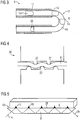
- the waveguide 9 is for example an optical fiber comprising a core 10 and a cladding 11 with slightly lower refractive index (see FIG 3 ).
- the optical fiber In a region 12 of the waveguide 9 serving as a sensing element 13 (see FIG 2 ) the optical fiber is bare of the cladding 11 and therefore in contact with the fluid 4. In other words, the cladding 11 is removed from the waveguide 9 in the region 12 which serves as the sensing element 13.
- Optical signals 14 provided by one of the radiation sources 6, 7, 8 traveling through the optical fiber 10 are schematically shown in FIG 3 .
- the region 12 where the optical fiber is uncladded total reflection of the optical signal 14 takes place at the boundary between the core 10 and the fluid 4. This is due to the different refraction indices of the core 10 of the optical fiber and the fluid 4 as well as to the angle of incidence of the optical signal 14.
- evanescent waves 15 emerge at the boundary between the bent optical fiber 14 and the fluid 4.
- a detector 16 of the monitoring device 5 detects an attenuated optical signal 29.
- the absorption properties of the fluid 4 vary in function of the presence of contaminants and the aging of the fluid 4, by utilizing the evanescent field absorption technique the quality of the fluid 4 can be monitored with the monitoring device 5.
- sensing element 13 for example its geometry, are optimized for the specific operating conditions with respect to the monitored fluid 4, the type of waveguide 9 and the bandwidth of the optical signals 14.
- Providing a plurality of radiation sources 6, 7, 8 allows to collect baseline data and therefore to take into account the intrinsic absorption or scattering properties of the fluid 4. From the different radiation sources 6, 7, 8 respective transmission lines 17, 18, 19 lead to a coupling element in form of an optical coupler 20.
- the waveguide 9 is connected to this optical coupler 20 and thus receives the particular optical signals 14 or optical waves provided by each one of the radiation sources 6, 7, 8.
- the specific detector 16, 21 can be designed for detecting the optical signals 14 of a predetermined number of wavelengths or bandwidths.
- an optical splitter 22 can be connected to the waveguide 9 downstream of the sensing element 13. This optical splitter 22 distributes the attenuated optical signals 14 to the appropriate detector 16, 21 via transmission lines 23, 24 coupled to the optical splitter 22.
- parts of the monitoring device 5 can be situated outside a compartment of a transformer or such a component of the power grid 1, which contains the fluid 4.
- optical penetrators can be utilized in order to introduce the waveguide 9 into the fluid 4 while other parts of the monitoring device 5 are not submerged in the fluid 4.
- the monitoring device 5 also comprises a control unit 25 which operates the radiation sources 6, 7, 8 and the detectors 16, 21.
- the control unit 25 can for example put the radiation sources 6, 7, 8 on standby or turn the radiation sources 6, 7, 8 off for prolonged periods of time and activate the radiation sources 6, 7, 8 just when monitoring of the fluid 4 is required. Also the control unit can turn on the radiation sources 6, 7, 8 subsequently.
- the radiation sources 6, 7, 8, the detectors 16, 21 and the control unit 25 are submerged into the fluid 4 and designed to withstand high pressure, i.e. a pressure of up to 300 bar.
- high pressure i.e. a pressure of up to 300 bar.
- the evanescent waves 15 propagate in the fluid 4 to be examined.
- the parts of the optical signals 14 situated in the fluid 4 in FIG 3 schematically illustrate the optical power distribution and thus the evanescent field absorption.
- the resulting signal attenuation will be a function of the properties of this fluid 4 and the design of the sensing element 13.
- the geometry of the sensing element 13 is optimized for the particular application. However, it is desirable to assure that the optical signals 14 travel in an undisturbed manner to the region 12 and from the region 12 to the detectors 16, 21.
- FIG 4 shows a mode scrambler 26, which can be utilized to form bends 27 in the optical fiber utilized as the waveguide 9. This results in an optimized light power distribution over the cross section of the optical fiber, wherein the distribution of modes will remain stable over long distances.
- FIG 5 shows an alternative sensing element 13 design wherein it is designed as a planar waveguide 9 having a planar surface 28 being in contact with the fluid 4. Utilizing such a planar waveguide 9 instead of the optical fiber with removed cladding 11 also allows the detection of attenuated optical signals with the detectors 16, 21.
- the optical signal 14 coming from one of the radiation sources 6, 7, 8 is shown to produce evanescent waves 15 at the boundary between the planar surface 28 of the waveguide 9 and the fluid 4.
- the attenuated signal 29 is then conveyed to one of the detectors 16, 21.
- the sensing element 13 schematically shown in FIG 5 is also designed to implement the EFA technique as the attenuation of the optical signal is based on the attenuated total reflectance (ATR).
- ATR attenuated total reflectance
- bandwidths or wavelengths in the UV-VIS, NIR or MIR spectral ranges may be utilized in order to detect impurities in the dielectric fluid 4.
- a dielectric fluid 4 has been investigated using optical absorption spectroscopy.
- This dielectric fluid 4 is a synthetic pentaerythritol ester which is utilized as transformer dielectric fluid.
- the reference oil or fluid 4 is considered clear.
- contaminants that may be present in this fluid 4. These include but are not limited to the following: Water, ester base-stock breakdown products such as carboxylic acid and pentaerythritol. Also, dissolved carbon dioxide can be present as contaminant in the fluid 4 and detected with the monitoring device 5.
- well recognizable absorption bands for water are approximately between 5300 to 5220 cm -1 , 3700 to 3600 cm -1 , and 1640 to 1605 cm -1 .
- Wave numbers which are particularly appropriate to detect the absorption of light energy via evanescent waves caused by carboxylic acids are approximately between 3560 and 3460 cm -1 , whereas the bandwidth to detect pentaerythritol is between 3400 and 3200 cm -1 .
- the bandwidth for dissolved carbon dioxide is approximately between 2345 and 2330 cm -1 .
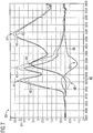
- FIG 6 shows a graph 30 representing UV-VIS transmission spectra of samples of the investigated fluid 4, which are degraded in different conditions.
- the wavelength in nm is indicated and on an ordinate 32 the transmission in percent.
- a curves 33, 34 represents the uncontaminated sample.
- Further curves 35, 36, 37, 38 represent the samples of different conditions or different aging times. As can be seen, for example, from the curve 38 the corresponding sample shows a much lower transmission over the whole range of wavelengths than the sample represented by the curve 33. This is due to the presence of contaminants and the aging of the fluid 4 in the corresponding sample.
- FIG 7 shows another graph 39 with MIR differential absorption spectra of the samples, wherein on an abscissa 40 the wave number in cm -1 is indicated and on an ordinate 41 the absorption coefficient in cm -1 .
- an uncontaminated sample is used as a reference and curves 42, 43, 44, 45, 46 represent a ratio between corresponding samples and the reference sample.
- This differential absorption evaluation illustrates particularly well how the contaminants expected to be present in the samples can be determined. For example, deviations in the forms of peaks 47 or a minimum 48 in the curves 42, 43 and 44 respectively indicate the presence of water.
- peaks 49 and a minimum 50 in curves 44, 45, 46 respectively indicate the presence of carboxylic acids in the samples.
- peaks 51 in the curves 44, 45 indicate the presence of pentaerythritol in two of the samples.
- the monitoring device 5 shown in FIG 2 thus provides a cost effective, safe and reliable tool for quality monitoring of an isolating fluid 4 in a remote, and in particular subsea equipment.
- the monitoring device 5 utilizes the evanescent field absorption technique, in particular by implementing the optical fiber (see FIG 3 ) or another waveguide 9 (see FIG 5 ) to monitor light absorption in the examined fluid 4 at specific bandwidths under subsea conditions.
- the bandwidths comprise in particular wavelengths in the NIR, MIR or UV-VIS spectral range.
Landscapes
- Physics & Mathematics (AREA)
- Health & Medical Sciences (AREA)
- Life Sciences & Earth Sciences (AREA)
- Chemical & Material Sciences (AREA)
- Analytical Chemistry (AREA)
- Biochemistry (AREA)
- General Health & Medical Sciences (AREA)
- General Physics & Mathematics (AREA)
- Immunology (AREA)
- Pathology (AREA)
- Investigating Or Analysing Materials By Optical Means (AREA)
Claims (6)
- Überwachungsvorrichtung (5) zur Überwachung eines Fluids (4) in einer Unterwasservorrichtung (1), umfassend:einen Wellenleiter (9) mit einem Erfassungselement (13), das mit dem Fluid (4) in Kontakt steht, wobei der Wellenleiter (9) eine optische Faser mit einem Kern (10) umfasst,eine Mehrzahl von Strahlungsquellen (6, 7, 8), die über eine Mehrzahl von ersten Übertragungsleitungen (17, 18, 19) und ein erstes Koppelelement (20), das dazu ausgestaltet ist, die Mehrzahl von ersten Übertragungsleitungen (17, 18, 19) von der Mehrzahl von Strahlungsquellen (6, 7, 8) in einen Teil des Wellenleiters (9), der das Erfassungselement (13) umfasst, zusammenzuführen, mit dem Erfassungselement (13) in Kommunikation steht,eine Mehrzahl von Detektoren (16, 21), die über einen optischen Splitter (22) und eine Mehrzahl von zweiten Übertragungsleitungen (23, 24) mit dem Erfassungselement (13) in Kommunikation steht,eine Steuereinheit (25), die dazu ausgebildet ist, die Mehrzahl von Strahlungsquellen (6, 7, 8) und die Mehrzahl von Detektoren (16, 21) zu betreiben, und dazu ausgebildet ist, die Mehrzahl von Strahlungsquellen (6, 7, 8) in den Bereitschaftsmodus zu setzen oder die Mehrzahl von Strahlungsquellen (6, 7, 8) für längere Zeiträume auszuschalten und die Mehrzahl von Strahlungsquellen (6, 7, 8) genau dann zu aktivieren, wenn eine Überwachung des Fluids (4) erforderlich ist,wobei der Wellenleiter (9) wirksam mit dem ersten Koppelelement (20) und dem optischen Splitter (22) verbunden ist,wobei die Mehrzahl von Strahlungsquellen (6, 7, 8) eine Mehrzahl von optischen Signalen (14) in den Wellenleiter (9) einspeist und wobei jede der Mehrzahl von Strahlungsquellen (6, 7, 8) dazu ausgestaltet ist, die optischen Signale (14) über einen Bereich von Wellenlängen in den Wellenleiter (9) einzuspeisen,
wobei der Bereich von Wellenlängen mindestens teilweise Wellenlängen entspricht, die in einem größeren Umfang durch einen bestimmten Verunreinigungsstoff in dem Fluid als durch andere Verunreinigungsstoffe gedämpft werden,wobei das Erfassungselement (13) als ein Bereich (12) des Wellenleiters (9) ausgestaltet ist, in dem der Kern (10) mindestens teilweise frei von einer Umhüllung (11) ist,wobei die Mehrzahl von Detektoren (16, 21) dazu ausgestaltet ist, die optischen Signale einer vorbestimmten Anzahl von Wellenlängen und ein in den Wellenleiter (9) eingespeistes gedämpftes optisches Signal (29) zu detektieren, wobei die Dämpfung durch Evaneszenzfeldabsorption durch das Fluid (4) verursacht wird, wobei der optische Splitter (22) dazu ausgestaltet ist, die gedämpften optischen Signale der Mehrzahl von Strahlungsquellen (6, 7, 8) an die Mehrzahl von Detektoren (16, 21) zu verteilen, undwobei die Steuereinheit (25) dazu ausgestaltet ist, teilweise in das Fluid (4) getaucht zu sein und einem in dem Fluid (4) herrschenden Druck von 300 Bar standzuhalten. - Überwachungsvorrichtung (5) nach Anspruch 1, wobei die optischen Signale (14) im ultraviolett-sichtbaren und/oder nahen infraroten und/oder mittleren infraroten Spektralbereich eingespeist werden.
- Überwachungsvorrichtung (5) nach Anspruch 1 oder 2, wobei die mindestens eine Strahlungsquelle (6, 7, 8) und der mindestens eine Detektor (16, 21) dazu ausgestaltet sind, teilweise in das Fluid (4) getaucht zu sein und einem in dem Fluid (4) herrschenden Druck von 300 Bar standzuhalten.
- Überwachungsvorrichtung (5) nach einem der Ansprüche 1 bis 3, wobei die Steuereinheit (25) dazu ausgebildet ist, jede der Mehrzahl von Strahlungsquellen (6, 7, 8) einzeln nacheinander einzuschalten.
- Überwachungsvorrichtung (5) nach Anspruch 1, ferner umfassend mindestens einen Modenmischer (26), der dazu ausgestaltet ist, eine Mehrzahl von Biegungen (27) in der optischen Faser zu schaffen.
- Verfahren zur Überwachung eines Fluids (4) in einer Unterwasservorrichtung (1), das die folgenden Schritte umfasst:Bringen eines Wellenleiters (9) mit einem Erfassungselement (13) in Kontakt mit dem Fluid (4), wobei der Wellenleiter (9) eine optische Faser in einem Kern (10) umfasst,Betreiben einer Mehrzahl von Strahlungsquellen (6, 7, 8) und einer Mehrzahl von Detektoren (16, 21) und Setzen der Mehrzahl von Strahlungsquellen (6, 7, 8) in den Bereitschaftsmodus oder Ausschalten der Mehrzahl von Strahlungsquellen (6, 7, 8) für längere Zeiträume auszuschalten und Aktivieren der Mehrzahl von Strahlungsquellen (6, 7, 8) genau dann, wenn eine Überwachung des Fluids (4) mit einer Steuereinheit (25) erforderlich ist,Bereitstellen einer Mehrzahl von optischen Signalen (14) aus einer Mehrzahl von Strahlungsquellen (6, 7, 8), die über ein erstes Koppelelement (20) und eine Mehrzahl von ersten Übertragungsleitungen (17, 18, 19) mit dem Erfassungselement (13) in Kommunikation steht, wobei das erste Koppelelement (20) dazu ausgestaltet ist, die Mehrzahl von ersten Übertragungsleitungen (17, 18, 19) von der Mehrzahl von Strahlungsquellen (6, 7, 8) in einen Teil des Wellenleiters (9), der das Erfassungselement (13) umfasst, zusammenzuführen,Einspeisen der Mehrzahl von optischen Signalen (14) in den Wellenleiter (9) über einen Bereich von Wellenlängen, wobei der Bereich von Wellenlängen mindestens teilweise Wellenlängen entspricht, die in einem größeren Umfang durch einen bestimmten Verunreinigungsstoff in dem Fluid als durch andere Verunreinigungsstoffe gedämpft werden,wobei das Erfassungselement (13) als ein Bereich (12) des Wellenleiters (9), in dem der Kern (10) mindestens teilweise frei von einer Umhüllung (11) ist, ausgestaltet und fähig ist, ein Evaneszenzfeldabsorptionsverfahren zu implementieren, wodurch ein gedämpftes optisches Signal (29) bereitgestellt wird,Detektieren der optischen Signale einer vorbestimmten Anzahl von Wellenlängen und des in den Wellenleiter (9) eingespeisten gedämpften optischen Signals (29) durch die Mehrzahl von Detektoren (16, 21) über einen optischen Splitter (22) und eine Mehrzahl von zweiten Übertragungsleitungen (23, 24), wobei der optische Splitter (22) dazu ausgestaltet ist, die gedämpften optischen Signale der Mehrzahl von Strahlungsquellen (6, 7, 8) an die Mehrzahl von Detektoren (16, 21) zu verteilen,wobei die Dämpfung durch Evaneszenzfeldabsorption durch das Fluid (4) verursacht wird undwobei die Steuereinheit (25) teilweise in das Fluid (4) getaucht und dazu ausgestaltet ist, einem in dem Fluid (4) herrschenden Druck von 300 Bar standzuhalten.
Applications Claiming Priority (1)
| Application Number | Priority Date | Filing Date | Title |
|---|---|---|---|
| PCT/RU2013/000385 WO2014182190A1 (en) | 2013-05-07 | 2013-05-07 | Device and method for monitoring a fluid in subsea equipment |
Publications (2)
| Publication Number | Publication Date |
|---|---|
| EP2981808A1 EP2981808A1 (de) | 2016-02-10 |
| EP2981808B1 true EP2981808B1 (de) | 2021-11-10 |
Family
ID=49684055
Family Applications (1)
| Application Number | Title | Priority Date | Filing Date |
|---|---|---|---|
| EP13799123.8A Active EP2981808B1 (de) | 2013-05-07 | 2013-05-07 | Vorrichtung und verfahren zur überwachung eines fluids in einer unterwasservorrichtung |
Country Status (3)
| Country | Link |
|---|---|
| US (1) | US9778182B2 (de) |
| EP (1) | EP2981808B1 (de) |
| WO (1) | WO2014182190A1 (de) |
Families Citing this family (2)
| Publication number | Priority date | Publication date | Assignee | Title |
|---|---|---|---|---|
| US10455730B2 (en) | 2018-03-08 | 2019-10-22 | Saudi Arabian Oil Company | Thermal control system |
| CN112782085B (zh) * | 2021-01-28 | 2023-12-19 | 韩丹丹 | 基于复合光学的充油设备油中溶解气体监测装置及方法 |
Family Cites Families (12)
| Publication number | Priority date | Publication date | Assignee | Title |
|---|---|---|---|---|
| US4887879A (en) | 1988-01-25 | 1989-12-19 | The Trustees Of Columbia University In The City Of New York | Fiber optic tap |
| US5712934A (en) * | 1996-07-25 | 1998-01-27 | Johnson; Douglas M. | Fiber optic infrared sensor |
| US6118520A (en) * | 1996-12-18 | 2000-09-12 | The Dow Chemical Company | Dual analysis probe |
| GB0405821D0 (en) | 2004-03-15 | 2004-04-21 | Evanesco Ltd | Fluid monitoring apparatus and methods |
| US7672544B2 (en) * | 2005-05-26 | 2010-03-02 | Mitsubishi Electric Corporation | Optical fiber sensor |
| US8040582B2 (en) * | 2008-10-16 | 2011-10-18 | Topcon Medical Laser Systems, Inc. | Light beam delivery system with power, wavelength and spot size control |
| US7969571B2 (en) | 2009-01-15 | 2011-06-28 | Baker Hughes Incorporated | Evanescent wave downhole fiber optic spectrometer |
| GB0903715D0 (en) | 2009-03-04 | 2009-04-15 | Yorkshire Building Services Whitwell Ltd | Thermal insulation product |
| US8927924B2 (en) * | 2009-03-06 | 2015-01-06 | Fmc Technologies, Inc. | Optical leak detector for subsea equipment |
| US8218133B2 (en) | 2010-09-16 | 2012-07-10 | Sondex Limited | Refractive index tool and method |
| CN201859115U (zh) | 2010-11-13 | 2011-06-08 | 张春华 | 一种多通道流体光谱分析仪 |
| WO2012094094A2 (en) * | 2011-01-04 | 2012-07-12 | Exxonmobil Research And Engineering Company | Method and apparatus for a mid-infrared (mir) system for real time detection of petroleum in colloidal suspensions of sediments and drilling muds during drilling, logging, and production operations |
-
2013
- 2013-05-07 WO PCT/RU2013/000385 patent/WO2014182190A1/en not_active Ceased
- 2013-05-07 US US14/889,585 patent/US9778182B2/en active Active
- 2013-05-07 EP EP13799123.8A patent/EP2981808B1/de active Active
Non-Patent Citations (1)
| Title |
|---|
| None * |
Also Published As
| Publication number | Publication date |
|---|---|
| US9778182B2 (en) | 2017-10-03 |
| WO2014182190A1 (en) | 2014-11-13 |
| EP2981808A1 (de) | 2016-02-10 |
| US20160077003A1 (en) | 2016-03-17 |
Similar Documents
| Publication | Publication Date | Title |
|---|---|---|
| Jiang et al. | Multi-gas detection in power transformer oil based on tunable diode laser absorption spectrum | |
| KR101681561B1 (ko) | 변압기 절연유의 온도 및 가스 검출 장치 | |
| US20050088646A1 (en) | Apparatus for measuring oil oxidation using fluorescent light reflected from oil | |
| KR20000065114A (ko) | 통신광섬유를통한스펙트럼정보송신 | |
| Meitei et al. | Review on monitoring of transformer insulation oil using optical fiber sensors | |
| Blue et al. | Infrared detection of transformer insulation degradation due to accelerated thermal aging | |
| WO2019207680A1 (ja) | 油入電気機器の診断方法 | |
| Pesavento et al. | Towards the development of cascaded surface plasmon resonance POF sensors exploiting gold films and synthetic recognition elements for detection of contaminants in transformer oil | |
| CN114720516B (zh) | 一种变压器油老化程度的评估方法、装置和传感系统 | |
| CN113310596A (zh) | 基于纯光纤传感的变压器油中气体及温度监测系统及方法 | |
| EP2981808B1 (de) | Vorrichtung und verfahren zur überwachung eines fluids in einer unterwasservorrichtung | |
| Onn et al. | Fiber Bragg grating sensor for detecting ageing transformer oil | |
| CN114062274A (zh) | 一种用于油中溶解气体检测的光纤光声传感系统及方法 | |
| De Maria et al. | Frequency dielectric spectroscopy and an innovative optical sensor to assess oil-paper degradation | |
| Rashed et al. | Optical Spectroscopy Techniques for Condition Assessment and Fault Diagnosis of Power Transformer Insulation: A Critical Review on Technologies, Methods, and Standards | |
| Schwarz et al. | Diagnostic methods for transformers | |
| CN103930770B (zh) | 用于在线监视电力变压器中呋喃类物质的传感器结构 | |
| US10107742B2 (en) | Method and system for monitoring the quality of fluids | |
| CN218848268U (zh) | 一种变压器套管多阵元光纤微水与超声局放联合检测系统 | |
| Firouzimagham et al. | Online transformer oil analysis based on spectroscopy technique and machine learning classifier: Experimental setup | |
| Seiffadini et al. | Correlation between the optical properties and the degree of polymerisation of transformer insulation paper | |
| Elele et al. | Refractometric Fibre Optic Sensing Framework for Aged Rapeseed Natural Ester Transformer Oil | |
| CN115825659B (zh) | 一种变压器套管多阵元光纤微水与超声局放联合检测系统 | |
| De Maria et al. | Toward an optical monitoring of chemical markers in transformers insulating oil | |
| CN217033599U (zh) | 一种用于油中溶解气体检测的光纤光声传感系统 |
Legal Events
| Date | Code | Title | Description |
|---|---|---|---|
| PUAI | Public reference made under article 153(3) epc to a published international application that has entered the european phase |
Free format text: ORIGINAL CODE: 0009012 |
|
| 17P | Request for examination filed |
Effective date: 20151102 |
|
| AK | Designated contracting states |
Kind code of ref document: A1 Designated state(s): AL AT BE BG CH CY CZ DE DK EE ES FI FR GB GR HR HU IE IS IT LI LT LU LV MC MK MT NL NO PL PT RO RS SE SI SK SM TR |
|
| AX | Request for extension of the european patent |
Extension state: BA ME |
|
| DAX | Request for extension of the european patent (deleted) | ||
| RAP1 | Party data changed (applicant data changed or rights of an application transferred) |
Owner name: SIEMENS AKTIENGESELLSCHAFT |
|
| STAA | Information on the status of an ep patent application or granted ep patent |
Free format text: STATUS: EXAMINATION IS IN PROGRESS |
|
| 17Q | First examination report despatched |
Effective date: 20180425 |
|
| RAP1 | Party data changed (applicant data changed or rights of an application transferred) |
Owner name: SIEMENS ENERGY GLOBAL GMBH & CO. KG |
|
| GRAP | Despatch of communication of intention to grant a patent |
Free format text: ORIGINAL CODE: EPIDOSNIGR1 |
|
| STAA | Information on the status of an ep patent application or granted ep patent |
Free format text: STATUS: GRANT OF PATENT IS INTENDED |
|
| INTG | Intention to grant announced |
Effective date: 20210330 |
|
| RAP1 | Party data changed (applicant data changed or rights of an application transferred) |
Owner name: SIEMENS ENERGY AS |
|
| GRAS | Grant fee paid |
Free format text: ORIGINAL CODE: EPIDOSNIGR3 |
|
| GRAA | (expected) grant |
Free format text: ORIGINAL CODE: 0009210 |
|
| STAA | Information on the status of an ep patent application or granted ep patent |
Free format text: STATUS: THE PATENT HAS BEEN GRANTED |
|
| AK | Designated contracting states |
Kind code of ref document: B1 Designated state(s): AL AT BE BG CH CY CZ DE DK EE ES FI FR GB GR HR HU IE IS IT LI LT LU LV MC MK MT NL NO PL PT RO RS SE SI SK SM TR |
|
| REG | Reference to a national code |
Ref country code: GB Ref legal event code: FG4D |
|
| REG | Reference to a national code |
Ref country code: AT Ref legal event code: REF Ref document number: 1446528 Country of ref document: AT Kind code of ref document: T Effective date: 20211115 Ref country code: CH Ref legal event code: EP |
|
| REG | Reference to a national code |
Ref country code: DE Ref legal event code: R096 Ref document number: 602013079991 Country of ref document: DE |
|
| REG | Reference to a national code |
Ref country code: IE Ref legal event code: FG4D |
|
| REG | Reference to a national code |
Ref country code: LT Ref legal event code: MG9D |
|
| REG | Reference to a national code |
Ref country code: NL Ref legal event code: MP Effective date: 20211110 |
|
| REG | Reference to a national code |
Ref country code: NO Ref legal event code: T2 Effective date: 20211110 |
|
| REG | Reference to a national code |
Ref country code: AT Ref legal event code: MK05 Ref document number: 1446528 Country of ref document: AT Kind code of ref document: T Effective date: 20211110 |
|
| PG25 | Lapsed in a contracting state [announced via postgrant information from national office to epo] |
Ref country code: RS Free format text: LAPSE BECAUSE OF FAILURE TO SUBMIT A TRANSLATION OF THE DESCRIPTION OR TO PAY THE FEE WITHIN THE PRESCRIBED TIME-LIMIT Effective date: 20211110 Ref country code: LT Free format text: LAPSE BECAUSE OF FAILURE TO SUBMIT A TRANSLATION OF THE DESCRIPTION OR TO PAY THE FEE WITHIN THE PRESCRIBED TIME-LIMIT Effective date: 20211110 Ref country code: FI Free format text: LAPSE BECAUSE OF FAILURE TO SUBMIT A TRANSLATION OF THE DESCRIPTION OR TO PAY THE FEE WITHIN THE PRESCRIBED TIME-LIMIT Effective date: 20211110 Ref country code: BG Free format text: LAPSE BECAUSE OF FAILURE TO SUBMIT A TRANSLATION OF THE DESCRIPTION OR TO PAY THE FEE WITHIN THE PRESCRIBED TIME-LIMIT Effective date: 20220210 Ref country code: AT Free format text: LAPSE BECAUSE OF FAILURE TO SUBMIT A TRANSLATION OF THE DESCRIPTION OR TO PAY THE FEE WITHIN THE PRESCRIBED TIME-LIMIT Effective date: 20211110 |
|
| PG25 | Lapsed in a contracting state [announced via postgrant information from national office to epo] |
Ref country code: IS Free format text: LAPSE BECAUSE OF FAILURE TO SUBMIT A TRANSLATION OF THE DESCRIPTION OR TO PAY THE FEE WITHIN THE PRESCRIBED TIME-LIMIT Effective date: 20220310 Ref country code: SE Free format text: LAPSE BECAUSE OF FAILURE TO SUBMIT A TRANSLATION OF THE DESCRIPTION OR TO PAY THE FEE WITHIN THE PRESCRIBED TIME-LIMIT Effective date: 20211110 Ref country code: PT Free format text: LAPSE BECAUSE OF FAILURE TO SUBMIT A TRANSLATION OF THE DESCRIPTION OR TO PAY THE FEE WITHIN THE PRESCRIBED TIME-LIMIT Effective date: 20220310 Ref country code: PL Free format text: LAPSE BECAUSE OF FAILURE TO SUBMIT A TRANSLATION OF THE DESCRIPTION OR TO PAY THE FEE WITHIN THE PRESCRIBED TIME-LIMIT Effective date: 20211110 Ref country code: NL Free format text: LAPSE BECAUSE OF FAILURE TO SUBMIT A TRANSLATION OF THE DESCRIPTION OR TO PAY THE FEE WITHIN THE PRESCRIBED TIME-LIMIT Effective date: 20211110 Ref country code: LV Free format text: LAPSE BECAUSE OF FAILURE TO SUBMIT A TRANSLATION OF THE DESCRIPTION OR TO PAY THE FEE WITHIN THE PRESCRIBED TIME-LIMIT Effective date: 20211110 Ref country code: HR Free format text: LAPSE BECAUSE OF FAILURE TO SUBMIT A TRANSLATION OF THE DESCRIPTION OR TO PAY THE FEE WITHIN THE PRESCRIBED TIME-LIMIT Effective date: 20211110 Ref country code: GR Free format text: LAPSE BECAUSE OF FAILURE TO SUBMIT A TRANSLATION OF THE DESCRIPTION OR TO PAY THE FEE WITHIN THE PRESCRIBED TIME-LIMIT Effective date: 20220211 Ref country code: ES Free format text: LAPSE BECAUSE OF FAILURE TO SUBMIT A TRANSLATION OF THE DESCRIPTION OR TO PAY THE FEE WITHIN THE PRESCRIBED TIME-LIMIT Effective date: 20211110 |
|
| PG25 | Lapsed in a contracting state [announced via postgrant information from national office to epo] |
Ref country code: SM Free format text: LAPSE BECAUSE OF FAILURE TO SUBMIT A TRANSLATION OF THE DESCRIPTION OR TO PAY THE FEE WITHIN THE PRESCRIBED TIME-LIMIT Effective date: 20211110 Ref country code: SK Free format text: LAPSE BECAUSE OF FAILURE TO SUBMIT A TRANSLATION OF THE DESCRIPTION OR TO PAY THE FEE WITHIN THE PRESCRIBED TIME-LIMIT Effective date: 20211110 Ref country code: RO Free format text: LAPSE BECAUSE OF FAILURE TO SUBMIT A TRANSLATION OF THE DESCRIPTION OR TO PAY THE FEE WITHIN THE PRESCRIBED TIME-LIMIT Effective date: 20211110 Ref country code: EE Free format text: LAPSE BECAUSE OF FAILURE TO SUBMIT A TRANSLATION OF THE DESCRIPTION OR TO PAY THE FEE WITHIN THE PRESCRIBED TIME-LIMIT Effective date: 20211110 Ref country code: DK Free format text: LAPSE BECAUSE OF FAILURE TO SUBMIT A TRANSLATION OF THE DESCRIPTION OR TO PAY THE FEE WITHIN THE PRESCRIBED TIME-LIMIT Effective date: 20211110 Ref country code: CZ Free format text: LAPSE BECAUSE OF FAILURE TO SUBMIT A TRANSLATION OF THE DESCRIPTION OR TO PAY THE FEE WITHIN THE PRESCRIBED TIME-LIMIT Effective date: 20211110 |
|
| REG | Reference to a national code |
Ref country code: DE Ref legal event code: R097 Ref document number: 602013079991 Country of ref document: DE |
|
| PLBE | No opposition filed within time limit |
Free format text: ORIGINAL CODE: 0009261 |
|
| STAA | Information on the status of an ep patent application or granted ep patent |
Free format text: STATUS: NO OPPOSITION FILED WITHIN TIME LIMIT |
|
| 26N | No opposition filed |
Effective date: 20220811 |
|
| PG25 | Lapsed in a contracting state [announced via postgrant information from national office to epo] |
Ref country code: AL Free format text: LAPSE BECAUSE OF FAILURE TO SUBMIT A TRANSLATION OF THE DESCRIPTION OR TO PAY THE FEE WITHIN THE PRESCRIBED TIME-LIMIT Effective date: 20211110 |
|
| PG25 | Lapsed in a contracting state [announced via postgrant information from national office to epo] |
Ref country code: SI Free format text: LAPSE BECAUSE OF FAILURE TO SUBMIT A TRANSLATION OF THE DESCRIPTION OR TO PAY THE FEE WITHIN THE PRESCRIBED TIME-LIMIT Effective date: 20211110 |
|
| REG | Reference to a national code |
Ref country code: DE Ref legal event code: R119 Ref document number: 602013079991 Country of ref document: DE |
|
| REG | Reference to a national code |
Ref country code: CH Ref legal event code: PL |
|
| REG | Reference to a national code |
Ref country code: BE Ref legal event code: MM Effective date: 20220531 |
|
| PG25 | Lapsed in a contracting state [announced via postgrant information from national office to epo] |
Ref country code: MC Free format text: LAPSE BECAUSE OF FAILURE TO SUBMIT A TRANSLATION OF THE DESCRIPTION OR TO PAY THE FEE WITHIN THE PRESCRIBED TIME-LIMIT Effective date: 20211110 Ref country code: LU Free format text: LAPSE BECAUSE OF NON-PAYMENT OF DUE FEES Effective date: 20220507 Ref country code: LI Free format text: LAPSE BECAUSE OF NON-PAYMENT OF DUE FEES Effective date: 20220531 Ref country code: CH Free format text: LAPSE BECAUSE OF NON-PAYMENT OF DUE FEES Effective date: 20220531 |
|
| PG25 | Lapsed in a contracting state [announced via postgrant information from national office to epo] |
Ref country code: IE Free format text: LAPSE BECAUSE OF NON-PAYMENT OF DUE FEES Effective date: 20220507 Ref country code: FR Free format text: LAPSE BECAUSE OF NON-PAYMENT OF DUE FEES Effective date: 20220531 |
|
| PG25 | Lapsed in a contracting state [announced via postgrant information from national office to epo] |
Ref country code: IT Free format text: LAPSE BECAUSE OF FAILURE TO SUBMIT A TRANSLATION OF THE DESCRIPTION OR TO PAY THE FEE WITHIN THE PRESCRIBED TIME-LIMIT Effective date: 20211110 Ref country code: DE Free format text: LAPSE BECAUSE OF NON-PAYMENT OF DUE FEES Effective date: 20221201 Ref country code: BE Free format text: LAPSE BECAUSE OF NON-PAYMENT OF DUE FEES Effective date: 20220531 |
|
| PG25 | Lapsed in a contracting state [announced via postgrant information from national office to epo] |
Ref country code: HU Free format text: LAPSE BECAUSE OF FAILURE TO SUBMIT A TRANSLATION OF THE DESCRIPTION OR TO PAY THE FEE WITHIN THE PRESCRIBED TIME-LIMIT; INVALID AB INITIO Effective date: 20130507 |
|
| PG25 | Lapsed in a contracting state [announced via postgrant information from national office to epo] |
Ref country code: MK Free format text: LAPSE BECAUSE OF FAILURE TO SUBMIT A TRANSLATION OF THE DESCRIPTION OR TO PAY THE FEE WITHIN THE PRESCRIBED TIME-LIMIT Effective date: 20211110 Ref country code: CY Free format text: LAPSE BECAUSE OF FAILURE TO SUBMIT A TRANSLATION OF THE DESCRIPTION OR TO PAY THE FEE WITHIN THE PRESCRIBED TIME-LIMIT Effective date: 20211110 |
|
| PG25 | Lapsed in a contracting state [announced via postgrant information from national office to epo] |
Ref country code: TR Free format text: LAPSE BECAUSE OF FAILURE TO SUBMIT A TRANSLATION OF THE DESCRIPTION OR TO PAY THE FEE WITHIN THE PRESCRIBED TIME-LIMIT Effective date: 20211110 |
|
| PG25 | Lapsed in a contracting state [announced via postgrant information from national office to epo] |
Ref country code: MT Free format text: LAPSE BECAUSE OF FAILURE TO SUBMIT A TRANSLATION OF THE DESCRIPTION OR TO PAY THE FEE WITHIN THE PRESCRIBED TIME-LIMIT Effective date: 20211110 |
|
| PGFP | Annual fee paid to national office [announced via postgrant information from national office to epo] |
Ref country code: NO Payment date: 20250520 Year of fee payment: 13 |
|
| PGFP | Annual fee paid to national office [announced via postgrant information from national office to epo] |
Ref country code: GB Payment date: 20260323 Year of fee payment: 14 |