EP2980924A1 - Connector - Google Patents
Connector Download PDFInfo
- Publication number
- EP2980924A1 EP2980924A1 EP15176916.3A EP15176916A EP2980924A1 EP 2980924 A1 EP2980924 A1 EP 2980924A1 EP 15176916 A EP15176916 A EP 15176916A EP 2980924 A1 EP2980924 A1 EP 2980924A1
- Authority
- EP
- European Patent Office
- Prior art keywords
- connector
- housing
- mating
- lock
- hooked
- Prior art date
- Legal status (The legal status is an assumption and is not a legal conclusion. Google has not performed a legal analysis and makes no representation as to the accuracy of the status listed.)
- Granted
Links
Images




Classifications
-
- H—ELECTRICITY
- H01—ELECTRIC ELEMENTS
- H01R—ELECTRICALLY-CONDUCTIVE CONNECTIONS; STRUCTURAL ASSOCIATIONS OF A PLURALITY OF MUTUALLY-INSULATED ELECTRICAL CONNECTING ELEMENTS; COUPLING DEVICES; CURRENT COLLECTORS
- H01R13/00—Details of coupling devices of the kinds covered by groups H01R12/70 or H01R24/00 - H01R33/00
- H01R13/62—Means for facilitating engagement or disengagement of coupling parts or for holding them in engagement
- H01R13/639—Additional means for holding or locking coupling parts together, after engagement, e.g. separate keylock, retainer strap
-
- H—ELECTRICITY
- H01—ELECTRIC ELEMENTS
- H01R—ELECTRICALLY-CONDUCTIVE CONNECTIONS; STRUCTURAL ASSOCIATIONS OF A PLURALITY OF MUTUALLY-INSULATED ELECTRICAL CONNECTING ELEMENTS; COUPLING DEVICES; CURRENT COLLECTORS
- H01R13/00—Details of coupling devices of the kinds covered by groups H01R12/70 or H01R24/00 - H01R33/00
- H01R13/40—Securing contact members in or to a base or case; Insulating of contact members
- H01R13/42—Securing in a demountable manner
- H01R13/436—Securing a plurality of contact members by one locking piece or operation
-
- H—ELECTRICITY
- H01—ELECTRIC ELEMENTS
- H01R—ELECTRICALLY-CONDUCTIVE CONNECTIONS; STRUCTURAL ASSOCIATIONS OF A PLURALITY OF MUTUALLY-INSULATED ELECTRICAL CONNECTING ELEMENTS; COUPLING DEVICES; CURRENT COLLECTORS
- H01R13/00—Details of coupling devices of the kinds covered by groups H01R12/70 or H01R24/00 - H01R33/00
- H01R13/46—Bases; Cases
- H01R13/502—Bases; Cases composed of different pieces
- H01R13/506—Bases; Cases composed of different pieces assembled by snap action of the parts
-
- H—ELECTRICITY
- H01—ELECTRIC ELEMENTS
- H01R—ELECTRICALLY-CONDUCTIVE CONNECTIONS; STRUCTURAL ASSOCIATIONS OF A PLURALITY OF MUTUALLY-INSULATED ELECTRICAL CONNECTING ELEMENTS; COUPLING DEVICES; CURRENT COLLECTORS
- H01R13/00—Details of coupling devices of the kinds covered by groups H01R12/70 or H01R24/00 - H01R33/00
- H01R13/62—Means for facilitating engagement or disengagement of coupling parts or for holding them in engagement
- H01R13/627—Snap or like fastening
- H01R13/6271—Latching means integral with the housing
- H01R13/6273—Latching means integral with the housing comprising two latching arms
Definitions
- This invention relates to a connector which is connected with a cable.
- Patent Document 1 JP-A 2009-4247 discloses a connector 900 which is connected with a cable 970 and which is mated with a mating connector 950 in a mating direction.
- the connector 900 of Patent Document 1 comprises a housing 910 and a contact 920.
- the housing 910 is provided with a lock portion 912 and an operation portion 914.
- the mating connector 950 of Patent Document 1 is provided with a mating lock portion 952.
- the lock portion 912 locks the mating lock portion 952.
- the operation portion 914 is operated, a lock of the lock portion 912 against the mating lock portion 952 is released.
- the contact 920 is connected with the cable 970.
- the cable 970 extends in a perpendicular direction perpendicular to the mating direction of the connector 900 and the mating connector 950.
- the perpendicular direction is a Z-direction.
- the mating direction is an X-direction.
- a structure of the connector 900 of Patent Document 1 has a drawback that it is difficult to connect the cable 970 with the contact 920 and to assemble the housing 910 and the contact 920 connected with the cable 970.
- the connector comprises a first housing, a second housing and a contact.
- the first housing accommodates, at least in part, the contact.
- the contact is provided with a cable holding portion which holds an end of a cable so that the cable extends in a predetermined direction.
- the second housing is attached to the first housing to hold the contact in cooperation with the first housing.
- the second housing is provided with a hooked portion, a spring portion, an operation portion and a lock portion.
- the spring portion is resiliently deformable. The operation portion and the lock portion are supported by the spring portion.
- the lock portion locks the mating lock portion when the connector and the mating connector are mated with each other.
- the hooked portion is a portion which is hooked by a finger upon operation of the operation portion.
- the hooked portion is positioned apart from the operation portion in the predetermined direction. The operation portion releases a lock of the lock portion against the mating lock portion when operated to be moved toward the hooked portion.
- a member which holds the contact is separated into two portions of the first housing and the second housing. After the contacts is, at least in part, accommodated in the first housing, the second hosing is attached to the first housing so that the second housing holds the contact in cooperation with the first housing. Therefore, the connector can be fabricated easily even if the contact is connected with the cable.
- the operation portion and the hooked portion are positioned apart from each other in an extending direction in which the cable extends, wherein the hooked portion is hooked by a finger upon operation of the operation portion, and the extending direction is the predetermined direction. Accordingly, in a state where a plurality of the connectors are mated with a plurality of the mating connectors and are arranged in a row, one of the connectors can be easily released from the mating connector corresponding thereto while the remaining connectors or the cables connected to the remaining connectors do not obstruct the release operation.
- a connector 100 is connected with cables 600.
- Each of the cables 600 which is connected with the connector 100 extends in a predetermined direction or a Z-direction.
- the predetermined direction is an up-down direction.
- the connector 100 is mateable with a mating connector 500 along a mating direction, or an X-direction.
- the mating direction of the connector 100 and the mating connector 500 is perpendicular to or intersects with the predetermined direction in which each of the cables 600 extends as shown in Fig. 1 .
- the mating direction of the present embodiment is referred to as a front-rear direction, too.
- the mating connector 500 has a mating fitting portion 505 which is mated with the connector 100.
- the mating fitting portion 505 is provided with two mating lock portions 510.
- Each of the mating lock portions 510 of the present embodiment is a protrusion which protrudes upward, or in a positive Z-direction.
- the connector 100 comprises a first housing 200, a second housing 300 and four contacts 400.
- the first housing 200 is made of insulator.
- the second housing 300 is made of insulator.
- Each of the contacts 400 is made of conductor.
- each of the contacts 400 has a contact portion 410, a shoulder portion 420 and a cable holding portion 430.
- the contact portion 410 has a shape parallel to a horizontal plane, namely, a flat plate-like shape.
- the horizontal plane is an XY-plane.
- the cable holding portions 430 hold ends 610 of the cables 600, respectively, so that each of the cables 600 extends in the predetermined direction.
- the shoulder portion 420 couples the contact portion 410 with the cable holding portion 430.
- the connector 100 of the present embodiment is a so-called angled connector. However, the present invention is not limited thereto.
- the connector 100 may be a so-called straight connector.
- the first housing 200 has a fitting portion 210 and an accommodation portion 230.
- the fitting portion 210 is opened at a front end 102, or a positive X-side end, of the connector 100.
- partition walls 220 are provided inside the fitting portion 210 and divide the fitting portion 210 into four spaces. As described later, the four spaces correspond to the four contacts 400, respectively.
- an upper portion 212 of the fitting portion 210 is formed with two openings 214.
- the openings 214 are provided so as to correspond to the mating lock portions 510, respectively, of the mating connector 500 of Fig. 12 .
- the accommodation portion 230 is opened rearward, or in a negative X-direction.
- partition walls 232 are provided inside the accommodation portion 230 and divide the accommodation portion 230 into four spaces. As described later, the four spaces correspond to the four contacts 400, respectively.
- a rear wall 216 of the fitting portion 210 is formed with insertion holes 218 each of which reaches the accommodation portion 230.
- the number of the insertion holes 218 is four.
- the insertion holes 218 correspond to the contacts 400, respectively.
- Each of the insertion holes 218 has an elongated, slit-like shape in a plane, or in a YZ-plane, perpendicular to the front-rear direction.
- each of the contacts 400 is, at least in part, accommodated in the first housing 200.
- the accommodation portion 230 is opened rearward. Accordingly, each of the contacts 400 can be easily accommodated in the first housing 200 even after each of the contacts 400 is connected with the corresponding cable 600.
- an upper portion 234 of the accommodation portion 230 is formed with two first upper engaging portions 236 each of which consists of a hole.
- first lower engaging portions 252 are provided at lower ends, or negative Z-side ends, of two side walls 250 of the accommodation portion 230, respectively.
- Each of the first lower engaging portions 252 consists of a recess which is recessed upward.
- a first positional regulating portion 240 is formed between the fitting portion 210 and the accommodation portion 230.
- the first positional regulating portion 240 of the present embodiment extends in a lateral direction, or a Y-direction.
- the aforementioned first housing 200 is not essentially intended to be deformable. Accordingly, the first housing 200 is made of relatively solid material.
- the second housing 300 described below has a part which is resiliently deformable, it is preferable that the second housing 300 is made of material which is not harder than other material of which the first housing 200 is made. Accordingly, in the present embodiment, the first housing 200 is made of material harder than other material of which the second housing 300 is made. Thus, solidity of the first housing 200 and partial resiliency of the second housing 300 can simultaneously be achieved.
- the second housing 300 has a cover wall 310 which covers the accommodation portion 230.
- the cover wall 310 has a plate-like shape which roughly extends in parallel to a plane, or the YZ-plane, perpendicular to the front-rear direction.
- two second lower engaging portions 312 are provided in the vicinity of a lower end of the cover wall 310. Each of the second lower engaging portions 312 protrudes outward in the lateral direction.
- the second lower engaging portions 312 correspond to the first lower engaging portions 252 (see Fig. 2 ), respectively.
- the second housing 300 is provided with a hooked portion 320.
- the hooked portion 320 is a portion which is hooked by a finger when the connector 100 is released from the mating connector 500.
- the hooked portion 320 of the present embodiment is formed of a planar part which extends rearward and obliquely downward from the lower end of the cover wall 310. Specifically, since the hooked portion 320 intersects with both the mating direction, or the front-rear direction, and the predetermined direction, or the up-down direction, the hooked portion 320 can be easily hooked by a finger.
- the hooked portion 320 is positioned apart from the cables 600 in the mating direction, or in a perpendicular direction perpendicular to an extending direction in which each of the cables 600 extends.
- a distance from an end part of the hooked portion 320 to the cables 600 is equal or larger than a diameter of the cable 600. Accordingly, it is easy to insert a finger between the cables 600 and the hooked portion 320 so that the hooked portion 320 is easily hooked by a finger tip.
- a front surface of the cover wall 310 is formed with a plurality of holding protrusions 330.
- the holding protrusions 330 press the contacts 400 against the first housing 200 when the second housing 300 is attached to the first housing 200.
- the second housing 300 further has a spring support portion 340, a spring portion 350 and a seesaw portion 360.
- the spring support portion 340 extends frontward from an upper end of the cover wall 310. As shown in Fig. 11 , the spring support portion 340 is formed with two second upper engaging portions 342. Each of the second upper engaging portions 342 according the present embodiment is a protrusion which protrudes downward.
- the second housing 300 is pivoted on the second lower engaging portions 312 after the second lower engaging portions 312 are engaged in the first lower engaging portions 252 (see Fig. 2 ) of the first housing 200, respectively, the second upper engaging portions 342 ride on the upper portion 234 (see Fig. 2 ) of the accommodation portion 230 and are then received in the first upper engaging portions 236, respectively (see Fig. 8 ).
- the second housing 300 is attached to the first housing 200.
- the holding protrusions 330 press the contacts 400, which are accommodated in the accommodation portion 230, against the first housing 200 so that each of the contacts 400 is held by the first housing 200 and the second housing 300.
- the spring portion 350 is supported by the spring support portion 340.
- the spring portion 350 is resiliently deformable and supports the seesaw portion 360.
- the seesaw portion 360 has a widened U-like shape when seen from above.
- the seesaw portion 360 has a front portion and a rear portion. The front portion is positioned frontward of the spring portion 350 and the rear portion is positioned rearward of the spring portion 350. The front portion is moved upward when the rear portion is moved downward.
- the seesaw portion 360 is supported by the spring portion 350 so as to be movable in a seesaw manner. In other words, since the spring portion 350, which extends downward from approximately middle of the seesaw portion 360 in the lateral direction, functions as a fulcrum, the seesaw portion 360 is movable in a seesaw manner.
- the seesaw portion 360 is formed with second positional regulating portions 362, an operation portion 370 and lock portions 380.
- the operation portion 370 and the lock portions 380 are supported by the spring portion 350.
- each of the second positional regulating portions 362 is positioned at a position which is positioned slightly rearward of the spring portion 350 and positioned at almost the same position as the spring portion 350.
- the operation portion 370 is formed of a surface of the seesaw portion 360 which is positioned rearward of the spring portion 350.
- the lock portions 380 are formed of holes of the seesaw portion 360 each of which is positioned frontward of the spring portion 350.
- each of the lock portions 380 is moved upward when the operation portion 370 is operated to be pressed downward. As understood from Figs. 12 to 14 , when each of the lock portions 380 is moved upward, the operation portion 370 is moved downward.
- the number of the second positional regulating portions 362 of the present embodiment is two. As shown in Fig. 6 , each of the second positional regulating portions 362 is positioned rearward of the first positional regulating portion 240 and faces the first positional regulating portion 240 in the front-rear direction. Accordingly, even if a large frontward force, namely, a large force toward the first housing 200, is applied to the seesaw portion 360, each of the second positional regulating portions 362 abuts the first positional regulating portion 240 to stop an excessive movement of the seesaw portion 360 so that the spring portion 350 can be prevented from being broken.
- each of the mating lock portions 510 is a protrusion
- each of the lock portions 380 is the corresponding hole.
- the lock portions 380 are positioned in the openings 214, respectively, which are provided on the upper portion 212 of the fitting portion 210. Accordingly, when the mating fitting portion 505 of the mating connector 500 (see Fig.
- each of the lock portions 380 is positioned at a position different from a position of the spring portion 350 in the mating direction as described above, the openings 214 may be provided so as to correspond only to the lock portions 380, respectively. Accordingly, each of the openings 214 which are formed on the first housing 200 can have a relatively reduced size so that the first housing 200 can be secured to have a required strength.
- the operation portion 370 is positioned apart from the hooked portion 320 in the predetermined direction.
- the surface, of which the operation portion 370 is formed extends rearward and obliquely upward at a rear end of the seesaw portion 360.
- the operation portion 370 intersects with both the mating direction, or the front-rear direction, and the predetermined direction, or the up-down direction, so that the operation portion 370 is easily operatable.
- the mating direction of the connector 100 and the mating connector 500 is perpendicular to the extending direction of the cable 600.
- the mating direction of the connector 100 and the mating connector 500 may be same as the extending direction of the cable 600.
- the mating direction is perpendicular to the extending direction of the cable 600 similar to the present embodiment.
- the present embodiment is not limited thereto.
- the number of the contacts 400 may be three or less than three.
- the number of the contacts 400 may be five or more than five.
- each of the mating lock portions 510 is the protrusion and each of the lock portions 380 is the hole.
- the preset invention is not limited thereto.
- Each of the mating lock portions 510 may be a hole while each of the lock portions 380 may be a protrusion.
- mating contacts (not shown) which are included in the mating connector 500 are not exposed outward so that the mating connector 500 has a structure suitable to use as a power supply connector. Accordingly, if the mating connector 500 is used as a power supply connector, it is preferable that each of the lock portions 380 is the holes.
- the lock portions 380 are recesses which correspond to the protrusions of the mating lock portions 510, respectively.
Landscapes
- Details Of Connecting Devices For Male And Female Coupling (AREA)
- Connector Housings Or Holding Contact Members (AREA)
Abstract
Description
- This invention relates to a connector which is connected with a cable.
-
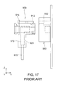
JP-A 2009-4247 connector 900 which is connected with acable 970 and which is mated with amating connector 950 in a mating direction. With reference toFig. 17 , theconnector 900 of Patent Document 1 comprises ahousing 910 and acontact 920. Thehousing 910 is provided with alock portion 912 and anoperation portion 914. Themating connector 950 of Patent Document 1 is provided with amating lock portion 952. When theconnector 900 is mated with themating connector 950, thelock portion 912 locks themating lock portion 952. When theoperation portion 914 is operated, a lock of thelock portion 912 against themating lock portion 952 is released. Thecontact 920 is connected with thecable 970. Thecable 970 extends in a perpendicular direction perpendicular to the mating direction of theconnector 900 and themating connector 950. The perpendicular direction is a Z-direction. The mating direction is an X-direction. - A structure of the
connector 900 of Patent Document 1 has a drawback that it is difficult to connect thecable 970 with thecontact 920 and to assemble thehousing 910 and thecontact 920 connected with thecable 970. - In addition, there is a need that, in a state where a plurality of connectors are mated with a plurality of mating connectors and are arranged in a row, one of the connectors is released from the mating connector corresponding thereto while remaining connectors or cables connected to the remaining connectors do not obstruct the release operation.
- It is therefore an object of the present invention to provide a connector having a structure which enables easy assembly of a housing and a contact connected with a cable and which is capable of satisfying the aforementioned need.
- One aspect (first aspect) of the present invention provides a connector mateable with a mating connector which has a mating lock portion. The connector comprises a first housing, a second housing and a contact. The first housing accommodates, at least in part, the contact. The contact is provided with a cable holding portion which holds an end of a cable so that the cable extends in a predetermined direction. The second housing is attached to the first housing to hold the contact in cooperation with the first housing. The second housing is provided with a hooked portion, a spring portion, an operation portion and a lock portion. The spring portion is resiliently deformable. The operation portion and the lock portion are supported by the spring portion. The lock portion locks the mating lock portion when the connector and the mating connector are mated with each other. The hooked portion is a portion which is hooked by a finger upon operation of the operation portion. The hooked portion is positioned apart from the operation portion in the predetermined direction. The operation portion releases a lock of the lock portion against the mating lock portion when operated to be moved toward the hooked portion.
- In the present invention, a member which holds the contact is separated into two portions of the first housing and the second housing. After the contacts is, at least in part, accommodated in the first housing, the second hosing is attached to the first housing so that the second housing holds the contact in cooperation with the first housing. Therefore, the connector can be fabricated easily even if the contact is connected with the cable.
- The operation portion and the hooked portion are positioned apart from each other in an extending direction in which the cable extends, wherein the hooked portion is hooked by a finger upon operation of the operation portion, and the extending direction is the predetermined direction. Accordingly, in a state where a plurality of the connectors are mated with a plurality of the mating connectors and are arranged in a row, one of the connectors can be easily released from the mating connector corresponding thereto while the remaining connectors or the cables connected to the remaining connectors do not obstruct the release operation.
-
-
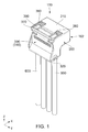
Fig. 1 is a rear, perspective view showing a connector according to an embodiment of the present invention. -
Fig. 2 is an exploded, perspective view showing the connector ofFig. 1 . -
Fig. 3 is an upper view showing the connector ofFig. 1 . -
Fig. 4 is a front, perspective view showing the connector ofFig. 1 . -
Fig. 5 is a cross-sectional view showing the connector ofFig. 3 , taken along line A--A. -
Fig. 6 is an enlarged view showing a part which is enclosed by a quadrangle D of dashed-dotted lines ofFig. 5 . -
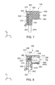
Fig. 7 is a cross-sectional view showing the connector ofFig. 3 , taken along line B--B. -
Fig. 8 is a cross-sectional view showing the connector ofFig. 3 , taken along line C--C. -
Fig. 9 is a rear view showing a first housing which is included in the connector ofFig. 1 . -
Fig. 10 is a cross-sectional view showing the first housing ofFig. 9 , taken along line E--E. -
Fig. 11 is a perspective view showing a second housing which is included in the connector ofFig. 1 . -
Fig. 12 is a perspective view showing the connector ofFig. 1 and a mating connector. The connector and the mating connector are in an unmated state. -
Fig. 13 is another perspective view showing the connector and the mating connector ofFig. 12 . The connector and the mating connector are in a state following the state ofFig. 12 . -
Fig. 14 is still another perspective view showing the connector and the mating connector ofFig. 12 . The connector and the mating connector are in a mated state. -
Fig. 15 is a perspective view showing the connectors and the mating connectors which are arranged in a row. Each of the connectors and the mating connectors is in the unmated state. -
Fig. 16 is another perspective view showing the connectors and the mating connectors ofFig. 15 . Each of the connectors and the mating connectors is in the mated state. -
Fig. 17 is a view showing a connector and a mating connector of Patent Document 1. - While the invention is susceptible to various modifications and alternative forms, specific embodiments thereof are shown by way of example in the drawings and will herein be described in detail. It should be understood, however, that the drawings and detailed description thereto are not intended to limit the invention to the particular form disclosed, but on the contrary, the intention is to cover all modifications, equivalents and alternatives falling within the spirit and scope of the present invention as defined by the appended claims.
- As shown in
Figs. 1 ,4 ,5 ,7 and 8 , aconnector 100 according to an embodiment of the present invention is connected withcables 600. Each of thecables 600 which is connected with theconnector 100 extends in a predetermined direction or a Z-direction. In the present embodiment, the predetermined direction is an up-down direction. As shown inFigs. 12 to 14 , theconnector 100 is mateable with amating connector 500 along a mating direction, or an X-direction. As understood from the above explanation, in the present embodiment, the mating direction of theconnector 100 and themating connector 500 is perpendicular to or intersects with the predetermined direction in which each of thecables 600 extends as shown inFig. 1 . In addition, the mating direction of the present embodiment is referred to as a front-rear direction, too. - As shown in
Fig. 12 , themating connector 500 has a matingfitting portion 505 which is mated with theconnector 100. The matingfitting portion 505 is provided with twomating lock portions 510. Each of themating lock portions 510 of the present embodiment is a protrusion which protrudes upward, or in a positive Z-direction. - As shown in
Figs. 2 ,5 and8 , theconnector 100 comprises afirst housing 200, asecond housing 300 and fourcontacts 400. Thefirst housing 200 is made of insulator. Thesecond housing 300 is made of insulator. Each of thecontacts 400 is made of conductor. - As shown in
Fig. 2 , each of thecontacts 400 has acontact portion 410, ashoulder portion 420 and acable holding portion 430. Thecontact portion 410 has a shape parallel to a horizontal plane, namely, a flat plate-like shape. The horizontal plane is an XY-plane. As shown inFigs. 5 and8 , thecable holding portions 430 hold ends 610 of thecables 600, respectively, so that each of thecables 600 extends in the predetermined direction. As shown inFig. 2 , theshoulder portion 420 couples thecontact portion 410 with thecable holding portion 430. As understood from the above explanation, theconnector 100 of the present embodiment is a so-called angled connector. However, the present invention is not limited thereto. Theconnector 100 may be a so-called straight connector. - With reference to
Figs. 2 and4 , thefirst housing 200 has afitting portion 210 and anaccommodation portion 230. - As shown in
Figs. 4 ,5 and8 , thefitting portion 210 is opened at afront end 102, or a positive X-side end, of theconnector 100. In addition, as shown inFig. 4 ,partition walls 220 are provided inside thefitting portion 210 and divide thefitting portion 210 into four spaces. As described later, the four spaces correspond to the fourcontacts 400, respectively. - As shown in
Figs. 2 and9 , anupper portion 212 of thefitting portion 210 is formed with twoopenings 214. Theopenings 214 are provided so as to correspond to themating lock portions 510, respectively, of themating connector 500 ofFig. 12 . - As shown in
Figs. 2 ,9 and 10 , theaccommodation portion 230 is opened rearward, or in a negative X-direction. As shown inFigs. 2 and9 ,partition walls 232 are provided inside theaccommodation portion 230 and divide theaccommodation portion 230 into four spaces. As described later, the four spaces correspond to the fourcontacts 400, respectively. - As shown in
Fig. 10 , arear wall 216 of thefitting portion 210 is formed withinsertion holes 218 each of which reaches theaccommodation portion 230. The number of the insertion holes 218 is four. The insertion holes 218 correspond to thecontacts 400, respectively. Each of the insertion holes 218 has an elongated, slit-like shape in a plane, or in a YZ-plane, perpendicular to the front-rear direction. As understood fromFigs. 5 ,8 and10 , when each of thecontact portions 410 is inserted into thecorresponding insertion hole 218, each of thecable holding portions 430 is accommodated in theaccommodation portion 230 while each of thecontact portions 410 extends frontward in thefitting portion 210. Thus, each of thecontacts 400 is, at least in part, accommodated in thefirst housing 200. As understood fromFigs. 2 ,9 and 10 , theaccommodation portion 230 is opened rearward. Accordingly, each of thecontacts 400 can be easily accommodated in thefirst housing 200 even after each of thecontacts 400 is connected with thecorresponding cable 600. - As shown in
Figs. 2 and10 , anupper portion 234 of theaccommodation portion 230 is formed with two first upper engagingportions 236 each of which consists of a hole. In addition, first lower engagingportions 252 are provided at lower ends, or negative Z-side ends, of twoside walls 250 of theaccommodation portion 230, respectively. Each of the first lower engagingportions 252 consists of a recess which is recessed upward. Furthermore, as best illustrated inFig. 2 , there is a step difference between theupper portion 234 of theaccommodation portion 230 and theupper portion 212 of thefitting portion 210. By using the step difference, a firstpositional regulating portion 240 is formed between thefitting portion 210 and theaccommodation portion 230. The firstpositional regulating portion 240 of the present embodiment extends in a lateral direction, or a Y-direction. - The aforementioned
first housing 200 is not essentially intended to be deformable. Accordingly, thefirst housing 200 is made of relatively solid material. In contrast, since thesecond housing 300 described below has a part which is resiliently deformable, it is preferable that thesecond housing 300 is made of material which is not harder than other material of which thefirst housing 200 is made. Accordingly, in the present embodiment, thefirst housing 200 is made of material harder than other material of which thesecond housing 300 is made. Thus, solidity of thefirst housing 200 and partial resiliency of thesecond housing 300 can simultaneously be achieved. - As shown in
Figs. 2 and5 , thesecond housing 300 has acover wall 310 which covers theaccommodation portion 230. Thecover wall 310 has a plate-like shape which roughly extends in parallel to a plane, or the YZ-plane, perpendicular to the front-rear direction. As shown inFig. 11 , two second lower engagingportions 312 are provided in the vicinity of a lower end of thecover wall 310. Each of the second lower engagingportions 312 protrudes outward in the lateral direction. The second lower engagingportions 312 correspond to the first lower engaging portions 252 (seeFig. 2 ), respectively. - As shown in
Figs. 2 ,5 ,7 and 8 , thesecond housing 300 is provided with a hookedportion 320. As described later, the hookedportion 320 is a portion which is hooked by a finger when theconnector 100 is released from themating connector 500. The hookedportion 320 of the present embodiment is formed of a planar part which extends rearward and obliquely downward from the lower end of thecover wall 310. Specifically, since the hookedportion 320 intersects with both the mating direction, or the front-rear direction, and the predetermined direction, or the up-down direction, the hookedportion 320 can be easily hooked by a finger. In addition, under a state where each of theends 610 of thecables 600 is held by the correspondingcable holding portion 430, the hookedportion 320 is positioned apart from thecables 600 in the mating direction, or in a perpendicular direction perpendicular to an extending direction in which each of thecables 600 extends. In particular, in the present embodiment, a distance from an end part of the hookedportion 320 to thecables 600 is equal or larger than a diameter of thecable 600. Accordingly, it is easy to insert a finger between thecables 600 and the hookedportion 320 so that the hookedportion 320 is easily hooked by a finger tip. - As shown in
Fig. 11 , a front surface of thecover wall 310 is formed with a plurality of holdingprotrusions 330. As shown inFigs. 5 and8 , the holdingprotrusions 330 press thecontacts 400 against thefirst housing 200 when thesecond housing 300 is attached to thefirst housing 200. - As shown in
Figs. 7 and 8 , thesecond housing 300 further has aspring support portion 340, aspring portion 350 and aseesaw portion 360. - As shown in
Figs. 7, 8 and11 , thespring support portion 340 extends frontward from an upper end of thecover wall 310. As shown inFig. 11 , thespring support portion 340 is formed with two second upper engagingportions 342. Each of the second upper engagingportions 342 according the present embodiment is a protrusion which protrudes downward. When thesecond housing 300 is pivoted on the second lower engagingportions 312 after the second lower engagingportions 312 are engaged in the first lower engaging portions 252 (seeFig. 2 ) of thefirst housing 200, respectively, the second upper engagingportions 342 ride on the upper portion 234 (seeFig. 2 ) of theaccommodation portion 230 and are then received in the first upper engagingportions 236, respectively (seeFig. 8 ). Thus, thesecond housing 300 is attached to thefirst housing 200. At that time, as shown inFig. 8 , the holdingprotrusions 330 press thecontacts 400, which are accommodated in theaccommodation portion 230, against thefirst housing 200 so that each of thecontacts 400 is held by thefirst housing 200 and thesecond housing 300. - As shown in
Figs. 7, 8 and11 , thespring portion 350 is supported by thespring support portion 340. Thespring portion 350 is resiliently deformable and supports theseesaw portion 360. As shown inFig. 3 , theseesaw portion 360 has a widened U-like shape when seen from above. As understood fromFigs. 3 and11 , theseesaw portion 360 has a front portion and a rear portion. The front portion is positioned frontward of thespring portion 350 and the rear portion is positioned rearward of thespring portion 350. The front portion is moved upward when the rear portion is moved downward. Specifically, theseesaw portion 360 is supported by thespring portion 350 so as to be movable in a seesaw manner. In other words, since thespring portion 350, which extends downward from approximately middle of theseesaw portion 360 in the lateral direction, functions as a fulcrum, theseesaw portion 360 is movable in a seesaw manner. - As shown in
Fig. 11 , theseesaw portion 360 is formed with second positional regulatingportions 362, anoperation portion 370 and lockportions 380. Specifically, theoperation portion 370 and thelock portions 380 are supported by thespring portion 350. As shown inFig. 6 , in the front-rear direction, or in the mating direction, each of the second positional regulatingportions 362 is positioned at a position which is positioned slightly rearward of thespring portion 350 and positioned at almost the same position as thespring portion 350. Theoperation portion 370 is formed of a surface of theseesaw portion 360 which is positioned rearward of thespring portion 350. Thelock portions 380 are formed of holes of theseesaw portion 360 each of which is positioned frontward of thespring portion 350. Because of the aforementioned positional relation between theoperation portion 370 and thelock portions 380, each of thelock portions 380 is moved upward when theoperation portion 370 is operated to be pressed downward. As understood fromFigs. 12 to 14 , when each of thelock portions 380 is moved upward, theoperation portion 370 is moved downward. - As shown in
Fig. 11 , the number of the second positional regulatingportions 362 of the present embodiment is two. As shown inFig. 6 , each of the second positional regulatingportions 362 is positioned rearward of the firstpositional regulating portion 240 and faces the firstpositional regulating portion 240 in the front-rear direction. Accordingly, even if a large frontward force, namely, a large force toward thefirst housing 200, is applied to theseesaw portion 360, each of the second positional regulatingportions 362 abuts the firstpositional regulating portion 240 to stop an excessive movement of theseesaw portion 360 so that thespring portion 350 can be prevented from being broken. - As understood from
Figs. 12 and14 , when theconnector 100 is mated with themating connector 500, thelock portions 380 lock themating lock portions 510, respectively. As described above, in the present embodiment, each of themating lock portions 510 is a protrusion, and each of thelock portions 380 is the corresponding hole. As understood fromFigs. 2 and6 , when thesecond housing 300 is attached to thefirst housing 200, thelock portions 380 are positioned in theopenings 214, respectively, which are provided on theupper portion 212 of thefitting portion 210. Accordingly, when the matingfitting portion 505 of the mating connector 500 (seeFig. 12 ) is inserted into thefitting portion 210 of theconnector 100, themating lock portions 510 which are provided on the matingfitting portion 505 of the mating connector 500 (seeFig. 12 ) can lock thelock portions 380 in theopenings 214, respectively. Since each of thelock portions 380 is positioned at a position different from a position of thespring portion 350 in the mating direction as described above, theopenings 214 may be provided so as to correspond only to thelock portions 380, respectively. Accordingly, each of theopenings 214 which are formed on thefirst housing 200 can have a relatively reduced size so that thefirst housing 200 can be secured to have a required strength. - As shown in
Fig. 1 , theoperation portion 370 is positioned apart from the hookedportion 320 in the predetermined direction. The surface, of which theoperation portion 370 is formed, extends rearward and obliquely upward at a rear end of theseesaw portion 360. Specifically, theoperation portion 370 intersects with both the mating direction, or the front-rear direction, and the predetermined direction, or the up-down direction, so that theoperation portion 370 is easily operatable. When theoperation portion 370 is pressed by a finger to be moved toward the hookedportion 320, or moved downward, under a state where the hookedportion 320 is hooked by another finger, each of thelock portions 380 can be moved upward. As understood fromFigs. 12 to 14 , when theoperation portion 370 is operated so as to be moved toward the hookedportion 320, locks of thelock portions 380 against themating lock portions 510 are released so that theconnector 100 can be released from themating connector 500. As understood fromFig. 1 , when theoperation portion 370 is operated so as to be moved toward the hookedportion 320, the fingers of an operator are positioned rearward of theconnector 100 and are apart from thecable 600. Accordingly, for example, in a state where a plurality of theconnectors 100 are mated with a plurality of themating connectors 500 which are attached between twobusbars Figs. 15 and 16 , one of theconnectors 100 can be released from and mated with themating connector 500 corresponding thereto while the remainingconnectors 100 and thecables 600 do not obstruct the release operation and the mate operation. - While the present invention has been described with specific embodiments, the present invention is not limited thereto but may be modified in various manners.
- In the aforementioned embodiment, the mating direction of the
connector 100 and themating connector 500 is perpendicular to the extending direction of thecable 600. However, the present invention is not limited thereto. The mating direction of theconnector 100 and themating connector 500 may be same as the extending direction of thecable 600. Considering operability of theconnector 100 upon the release of theconnector 100 from themating connector 500, it is preferable that the mating direction is perpendicular to the extending direction of thecable 600 similar to the present embodiment. - Although the number of the
contacts 400 of the aforementioned embodiment is four, the present embodiment is not limited thereto. The number of thecontacts 400 may be three or less than three. In addition, the number of thecontacts 400 may be five or more than five. - In the aforementioned embodiment, each of the
mating lock portions 510 is the protrusion and each of thelock portions 380 is the hole. However, the preset invention is not limited thereto. Each of themating lock portions 510 may be a hole while each of thelock portions 380 may be a protrusion. In a case where each of themating lock portions 510 is the protrusion while each of thelock portions 380 is the hole similar to the present embodiment, mating contacts (not shown) which are included in themating connector 500 are not exposed outward so that themating connector 500 has a structure suitable to use as a power supply connector. Accordingly, if themating connector 500 is used as a power supply connector, it is preferable that each of thelock portions 380 is the holes. Alternatively, it is at least preferable that thelock portions 380 are recesses which correspond to the protrusions of themating lock portions 510, respectively. - The present application is based on a Japanese patent application of
JP2014-153435 - While there has been described what is believed to be the preferred embodiment of the invention, those skilled in the art will recognize that other and further modifications may be made thereto without departing from the spirit of the invention, and it is intended to claim all such embodiments that fall within the true scope of the invention.
Claims (10)
- A connector mateable with a mating connector which has a mating lock portion, the connector comprising a first housing, a second housing and a contact, wherein:the first housing accommodates, at least in part, the contact;the contact is provided with a cable holding portion which holds an end of a cable so that the cable extends in a predetermined direction;the second housing is attached to the first housing to hold the contact in cooperation with the first housing;the second housing is provided with a hooked portion, a spring portion, an operation portion and a lock portion;the spring portion is resiliently deformable;the operation portion and the lock portion are supported by the spring portion;the lock portion locks the mating lock portion when the connector and the mating connector are mated with each other;the hooked portion is a portion which is hooked by a finger upon operation of the operation portion;the hooked portion is positioned apart from the operation portion in the predetermined direction; andthe operation portion releases a lock of the lock portion against the mating lock portion when operated to be moved toward the hooked portion.
- The connector as recited in claim 1, wherein:the connector is mated with the mating connector along a mating direction; andthe predetermined direction and the mating direction intersect with each other.
- The connector as recited in claim 1 or 2, wherein:the hooked portion intersects with both a perpendicular direction and the predetermined direction;the perpendicular direction is perpendicular to the predetermined direction; andthe hooked portion is positioned apart from the cable in the perpendicular direction under a state where the end of the cable is held by the cable holding portion.
- The connector as recited in one of claims 1 to 3, wherein:the operation portion intersects with both a perpendicular direction and the predetermined direction; andthe perpendicular direction is perpendicular to the predetermined direction.
- The connector as recited in one of claims 1 to 4, wherein the first housing is made of material harder than other material of which the second housing is made.
- The connector as recited in one of claims 1 to 5, wherein:the second housing is provided with a seesaw portion which is supported by the spring portion; andthe operation portion and the lock portion are provided on the seesaw portion.
- The connector as recited in claim 6, wherein:the first housing is provided with a first positional regulating portion;the seesaw portion is provided with a second positional regulating portion;the second positional regulating portion faces the first positional regulating portion; andwhen a force toward the first housing is applied to the seesaw portion, the second positional regulating portion abuts the first positional regulating portion to regulate a movement of the seesaw portion.
- The connector as recited in one of claims 1 to 7, wherein:the connector is mated with the mating connector along a mating direction; andthe lock portion and the spring portion are positioned at positions different from each other in the mating direction.
- The connector as recited in one of claims 1 to 8, wherein:the mating lock portion is a protrusion; andthe lock portion is a hole which corresponds to the protrusion of the mating lock portion.
- The connector as recited in one of claims 1 to 9, wherein:the second housing is provided with a holding protrusion; andthe holding protrusion presses the contact against the first housing so that the contact is held by the first housing and the second housing.
Applications Claiming Priority (1)
| Application Number | Priority Date | Filing Date | Title |
|---|---|---|---|
| JP2014153435A JP6278860B2 (en) | 2014-07-29 | 2014-07-29 | connector |
Publications (2)
| Publication Number | Publication Date |
|---|---|
| EP2980924A1 true EP2980924A1 (en) | 2016-02-03 |
| EP2980924B1 EP2980924B1 (en) | 2017-07-12 |
Family
ID=53546178
Family Applications (1)
| Application Number | Title | Priority Date | Filing Date |
|---|---|---|---|
| EP15176916.3A Not-in-force EP2980924B1 (en) | 2014-07-29 | 2015-07-15 | Connector |
Country Status (4)
| Country | Link |
|---|---|
| US (1) | US9484670B2 (en) |
| EP (1) | EP2980924B1 (en) |
| JP (1) | JP6278860B2 (en) |
| CN (1) | CN105322374B (en) |
Families Citing this family (6)
| Publication number | Priority date | Publication date | Assignee | Title |
|---|---|---|---|---|
| KR102485025B1 (en) * | 2015-09-14 | 2023-01-05 | 엘지이노텍 주식회사 | Integrated cable and motor assembly including the same |
| JP6593631B2 (en) * | 2015-09-24 | 2019-10-23 | 株式会社オートネットワーク技術研究所 | connector |
| CN108346869B (en) * | 2017-01-24 | 2020-07-03 | 泰科电子(上海)有限公司 | Cable connector |
| JP1622367S (en) * | 2018-06-21 | 2019-01-21 | ||
| JP7536659B2 (en) * | 2021-01-05 | 2024-08-20 | 日本航空電子工業株式会社 | Connector Assembly |
| CN217691769U (en) * | 2022-03-04 | 2022-10-28 | 富士康(昆山)电脑接插件有限公司 | Electric connector and combination thereof |
Citations (6)
| Publication number | Priority date | Publication date | Assignee | Title |
|---|---|---|---|---|
| US5643009A (en) * | 1996-02-26 | 1997-07-01 | The Whitaker Corporation | Electrical connector having a pivot lock |
| WO1998007213A2 (en) * | 1996-08-12 | 1998-02-19 | Thomas & Betts International, Inc. | Orientationless squib connector assembly for automotive air bag assemblies |
| US5895285A (en) * | 1997-04-07 | 1999-04-20 | Yazaki Corporation | Press-contact type connector |
| EP1523070A1 (en) * | 2003-10-09 | 2005-04-13 | J.S.T. Mfg. Co., Ltd. | Electrical connecting device |
| US7354310B1 (en) * | 2007-06-07 | 2008-04-08 | Fci Americas Technology, Inc. | Electrical connector housing cover |
| JP2009004247A (en) | 2007-06-22 | 2009-01-08 | Jst Mfg Co Ltd | connector |
Family Cites Families (22)
| Publication number | Priority date | Publication date | Assignee | Title |
|---|---|---|---|---|
| JP2593897B2 (en) | 1987-11-26 | 1997-03-26 | 株式会社クラレ | New crosslinking method |
| JP2593897Y2 (en) | 1988-10-14 | 1999-04-19 | 古河電気工業株式会社 | Connector unit locking device |
| WO2000004609A1 (en) * | 1998-07-15 | 2000-01-27 | Thomas & Betts International, Inc. | Connector for airbag gas generator |
| JP2000182716A (en) | 1998-12-11 | 2000-06-30 | D D K Ltd | Electrical connector |
| JP2001135412A (en) | 1999-11-02 | 2001-05-18 | Japan Aviation Electronics Industry Ltd | Connector with locking mechanism |
| JP2001357900A (en) | 2000-06-14 | 2001-12-26 | Japan Automat Mach Co Ltd | Connector and connector manufacturing method |
| US6398590B2 (en) * | 2000-07-11 | 2002-06-04 | Tyco Electronics Corporation | Nonpolarized electrical connector assembly especially for use as automotive squib connector |
| JP2003249308A (en) * | 2002-02-25 | 2003-09-05 | Tyco Electronics Amp Kk | Electrical connector assembly |
| US6799999B2 (en) * | 2003-02-07 | 2004-10-05 | Fci Americas Technology, Inc. | Filtered electrical connector |
| US6964579B2 (en) * | 2003-06-06 | 2005-11-15 | Fci Americas Technology, Inc. | Position assured connector |
| US7004778B2 (en) * | 2003-07-07 | 2006-02-28 | Kent Barker | Electrical connection apparatus and method for an airbag inflator |
| US6997750B2 (en) * | 2003-07-23 | 2006-02-14 | Fci Americas Technology, Inc. | Electrical connector contact |
| US7264496B2 (en) * | 2004-02-25 | 2007-09-04 | Hon Hai Precision Ind. Co., Ltd. | Cable assembly having locking member on opposite sides thereof |
| JP2005243550A (en) * | 2004-02-27 | 2005-09-08 | Sumitomo Wiring Syst Ltd | Connector |
| JP4338084B2 (en) | 2004-03-10 | 2009-09-30 | タイコエレクトロニクスアンプ株式会社 | Electrical connector with lock arm |
| CN2770136Y (en) * | 2004-12-25 | 2006-04-05 | 富士康(昆山)电脑接插件有限公司 | Cable connector assembly |
| JP2012022900A (en) * | 2010-07-15 | 2012-02-02 | Sumitomo Wiring Syst Ltd | Connector |
| JP5602617B2 (en) * | 2010-12-28 | 2014-10-08 | タイコエレクトロニクスジャパン合同会社 | Connector member |
| US9196999B2 (en) * | 2010-12-28 | 2015-11-24 | Rit Technologies Ltd. | Two-part modular connector and smart managed interconnect link using the two-part modular connector |
| JP5654505B2 (en) | 2012-01-25 | 2015-01-14 | ケル株式会社 | Connector device |
| CN103490214A (en) * | 2012-06-13 | 2014-01-01 | 富士康(昆山)电脑接插件有限公司 | Cable connector assembly |
| JP6042168B2 (en) * | 2012-10-17 | 2016-12-14 | 日本圧着端子製造株式会社 | Electrical connector and squib connection device |
-
2014
- 2014-07-29 JP JP2014153435A patent/JP6278860B2/en active Active
-
2015
- 2015-06-18 US US14/743,462 patent/US9484670B2/en not_active Expired - Fee Related
- 2015-06-18 CN CN201510340596.4A patent/CN105322374B/en active Active
- 2015-07-15 EP EP15176916.3A patent/EP2980924B1/en not_active Not-in-force
Patent Citations (6)
| Publication number | Priority date | Publication date | Assignee | Title |
|---|---|---|---|---|
| US5643009A (en) * | 1996-02-26 | 1997-07-01 | The Whitaker Corporation | Electrical connector having a pivot lock |
| WO1998007213A2 (en) * | 1996-08-12 | 1998-02-19 | Thomas & Betts International, Inc. | Orientationless squib connector assembly for automotive air bag assemblies |
| US5895285A (en) * | 1997-04-07 | 1999-04-20 | Yazaki Corporation | Press-contact type connector |
| EP1523070A1 (en) * | 2003-10-09 | 2005-04-13 | J.S.T. Mfg. Co., Ltd. | Electrical connecting device |
| US7354310B1 (en) * | 2007-06-07 | 2008-04-08 | Fci Americas Technology, Inc. | Electrical connector housing cover |
| JP2009004247A (en) | 2007-06-22 | 2009-01-08 | Jst Mfg Co Ltd | connector |
Also Published As
| Publication number | Publication date |
|---|---|
| CN105322374B (en) | 2017-10-27 |
| US9484670B2 (en) | 2016-11-01 |
| EP2980924B1 (en) | 2017-07-12 |
| CN105322374A (en) | 2016-02-10 |
| JP2016031824A (en) | 2016-03-07 |
| JP6278860B2 (en) | 2018-02-14 |
| US20160036163A1 (en) | 2016-02-04 |
Similar Documents
| Publication | Publication Date | Title |
|---|---|---|
| US9484670B2 (en) | Connector assembly with enabling contact and housing structure | |
| CN103378449B (en) | Connector | |
| US9590355B2 (en) | Connector and connector assembly | |
| US10276980B2 (en) | Connector with a CPA receiving space and connector assembly comprising such a connector | |
| US9246260B2 (en) | Electrical connector | |
| EP3460921B1 (en) | Connector | |
| US9979127B2 (en) | Electrical connector and electrical connector assembly | |
| JP2018139209A (en) | Electrical connector with terminal position assurance device | |
| CN111418117A (en) | Electrical connector with terminal position assurance member | |
| JP2018120686A (en) | connector | |
| EP3190667A1 (en) | Connector and connector assembly | |
| CN101325299B (en) | Electric connector | |
| JP2018147788A (en) | connector | |
| US20150255922A1 (en) | Connector | |
| US20160359273A1 (en) | Connector | |
| JP2019067744A (en) | connector | |
| JP2016157643A (en) | Connector assembly | |
| KR101868302B1 (en) | Electrical connector assembly comprising an array of elongated electrical contacts | |
| US9780486B2 (en) | Connector | |
| JP2015056244A (en) | Connector device | |
| JP6931975B2 (en) | connector | |
| TWI802639B (en) | Connector device with terminal pressing structure | |
| JP4575791B2 (en) | Plug retaining tool and plug retaining mechanism | |
| CN105098434A (en) | Electrical connector | |
| CN104979719A (en) | Usb receptacle |
Legal Events
| Date | Code | Title | Description |
|---|---|---|---|
| PUAI | Public reference made under article 153(3) epc to a published international application that has entered the european phase |
Free format text: ORIGINAL CODE: 0009012 |
|
| AK | Designated contracting states |
Kind code of ref document: A1 Designated state(s): AL AT BE BG CH CY CZ DE DK EE ES FI FR GB GR HR HU IE IS IT LI LT LU LV MC MK MT NL NO PL PT RO RS SE SI SK SM TR |
|
| AX | Request for extension of the european patent |
Extension state: BA ME |
|
| 17P | Request for examination filed |
Effective date: 20160415 |
|
| RBV | Designated contracting states (corrected) |
Designated state(s): AL AT BE BG CH CY CZ DE DK EE ES FI FR GB GR HR HU IE IS IT LI LT LU LV MC MK MT NL NO PL PT RO RS SE SI SK SM TR |
|
| 17Q | First examination report despatched |
Effective date: 20160721 |
|
| GRAP | Despatch of communication of intention to grant a patent |
Free format text: ORIGINAL CODE: EPIDOSNIGR1 |
|
| RIC1 | Information provided on ipc code assigned before grant |
Ipc: H01R 13/436 20060101AFI20170208BHEP Ipc: H01R 13/627 20060101ALN20170208BHEP Ipc: H01R 13/506 20060101ALN20170208BHEP |
|
| RIC1 | Information provided on ipc code assigned before grant |
Ipc: H01R 13/627 20060101ALN20170216BHEP Ipc: H01R 13/506 20060101ALN20170216BHEP Ipc: H01R 13/436 20060101AFI20170216BHEP |
|
| INTG | Intention to grant announced |
Effective date: 20170301 |
|
| GRAS | Grant fee paid |
Free format text: ORIGINAL CODE: EPIDOSNIGR3 |
|
| GRAA | (expected) grant |
Free format text: ORIGINAL CODE: 0009210 |
|
| AK | Designated contracting states |
Kind code of ref document: B1 Designated state(s): AL AT BE BG CH CY CZ DE DK EE ES FI FR GB GR HR HU IE IS IT LI LT LU LV MC MK MT NL NO PL PT RO RS SE SI SK SM TR |
|
| REG | Reference to a national code |
Ref country code: GB Ref legal event code: FG4D |
|
| REG | Reference to a national code |
Ref country code: CH Ref legal event code: EP |
|
| REG | Reference to a national code |
Ref country code: AT Ref legal event code: REF Ref document number: 909154 Country of ref document: AT Kind code of ref document: T Effective date: 20170715 |
|
| REG | Reference to a national code |
Ref country code: IE Ref legal event code: FG4D |
|
| REG | Reference to a national code |
Ref country code: DE Ref legal event code: R096 Ref document number: 602015003511 Country of ref document: DE |
|
| REG | Reference to a national code |
Ref country code: NL Ref legal event code: MP Effective date: 20170712 |
|
| REG | Reference to a national code |
Ref country code: LT Ref legal event code: MG4D |
|
| REG | Reference to a national code |
Ref country code: AT Ref legal event code: MK05 Ref document number: 909154 Country of ref document: AT Kind code of ref document: T Effective date: 20170712 |
|
| PG25 | Lapsed in a contracting state [announced via postgrant information from national office to epo] |
Ref country code: LT Free format text: LAPSE BECAUSE OF FAILURE TO SUBMIT A TRANSLATION OF THE DESCRIPTION OR TO PAY THE FEE WITHIN THE PRESCRIBED TIME-LIMIT Effective date: 20170712 Ref country code: HR Free format text: LAPSE BECAUSE OF FAILURE TO SUBMIT A TRANSLATION OF THE DESCRIPTION OR TO PAY THE FEE WITHIN THE PRESCRIBED TIME-LIMIT Effective date: 20170712 Ref country code: SE Free format text: LAPSE BECAUSE OF FAILURE TO SUBMIT A TRANSLATION OF THE DESCRIPTION OR TO PAY THE FEE WITHIN THE PRESCRIBED TIME-LIMIT Effective date: 20170712 Ref country code: AT Free format text: LAPSE BECAUSE OF FAILURE TO SUBMIT A TRANSLATION OF THE DESCRIPTION OR TO PAY THE FEE WITHIN THE PRESCRIBED TIME-LIMIT Effective date: 20170712 Ref country code: NO Free format text: LAPSE BECAUSE OF FAILURE TO SUBMIT A TRANSLATION OF THE DESCRIPTION OR TO PAY THE FEE WITHIN THE PRESCRIBED TIME-LIMIT Effective date: 20171012 Ref country code: FI Free format text: LAPSE BECAUSE OF FAILURE TO SUBMIT A TRANSLATION OF THE DESCRIPTION OR TO PAY THE FEE WITHIN THE PRESCRIBED TIME-LIMIT Effective date: 20170712 Ref country code: NL Free format text: LAPSE BECAUSE OF FAILURE TO SUBMIT A TRANSLATION OF THE DESCRIPTION OR TO PAY THE FEE WITHIN THE PRESCRIBED TIME-LIMIT Effective date: 20170712 |
|
| PG25 | Lapsed in a contracting state [announced via postgrant information from national office to epo] |
Ref country code: BG Free format text: LAPSE BECAUSE OF FAILURE TO SUBMIT A TRANSLATION OF THE DESCRIPTION OR TO PAY THE FEE WITHIN THE PRESCRIBED TIME-LIMIT Effective date: 20171012 Ref country code: LV Free format text: LAPSE BECAUSE OF FAILURE TO SUBMIT A TRANSLATION OF THE DESCRIPTION OR TO PAY THE FEE WITHIN THE PRESCRIBED TIME-LIMIT Effective date: 20170712 Ref country code: IS Free format text: LAPSE BECAUSE OF FAILURE TO SUBMIT A TRANSLATION OF THE DESCRIPTION OR TO PAY THE FEE WITHIN THE PRESCRIBED TIME-LIMIT Effective date: 20171112 Ref country code: ES Free format text: LAPSE BECAUSE OF FAILURE TO SUBMIT A TRANSLATION OF THE DESCRIPTION OR TO PAY THE FEE WITHIN THE PRESCRIBED TIME-LIMIT Effective date: 20170712 Ref country code: RS Free format text: LAPSE BECAUSE OF FAILURE TO SUBMIT A TRANSLATION OF THE DESCRIPTION OR TO PAY THE FEE WITHIN THE PRESCRIBED TIME-LIMIT Effective date: 20170712 Ref country code: PL Free format text: LAPSE BECAUSE OF FAILURE TO SUBMIT A TRANSLATION OF THE DESCRIPTION OR TO PAY THE FEE WITHIN THE PRESCRIBED TIME-LIMIT Effective date: 20170712 Ref country code: GR Free format text: LAPSE BECAUSE OF FAILURE TO SUBMIT A TRANSLATION OF THE DESCRIPTION OR TO PAY THE FEE WITHIN THE PRESCRIBED TIME-LIMIT Effective date: 20171013 |
|
| REG | Reference to a national code |
Ref country code: DE Ref legal event code: R097 Ref document number: 602015003511 Country of ref document: DE |
|
| REG | Reference to a national code |
Ref country code: IE Ref legal event code: MM4A |
|
| PG25 | Lapsed in a contracting state [announced via postgrant information from national office to epo] |
Ref country code: DK Free format text: LAPSE BECAUSE OF FAILURE TO SUBMIT A TRANSLATION OF THE DESCRIPTION OR TO PAY THE FEE WITHIN THE PRESCRIBED TIME-LIMIT Effective date: 20170712 Ref country code: CZ Free format text: LAPSE BECAUSE OF FAILURE TO SUBMIT A TRANSLATION OF THE DESCRIPTION OR TO PAY THE FEE WITHIN THE PRESCRIBED TIME-LIMIT Effective date: 20170712 Ref country code: MC Free format text: LAPSE BECAUSE OF FAILURE TO SUBMIT A TRANSLATION OF THE DESCRIPTION OR TO PAY THE FEE WITHIN THE PRESCRIBED TIME-LIMIT Effective date: 20170712 Ref country code: RO Free format text: LAPSE BECAUSE OF FAILURE TO SUBMIT A TRANSLATION OF THE DESCRIPTION OR TO PAY THE FEE WITHIN THE PRESCRIBED TIME-LIMIT Effective date: 20170712 Ref country code: IE Free format text: LAPSE BECAUSE OF NON-PAYMENT OF DUE FEES Effective date: 20170715 |
|
| REG | Reference to a national code |
Ref country code: BE Ref legal event code: MM Effective date: 20170731 |
|
| PLBE | No opposition filed within time limit |
Free format text: ORIGINAL CODE: 0009261 |
|
| STAA | Information on the status of an ep patent application or granted ep patent |
Free format text: STATUS: NO OPPOSITION FILED WITHIN TIME LIMIT |
|
| PG25 | Lapsed in a contracting state [announced via postgrant information from national office to epo] |
Ref country code: SK Free format text: LAPSE BECAUSE OF FAILURE TO SUBMIT A TRANSLATION OF THE DESCRIPTION OR TO PAY THE FEE WITHIN THE PRESCRIBED TIME-LIMIT Effective date: 20170712 Ref country code: EE Free format text: LAPSE BECAUSE OF FAILURE TO SUBMIT A TRANSLATION OF THE DESCRIPTION OR TO PAY THE FEE WITHIN THE PRESCRIBED TIME-LIMIT Effective date: 20170712 Ref country code: IT Free format text: LAPSE BECAUSE OF FAILURE TO SUBMIT A TRANSLATION OF THE DESCRIPTION OR TO PAY THE FEE WITHIN THE PRESCRIBED TIME-LIMIT Effective date: 20170712 Ref country code: SM Free format text: LAPSE BECAUSE OF FAILURE TO SUBMIT A TRANSLATION OF THE DESCRIPTION OR TO PAY THE FEE WITHIN THE PRESCRIBED TIME-LIMIT Effective date: 20170712 |
|
| 26N | No opposition filed |
Effective date: 20180413 |
|
| PG25 | Lapsed in a contracting state [announced via postgrant information from national office to epo] |
Ref country code: LU Free format text: LAPSE BECAUSE OF NON-PAYMENT OF DUE FEES Effective date: 20170715 |
|
| REG | Reference to a national code |
Ref country code: FR Ref legal event code: ST Effective date: 20180529 |
|
| PG25 | Lapsed in a contracting state [announced via postgrant information from national office to epo] |
Ref country code: FR Free format text: LAPSE BECAUSE OF NON-PAYMENT OF DUE FEES Effective date: 20170912 Ref country code: BE Free format text: LAPSE BECAUSE OF NON-PAYMENT OF DUE FEES Effective date: 20170731 Ref country code: SI Free format text: LAPSE BECAUSE OF FAILURE TO SUBMIT A TRANSLATION OF THE DESCRIPTION OR TO PAY THE FEE WITHIN THE PRESCRIBED TIME-LIMIT Effective date: 20170712 |
|
| PG25 | Lapsed in a contracting state [announced via postgrant information from national office to epo] |
Ref country code: MT Free format text: LAPSE BECAUSE OF NON-PAYMENT OF DUE FEES Effective date: 20170715 |
|
| REG | Reference to a national code |
Ref country code: CH Ref legal event code: PL |
|
| PG25 | Lapsed in a contracting state [announced via postgrant information from national office to epo] |
Ref country code: LI Free format text: LAPSE BECAUSE OF NON-PAYMENT OF DUE FEES Effective date: 20180731 Ref country code: CH Free format text: LAPSE BECAUSE OF NON-PAYMENT OF DUE FEES Effective date: 20180731 |
|
| PG25 | Lapsed in a contracting state [announced via postgrant information from national office to epo] |
Ref country code: HU Free format text: LAPSE BECAUSE OF FAILURE TO SUBMIT A TRANSLATION OF THE DESCRIPTION OR TO PAY THE FEE WITHIN THE PRESCRIBED TIME-LIMIT; INVALID AB INITIO Effective date: 20150715 |
|
| PG25 | Lapsed in a contracting state [announced via postgrant information from national office to epo] |
Ref country code: CY Free format text: LAPSE BECAUSE OF FAILURE TO SUBMIT A TRANSLATION OF THE DESCRIPTION OR TO PAY THE FEE WITHIN THE PRESCRIBED TIME-LIMIT Effective date: 20170712 |
|
| PG25 | Lapsed in a contracting state [announced via postgrant information from national office to epo] |
Ref country code: MK Free format text: LAPSE BECAUSE OF FAILURE TO SUBMIT A TRANSLATION OF THE DESCRIPTION OR TO PAY THE FEE WITHIN THE PRESCRIBED TIME-LIMIT Effective date: 20170712 |
|
| GBPC | Gb: european patent ceased through non-payment of renewal fee |
Effective date: 20190715 |
|
| PG25 | Lapsed in a contracting state [announced via postgrant information from national office to epo] |
Ref country code: TR Free format text: LAPSE BECAUSE OF FAILURE TO SUBMIT A TRANSLATION OF THE DESCRIPTION OR TO PAY THE FEE WITHIN THE PRESCRIBED TIME-LIMIT Effective date: 20170712 |
|
| PG25 | Lapsed in a contracting state [announced via postgrant information from national office to epo] |
Ref country code: GB Free format text: LAPSE BECAUSE OF NON-PAYMENT OF DUE FEES Effective date: 20190715 |
|
| PG25 | Lapsed in a contracting state [announced via postgrant information from national office to epo] |
Ref country code: PT Free format text: LAPSE BECAUSE OF FAILURE TO SUBMIT A TRANSLATION OF THE DESCRIPTION OR TO PAY THE FEE WITHIN THE PRESCRIBED TIME-LIMIT Effective date: 20170712 |
|
| PG25 | Lapsed in a contracting state [announced via postgrant information from national office to epo] |
Ref country code: AL Free format text: LAPSE BECAUSE OF FAILURE TO SUBMIT A TRANSLATION OF THE DESCRIPTION OR TO PAY THE FEE WITHIN THE PRESCRIBED TIME-LIMIT Effective date: 20170712 |
|
| PGFP | Annual fee paid to national office [announced via postgrant information from national office to epo] |
Ref country code: DE Payment date: 20230531 Year of fee payment: 9 |
|
| REG | Reference to a national code |
Ref country code: DE Ref legal event code: R119 Ref document number: 602015003511 Country of ref document: DE |
|
| PG25 | Lapsed in a contracting state [announced via postgrant information from national office to epo] |
Ref country code: DE Free format text: LAPSE BECAUSE OF NON-PAYMENT OF DUE FEES Effective date: 20250201 |